JP4636372B2 - Liquid ejector - Google Patents
Liquid ejector Download PDFInfo
- Publication number
- JP4636372B2 JP4636372B2 JP2005103561A JP2005103561A JP4636372B2 JP 4636372 B2 JP4636372 B2 JP 4636372B2 JP 2005103561 A JP2005103561 A JP 2005103561A JP 2005103561 A JP2005103561 A JP 2005103561A JP 4636372 B2 JP4636372 B2 JP 4636372B2
- Authority
- JP
- Japan
- Prior art keywords
- data
- pulse waveform
- drive signal
- pulse
- gradation data
- Prior art date
- Legal status (The legal status is an assumption and is not a legal conclusion. Google has not performed a legal analysis and makes no representation as to the accuracy of the status listed.)
- Expired - Fee Related
Links
- 239000007788 liquid Substances 0.000 title claims description 57
- 238000007599 discharging Methods 0.000 claims description 10
- 230000000737 periodic effect Effects 0.000 claims description 4
- 239000000976 ink Substances 0.000 description 128
- 101000746134 Homo sapiens DNA endonuclease RBBP8 Proteins 0.000 description 12
- 101000969031 Homo sapiens Nuclear protein 1 Proteins 0.000 description 12
- 102100021133 Nuclear protein 1 Human genes 0.000 description 12
- 230000007274 generation of a signal involved in cell-cell signaling Effects 0.000 description 12
- 230000006870 function Effects 0.000 description 10
- 230000005499 meniscus Effects 0.000 description 8
- 238000000034 method Methods 0.000 description 5
- 238000010586 diagram Methods 0.000 description 3
- 230000010355 oscillation Effects 0.000 description 3
- 238000012545 processing Methods 0.000 description 3
- 101100189362 Arabidopsis thaliana PAPS1 gene Proteins 0.000 description 2
- 101100189366 Arabidopsis thaliana PAPS2 gene Proteins 0.000 description 2
- 101100189369 Arabidopsis thaliana PAPS3 gene Proteins 0.000 description 2
- 238000005520 cutting process Methods 0.000 description 2
- 238000005530 etching Methods 0.000 description 2
- 229910001220 stainless steel Inorganic materials 0.000 description 2
- 239000010935 stainless steel Substances 0.000 description 2
- 238000003860 storage Methods 0.000 description 2
- 206010010071 Coma Diseases 0.000 description 1
- 101000785279 Dictyostelium discoideum Calcium-transporting ATPase PAT1 Proteins 0.000 description 1
- 101001129314 Dictyostelium discoideum Probable plasma membrane ATPase Proteins 0.000 description 1
- 101000779309 Homo sapiens Amyloid protein-binding protein 2 Proteins 0.000 description 1
- 101000713296 Homo sapiens Proton-coupled amino acid transporter 1 Proteins 0.000 description 1
- 101000713293 Homo sapiens Proton-coupled amino acid transporter 2 Proteins 0.000 description 1
- 101000713290 Homo sapiens Proton-coupled amino acid transporter 3 Proteins 0.000 description 1
- 102100036920 Proton-coupled amino acid transporter 1 Human genes 0.000 description 1
- 102100036919 Proton-coupled amino acid transporter 2 Human genes 0.000 description 1
- 102100036918 Proton-coupled amino acid transporter 3 Human genes 0.000 description 1
- XUIMIQQOPSSXEZ-UHFFFAOYSA-N Silicon Chemical compound [Si] XUIMIQQOPSSXEZ-UHFFFAOYSA-N 0.000 description 1
- 241000610628 Trichoptilium incisum Species 0.000 description 1
- 230000005540 biological transmission Effects 0.000 description 1
- 230000015572 biosynthetic process Effects 0.000 description 1
- 239000003086 colorant Substances 0.000 description 1
- 230000008602 contraction Effects 0.000 description 1
- 238000005034 decoration Methods 0.000 description 1
- 230000007423 decrease Effects 0.000 description 1
- 230000003247 decreasing effect Effects 0.000 description 1
- 238000011161 development Methods 0.000 description 1
- 239000007772 electrode material Substances 0.000 description 1
- 238000005516 engineering process Methods 0.000 description 1
- 239000003292 glue Substances 0.000 description 1
- 238000010438 heat treatment Methods 0.000 description 1
- 238000010030 laminating Methods 0.000 description 1
- 239000004973 liquid crystal related substance Substances 0.000 description 1
- 238000004519 manufacturing process Methods 0.000 description 1
- 239000000463 material Substances 0.000 description 1
- -1 nail polish Substances 0.000 description 1
- 238000005192 partition Methods 0.000 description 1
- 229920006254 polymer film Polymers 0.000 description 1
- 238000011160 research Methods 0.000 description 1
- 229910052710 silicon Inorganic materials 0.000 description 1
- 239000010703 silicon Substances 0.000 description 1
- 238000013519 translation Methods 0.000 description 1
Images


Classifications
-
- B—PERFORMING OPERATIONS; TRANSPORTING
- B41—PRINTING; LINING MACHINES; TYPEWRITERS; STAMPS
- B41J—TYPEWRITERS; SELECTIVE PRINTING MECHANISMS, i.e. MECHANISMS PRINTING OTHERWISE THAN FROM A FORME; CORRECTION OF TYPOGRAPHICAL ERRORS
- B41J2/00—Typewriters or selective printing mechanisms characterised by the printing or marking process for which they are designed
- B41J2/005—Typewriters or selective printing mechanisms characterised by the printing or marking process for which they are designed characterised by bringing liquid or particles selectively into contact with a printing material
- B41J2/01—Ink jet
- B41J2/21—Ink jet for multi-colour printing
- B41J2/2121—Ink jet for multi-colour printing characterised by dot size, e.g. combinations of printed dots of different diameter
- B41J2/2128—Ink jet for multi-colour printing characterised by dot size, e.g. combinations of printed dots of different diameter by means of energy modulation
-
- B—PERFORMING OPERATIONS; TRANSPORTING
- B41—PRINTING; LINING MACHINES; TYPEWRITERS; STAMPS
- B41J—TYPEWRITERS; SELECTIVE PRINTING MECHANISMS, i.e. MECHANISMS PRINTING OTHERWISE THAN FROM A FORME; CORRECTION OF TYPOGRAPHICAL ERRORS
- B41J2/00—Typewriters or selective printing mechanisms characterised by the printing or marking process for which they are designed
- B41J2/005—Typewriters or selective printing mechanisms characterised by the printing or marking process for which they are designed characterised by bringing liquid or particles selectively into contact with a printing material
- B41J2/01—Ink jet
- B41J2/015—Ink jet characterised by the jet generation process
- B41J2/04—Ink jet characterised by the jet generation process generating single droplets or particles on demand
- B41J2/045—Ink jet characterised by the jet generation process generating single droplets or particles on demand by pressure, e.g. electromechanical transducers
- B41J2/04501—Control methods or devices therefor, e.g. driver circuits, control circuits
- B41J2/04581—Control methods or devices therefor, e.g. driver circuits, control circuits controlling heads based on piezoelectric elements
-
- B—PERFORMING OPERATIONS; TRANSPORTING
- B41—PRINTING; LINING MACHINES; TYPEWRITERS; STAMPS
- B41J—TYPEWRITERS; SELECTIVE PRINTING MECHANISMS, i.e. MECHANISMS PRINTING OTHERWISE THAN FROM A FORME; CORRECTION OF TYPOGRAPHICAL ERRORS
- B41J2/00—Typewriters or selective printing mechanisms characterised by the printing or marking process for which they are designed
- B41J2/005—Typewriters or selective printing mechanisms characterised by the printing or marking process for which they are designed characterised by bringing liquid or particles selectively into contact with a printing material
- B41J2/01—Ink jet
- B41J2/015—Ink jet characterised by the jet generation process
- B41J2/04—Ink jet characterised by the jet generation process generating single droplets or particles on demand
- B41J2/045—Ink jet characterised by the jet generation process generating single droplets or particles on demand by pressure, e.g. electromechanical transducers
- B41J2/04501—Control methods or devices therefor, e.g. driver circuits, control circuits
- B41J2/04588—Control methods or devices therefor, e.g. driver circuits, control circuits using a specific waveform
-
- B—PERFORMING OPERATIONS; TRANSPORTING
- B41—PRINTING; LINING MACHINES; TYPEWRITERS; STAMPS
- B41J—TYPEWRITERS; SELECTIVE PRINTING MECHANISMS, i.e. MECHANISMS PRINTING OTHERWISE THAN FROM A FORME; CORRECTION OF TYPOGRAPHICAL ERRORS
- B41J2/00—Typewriters or selective printing mechanisms characterised by the printing or marking process for which they are designed
- B41J2/005—Typewriters or selective printing mechanisms characterised by the printing or marking process for which they are designed characterised by bringing liquid or particles selectively into contact with a printing material
- B41J2/01—Ink jet
- B41J2/015—Ink jet characterised by the jet generation process
- B41J2/04—Ink jet characterised by the jet generation process generating single droplets or particles on demand
- B41J2/045—Ink jet characterised by the jet generation process generating single droplets or particles on demand by pressure, e.g. electromechanical transducers
- B41J2/04501—Control methods or devices therefor, e.g. driver circuits, control circuits
- B41J2/04593—Dot-size modulation by changing the size of the drop
-
- B—PERFORMING OPERATIONS; TRANSPORTING
- B41—PRINTING; LINING MACHINES; TYPEWRITERS; STAMPS
- B41J—TYPEWRITERS; SELECTIVE PRINTING MECHANISMS, i.e. MECHANISMS PRINTING OTHERWISE THAN FROM A FORME; CORRECTION OF TYPOGRAPHICAL ERRORS
- B41J2/00—Typewriters or selective printing mechanisms characterised by the printing or marking process for which they are designed
- B41J2/005—Typewriters or selective printing mechanisms characterised by the printing or marking process for which they are designed characterised by bringing liquid or particles selectively into contact with a printing material
- B41J2/01—Ink jet
- B41J2/015—Ink jet characterised by the jet generation process
- B41J2/04—Ink jet characterised by the jet generation process generating single droplets or particles on demand
- B41J2/045—Ink jet characterised by the jet generation process generating single droplets or particles on demand by pressure, e.g. electromechanical transducers
- B41J2/04501—Control methods or devices therefor, e.g. driver circuits, control circuits
- B41J2/04595—Dot-size modulation by changing the number of drops per dot
-
- B—PERFORMING OPERATIONS; TRANSPORTING
- B41—PRINTING; LINING MACHINES; TYPEWRITERS; STAMPS
- B41J—TYPEWRITERS; SELECTIVE PRINTING MECHANISMS, i.e. MECHANISMS PRINTING OTHERWISE THAN FROM A FORME; CORRECTION OF TYPOGRAPHICAL ERRORS
- B41J2/00—Typewriters or selective printing mechanisms characterised by the printing or marking process for which they are designed
- B41J2/005—Typewriters or selective printing mechanisms characterised by the printing or marking process for which they are designed characterised by bringing liquid or particles selectively into contact with a printing material
- B41J2/01—Ink jet
- B41J2/015—Ink jet characterised by the jet generation process
- B41J2/04—Ink jet characterised by the jet generation process generating single droplets or particles on demand
- B41J2/045—Ink jet characterised by the jet generation process generating single droplets or particles on demand by pressure, e.g. electromechanical transducers
- B41J2/04501—Control methods or devices therefor, e.g. driver circuits, control circuits
- B41J2/04596—Non-ejecting pulses
Description
本発明は、ノズル開口から液体滴を吐出させる液体噴射装置に関する。 The present invention relates to a liquid ejecting apparatus that ejects liquid droplets from nozzle openings.
インクジェット式プリンタやインクジェット式プロッタ等のインクジェット式記録装置(液体噴射装置の一種)は、記録ヘッド(ヘッド部材)を主走査方向に沿って移動させると共に記録紙(印刷記録用媒体の一種)を副走査方向に沿って移動させ、この移動に連動して記録ヘッドのノズル開口からインク滴を吐出させることにより、記録紙上に画像(文字を含む)を記録する。このインク滴の吐出は、例えば、ノズル開口に連通した圧力発生室を膨張・収縮させることで行われる。 An ink jet recording apparatus (a type of liquid ejecting apparatus) such as an ink jet printer or an ink jet plotter moves a recording head (head member) along the main scanning direction and also transfers a recording paper (a type of printing recording medium). An image (including characters) is recorded on the recording paper by moving along the scanning direction and ejecting ink droplets from the nozzle openings of the recording head in conjunction with the movement. The ink droplets are ejected, for example, by expanding and contracting a pressure generating chamber that communicates with the nozzle opening.
圧力発生室の膨張・収縮は、例えば、圧電振動子の変形を利用して行われる。このような記録ヘッドでは、供給される駆動パルスに応じて圧電振動子が変形し、これにより圧力室の容積が変化し、この容積変化によって圧力室内のインクに圧力変動が生じて、ノズル開口からインク滴が吐出する。 The expansion / contraction of the pressure generating chamber is performed using, for example, deformation of the piezoelectric vibrator. In such a recording head, the piezoelectric vibrator is deformed in accordance with the supplied driving pulse, thereby changing the volume of the pressure chamber, and this volume change causes a pressure fluctuation in the ink in the pressure chamber, and the nozzle opening. Ink droplets are ejected.
このような記録装置では、複数の駆動パルスを一連に接続してなる駆動信号が生成される。一方、階調情報を含む印字データが記録ヘッドに送信される。そして、当該送信された印字データに基づいて、必要な駆動パルスのみが前記駆動信号から選択されて圧電振動子に供給される。これにより、ノズル開口から吐出させるインク滴の量を、階調情報に応じて変化させている。 In such a recording apparatus, a drive signal formed by connecting a plurality of drive pulses in series is generated. On the other hand, print data including gradation information is transmitted to the recording head. Then, based on the transmitted print data, only the necessary drive pulse is selected from the drive signal and supplied to the piezoelectric vibrator. Thereby, the amount of ink droplets ejected from the nozzle openings is changed according to the gradation information.
より具体的には、例えば、非記録の印字データ(階調情報00)、小ドットの印字データ(階調情報01)、中ドットの印字データ(階調情報10)、及び、大ドットの印字データ(階調情報11)からなる4階調を設定したプリンタにおいては、それぞれの階調に応じて、インク量の異なるインク滴が吐出される。 More specifically, for example, non-recording print data (gradation information 00), small dot print data (gradation information 01), medium dot print data (gradation information 10), and large dot printing In a printer in which four gradations composed of data (gradation information 11) are set, ink droplets having different ink amounts are ejected according to each gradation.
前記のような4階調の記録を実現するためには、例えば図8に示すような駆動信号が用いられ得る。図8に示すように、この駆動信号は、期間PAT1に配置された第1パルス信号PAPS1と、期間PAT2に配置された第2パルス信号PAPS2と、期間PAT3に配置された第3パルス信号PAPS3とを一連に接続してあり、記録周期PATAで繰り返し発生するパルス列波形信号である。 In order to realize the four-tone recording as described above, for example, a drive signal as shown in FIG. 8 can be used. As shown in FIG. 8, this drive signal includes a first pulse signal PAPS1 arranged in the period PAT1, a second pulse signal PAPS2 arranged in the period PAT2, and a third pulse signal PAPS3 arranged in the period PAT3. Are connected in series, and are pulse train waveform signals repeatedly generated at the recording cycle PATA.
この場合、第1パルス信号PAPS1が第1の駆動パルスPADP1であり、第2パルス信号PAPS2が第2の駆動パルスPADP2であり、第3パルス信号PAPS3が第3の駆動パルスPADP3である。 In this case, the first pulse signal PAPS1 is the first drive pulse PADP1, the second pulse signal PAPS2 is the second drive pulse PADP2, and the third pulse signal PAPS3 is the third drive pulse PADP3.
これらの第1の駆動パルスPADP1、第2の駆動パルスPADP2及び第3の駆動パルスPADP3は、何れも同じ波形形状であり、それぞれ単独でインク滴を吐出可能な信号である。すなわち、これらの各駆動パルスが圧電振動子に供給されることにより、小ドットを形成し得る量のインク滴がノズル開口から吐出される。 The first drive pulse PADP1, the second drive pulse PADP2, and the third drive pulse PADP3 have the same waveform shape, and are signals that can eject ink droplets independently. That is, by supplying each of these drive pulses to the piezoelectric vibrator, an ink droplet in an amount capable of forming a small dot is ejected from the nozzle opening.
この場合、図9に示すように、圧電振動子に供給する駆動パルスの数を増減することによって、階調制御を行うことができる。例えば、駆動パルスを1つ供給することで小ドットの記録を行い、駆動パルスを2つ供給することで中ドットの記録を行い、駆動パルスを3つ供給することで大ドットの記録を行うことができる。 In this case, as shown in FIG. 9, gradation control can be performed by increasing or decreasing the number of drive pulses supplied to the piezoelectric vibrator. For example, small dots are recorded by supplying one drive pulse, medium dots are recorded by supplying two drive pulses, and large dots are recorded by supplying three drive pulses. Can do.
また、駆動パルスの形状を異ならせて、記録ドット径をより多様に制御する態様も広く知られている。例えば、特開平10−81012号公報に記載された駆動方法では、図10に示すように、小ドットの記録に対応する第2パルスが、第1パルス及び第3パルスよりも小型である。 A mode in which the recording dot diameter is controlled in various ways by changing the shape of the drive pulse is also widely known. For example, in the driving method described in Japanese Patent Laid-Open No. 10-81012, as shown in FIG. 10, the second pulse corresponding to the small dot recording is smaller than the first pulse and the third pulse.
また、予め2つの駆動信号を用意しておく態様も開発されている。例えば、特開2003−182075号公報には、図11に示すように、第1駆動信号COMAと第2駆動信号COMBとが選択的に用いられる技術が開示されている。当該技術を利用すれば、より一層の駆動の高速化を図ることができる。
前述のように、2ビットの階調情報に基づいて実現できる記録(印字)のパターンは、4つである。通常は、前述のように、非記録、小ドット、中ドット及び大ドットの4パターンである。 As described above, there are four recording (printing) patterns that can be realized based on 2-bit gradation information. Usually, as described above, there are four patterns of non-recording, small dots, medium dots, and large dots.
しかしながら、そのような4パターンの記録では、粒状性が良くない。 However, the graininess is not good in such four-pattern recording.
具体的には、図8及び図9に示すような駆動方法では、小ドットに対応する吐出重量が大きいため、淡階調の記録品質が悪い。また、中ドットと大ドットとの重量差が大きいため、中ドットと大ドットとが切り替わる濃度において粒状性が良くない。 Specifically, in the driving method as shown in FIGS. 8 and 9, since the discharge weight corresponding to the small dots is large, the recording quality of the light gradation is poor. Further, since the weight difference between the medium dots and the large dots is large, the graininess is not good at the density at which the medium dots and large dots are switched.
図10及び図11に示すような駆動方法では(特許文献1、2参照)、小ドットに対応する吐出重量が小さいため、淡階調の記録品質は改善されている。しかしながら、中ドットと大ドットとの重量差は依然として大きく、中ドットと大ドットとが切り替わる濃度においてやはり粒状性が良くない。
In the driving method as shown in FIGS. 10 and 11 (see
以上のような傾向は、特に画像を記録する場合に顕著に現れる。特に、本件発明者の研究により、6色のインク(ブラック、イエロー、シアン、マゼンタ、ライトシアン、ライドマゼンタ)を用いた記録においては、いわゆる淡インクと呼ばれる2色のインク(ライトシアン、ライドマゼンタ)について、5パターン以上の階調制御が実現されることが好ましことが知見された。 The tendency as described above is particularly noticeable when an image is recorded. In particular, according to the research of the present inventors, in recording using six color inks (black, yellow, cyan, magenta, light cyan, ride magenta), two color inks (light cyan, ride magenta) called so-called light ink are used. It has been found that it is preferable to realize gradation control of five patterns or more.
本発明は、このような点を考慮してなされたものであり、一部の液体のみについて5パターン以上の階調制御を実現可能なインクジェット式記録装置、広くは液体噴射装置を提供することを目的とする。 The present invention has been made in consideration of the above points, and is to provide an ink jet recording apparatus that can realize gradation control of five or more patterns for only some liquids, and in general, a liquid ejecting apparatus. Objective.
本発明は、ノズル開口を有するヘッド部材と、ノズル開口部分の液体の圧力を変動させる圧力変動手段と、第1液体用の吐出データに基づいて、複数の第1階調データから一の選択第1階調データを設定する第1階調データ設定手段と、第2液体用の吐出データに基づいて、複数の第2階調データから一の選択第2階調データを設定する第2階調データ設定手段と、駆動信号を生成する駆動信号発生手段と、選択第1階調データまたは選択第2階調データと駆動信号とに基づいて、圧力変動手段の駆動パルスを生成する駆動パルス生成手段と、を備え、複数の第1階調データと複数の第2階調データとは、互いに異なったデータであることを特徴とする液体噴射装置である。 According to the present invention, a head member having a nozzle opening, pressure changing means for changing the pressure of the liquid in the nozzle opening, and a plurality of first gradation data are selected based on the discharge data for the first liquid. First gradation data setting means for setting one gradation data, and a second gradation for setting one selected second gradation data from a plurality of second gradation data based on the discharge data for the second liquid Data setting means, drive signal generation means for generating a drive signal, drive pulse generation means for generating a drive pulse for the pressure fluctuation means based on the selected first gradation data or selected second gradation data and the drive signal The liquid ejecting apparatus is characterized in that the plurality of first gradation data and the plurality of second gradation data are different from each other.
本発明によれば、第1液体用の吐出データに基づく階調制御と第2液体用の吐出データに基づく階調制御とを個別に異なる態様で実施するため、例えば一部の液体のみについて5パターン以上の階調制御を実現することができる。 According to the present invention, the gradation control based on the discharge data for the first liquid and the gradation control based on the discharge data for the second liquid are separately performed in different modes. Gradation control over the pattern can be realized.
好ましくは、複数の第1階調データは、単一の2ビットのデータから構成されている一方、複数の第2階調データは、2連続の2ビットのデータから構成されている。この場合、2ビットの階調データ用の従前の制御回路を利用しつつ、第2液体用の吐出データに基づく5パターン以上の階調制御を実現可能である。もっとも、複数の第2階調データは、単純に3ビット以上のデータから構成されてもよい。 Preferably, the plurality of first gradation data is composed of a single 2-bit data, while the plurality of second gradation data is composed of two consecutive 2-bit data. In this case, it is possible to realize gradation control of five patterns or more based on the ejection data for the second liquid while using a conventional control circuit for 2-bit gradation data. However, the plurality of second gradation data may simply be composed of data of 3 bits or more.
好ましくは、第1液体用の吐出データは、ブラックインク用の吐出データ、シアンインク用の吐出データ、マゼンタインク用の吐出データ及びイエローインク用の吐出データであり、第2液体用の吐出データは、ライトシアンインク用の吐出データ及びライトマゼンタインク用の吐出データである。すなわち、淡色のインク(ライトシアンインク、ライトマゼンタインク)を吐出する場合と濃色のインク(ブラックインク、シアンインク、マゼンタインク、イエローインク)を吐出する場合とで、階調制御を異ならせることが好ましい。特には、淡色のインクを吐出する場合の階調制御のパターンの数を多く設定することが好ましい。 Preferably, the discharge data for the first liquid is discharge data for black ink, discharge data for cyan ink, discharge data for magenta ink, and discharge data for yellow ink, and the discharge data for the second liquid is , Discharge data for light cyan ink and discharge data for light magenta ink. That is, gradation control can be made different when light color ink (light cyan ink, light magenta ink) is ejected and when dark color ink (black ink, cyan ink, magenta ink, yellow ink) is ejected. preferable. In particular, it is preferable to set a large number of gradation control patterns when light-color ink is ejected.
また、駆動信号発生手段は、第1吐出駆動信号及び第2吐出駆動信号を生成するようになっており、駆動パルス生成手段は、選択第1階調データまたは選択第2階調データと第1吐出駆動信号と第2吐出駆動信号とに基づいて、駆動パルスを生成するようになっており、第1吐出駆動信号と第2吐出駆動信号とは、同一の周期を有する周期信号であり、第1吐出駆動信号は、一周期中において、所定の大量の液体滴を吐出可能な第1大パルス波形と、所定の大量の液体滴を吐出可能な第3大パルス波形と、を有しており、第2吐出駆動信号は、一周期中において、所定の大量の液体滴を吐出可能な第2大パルス波形を有しており、第1大パルス波形と第2大パルス波形と第3大パルス波形とは、同一の波形を有しており、第1大パルス波形と第2大パルス波形と第3大パルス波形とは、当該順序で、等間隔に出現するようになっていることが好ましい。 The drive signal generating means generates a first discharge drive signal and a second discharge drive signal, and the drive pulse generating means includes the selected first gradation data or the selected second gradation data and the first A drive pulse is generated based on the ejection drive signal and the second ejection drive signal, and the first ejection drive signal and the second ejection drive signal are periodic signals having the same period, The one ejection drive signal has a first large pulse waveform capable of ejecting a predetermined large amount of liquid droplets and a third large pulse waveform capable of ejecting a predetermined large amount of liquid droplets during one cycle. The second ejection drive signal has a second large pulse waveform capable of ejecting a predetermined large amount of liquid droplets in one cycle, and the first large pulse waveform, the second large pulse waveform, and the third large pulse. The waveform has the same waveform as the first large pulse waveform. 2 and a large pulse waveform and the third large pulse waveform, in the order, it is preferably adapted to appear at regular intervals.
これは、いわゆるマルチショットの3波形を2つの吐出駆動信号に分けて生成する態様である。この場合、2つの吐出駆動信号の間で信号の変化の程度の均一化が図られているため、駆動信号発生手段等の構成要素の負担が低減されている。これにより、装置の寿命等が顕著に改善され得る。 This is a mode in which three so-called multi-shot waveforms are divided into two ejection drive signals. In this case, since the degree of change in signal between the two ejection drive signals is made uniform, the burden on components such as drive signal generation means is reduced. Thereby, the lifetime etc. of an apparatus can be improved notably.
この場合、好ましくは、第2吐出駆動信号は、一周期中において、更に、所定の小量の液体滴を吐出可能な小パルス波形を有している。この場合、5段階以上の階調制御を容易に実現することができる。この場合も、2つの吐出駆動信号の間で信号の変化の程度の均一化が図られていると言うことができる。 In this case, it is preferable that the second ejection drive signal has a small pulse waveform capable of ejecting a predetermined small amount of liquid droplets in one cycle. In this case, it is possible to easily realize gradation control of five levels or more. Also in this case, it can be said that the degree of change in signal between the two ejection drive signals is made uniform.
更に好ましくは、第2吐出駆動信号は、一周期中において、所定の中量の液体滴を吐出可能な中パルス波形を有している。この場合、より粒状性に優れた階調制御を実現することができる。この場合も、2つの吐出駆動信号の間で信号の変化の程度の均一化が図られていると言うことができる。 More preferably, the second ejection drive signal has a middle pulse waveform capable of ejecting a predetermined medium amount of liquid droplets during one cycle. In this case, it is possible to realize gradation control with better granularity. Also in this case, it can be said that the degree of change in signal between the two ejection drive signals is made uniform.
また、第1吐出駆動信号は、一周期中において、更に、液体のメニスカスを振動させるが液体滴を吐出させない微振動パルス波形を有していることが好ましい。この場合も、2つの吐出駆動信号の間で信号の変化の程度の均一化が図られていると言うことができる。 Further, it is preferable that the first ejection drive signal further has a fine vibration pulse waveform that vibrates the liquid meniscus but does not eject the liquid droplet during one cycle. Also in this case, it can be said that the degree of change in signal between the two ejection drive signals is made uniform.
あるいは、駆動信号発生手段は、第1吐出駆動信号及び第2吐出駆動信号を生成するようになっており、駆動パルス生成手段は、選択第1階調データまたは選択第2階調データと第1吐出駆動信号と第2吐出駆動信号とに基づいて、駆動パルスを生成するようになっており、第1吐出駆動信号と第2吐出駆動信号とは、同一の周期を有する周期信号であり、第1吐出駆動信号は、一周期中において、所定の大量の液体滴を吐出可能な第1大パルス波形を有しており、第2吐出駆動信号は、一周期中において、所定の中量の液体滴を吐出可能な中パルス波形と、所定の小量の液体滴を吐出可能な小パルス波形と、を有していることが好ましい。 Alternatively, the drive signal generating means generates a first discharge drive signal and a second discharge drive signal, and the drive pulse generating means outputs the selected first gradation data or the selected second gradation data and the first A drive pulse is generated based on the ejection drive signal and the second ejection drive signal, and the first ejection drive signal and the second ejection drive signal are periodic signals having the same period, The one ejection drive signal has a first large pulse waveform that can eject a predetermined large amount of liquid droplets in one cycle, and the second ejection drive signal has a predetermined medium amount of liquid in one cycle. It is preferable to have a medium pulse waveform capable of ejecting a droplet and a small pulse waveform capable of ejecting a predetermined small amount of liquid droplet.
これは、いわゆる大、中、小の3波形を2つの吐出駆動信号に分けて生成する態様である。この場合も、2つの吐出駆動信号の間で信号の変化の程度の均一化が図られているため、駆動信号発生手段等の構成要素の負担が低減されている。これにより、装置の寿命等が顕著に改善され得る。 This is a mode in which three so-called large, medium, and small waveforms are divided into two ejection drive signals. Also in this case, since the degree of change in signal between the two ejection drive signals is made uniform, the burden on components such as drive signal generating means is reduced. Thereby, the lifetime etc. of an apparatus can be improved notably.
この場合、第1吐出駆動信号は、一周期中において、更に、液体のメニスカスを振動させるが液体滴を吐出させない微振動パルス波形を有していることが好ましい。この場合も、2つの吐出駆動信号の間で信号の変化の程度の均一化が図られていると言うことができる。 In this case, it is preferable that the first ejection drive signal further has a fine vibration pulse waveform that vibrates the liquid meniscus but does not eject the liquid droplet during one cycle. Also in this case, it can be said that the degree of change in signal between the two ejection drive signals is made uniform.
また、第1吐出駆動信号は、一周期中において、更に、所定の大量の液体滴を吐出可能な第3大パルス波形を有しており、第2吐出駆動信号は、一周期中において、更に、所定の大量の液体滴を吐出可能な第2大パルス波形を有しており、第1大パルス波形と第2大パルス波形と第3大パルス波形とは、同一の波形を有しており、第1大パルス波形と第2大パルス波形と第3大パルス波形とは、当該順序で、等間隔に出現するようになっていることが好ましい。この場合も、2つの吐出駆動信号の間で信号の変化の程度の均一化が図られていると言うことができる。 In addition, the first ejection drive signal has a third large pulse waveform that can eject a predetermined large amount of liquid droplets in one cycle, and the second ejection drive signal is further in one cycle. And a second large pulse waveform capable of discharging a predetermined large amount of liquid droplets, and the first large pulse waveform, the second large pulse waveform, and the third large pulse waveform have the same waveform. It is preferable that the first large pulse waveform, the second large pulse waveform, and the third large pulse waveform appear at regular intervals in this order. Also in this case, it can be said that the degree of change in signal between the two ejection drive signals is made uniform.
好ましい具体例においては、例えば、複数の第1階調データは、非噴射用データと、中ドット用データと、大ドット用データ(第1の大ドット用データ)と、大大大ドット用データ(第3の大ドット用データ)と、を有しており、駆動パルス生成手段は、前記第1吐出駆動信号及び前記第2吐出駆動信号に基づいて、選択第1階調データが非記録用データである時、微振動パルス波形を駆動パルスとし、選択第1階調データが中ドット用データである時、第2吐出駆動信号の中パルス波形を駆動パルスとし、選択第1階調データが大ドット用データである時、第2吐出駆動信号の第2大パルス波形を駆動パルスとし、選択第1階調データが大大大ドット用データである時、第1吐出駆動信号の第1大パルス波形と第2吐出駆動信号の第2大パルス波形と第1吐出駆動信号の第3大パルス波形とを駆動パルスとするようになっており、複数の第2階調データは、非噴射用データと、小ドット用データと、中ドット用データと、大ドット用データと、大大ドット用データ(第2の大ドット用データ)と、大大大ドット用データと、を有しており、駆動パルス生成手段は、前記第1吐出駆動信号及び前記第2吐出駆動信号に基づいて、選択第2階調データが非記録用データである時、微振動パルス波形を駆動パルスとし、選択第2階調データが小ドット用データである時、第2吐出駆動信号の小パルス波形を駆動パルスとし、選択第2階調データが中ドット用データである時、第2吐出駆動信号の中パルス波形を駆動パルスとし、選択第2階調データが大ドット用データである時、第2吐出駆動信号の第2大パルス波形を駆動パルスとし、選択第2階調データが大大ドット用データである時、第1吐出駆動信号の第1大パルス波形と第1吐出駆動信号の第3大パルス波形とを駆動パルスとし、選択第2階調データが大大大ドット用データである時、第1吐出駆動信号の第1大パルス波形と第2吐出駆動信号の第2大パルス波形と第1吐出駆動信号の第3大パルス波形とを駆動パルスとするようになっている。 In a preferred specific example, for example, the plurality of first gradation data includes non-ejection data, medium dot data, large dot data (first large dot data) , large and large dot data ( The third large dot data) , and the drive pulse generating means has the selected first gradation data based on the first ejection drive signal and the second ejection drive signal as non-recording data. When the selected first gradation data is medium dot data, the fine pulse pulse waveform is the driving pulse, and when the selected first gradation data is the medium dot data, the selected first gradation data is large. When it is dot data, the second large pulse waveform of the second ejection drive signal is used as a drive pulse, and when the selected first gradation data is data for large and large dots, the first large pulse waveform of the first ejection drive signal. And the second large pass of the second ejection drive signal And the third large pulse waveform of the first ejection drive signal are used as drive pulses. The plurality of second gradation data includes non-ejection data, small dot data, and medium dot data. Data, large dot data, large and large dot data (second large dot data), and large and large dot data, and the drive pulse generation means includes the first ejection drive signal and Based on the second ejection drive signal, when the selected second gradation data is non-recording data, the fine vibration pulse waveform is used as a drive pulse, and when the selected second gradation data is small dot data, When the small pulse waveform of the two ejection drive signal is a drive pulse and the selected second gradation data is medium dot data, the middle pulse waveform of the second ejection drive signal is the drive pulse and the selected second gradation data is large. When it is dot data, the second discharge When the second large pulse waveform of the drive signal is a drive pulse and the selected second gradation data is large dot data, the first large pulse waveform of the first discharge drive signal and the third large pulse of the first discharge drive signal When the waveform is a drive pulse and the selected second gradation data is large and large dot data, the first large pulse waveform of the first ejection drive signal, the second large pulse waveform of the second ejection drive signal, and the first ejection The third large pulse waveform of the drive signal is used as the drive pulse.
以下、本発明の実施の形態を、図面を参照して説明する。 Hereinafter, embodiments of the present invention will be described with reference to the drawings.
図1は、本実施の形態の液体噴射装置であるインクジェットプリンタ1の概略斜視図である。インクジェットプリンタ1において、キャリッジ2が、ガイド部材3に移動可能に取り付けられている。このキャリッジ2は、駆動プーリ4と遊転プーリ5との間に掛け渡されたタイミングベルト6に接続されている。駆動プーリ4は、パルスモータ7の回転軸に接合されている。以上のような構成により、キャリッジ2は、パルスモータ7の駆動によって、記録紙8の幅方向に移動(主走査)されるようになっている。
FIG. 1 is a schematic perspective view of an
キャリッジ2における記録紙8との対向面(下面)には、記録ヘッド10(ヘッド部材)が取り付けられている。
A recording head 10 (head member) is attached to the surface (lower surface) of the
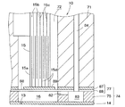
記録ヘッド10は、図2に示すように、例えばプラスチックからなる箱体状のケース71の収納室72内に、櫛歯状の圧電振動子15が一方の開口から挿入されて櫛歯状先端部15aが他方の開口に臨んでいる。その他方の開口側のケース71の表面(下面)には流路ユニット74が接合され、櫛歯状先端部15aは、それぞれ流路ユニット74の所定部位に当接固定されている。
As shown in FIG. 2, the
圧電振動子15は、圧電体15bを挟んで共通内部電極15cと個別内部電極15dとを交互に積層した板状の振動子板を、ドット形成密度に対応させて櫛歯状に切断して構成してある。そして、共通内部電極15cと個別内部電極15dとの間に電位差を与えることにより、各圧電振動子15は、積層方向と直交する振動子長手方向に伸縮する。
The
流路ユニット74は、流路形成板75を間に挟んでノズルプレート14と弾性板77を両側に積層することにより構成されている。
The
流路形成板75は、ノズルプレート14に複数開設したノズル開口13とそれぞれ連通して圧力発生室隔壁を隔てて列設された複数の圧力発生室16と、各圧力発生室16の少なくとも一端に連通する複数のインク供給部82と、全インク供給部82が連通する細長い共通インク室83と、が形成された板材である。例えば、シリコンウエハーをエッチング加工することにより、細長い共通インク室83が形成され、共通インク室83の長手方向に沿って圧力発生室16がノズル開口13のピッチに合わせて形成され、各圧力発生室16と共通インク室83との間に溝状のインク供給部82が形成され得る。なお、この場合、圧力発生室16の一端にインク供給部82が接続し、このインク供給部82とは反対側の端部近傍でノズル開口13が位置するように配置されている。また、共通インク室83は、インクカートリッジに貯留されたインクを圧力発生室16に供給するための室であり、その長手方向のほぼ中央にインク供給管84が連通している。
The flow
弾性板77は、ノズルプレート14とは反対側の流路形成板75の面に積層され、ステンレス板87の下面側にPPS等の高分子体フィルムを弾性体膜88としてラミネート加工した二重構造である。そして、圧力発生室16に対応した部分のステンレス板87をエッチング加工して、圧電振動子15を当接固定するためのアイランド部89が形成されている。
The
上記の構成を有する記録ヘッド10では、圧電振動子15を振動子長手方向に伸長させることにより、アイランド部89がノズルプレート14側に押圧され、アイランド部89周辺の弾性体膜88が変形して圧力発生室16が収縮する。また、圧力発生室16の収縮状態から圧電振動子15を長手方向に収縮させると、弾性体膜88の弾性により圧力発生室16が膨張する。圧力発生室16を一旦膨張させてから収縮させることにより、圧力発生室16内のインク圧力が高まって、ノズル開口13からインク滴が吐出される。
In the
すなわち、記録ヘッド10では、圧電振動子15に対する充放電に伴って、対応する圧力室16の容量が変化する。このような圧力室16の圧力変動を利用して、ノズル開口13からインク滴を吐出させたり、メニスカス(ノズル開口13で露出しているインクの自由表面)を微振動させたりすることができる。
That is, in the
なお、上記の縦振動振動モードの圧電振動子15に代えて、いわゆるたわみ振動モードの圧電振動子を用いることも可能である。たわみ振動モードの圧電振動子は、充電による変形で圧力室を収縮させ、放電による変形で圧力室を膨張させる圧電振動子である。たわみ振動モードの圧電振動子を用いる場合、縦振動モードの圧電振動子15を用いる場合と比較して、後述する波形信号の立ち上がりと立ち下がりとの関係が逆になる(正負が反転したものとなる)。
In place of the longitudinal vibration vibration mode
記録ヘッド10は、好ましくは、異なる複数種類の色が記録可能な多色記録ヘッドである。多色記録ヘッドは、複数のヘッドユニットを備えており、各ヘッドユニット毎に使用するインクの種類が設定される。
The
本実施の形態の記録へッド10は、ブラックインクを吐出可能なブラックヘッドユニットと、シアンインクを吐出可能なシアンヘッドユニットと、ライトシアンインクを吐出可能なライトシアンヘッドユニットと、マゼンタインクを吐出可能なマゼンタヘッドユニットと、ライトマゼンタインクを吐出可能なライトマゼンタヘッドユニットと、イエローインクを吐出可能なイエローヘッドユニットとを備える。
The
以上のように構成されたプリンタ1は、記録動作時においてキャリッジ2の主走査に同期させて、記録ヘッド10からインクをインク滴として吐出させる。一方、キャリッジ2の往復移動に連動させてプラテンを回転し、記録紙8を紙送り方向に移動(即ち副走査)させる。この結果、記録紙8には、記録データに基づく画像や文字等が記録される。
The
次に、インクジェット式プリンタの電気的構成について説明する。図3に示すように、本プリンタ1は、プリンタコントローラ23とプリントエンジン24とを備えている。
Next, the electrical configuration of the ink jet printer will be described. As shown in FIG. 3, the
プリンタコントローラ23は、外部インターフェース(外部I/F)25と、各種データを一時的に記憶するRAM26と、制御プログラム等を記憶したROM27と、CPU等を含んで構成された制御部28と、クロック信号(CK)を発生する発振回路29と、記録ヘッド10へ供給するための第1吐出駆動信号(COM1)を発生する第1吐出駆動信号生成回路30aと、記録ヘッド10へ供給するための第2吐出駆動信号(COM2)を発生する第2吐出駆動信号生成回路30bと、各駆動信号や、印刷データ(吐出データ)に基づいて展開されたドットパターンデータ(ビットマップデータ)等をプリントエンジン24に送信する内部インターフェース(内部I/F)31と、を備えている。
The
外部I/F25は、例えば、キャラクタコード、グラフィック関数、イメージデータ等によって構成される印刷データを、図示しないホストコンピュータ等から受信する。また、ビジー信号(BUSY)やアクノレッジ信号(ACK)が、外部I/F25を通じて、ホストコンピュータ等に対して出力される。
The external I /
RAM26は、受信バッファ、中間バッファ、出力バッファ及びワークメモリ(図示せず)を有している。そして、受信バッファは、外部I/F25を介して受信された印刷データを一時的に記憶し、中間バッファは、制御部28により変換された中間コードデータを記憶し、出力バッファは、ドットパターンデータを記憶する。ここで、ドットパターンデータとは、中間コードデータをデコード(翻訳)することにより得られる印字データである。
The
ROM27には、各種データ処理を行わせるための制御プログラム(制御ルーチン)の他に、フォントデータ、グラフィック関数等が記憶されている。
The
制御部28は、ROM27に記憶された制御プログラムに従って各種の制御を行う。例えば、受信バッファ内の印刷データを読み出すと共にこの印刷データを変換して中間コードデータとし、当該中間コードデータを中間バッファに記憶させる。また、制御部28は、中間バッファから読み出した中間コードデータを解析し、ROM27に記憶されているフォントデータ及びグラフィック関数等を参照して、ドットパターンデータに展開(デコード)する。そして、制御部28は、必要な装飾処理を施した後に、このドットパターンデータを出力バッファに記憶させる。各ドットパターンデータは、階調データ(印字データ)として機能するデータであるが、本実施の形態では、淡色インク(ライトシアンインク、ライトマゼンタインク)と濃色インク(ブラックインク、シアンインク、マゼンタインク、イエローインク)とで異なるビットのデータからなる。淡色インク用の各ドットパターンデータは、2連続の2ビットのデータからなる(そのうち、1ビットはダミーデータビットである)。一方、濃色インク用の各ドットパターンデータは、単一の2ビットのデータからなる。以上のように、制御部28は、階調データ設定手段として機能する。
The
さて、記録ヘッド10の1回の主走査により記録可能な1行分のドットパターンデータが得られたならば、当該1行分のドットパターンデータが、出力バッファから内部I/F31を通じて順次記録ヘッド10に出力される。出力バッファから1行分のドットパターンデータが出力されると、展開済みの中間コードデータが中間バッファから消去され、次の中間コードデータについての展開処理が行われる。
When dot pattern data for one line that can be recorded is obtained by one main scan of the
さらに、制御部28は、タイミング信号発生手段の一部を構成し、内部I/F31を通じて記録ヘッド10にラッチ信号(LAT)やチャンネル信号(CH1、CH2)を供給する。これらのラッチ信号やチャンネル信号は、第1吐出駆動信号(COM1)及び第2吐出駆動信号(COM2)を構成するパルス信号の各波形要素の供給開始タイミングを規定する。
Further, the
一方、プリントエンジン24は、紙送り機構としての紙送りモータ35と、キャリッジ送り機構としてのパルスモータ7と、記録ヘッド10の電気駆動系33と、を含んで構成してある。紙送りモータ35は、プラテン34(図1参照)を回転させて記録紙8を移動させ、パルスモータ7は、タイミングベルト6を介してキャリッジ2を走行させる。
On the other hand, the
記録ヘッド10の電気駆動系33は、図3に示すように、第1シフトレジスタ36及び第2シフトレジスタ37からなるシフトレジスタ回路と、第1ラッチ回路39及び第2ラッチ回路40からなるラッチ回路と、デコーダ42と、制御ロジック43と、第1レベルシフタ44及び第2レベルシフタ45と、第1スイッチ回路46及び第2スイッチ回路47と、圧電振動子15とを備えている。
As shown in FIG. 3, the
これらの各シフトレジスタ、各ラッチ回路、デコーダ、各スイッチ回路及び圧電振動子は、それぞれ、図4に示すように、記録ヘッド10の各ノズル開口13毎に設けた第1シフトレジスタ36A〜36N、第2シフトレジスタ37A〜37N、第1ラッチ回路39A〜39N、第2ラッチ回路40A〜40N、テコーダ42A〜42N、第1スイッチ回路46A〜46N、第2スイッチ回路47A〜47N及び圧電振動子15A〜15Nから構成されている。
Each of these shift registers, latch circuits, decoders, switch circuits, and piezoelectric vibrators are provided as
このような電気駆動系33によって、記録ヘッド10は、プリンタコントローラ23からの階調データに基づいてインク滴を吐出する。プリントコントローラ23からの階調データ(SI)は、発振回路29からのクロック信号(CK)に同期して、内部I/F31から第1シフトレジスタ36及び第2シフトレジスタ37にシリアル伝送される。
With such an
ここで、プリンタコントローラ23からの濃色インク用の階調データ(第1階調データ)は、上記したように単一の2ビットのデータである。具体的には、本実施の形態の場合、非記録、中ドット、大ドット、大大大ドットからなる4階調について、非記録が(00)であり、中ドットが(01)であり、大ドットが(10)であり、大大大ドットが(11)で表されている。
Here, the gradation data (first gradation data) for dark ink from the
このような階調データは、各ドット毎、即ち、各ノズル開口13毎に設定される。そして、全てのノズル開口13に関して階調データの2ビットのデータの下位ビットのデータが第1シフトレジスタ36(36A〜36N)に入力され、全てのノズル開口13に関して当該2ビットのデータの上位ビットのデータが第2シフトレジスタ37(37A〜37N)に入力される。
Such gradation data is set for each dot, that is, for each
図3に示すように、第1シフトレジスタ36には、第1ラッチ回路39が電気的に接続されている。同様に、第2シフトレジスタ37には、第2ラッチ回路40が電気的に接続されている。そして、プリントコントローラ23からのラッチ信号(LAT)が各ラッチ回路39,40に入力されると、第1ラッチ回路39は前記2ビットのデータの下位ビットのデータをラッチし、第2ラッチ回路40は前記2ビットのデータの上位ビットをラッチする。
As shown in FIG. 3, a
このように、第1シフトレジスタ36及び第1ラッチ回路39からなる回路ユニットと、第2シフトレジスタ37及び第2ラッチ回路40からなる回路ユニットは、それぞれが記憶回路として機能する。すなわち、これらの回路ユニットは、デコーダ42に入力される前の階調データを、2ビット毎に、一時的に記憶する。
As described above, the circuit unit including the
各ラッチ回路39、40でラッチされたビットデータは、デコーダ42A〜42Nに入力される。デコーダ42は、単一の2ビットのデータ(第1階調データ)を翻訳して第1パルス選択データ及び第2パルス選択データ(パルス選択情報)を生成する。第1パルス選択データ及び第2パルス選択データは、本実施の形態ではそれぞれ5ビットで構成され、各ビットは各駆動信号(COM1、COM2)を構成する各波形要素に対応している。そして、各ビットの内容(例えば、(0),(1))に応じて、圧電振動子15に対する波形要素の供給/非供給が選択されるようになっている。なお、各駆動信号(COM1、COM2)及び波形要素の供給についての詳細は、後述される。
The bit data latched by the
一方、プリンタコントローラ23からの淡色インク用の階調データ(第2階調データ)は、上記したように2連続の2ビットのデータである。具体的には、本実施の形態の場合、非記録、小ドット、中ドット、大ドット、大大ドット、大大大ドットからなる6階調について、非記録が(00)(00)であり、小ドットが(01)(00)であり、中ドットが(00)(01)であり、大ドットが(00)(10)であり、大大ドットが(01)(01)であり、大大大ドットが(00)(11)で表されている。ここで、「大大ドット」及び「大大大ドット」と表現されているのは、それぞれ、「大ドット」のために用いられるパルスを2つ用いる態様、及び、「大ドット」のために用いられるパルスを3つ用いる態様に対応している(信号の電圧が2倍あるいは3倍という意味ではない)。
On the other hand, the gradation data (second gradation data) for light color ink from the
このような階調データは、各ドット毎、即ち、各ノズル開口13毎に設定される。そして、全てのノズル開口13に関して階調データの前半の2ビットのデータの下位ビットのデータが第1シフトレジスタ36(36A〜36N)に入力され、全てのノズル開口13に関して当該2ビットのデータの上位ビットのデータが第2シフトレジスタ37(37A〜37N)に入力される。(もっとも、本実施の形態における当該2ビットのデータの上位ビットは、常に「0」のダミーデータビットである。)
図3に示すように、第1シフトレジスタ36には、第1ラッチ回路39が電気的に接続されている。同様に、第2シフトレジスタ37には、第2ラッチ回路40が電気的に接続されている。そして、プリントコントローラ23からのラッチ信号(LAT)が各ラッチ回路39,40に入力されると、第1ラッチ回路39は前記2ビットのデータの下位ビットのデータをラッチし、第2ラッチ回路40は前記2ビットのデータの上位ビットをラッチする。
Such gradation data is set for each dot, that is, for each
As shown in FIG. 3, a
このように、第1シフトレジスタ36及び第1ラッチ回路39からなる回路ユニットと、第2シフトレジスタ37及び第2ラッチ回路40からなる回路ユニットは、それぞれが記憶回路として機能する。すなわち、これらの回路ユニットは、デコーダ42に入力される前の階調データを、2ビット毎に、一時的に記憶する。
As described above, the circuit unit including the
続いて、全てのノズル開口13に関して前記階調データの後半の2ビットのデータの下位ビットのデータが第1シフトレジスタ36(36A〜36N)に入力され、全てのノズル開口13に関して当該2ビットのデータの上位ビットのデータが第2シフトレジスタ37(37A〜37N)に入力される。
Subsequently, the low-order bit data of the latter two bits of the gradation data for all the
そして、前半の2ビットのデータに関する処理と同様に、プリントコントローラ23からの次のラッチ信号(LAT)が各ラッチ回路39,40に入力されると、第1ラッチ回路39は前記後半の2ビットのデータの下位ビットのデータをラッチし、第2ラッチ回路40は前記後半の2ビットのデータの上位ビットをラッチする。すなわち、1ドット(画素)あたりの制御のために2つのラッチ信号が利用される。
When the next latch signal (LAT) from the
各ラッチ回路39、40でラッチされたビットデータは、デコーダ42A〜42Nに入力される。デコーダ42は、2連続の2ビットのデータ(階調データ)を翻訳して第1パルス選択データ及び第2パルス選択データ(パルス選択情報)を生成する。第1パルス選択データ及び第2パルス選択データは、本実施の形態ではそれぞれ5ビットで構成され、各ビットは各駆動信号(COM1、COM2)を構成する各波形要素に対応している。そして、各ビットの内容(例えば、(0),(1))に応じて、圧電振動子15に対する波形要素の供給/非供給が選択されるようになっている。なお、各駆動信号(COM1、COM2)及び波形要素の供給についての詳細は、後述される。
The bit data latched by the
なお、デコーダ42には、制御ロジック43からのタイミング信号も入力される。制御ロジック43は、制御部28と共にタイミング信号発生手段として機能し、ラッチ信号(LAT)やチャンネル信号(CH1、CH2)に基づいてタイミング信号を発生する。
Note that the
デコーダ42によって翻訳された第1パルス選択データは、上位ビット側から順に、タイミング信号によって規定されるタイミングが到来する毎に第1レベルシフタ44に入力される。例えば、記録周期における最初のタイミングでは第1パルス選択データの最上位ビットのデータが第1レベルシフタ44に入力され、2番目のタイミングでは第1パルス選択データにおける2番目のビットのデータが第1レベルシフタ44に入力される。
The first pulse selection data translated by the
同様に、デコーダ42によって翻訳された第2パルス選択データは、上位ビット側から順に、タイミング信号によって規定されるタイミングが到来する毎に第2レベルシフタ45に入力される。例えば、記録周期における最初のタイミングでは第2パルス選択データの最上位ビットのデータが第2レベルシフタ45に入力され、2番目のタイミングでは第2パルス選択データにおける2番目のビットのデータが第2レベルシフタ45に入力される。
Similarly, the second pulse selection data translated by the
第1レベルシフタ44及び第2レベルシフタ45は、電圧増幅器として機能し、パルス選択データが「1」の場合には、第1スイッチ回路46及び第2スイッチ回路47を駆動できる電圧、例えば数十ボルト程度の電圧に昇圧された電気信号を出力する。
The
第1レベルシフタ44で昇圧された「1」のパルス選択データは、駆動パルス生成手段として機能する第1スイッチ回路46に供給される。この第1スイッチ回路46は、印字データの翻訳により生成された第1パルス選択データに基づき、第1吐出駆動信号(COM1)に含まれる波形要素を選択して駆動パルスを生成すると共に、当該駆動パルスを圧電振動子15に供給するものである。従って、第1スイッチ回路46の入力側には、第1吐出駆動信号生成回路30aからの駆動信号(COM1)が供給されるようになっており、その出力側には圧電振動子15が接続されている。
The pulse selection data “1” boosted by the
第1パルス選択データは、第1スイッチ回路46の作動を制御する。例えば、第1スイッチ回路46に加わるパルス選択データが「1」である期間中は、第1スイッチ回路46が接続状態になり、第1吐出駆動信号COM1の駆動パルスが圧電振動子15に供給される。この結果、圧電振動子15の電位レベルが変化する。
The first pulse selection data controls the operation of the
一方、第1スイッチ回路46に加わるパルス選択データが「0」の期間中は、第1レベルシフタ44から第1スイッチ回路46を作動させる電気信号が出力されない。このため、第1スイッチ回路46が切断状態になり、駆動信号の駆動パルスが圧電振動子15に供給されない。
On the other hand, during the period when the pulse selection data applied to the
一方、第2レベルシフタ45で昇圧された「1」のパルス選択データは、駆動パルス生成手段として機能する第2スイッチ回路47に供給される。この第2スイッチ回路47は、印字データの翻訳により生成された第2パルス選択データに基づき、第2吐出駆動信号(COM2)に含まれる波形要素を選択して駆動パルスを生成すると共に、当該駆動パルスを圧電振動子15に供給するものである。従って、第2スイッチ回路47の入力側には、第2吐出駆動信号生成回路30bからの駆動信号(COM2)が供給されるようになっており、その出力側には圧電振動子15が接続されている。
On the other hand, the pulse selection data “1” boosted by the
第2パルス選択データは、第2スイッチ回路47の作動を制御する。例えば、第2スイッチ回路47に加わるパルス選択データが「1」である期間中は、第2スイッチ回路47が接続状態になり、第2吐出駆動信号COM2の駆動パルスが圧電振動子15に供給される。この結果、圧電振動子15の電位レベルが変化する。
The second pulse selection data controls the operation of the
一方、第2スイッチ回路47に加わるパルス選択データが「0」の期間中は、第2レベルシフタ45から第2スイッチ回路47を作動させる電気信号が出力されない。このため、第2スイッチ回路47が切断状態になり、駆動信号の駆動パルスが圧電振動子15に供給されない。
On the other hand, during the period when the pulse selection data applied to the
次に、第1吐出駆動信号生成回路30aが生成する第1吐出駆動信号(COM1)と、第2吐出駆動信号生成回路30bが生成する第2吐出駆動信号(COM2)と、これらの駆動信号によるインク滴の吐出制御について詳細に説明する。
Next, the first ejection drive signal (COM1) generated by the first ejection drive
図5に示す第1吐出駆動信号COM1は、期間T11に配置された第1パルス波形信号PS1と、期間T12に配置された第2パルス波形信号PS2と、期間T13に配置された第3パルス波形信号PS3と、を一連に接続してあり、記録周期T1で繰り返し発生するパルス列波形信号である。本実施の形態では、各期間T11、T12及びT13は同一時間として設定されている。なお、期間T14及びT15には、パルス波形信号は含まれておらず、例えば調整要素として利用され得る。 The first ejection drive signal COM1 shown in FIG. 5 includes a first pulse waveform signal PS1 arranged in the period T11, a second pulse waveform signal PS2 arranged in the period T12, and a third pulse waveform arranged in the period T13. The signal PS3 is connected in series and is a pulse train waveform signal repeatedly generated at the recording cycle T1. In the present embodiment, the periods T11, T12, and T13 are set as the same time. The periods T14 and T15 do not include a pulse waveform signal and can be used as an adjustment element, for example.
第1パルス波形信号PS1及び第3パルス波形信号PS3は、何れも同じ波形形状であり、それぞれ大量のインク滴の吐出を行うための信号である。 Both the first pulse waveform signal PS1 and the third pulse waveform signal PS3 have the same waveform shape, and are signals for discharging a large amount of ink droplets.
すなわち、これらの各パルス波形信号PS1,PS3は、中間電位VMから勾配θ11に沿って最高電位VHまで電位を上昇する第1充電要素P11と、この最高電位VHを短い時間維持する第1ホールド要素P12と、最高電位VHから急勾配θ12に沿って最低電位VLまで極く短時間で電位を下降させる第1放電要素P13と、最低電位を維持する第2ホールド要素P14と、最低電位VLから勾配θ13に沿って中間電位VMまで電位を上昇させる第2充電要素P15とから構成される。 That is, each of these pulse waveform signals PS1 and PS3 includes a first charging element P11 that increases the potential from the intermediate potential VM to the maximum potential VH along the gradient θ11, and a first hold element that maintains this maximum potential VH for a short time. P12, a first discharge element P13 that drops the potential from the highest potential VH to the lowest potential VL along the steep slope θ12 in a very short time, a second hold element P14 that maintains the lowest potential, and a slope from the lowest potential VL The second charging element P15 is configured to increase the potential to the intermediate potential VM along θ13.
各パルス波形信号PS1,PS3が圧電振動子15に供給されると、約7plのインク滴がノズル開口13から吐出される。
When the pulse waveform signals PS1 and PS3 are supplied to the
より具体的には、第1充電要素P11が供給されて圧電振動子15が中間電位VMから充電されることにより、圧力発生室16の容積は、基準容積から最大容積まで膨張する。そして、第1放電要素P13により、圧力発生室16は最小容積まで急激に収縮する。この圧力発生室16の収縮状態は第2ホールド要素P14が供給されている期間に亘って維持される。この圧力発生室16の急激な収縮及び収縮状態の保持により、圧力発生室16内のインク圧力が急速に高まりノズル開口13からはインク滴が吐出する。このとき吐出されるインク滴の量は、7pl程度となっている。そして、第2充電要素P15により、メニスカスの振動を短時間で収束させるべく圧力発生室16を膨張復帰させる。
More specifically, when the first charging element P11 is supplied and the
第2パルス波形信号PS2は、ノズル開口13部分のインクのメニスカスを微振動させるが、インク滴の吐出は行わない印字内微振動動作のための信号である。
The second pulse waveform signal PS2 is a signal for the fine vibration operation in the print which causes the ink meniscus in the
すなわち、第2パルス波形信号PS2は、中間電位VMから勾配θ21に沿って第2高電位VH2(<VH)まで電位を上昇する第1充電要素P21と、この第2高電位VH2を短い時間維持する第1ホールド要素P22と、第2高電位VH2から勾配θ22に沿って中間電位VMまで電位を降下させる第1放電要素P23とから構成される。 That is, the second pulse waveform signal PS2 maintains the second high potential VH2 for a short time, and the first charging element P21 that increases the potential from the intermediate potential VM to the second high potential VH2 (<VH) along the gradient θ21. And a first discharge element P23 that drops the potential from the second high potential VH2 to the intermediate potential VM along the gradient θ22.
第2パルス波形信号PS2が圧電振動子15に供給されると、ノズル開口13におけるインクのメニスカスが微振動される。
When the second pulse waveform signal PS2 is supplied to the
一方、図5に示す第2吐出駆動信号COM2は、前記期間T11に配置された第4パルス波形信号PS4と、前記期間T12に配置された第5パルス波形信号PS5と、前記期間T13に配置された第6パルス波形信号PS6と、を一連に接続してあり、前記記録周期T1で繰り返し発生するパルス列波形信号である。 On the other hand, the second ejection drive signal COM2 shown in FIG. 5 is arranged in the fourth pulse waveform signal PS4 arranged in the period T11, the fifth pulse waveform signal PS5 arranged in the period T12, and the period T13. The sixth pulse waveform signal PS6 is connected in series and is a pulse train waveform signal repeatedly generated at the recording cycle T1.
第4パルス波形信号PS4は、中量のインク滴の吐出を行うための信号である。 The fourth pulse waveform signal PS4 is a signal for ejecting a medium amount of ink droplets.
すなわち、第4パルス波形信号PS4は、中間電位VMから勾配θ41に沿って最高電位VHまで電位を上昇する第1充電要素P41と、この最高電位VHを短い時間維持する第1ホールド要素P42と、最高電位VHから勾配θ42に沿って中間電位VMまで短時間で電位を下降させる第1放電要素P43と、中間電位VMを維持する第2ホールド要素P44と、中間電位VMから勾配θ43に沿って第2高電位VH2(<VH)まで電位を上昇する第2充電要素P45と、第2高電位VH2を維持する第3ホールド要素P46と、第2高電位VH2から勾配θ44に沿って最低電位VLまで電位を下降させる第2放電要素P47と、最低電位を維持する第3ホールド要素P48と、最低電位VLから勾配θ45に沿って中間電位VMまで電位を上昇させる第3充電要素P49とから構成される。 That is, the fourth pulse waveform signal PS4 includes a first charging element P41 that increases the potential from the intermediate potential VM to the maximum potential VH along the gradient θ41, a first hold element P42 that maintains this maximum potential VH for a short time, A first discharge element P43 that drops the potential from the highest potential VH along the gradient θ42 to the intermediate potential VM in a short time, a second hold element P44 that maintains the intermediate potential VM, and a second discharge element P44 that maintains the intermediate potential VM along the gradient θ43. 2 a second charging element P45 that increases the potential to the high potential VH2 (<VH), a third hold element P46 that maintains the second high potential VH2, and a minimum potential VL along the gradient θ44 from the second high potential VH2. The second discharge element P47 that lowers the potential, the third hold element P48 that maintains the lowest potential, and the potential from the lowest potential VL to the intermediate potential VM along the gradient θ45. And a third charging element P49 for raising the power.
第4パルス波形信号PS4が圧電振動子15に供給されると、約3plのインク滴がノズル開口13から吐出される。
When the fourth pulse waveform signal PS4 is supplied to the
より具体的には、第1充電要素P41が供給されて圧電振動子15が中間電位VMから充電されることにより、圧力発生室16の容積は、基準容積から最大容積まで膨張する。そして、第1放電要素P43により、圧力発生室16は収縮する。この圧力発生室16の収縮状態は第2ホールド要素P44が供給されている期間に亘って維持される。この圧力発生室16の収縮及び収縮状態の保持により、圧力発生室16内のインク圧力が急速に高まりノズル開口13からはインク滴が吐出する。このとき吐出されるインク滴の量は、3pl程度となっている。そして、第2充電要素P45〜第3充電要素P49により、メニスカスの振動が短時間で収束されるようになっている。
More specifically, when the first charging element P41 is supplied and the
第5パルス波形信号PS5は、第1パルス波形信号PS1及び第3パルス波形信号PS3と同じ波形形状を有する信号である。第5パルス波形信号PS5が圧電振動子15に供給されると、約7plのインク滴がノズル開口13から吐出される。
The fifth pulse waveform signal PS5 is a signal having the same waveform shape as the first pulse waveform signal PS1 and the third pulse waveform signal PS3. When the fifth pulse waveform signal PS5 is supplied to the
第6パルス波形信号PS6は、小量のインク滴の吐出を行うための信号である。 The sixth pulse waveform signal PS6 is a signal for ejecting a small amount of ink droplets.
すなわち、第6パルス波形信号PS6は、中間電位VMから勾配θ61に沿って最高電位VHまで電位を上昇する第1充電要素P61と、この最高電位VHを短い時間維持する第1ホールド要素P62と、最高電位VHから勾配θ62に沿って中間電位VMまで短時間で電位を下降させる第1放電要素P63と、中間電位VMを維持する第2ホールド要素P64と、中間電位VMから勾配θ63に沿って再び最高電位VHまで電位を上昇する第2充電要素P65と、最高電位VHを維持する第3ホールド要素P66と、最高電位VHから勾配θ64に沿って最低電位VLまで電位を下降させる第2放電要素P67と、最低電位を維持する第3ホールド要素P68と、最低電位VLから勾配θ65に沿って中間電位VMまで電位を上昇させる第3充電要素P69とから構成される。 That is, the sixth pulse waveform signal PS6 includes a first charging element P61 that increases the potential from the intermediate potential VM to the maximum potential VH along the gradient θ61, a first hold element P62 that maintains this maximum potential VH for a short time, A first discharge element P63 that drops the potential from the highest potential VH along the gradient θ62 to the intermediate potential VM in a short time, a second hold element P64 that maintains the intermediate potential VM, and again from the intermediate potential VM along the gradient θ63. A second charging element P65 that increases the potential to the maximum potential VH, a third hold element P66 that maintains the maximum potential VH, and a second discharge element P67 that decreases the potential from the maximum potential VH to the minimum potential VL along the gradient θ64. A third hold element P68 that maintains the lowest potential, and a third charge element that raises the potential from the lowest potential VL to the intermediate potential VM along the gradient θ65. And an electric element P69.
第6パルス波形信号PS6が圧電振動子15に供給されると、約1.5plのインク滴がノズル開口13から吐出される。
When the sixth pulse waveform signal PS 6 is supplied to the
より具体的には、第1充電要素P61が供給されて圧電振動子15が中間電位VMから充電されることにより、圧力発生室16の容積は、基準容積から最大容積まで膨張する。そして、第1放電要素P63により、圧力発生室16は収縮する。この圧力発生室16の収縮状態は第2ホールド要素P64が供給されている期間に亘って維持される。この圧力発生室16の収縮及び収縮状態の保持により、圧力発生室16内のインク圧力が急速に高まりノズル開口13からはインク滴が吐出する。このとき吐出されるインク滴の量は、1.5pl程度となっている。そして、第2充電要素P65〜第3充電要素P69により、メニスカスの振動が短時間で収束されるようになっている。
More specifically, when the first charging element P61 is supplied and the
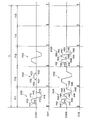
そして、図6及び図7に示すように、圧電振動子15に供給するパルス波形信号を適宜に選択することによって、階調制御を行うことができる。すなわち、第2パルス波形信号PS2を駆動パルスとして供給することで非記録の微振動を行い(図6及び図7)、第6パルス波形信号PS6を駆動パルスとして供給することで小ドットの記録を行い(図7)、第4パルス波形信号PS4を駆動パルスとして供給することで中ドットの記録を行い(図6及び図7)、第5パルス波形信号PS5を駆動パルスとして供給することで大ドットの記録を行い(図6及び図7)、第1パルス波形信号PS1及び第3パルス波形信号PS3を駆動パルスとして供給することで大大ドットの記録を行い(図7)、第1パルス波形信号PS1、第5パルス波形信号PS5及び第3パルス波形信号PS3を駆動パルスとして供給することで大大大ドットの記録を行うことができる(図6及び図7)。この時、3つのパルス波形信号PS1,PS3,PS5は、互いに等間隔に出現するようになっている。
As shown in FIGS. 6 and 7, gradation control can be performed by appropriately selecting a pulse waveform signal to be supplied to the
ここで、濃色インクに関して、非吐出(非記録)のドットパターンデータ(階調情報(00))、中ドットのドットパターンデータ(階調情報(01))、大ドットのドットパターンデータ(階調情報(10))及び大大大ドットのドットパターンデータ(階調情報(11))に応じて生成されるパルス選択データについて、図6を参照しながら具体的に説明する。 Here, regarding dark ink, non-ejection (non-recording) dot pattern data (gradation information (00)), medium dot dot pattern data (gradation information (01)), and large dot dot pattern data (floor). The pulse selection data generated according to the tone information (10)) and the dot pattern data of large and large dots (gradation information (11)) will be specifically described with reference to FIG.
デコーダ42は、この場合、各ドットパターンデータの単一の2ビットのデータに応じて、各5ビットの第1パルス選択データ及び第2パルス選択データを生成する。具体的には、各ドットパターンデータが(00)の場合、第1パルス選択データ(01000)及び第2パルス選択データ(00000)が生成され、各ドットパターンデータが(01)の場合、第1パルス選択データ(00000)及び第2パルス選択データ(10000)が生成され、各ドットパターンデータが(10)の場合、第1パルス選択データ(00000)及び第2パルス選択データ(01000)が生成され、各ドットパターンデータが(11)の場合、第1パルス選択データ(10100)及び第2パルス選択データ(01000)が生成される。
In this case, the
5ビットの第1パルス選択データの最上位ビットが第1パルス波形信号PS1に対応し、2番目のビットが第2パルス波形信号PS2に対応し、3番目のビットが第3パルス波形信号PS3に対応している。 The most significant bit of the 5-bit first pulse selection data corresponds to the first pulse waveform signal PS1, the second bit corresponds to the second pulse waveform signal PS2, and the third bit corresponds to the third pulse waveform signal PS3. It corresponds.
また、5ビットの第2パルス選択データの最上位ビットが第4パルス波形信号PS4に対応し、2番目のビットが第5パルス波形信号PS5に対応し、3番目のビットが第6パルス波形信号PS6に対応している。 The most significant bit of the 5-bit second pulse selection data corresponds to the fourth pulse waveform signal PS4, the second bit corresponds to the fifth pulse waveform signal PS5, and the third bit corresponds to the sixth pulse waveform signal. Supports PS6.
そして、第1パルス選択データの最上位ビットが「1」の場合には期間T11の始端に対応する最初のタイミング信号(ラッチ信号)から期間T12の始端に対応する2番目のタイミング信号(CH信号)までの間第1スイッチ回路46(駆動パルス供給手段)が接続状態になる。また、2番目のビットが「1」の場合には、2番目のタイミング信号から期間T13の始端に対応する3番目のタイミング信号(CH信号)までの間第1スイッチ回路46が接続状態になる。同様に、3番目のビットが「1」の場合には、3番目のタイミング信号から期間T14の始端に対応する4番目のタイミング信号(ラッチ信号)までの間第1スイッチ回路46が接続状態になる。4番目のビットが「1」の場合には、4番目のタイミング信号から期間T15の始端に対応する5番目のタイミング信号(CH信号)までの間第1スイッチ回路46が接続状態になる。5番目のビットが「1」の場合には、5番目のタイミング信号から次の印刷周期T1における期間T11の始端に対応するタイミング信号(ラッチ信号)までの間第1スイッチ回路46が接続状態になる。
When the most significant bit of the first pulse selection data is “1”, the second timing signal (CH signal) corresponding to the start end of the period T12 is changed from the first timing signal (latch signal) corresponding to the start end of the period T11. ) Until the first switch circuit 46 (drive pulse supply means) is connected. When the second bit is “1”, the
一方、第2パルス選択データの最上位ビットが「1」の場合には期間T11の始端に対応する最初のタイミング信号(ラッチ信号)から期間T12の始端に対応する2番目のタイミング信号(CH信号)までの間第2スイッチ回路47(駆動パルス供給手段)が接続状態になる。また、2番目のビットが「1」の場合には、2番目のタイミング信号から期間T13の始端に対応する3番目のタイミング信号(CH信号)までの間第2スイッチ回路47が接続状態になる。同様に、3番目のビットが「1」の場合には、3番目のタイミング信号から期間T14の始端に対応する4番目のタイミング信号(ラッチ信号)までの間第2スイッチ回路47が接続状態になる。4番目のビットが「1」の場合には、4番目のタイミング信号から期間T15の始端に対応する5番目のタイミング信号(CH信号)までの間第2イッチ回路47が接続状態になる。5番目のビットが「1」の場合には、5番目のタイミング信号から次の印刷周期T1における期間T11の始端に対応するタイミング信号(ラッチ信号)までの間第2スイッチ回路47が接続状態になる。
On the other hand, when the most significant bit of the second pulse selection data is “1”, the second timing signal (CH signal) corresponding to the start end of the period T12 is changed from the first timing signal (latch signal) corresponding to the start end of the period T11. ) Until the second switch circuit 47 (drive pulse supply means) is connected. When the second bit is “1”, the
これにより、非記録のドットパターンデータに基づき、対応する圧電振動子15には、第2パルス波形信号PS2が供給される。また、中ドットのドットパターンデータに基いて、第4パルス波形信号PS4が供給される。また、大ドットのドットパターンデータに基いて、第5パルス波形信号PS5が供給される。また、大大大ドットのドットパターンデータに基いて、第1パルス波形信号PS1、第5パルス波形信号PS5及び第3パルス波形信号PS3が供給される(図6参照)。
Accordingly, the second pulse waveform signal PS2 is supplied to the corresponding
その結果、非記録のドットパターンデータに対応して、ノズル開口13のインクが微振動される。また、中ドットのドットパターンデータに対応して、ノズル開口13からは約3plのインク滴が1回吐出し、記録紙8上に約3plのインク滴による中ドットが形成される。また、大ドットのドットパターンデータに対応して、ノズル開口13からは約7plのインク滴が1回吐出し、記録紙8上に約7plのインク滴による中ドットが形成される。また、大大大ドットのドットパターンデータに対応して、ノズル開口13からは約7plのインク滴が3回吐出し、記録紙8上に合計21plのインク滴による大大大ドットが形成される。
As a result, the ink in the
一方、淡色インクに関して、非吐出(非記録)のドットパターンデータ(階調情報(00)(00))、小ドットのドットパターンデータ(階調情報(01)(00))、中小ドットのドットパターンデータ(階調情報(00)(01))、大ドットのドットパターンデータ(階調情報(00)(10))、大大ドットのドットパターンデータ(階調情報(01)(01))及び大大大ドットのドットパターンデータ(階調情報(00)(11))に応じて生成されるパルス選択データについて、図7を参照しながら具体的に説明する。 On the other hand, with respect to light color ink, non-ejection (non-recording) dot pattern data (gradation information (00) (00)), small dot dot pattern data (gradation information (01) (00)), and medium and small dot dots Pattern data (gradation information (00) (01)), dot pattern data for large dots (gradation information (00) (10)), dot pattern data for large dots (gradation information (01) (01)), and The pulse selection data generated according to the dot pattern data of large and large dots (gradation information (00) (11)) will be specifically described with reference to FIG.
デコーダ42は、この場合、各ドットパターンデータの2連続の2ビットのデータに応じて、各5ビットの第1パルス選択データ及び第2パルス選択データを生成する。具体的には、各ドットパターンデータが(00)(00)の場合、第1パルス選択データ(01000)及び第2パルス選択データ(00000)が生成され、各ドットパターンデータが(01)(00)の場合、第1パルス選択データ(00000)及び第2パルス選択データ(00100)が生成され、各ドットパターンデータが(00)(01)の場合、第1パルス選択データ(00000)及び第2パルス選択データ(10000)が生成され、各ドットパターンデータが(00)(10)の場合、第1パルス選択データ(00000)及び第2パルス選択データ(01000)が生成され、各ドットパターンデータが(01)(01)の場合、第1パルス選択データ(10100)及び第2パルス選択データ(00000)が生成され、各ドットパターンデータが(00)(11)の場合、第1パルス選択データ(10100)及び第2パルス選択データ(01000)が生成される。
In this case, the
5ビットの第1パルス選択データの最上位ビットが第1パルス波形信号PS1に対応し、2番目のビットが第2パルス波形信号PS2に対応し、3番目のビットが第3パルス波形信号PS3に対応している。 The most significant bit of the 5-bit first pulse selection data corresponds to the first pulse waveform signal PS1, the second bit corresponds to the second pulse waveform signal PS2, and the third bit corresponds to the third pulse waveform signal PS3. It corresponds.
また、5ビットの第2パルス選択データの最上位ビットが第4パルス波形信号PS4に対応し、2番目のビットが第5パルス波形信号PS5に対応し、3番目のビットが第6パルス波形信号PS6に対応している。 The most significant bit of the 5-bit second pulse selection data corresponds to the fourth pulse waveform signal PS4, the second bit corresponds to the fifth pulse waveform signal PS5, and the third bit corresponds to the sixth pulse waveform signal. Supports PS6.
そして、第1パルス選択データの最上位ビットが「1」の場合には期間T11の始端に対応する最初のタイミング信号(ラッチ信号)から期間T12の始端に対応する2番目のタイミング信号(CH信号)までの間第1スイッチ回路46(駆動パルス供給手段)が接続状態になる。また、2番目のビットが「1」の場合には、2番目のタイミング信号から期間T13の始端に対応する3番目のタイミング信号(CH信号)までの間第1スイッチ回路46が接続状態になる。同様に、3番目のビットが「1」の場合には、3番目のタイミング信号から期間T14の始端に対応する4番目のタイミング信号(ラッチ信号)までの間第1スイッチ回路46が接続状態になる。4番目のビットが「1」の場合には、4番目のタイミング信号から期間T15の始端に対応する5番目のタイミング信号(CH信号)までの間第1スイッチ回路46が接続状態になる。5番目のビットが「1」の場合には、5番目のタイミング信号から次の印刷周期T1における期間T11の始端に対応するタイミング信号(ラッチ信号)までの間第1スイッチ回路46が接続状態になる。
When the most significant bit of the first pulse selection data is “1”, the second timing signal (CH signal) corresponding to the start end of the period T12 is changed from the first timing signal (latch signal) corresponding to the start end of the period T11. ) Until the first switch circuit 46 (drive pulse supply means) is connected. When the second bit is “1”, the
一方、第2パルス選択データの最上位ビットが「1」の場合には期間T11の始端に対応する最初のタイミング信号(ラッチ信号)から期間T12の始端に対応する2番目のタイミング信号(CH信号)までの間第2スイッチ回路47(駆動パルス供給手段)が接続状態になる。また、2番目のビットが「1」の場合には、2番目のタイミング信号から期間T13の始端に対応する3番目のタイミング信号(CH信号)までの間第2スイッチ回路47が接続状態になる。同様に、3番目のビットが「1」の場合には、3番目のタイミング信号から期間T14の始端に対応する4番目のタイミング信号(ラッチ信号)までの間第2スイッチ回路47が接続状態になる。4番目のビットが「1」の場合には、4番目のタイミング信号から期間T15の始端に対応する5番目のタイミング信号(CH信号)までの間第2イッチ回路47が接続状態になる。5番目のビットが「1」の場合には、5番目のタイミング信号から次の印刷周期T1における期間T11の始端に対応するタイミング信号(ラッチ信号)までの間第2スイッチ回路47が接続状態になる。
On the other hand, when the most significant bit of the second pulse selection data is “1”, the second timing signal (CH signal) corresponding to the start end of the period T12 is changed from the first timing signal (latch signal) corresponding to the start end of the period T11. ) Until the second switch circuit 47 (drive pulse supply means) is connected. When the second bit is “1”, the
これにより、非記録のドットパターンデータに基づき、対応する圧電振動子15には、第2パルス波形信号PS2が供給される。また、小ドットのドットパターンデータに基づき、対応する圧電振動子15には、第6パルス波形信号PS6が供給される。また、中ドットのドットパターンデータに基いて、第4パルス波形信号PS4が供給される。また、大ドットのドットパターンデータに基いて、第5パルス波形信号PS5が供給される。また、大大ドットのドットパターンデータに基いて、第1パルス波形信号PS1及び第3パルス波形信号PS3が供給される。また、大大大ドットのドットパターンデータに基いて、第1パルス波形信号PS1、第5パルス波形信号PS5及び第3パルス波形信号PS3が供給される(図7参照)。
Accordingly, the second pulse waveform signal PS2 is supplied to the corresponding
その結果、非記録のドットパターンデータに対応して、ノズル開口13のインクが微振動される。また、小ドットのドットパターンデータに対応して、ノズル開口13から約1.5plのインク滴が1回吐出し、記録紙8上に小ドットが形成される。また、中ドットのドットパターンデータに対応して、ノズル開口13からは約3plのインク滴が1回吐出し、記録紙8上に約3plのインク滴による中ドットが形成される。また、大ドットのドットパターンデータに対応して、ノズル開口13からは約7plのインク滴が1回吐出し、記録紙8上に約7plのインク滴による中ドットが形成される。また、大大ドットのドットパターンデータに対応して、ノズル開口13からは約7plのインク滴が2回吐出し、記録紙8上に合計14plのインク滴による大大ドットが形成される。また、大大大ドットのドットパターンデータに対応して、ノズル開口13からは約7plのインク滴が3回吐出し、記録紙8上に合計21plのインク滴による大大大ドットが形成される。
As a result, the ink in the
以上のように、本実施の形態によれば、濃色インクの吐出データに基づく階調制御と淡色インクの吐出データに基づく階調制御とが個別に異なる態様で実施され、淡色インクのみについて5パターン以上の階調制御が実現される。すなわち、濃色インクについての不必要な階調制御が実施されないことにより、各種のコストを抑制することができる。 As described above, according to the present embodiment, the gradation control based on the discharge data of dark ink and the gradation control based on the discharge data of light color ink are individually performed in different modes, and only 5 for light color ink. Gradation control over the pattern is realized. That is, various costs can be suppressed because unnecessary gradation control for dark ink is not performed.
また、本実施の形態によれば、淡色インクのための階調データが2連続の2ビットのデータから構成されているため、2ビットの階調データ用の従前の制御回路を利用しつつ、淡色インクについての6パターン(非記録、小、中、大、大大、大大大)の階調制御を実現することができる。 Further, according to the present embodiment, since the gradation data for the light color ink is composed of two continuous 2-bit data, while using the conventional control circuit for the 2-bit gradation data, It is possible to realize gradation control of six patterns (non-recording, small, medium, large, large, large and large) for light color ink.
また、本実施の形態によれば、2つの吐出駆動信号COM1、COM2の間で信号の変化の程度(電位の変化の程度)の均一化が図られているため、駆動信号発生手段等の構成要素の負担が低減されている。これにより、電気回路を含む各構成要素の寿命等が顕著に改善され得る。 In addition, according to the present embodiment, the degree of change in signal (degree of change in potential) is made uniform between the two ejection drive signals COM1 and COM2. The burden on the elements has been reduced. Thereby, the lifetime etc. of each component including an electric circuit can be remarkably improved.
また、本実施の形態では、第1パルス波形信号PS1、第5パルス波形信号PS5及び第3パルス波形信号PS3が同一の波形形状であり、従来より公知のマルチショット(MS)波形と同様であるため、高周波駆動に適している。 In the present embodiment, the first pulse waveform signal PS1, the fifth pulse waveform signal PS5, and the third pulse waveform signal PS3 have the same waveform shape, which is the same as a conventionally known multi-shot (MS) waveform. Therefore, it is suitable for high frequency driving.
また、本実施の形態では、いわゆる大、中、小の3波形が2つの吐出駆動信号COM1、COM2に分けて生成されており、粒状度の高い階調制御を実現することができる。 In the present embodiment, so-called large, medium, and small three waveforms are generated separately for the two ejection drive signals COM1 and COM2, and gradation control with high granularity can be realized.
なお、第1吐出駆動信号生成回路30a及び第2吐出駆動信号生成回路30bは、DAC回路によって形成されてもよいし、アナログ回路によって形成されてもよい。
The first ejection drive
また、以上の実施の形態において、圧力変動手段は圧電振動子15によって構成されているが、圧力室16の圧力を変化させる圧力変動手段は、圧電振動子15に限定されるものではない。例えば、磁歪素子を圧力発生素子として用い、この磁歪素子によって圧力室16を膨張・収縮させて圧力変動を生じさせるようにしてもよいし、発熱素子を圧力発生素子として用い、この発熱素子からの熱で膨張・収縮する気泡によって圧力室16に圧力変動を生じさせるように構成してもよい。
In the above embodiment, the pressure fluctuation means is constituted by the
また、前述のように、プリンタコントローラ23はコンピュータシステムによって構成されているが、コンピュータシステムに前記各要素を実現させるためのプログラム及び当該プログラムを記録したコンピュータ読取り可能な記録媒体201も、本件の保護対象である。
Further, as described above, the
さらに、前記の各要素が、コンピュータシステム上で動作するOS等のプログラムによって実現される場合、当該OS等のプログラムを制御する各種命令を含むプログラム及び当該プログラムを記録した記録媒体202も、本件の保護対象である。 Further, when each of the above elements is realized by a program such as an OS that operates on a computer system, a program including various instructions for controlling the program such as the OS and a recording medium 202 that records the program are also included in the present invention. It is a protection target.
ここで、記録媒体201、202とは、フロッピーディスク(フレキシブルディスク)等の単体として認識できるものの他、各種信号を伝搬させるネットワークをも含む。 Here, the recording media 201 and 202 include not only a floppy disk (flexible disk) that can be recognized as a single unit but also a network that propagates various signals.
なお、以上の説明はインクジェット式記録装置についてなされているが、本発明は、広く液体噴射装置全般を対象としたものである。液体の例としては、インクの他に、グルー、マニキュア、液体電極材料、生体有機物液体等が用いられ得る。更に、本発明は、液晶等の表示体におけるカラーフィルタの製造装置にも適用され得る。 Although the above description has been made with respect to an ink jet recording apparatus, the present invention is intended for a wide range of liquid ejecting apparatuses in general. As an example of the liquid, in addition to ink, glue, nail polish, liquid electrode material, bioorganic liquid, and the like can be used. Furthermore, the present invention can also be applied to an apparatus for manufacturing a color filter in a display body such as a liquid crystal.
1 インクジェット式プリンタ
2 キャリッジ
3 ガイド部材
4 駆動プーリ
5 遊転プーリ
6 タイミングベルト
7 パルスモータ
8 記録紙
10 記録ヘッド
11 インクカートリッジ
12 インク室
13 ノズル開口
14 ノズルプレート
15 圧電振動子
15a 櫛歯状先端部
15b 圧電体
15c 共通内部電極
15d 個別内部電極
16 圧力室
23 プリンタコントローラ
24 プリントエンジン
25 外部インターフェース
26 RAM
27 ROM
28 制御部
29 発振回路
30a 第1吐出駆動信号生成回路
30b 第2吐出駆動信号生成回路
31 内部インターフェース
33 記録ヘッドの電気駆動系
34 プラテン
35 紙送りモータ
36 第1シフトレジスタ
37 第2シフトレジスタ
39 第1ラッチ回路
40 第2ラッチ回路
42 デコーダ
43 制御ロジック
44 第1レベルシフタ
45 第2レベルシフタ
46 第1スイッチ回路
47 第2スイッチ回路
71 ケース
72 収納室
74 流路ユニット
75 流路形成板
77 弾性板
82 インク供給部
83 共通インク室
84 インク供給管
87 ステンレス板
88 弾性体膜
89 アイランド部
DESCRIPTION OF
27 ROM
28
Claims (3)
ノズル開口部分の液体の圧力を変動させる圧力変動手段と、
第1液体用の吐出データに基づいて、複数の第1階調データから一の選択第1階調データを設定する第1階調データ設定手段と、
第2液体用の吐出データに基づいて、複数の第2階調データから一の選択第2階調データを設定する第2階調データ設定手段と、
同一の周期を有する周期信号である第1吐出駆動信号及び第2吐出駆動信号を生成する駆動信号発生手段と、
選択第1階調データまたは選択第2階調データと第1吐出駆動信号と第2吐出駆動信号とに基づいて、圧力変動手段の駆動パルスを生成する駆動パルス生成手段と、
を備え、
複数の第1階調データと複数の第2階調データとは、互いに異なったデータであり、
第1吐出駆動信号は、一周期中において、
所定の大量の液体滴を吐出可能な第1大パルス波形と、
所定の大量の液体滴を吐出可能な第3大パルス波形と、
を有しており、
第2吐出駆動信号は、一周期中において、
所定の中量の液体滴を吐出可能な中パルス波形と、
所定の小量の液体滴を吐出可能な小パルス波形と、
所定の大量の液体滴を吐出可能な第2大パルス波形と、
を有しており、
第1大パルス波形と第2大パルス波形と第3大パルス波形とは、同一の波形を有しており、
第1大パルス波形と第2大パルス波形と第3大パルス波形とは、当該順序で、等間隔に現れるようになっており、
第1階調データ設定手段は、第1液体用の吐出データに基づいて、4段階の第1階調データから一の選択第1階調データを設定するようになっており、
第2階調データ設定手段は、第2液体用の吐出データに基づいて、6段階の第2階調データから一の選択第2階調データを設定するようになっている
ことを特徴とする液体噴射装置。 A head member having a nozzle opening;
Pressure variation means for varying the pressure of the liquid in the nozzle opening,
First gradation data setting means for setting one selected first gradation data from a plurality of first gradation data based on the discharge data for the first liquid;
Second gradation data setting means for setting one selected second gradation data from a plurality of second gradation data based on the discharge data for the second liquid;
Drive signal generating means for generating a first ejection drive signal and a second ejection drive signal which are periodic signals having the same period ;
Drive pulse generating means for generating a drive pulse of the pressure fluctuation means based on the selected first gradation data or the selected second gradation data, the first discharge drive signal, and the second discharge drive signal ;
With
The plurality of first tone data and a plurality of second tone data, Ri Ah in mutually different data,
The first ejection drive signal is in one cycle.
A first large pulse waveform capable of discharging a predetermined large amount of liquid droplets;
A third large pulse waveform capable of discharging a predetermined large amount of liquid droplets;
Have
The second ejection drive signal is
A medium pulse waveform capable of discharging a predetermined medium amount of liquid droplets;
A small pulse waveform capable of ejecting a predetermined small amount of liquid droplets;
A second large pulse waveform capable of discharging a predetermined large amount of liquid droplets;
Have
The first large pulse waveform, the second large pulse waveform, and the third large pulse waveform have the same waveform,
The first large pulse waveform, the second large pulse waveform, and the third large pulse waveform appear at regular intervals in this order,
The first gradation data setting means is configured to set one selected first gradation data from the four stages of first gradation data based on the discharge data for the first liquid.
The second gradation data setting means sets one selected second gradation data from the six gradations of the second gradation data based on the discharge data for the second liquid. A liquid ejecting apparatus.
ノズル開口部分の液体の圧力を変動させる圧力変動手段と、
第1液体用の吐出データに基づいて、複数の第1階調データから一の選択第1階調データを設定する第1階調データ設定手段と、
第2液体用の吐出データに基づいて、複数の第2階調データから一の選択第2階調データを設定する第2階調データ設定手段と、
同一の周期を有する周期信号である第1吐出駆動信号及び第2吐出駆動信号を生成する駆動信号発生手段と、
選択第1階調データまたは選択第2階調データと第1吐出駆動信号と第2吐出駆動信号とに基づいて、圧力変動手段の駆動パルスを生成する駆動パルス生成手段と、
を備え、
複数の第1階調データと複数の第2階調データとは、互いに異なったデータであり、
第1吐出駆動信号は、一周期中において、
所定の大量の液体滴を吐出可能な第1大パルス波形と、
所定の大量の液体滴を吐出可能な第3大パルス波形と、
を有しており、
第2吐出駆動信号は、一周期中において、
所定の中量の液体滴を吐出可能な中パルス波形と、
所定の小量の液体滴を吐出可能な小パルス波形と、
所定の大量の液体滴を吐出可能な第2大パルス波形と、
を有しており、
第1大パルス波形と第2大パルス波形と第3大パルス波形とは、同一の波形を有しており、
第1大パルス波形と第2大パルス波形と第3大パルス波形とは、当該順序で、等間隔に現れるようになっており、
複数の第1階調データは、非噴射用データと、中ドット用データと、第1の大ドット用データと、第3の大ドット用データと、を有しており、
駆動パルス生成手段は、前記第1吐出駆動信号及び前記第2吐出駆動信号に基づいて、
選択第1階調データが非記録用データである時、微振動パルス波形を駆動パルスとし、
選択第1階調データが中ドット用データである時、第2吐出駆動信号の中パルス波形を駆動パルスとし、
選択第1階調データが第1の大ドット用データである時、第2吐出駆動信号の第2大パルス波形を駆動パルスとし、
選択第1階調データが第3の大ドット用データである時、第1吐出駆動信号の第1大パルス波形と第2吐出駆動信号の第2大パルス波形と第1吐出駆動信号の第3大パルス波形とを駆動パルスとするようになっており、
複数の第2階調データは、非噴射用データと、小ドット用データと、中ドット用データと、第1の大ドット用データと、第2の大ドット用データと、第3の大ドット用データと、を有しており、
駆動パルス生成手段は、前記第1吐出駆動信号及び前記第2吐出駆動信号に基づいて、
選択第2階調データが非記録用データである時、微振動パルス波形を駆動パルスとし、
選択第2階調データが小ドット用データである時、第2吐出駆動信号の小パルス波形を駆動パルスとし、
選択第2階調データが中ドット用データである時、第2吐出駆動信号の中パルス波形を駆動パルスとし、
選択第2階調データが第1の大ドット用データである時、第2吐出駆動信号の第2大パルス波形を駆動パルスとし、
選択第2階調データが第2の大ドット用データである時、第1吐出駆動信号の第1大パルス波形と第1吐出駆動信号の第3大パルス波形とを駆動パルスとし、
選択第2階調データが第3の大ドット用データである時、第1吐出駆動信号の第1大パルス波形と第2吐出駆動信号の第2大パルス波形と第1吐出駆動信号の第3大パルス波形とを駆動パルスとするようになっている
ことを特徴とする液体噴射装置。 A head member having a nozzle opening;
Pressure variation means for varying the pressure of the liquid in the nozzle opening,
First gradation data setting means for setting one selected first gradation data from a plurality of first gradation data based on the discharge data for the first liquid;
Second gradation data setting means for setting one selected second gradation data from a plurality of second gradation data based on the discharge data for the second liquid;
Drive signal generating means for generating a first ejection drive signal and a second ejection drive signal, which are periodic signals having the same period ;
Drive pulse generating means for generating a drive pulse of the pressure fluctuation means based on the selected first gradation data or the selected second gradation data, the first discharge drive signal, and the second discharge drive signal ;
With
The plurality of first tone data and a plurality of second tone data, Ri Ah in mutually different data,
The first ejection drive signal is
A first large pulse waveform capable of discharging a predetermined large amount of liquid droplets;
A third large pulse waveform capable of discharging a predetermined large amount of liquid droplets;
Have
The second ejection drive signal is
A medium pulse waveform capable of discharging a predetermined medium amount of liquid droplets;
A small pulse waveform capable of ejecting a predetermined small amount of liquid droplets;
A second large pulse waveform capable of discharging a predetermined large amount of liquid droplets;
Have
The first large pulse waveform, the second large pulse waveform, and the third large pulse waveform have the same waveform,
The first large pulse waveform, the second large pulse waveform, and the third large pulse waveform appear at regular intervals in this order,
The plurality of first gradation data includes non-ejection data, medium dot data, first large dot data, and third large dot data.
The drive pulse generating means is based on the first ejection drive signal and the second ejection drive signal,
When the selected first gradation data is non-recording data, the fine vibration pulse waveform is used as a drive pulse,
When the selected first gradation data is medium dot data, the middle pulse waveform of the second ejection drive signal is used as a drive pulse,
When the selected first gradation data is the first large dot data, the second large pulse waveform of the second ejection drive signal is used as the drive pulse,
When the selected first gradation data is the third large dot data, the first large pulse waveform of the first ejection drive signal, the second large pulse waveform of the second ejection drive signal, and the third of the first ejection drive signal. A large pulse waveform is used as the drive pulse.
The plurality of second gradation data includes non-ejection data, small dot data, medium dot data, first large dot data, second large dot data, and third large dot. Data for
The drive pulse generating means is based on the first ejection drive signal and the second ejection drive signal,
When the selected second gradation data is non-recording data, the fine vibration pulse waveform is used as a drive pulse,
When the selected second gradation data is data for small dots, the small pulse waveform of the second ejection drive signal is used as a drive pulse,
When the selected second gradation data is medium dot data, the middle pulse waveform of the second ejection drive signal is used as the drive pulse,
When the selected second gradation data is the first large dot data, the second large pulse waveform of the second ejection drive signal is used as the drive pulse,
When the selected second gradation data is the second large dot data, the first large pulse waveform of the first ejection drive signal and the third large pulse waveform of the first ejection drive signal are used as drive pulses,
When the selected second gradation data is the third large dot data, the first large pulse waveform of the first ejection drive signal, the second large pulse waveform of the second ejection drive signal, and the third of the first ejection drive signal. A liquid ejecting apparatus, wherein a large pulse waveform is used as a driving pulse .
第2液体用の吐出データは、ライトシアンインク用の吐出データ及びライトマゼンタインク用の吐出データである
ことを特徴とする請求項1または2に記載の液体噴射装置。 The discharge data for the first liquid is discharge data for black ink, discharge data for cyan ink, discharge data for magenta ink, and discharge data for yellow ink.
3. The liquid ejecting apparatus according to claim 1, wherein the discharge data for the second liquid is discharge data for light cyan ink and discharge data for light magenta ink.
Priority Applications (5)
| Application Number | Priority Date | Filing Date | Title |
|---|---|---|---|
| JP2005103561A JP4636372B2 (en) | 2005-03-31 | 2005-03-31 | Liquid ejector |
| US11/393,711 US7500726B2 (en) | 2005-03-31 | 2006-03-31 | Liquid ejecting apparatus driving-signals generation |
| US12/366,505 US7988249B2 (en) | 2005-03-31 | 2009-02-05 | Liquid ejecting apparatus |
| US13/179,943 US8303066B2 (en) | 2005-03-31 | 2011-07-11 | Liquid ejecting apparatus |
| US13/669,237 US20130063509A1 (en) | 2005-03-31 | 2012-11-05 | Liquid ejecting apparatus |
Applications Claiming Priority (1)
| Application Number | Priority Date | Filing Date | Title |
|---|---|---|---|
| JP2005103561A JP4636372B2 (en) | 2005-03-31 | 2005-03-31 | Liquid ejector |
Publications (2)
| Publication Number | Publication Date |
|---|---|
| JP2006281565A JP2006281565A (en) | 2006-10-19 |
| JP4636372B2 true JP4636372B2 (en) | 2011-02-23 |
Family
ID=37108084
Family Applications (1)
| Application Number | Title | Priority Date | Filing Date |
|---|---|---|---|
| JP2005103561A Expired - Fee Related JP4636372B2 (en) | 2005-03-31 | 2005-03-31 | Liquid ejector |
Country Status (2)
| Country | Link |
|---|---|
| US (4) | US7500726B2 (en) |
| JP (1) | JP4636372B2 (en) |
Families Citing this family (9)
| Publication number | Priority date | Publication date | Assignee | Title |
|---|---|---|---|---|
| JP4631506B2 (en) * | 2005-03-30 | 2011-02-16 | セイコーエプソン株式会社 | Liquid ejector |
| JP5203567B2 (en) * | 2006-01-23 | 2013-06-05 | セイコーエプソン株式会社 | Printing apparatus, printing method, and program |
| JP2008284850A (en) * | 2007-05-21 | 2008-11-27 | Seiko Epson Corp | Liquid ejector |
| JP5309808B2 (en) * | 2008-09-04 | 2013-10-09 | セイコーエプソン株式会社 | Liquid ejecting apparatus and method for controlling liquid ejecting apparatus |
| US20110242169A1 (en) * | 2010-04-01 | 2011-10-06 | Robert Link | Continuous printer with actuator activation waveform |
| JP6343958B2 (en) * | 2013-08-05 | 2018-06-20 | セイコーエプソン株式会社 | Liquid ejector |
| JP2018140642A (en) * | 2013-08-05 | 2018-09-13 | セイコーエプソン株式会社 | Liquid ejection device |
| JP6229534B2 (en) * | 2013-08-12 | 2017-11-15 | セイコーエプソン株式会社 | Liquid ejector |
| JP2018158534A (en) * | 2017-03-23 | 2018-10-11 | 東芝テック株式会社 | Liquid discharge head and liquid discharge device |
Citations (2)
| Publication number | Priority date | Publication date | Assignee | Title |
|---|---|---|---|---|
| JP2002011872A (en) * | 1999-05-06 | 2002-01-15 | Seiko Epson Corp | Liquid jet apparatus, image-recording apparatus, method for driving liquid jet apparatus, and computer readable recording medium |
| JP2003001824A (en) * | 2001-04-17 | 2003-01-08 | Seiko Epson Corp | Ink jet printer |
Family Cites Families (11)
| Publication number | Priority date | Publication date | Assignee | Title |
|---|---|---|---|---|
| JP3264422B2 (en) | 1996-09-09 | 2002-03-11 | セイコーエプソン株式会社 | Driving apparatus and driving method for inkjet print head |
| US6352335B1 (en) * | 1998-04-14 | 2002-03-05 | Seiko Epson Corporation | Bidirectional printing capable of recording one pixel with one of dot-sizes |
| JP3185981B2 (en) * | 1998-06-10 | 2001-07-11 | セイコーエプソン株式会社 | Ink jet recording apparatus and ink jet recording head driving method |
| EP1088662B1 (en) * | 1999-09-30 | 2010-12-15 | Seiko Epson Corporation | Liquid jetting apparatus |
| US6431676B2 (en) * | 2000-01-28 | 2002-08-13 | Seiko Epson Corporation | Generation of driving waveforms to actuate driving elements of print head |
| US7059699B2 (en) * | 2001-07-20 | 2006-06-13 | Seiko Epson Corporation | Ink tank with data storage for drive signal data and printing apparatus with the same |
| JP4202639B2 (en) | 2001-12-21 | 2008-12-24 | セイコーエプソン株式会社 | Inkjet recording device |
| JP3772805B2 (en) * | 2002-03-04 | 2006-05-10 | セイコーエプソン株式会社 | Liquid ejecting head and liquid ejecting apparatus including the same |
| JP4599935B2 (en) * | 2003-08-13 | 2010-12-15 | セイコーエプソン株式会社 | Liquid ejection apparatus and liquid ejection method |
| JP4572326B2 (en) * | 2004-09-28 | 2010-11-04 | セイコーエプソン株式会社 | Printing apparatus, computer program, printing system, and printing method |
| JP4631506B2 (en) * | 2005-03-30 | 2011-02-16 | セイコーエプソン株式会社 | Liquid ejector |
-
2005
- 2005-03-31 JP JP2005103561A patent/JP4636372B2/en not_active Expired - Fee Related
-
2006
- 2006-03-31 US US11/393,711 patent/US7500726B2/en not_active Expired - Fee Related
-
2009
- 2009-02-05 US US12/366,505 patent/US7988249B2/en not_active Expired - Fee Related
-
2011
- 2011-07-11 US US13/179,943 patent/US8303066B2/en not_active Expired - Fee Related
-
2012
- 2012-11-05 US US13/669,237 patent/US20130063509A1/en not_active Abandoned
Patent Citations (2)
| Publication number | Priority date | Publication date | Assignee | Title |
|---|---|---|---|---|
| JP2002011872A (en) * | 1999-05-06 | 2002-01-15 | Seiko Epson Corp | Liquid jet apparatus, image-recording apparatus, method for driving liquid jet apparatus, and computer readable recording medium |
| JP2003001824A (en) * | 2001-04-17 | 2003-01-08 | Seiko Epson Corp | Ink jet printer |
Also Published As
| Publication number | Publication date |
|---|---|
| JP2006281565A (en) | 2006-10-19 |
| US7988249B2 (en) | 2011-08-02 |
| US20130063509A1 (en) | 2013-03-14 |
| US7500726B2 (en) | 2009-03-10 |
| US8303066B2 (en) | 2012-11-06 |
| US20090147036A1 (en) | 2009-06-11 |
| US20060232616A1 (en) | 2006-10-19 |
| US20110261098A1 (en) | 2011-10-27 |
Similar Documents
| Publication | Publication Date | Title |
|---|---|---|
| JP4631506B2 (en) | Liquid ejector | |
| JP4636372B2 (en) | Liquid ejector | |
| US6419337B2 (en) | Ink jet recording apparatus and method of driving the same | |
| JP4853022B2 (en) | Liquid ejector | |
| JP2007015127A (en) | Liquid jet device | |
| US8186791B2 (en) | Liquid ejecting apparatus and control method thereof | |
| JP3671955B2 (en) | Liquid ejecting apparatus and driving method thereof | |
| JP3965845B2 (en) | Inkjet recording device | |
| JP2007044878A (en) | Liquid jet apparatus | |
| JP2007083737A (en) | Ink-jet recording device | |
| JP2003182075A (en) | Ink jet recorder | |
| JP2001246738A (en) | Ink-jet recording apparatus and method for driving ink- jet recording head | |
| JP2006159511A (en) | Liquid jetting device | |
| JP3419372B2 (en) | Ink jet recording device | |
| JP4297059B2 (en) | Liquid ejecting apparatus and driving method thereof | |
| JP2001277493A (en) | Ink jet recorder | |
| JP3921945B2 (en) | Inkjet recording device | |
| JP2008229905A (en) | Liquid jet device | |
| JP2005022328A (en) | Liquid injection apparatus | |
| JP2001277492A (en) | Ink jet recorder | |
| JP2003200572A (en) | Liquid ejector | |
| JP2007190694A (en) | Liquid jet apparatus | |
| JP2005067073A (en) | Liquid ejector | |
| JP2005067086A (en) | Liquid ejector | |
| JP2010149395A (en) | Liquid discharge apparatus, and control method of liquid discharge apparatus |
Legal Events
| Date | Code | Title | Description |
|---|---|---|---|
| A621 | Written request for application examination |
Free format text: JAPANESE INTERMEDIATE CODE: A621 Effective date: 20080304 |
|
| A131 | Notification of reasons for refusal |
Free format text: JAPANESE INTERMEDIATE CODE: A131 Effective date: 20100730 |
|
| A521 | Request for written amendment filed |
Free format text: JAPANESE INTERMEDIATE CODE: A523 Effective date: 20100928 |
|
| TRDD | Decision of grant or rejection written | ||
| A01 | Written decision to grant a patent or to grant a registration (utility model) |
Free format text: JAPANESE INTERMEDIATE CODE: A01 Effective date: 20101029 |
|
| A01 | Written decision to grant a patent or to grant a registration (utility model) |
Free format text: JAPANESE INTERMEDIATE CODE: A01 |
|
| A61 | First payment of annual fees (during grant procedure) |
Free format text: JAPANESE INTERMEDIATE CODE: A61 Effective date: 20101111 |
|
| FPAY | Renewal fee payment (event date is renewal date of database) |
Free format text: PAYMENT UNTIL: 20131203 Year of fee payment: 3 |
|
| R150 | Certificate of patent or registration of utility model |
Ref document number: 4636372 Country of ref document: JP Free format text: JAPANESE INTERMEDIATE CODE: R150 Free format text: JAPANESE INTERMEDIATE CODE: R150 |
|
| S531 | Written request for registration of change of domicile |
Free format text: JAPANESE INTERMEDIATE CODE: R313532 |
|
| R350 | Written notification of registration of transfer |
Free format text: JAPANESE INTERMEDIATE CODE: R350 |
|
| LAPS | Cancellation because of no payment of annual fees |