EP2839924A1 - Fluid-fed vacuum cutters - Google Patents
Fluid-fed vacuum cutters Download PDFInfo
- Publication number
- EP2839924A1 EP2839924A1 EP14180797.4A EP14180797A EP2839924A1 EP 2839924 A1 EP2839924 A1 EP 2839924A1 EP 14180797 A EP14180797 A EP 14180797A EP 2839924 A1 EP2839924 A1 EP 2839924A1
- Authority
- EP
- European Patent Office
- Prior art keywords
- tool
- passage
- location
- fluid
- aspects
- Prior art date
- Legal status (The legal status is an assumption and is not a legal conclusion. Google has not performed a legal analysis and makes no representation as to the accuracy of the status listed.)
- Granted
Links
Images


Classifications
-
- B—PERFORMING OPERATIONS; TRANSPORTING
- B23—MACHINE TOOLS; METAL-WORKING NOT OTHERWISE PROVIDED FOR
- B23B—TURNING; BORING
- B23B35/00—Methods for boring or drilling, or for working essentially requiring the use of boring or drilling machines; Use of auxiliary equipment in connection with such methods
-
- B—PERFORMING OPERATIONS; TRANSPORTING
- B23—MACHINE TOOLS; METAL-WORKING NOT OTHERWISE PROVIDED FOR
- B23B—TURNING; BORING
- B23B51/00—Tools for drilling machines
- B23B51/06—Drills with lubricating or cooling equipment
-
- B—PERFORMING OPERATIONS; TRANSPORTING
- B23—MACHINE TOOLS; METAL-WORKING NOT OTHERWISE PROVIDED FOR
- B23D—PLANING; SLOTTING; SHEARING; BROACHING; SAWING; FILING; SCRAPING; LIKE OPERATIONS FOR WORKING METAL BY REMOVING MATERIAL, NOT OTHERWISE PROVIDED FOR
- B23D77/00—Reaming tools
- B23D77/006—Reaming tools with means for lubricating or cooling
-
- B—PERFORMING OPERATIONS; TRANSPORTING
- B23—MACHINE TOOLS; METAL-WORKING NOT OTHERWISE PROVIDED FOR
- B23Q—DETAILS, COMPONENTS, OR ACCESSORIES FOR MACHINE TOOLS, e.g. ARRANGEMENTS FOR COPYING OR CONTROLLING; MACHINE TOOLS IN GENERAL CHARACTERISED BY THE CONSTRUCTION OF PARTICULAR DETAILS OR COMPONENTS; COMBINATIONS OR ASSOCIATIONS OF METAL-WORKING MACHINES, NOT DIRECTED TO A PARTICULAR RESULT
- B23Q11/00—Accessories fitted to machine tools for keeping tools or parts of the machine in good working condition or for cooling work; Safety devices specially combined with or arranged in, or specially adapted for use in connection with, machine tools
- B23Q11/0042—Devices for removing chips
- B23Q11/006—Devices for removing chips by sucking and blowing simultaneously
-
- B—PERFORMING OPERATIONS; TRANSPORTING
- B23—MACHINE TOOLS; METAL-WORKING NOT OTHERWISE PROVIDED FOR
- B23B—TURNING; BORING
- B23B2215/00—Details of workpieces
- B23B2215/04—Aircraft components
-
- B—PERFORMING OPERATIONS; TRANSPORTING
- B23—MACHINE TOOLS; METAL-WORKING NOT OTHERWISE PROVIDED FOR
- B23B—TURNING; BORING
- B23B2251/00—Details of tools for drilling machines
- B23B2251/68—Drills with provision for suction
-
- B—PERFORMING OPERATIONS; TRANSPORTING
- B23—MACHINE TOOLS; METAL-WORKING NOT OTHERWISE PROVIDED FOR
- B23B—TURNING; BORING
- B23B51/00—Tools for drilling machines
- B23B51/06—Drills with lubricating or cooling equipment
- B23B51/068—Details of the lubricating or cooling channel
-
- Y—GENERAL TAGGING OF NEW TECHNOLOGICAL DEVELOPMENTS; GENERAL TAGGING OF CROSS-SECTIONAL TECHNOLOGIES SPANNING OVER SEVERAL SECTIONS OF THE IPC; TECHNICAL SUBJECTS COVERED BY FORMER USPC CROSS-REFERENCE ART COLLECTIONS [XRACs] AND DIGESTS
- Y02—TECHNOLOGIES OR APPLICATIONS FOR MITIGATION OR ADAPTATION AGAINST CLIMATE CHANGE
- Y02P—CLIMATE CHANGE MITIGATION TECHNOLOGIES IN THE PRODUCTION OR PROCESSING OF GOODS
- Y02P70/00—Climate change mitigation technologies in the production process for final industrial or consumer products
- Y02P70/10—Greenhouse gas [GHG] capture, material saving, heat recovery or other energy efficient measures, e.g. motor control, characterised by manufacturing processes, e.g. for rolling metal or metal working
-
- Y—GENERAL TAGGING OF NEW TECHNOLOGICAL DEVELOPMENTS; GENERAL TAGGING OF CROSS-SECTIONAL TECHNOLOGIES SPANNING OVER SEVERAL SECTIONS OF THE IPC; TECHNICAL SUBJECTS COVERED BY FORMER USPC CROSS-REFERENCE ART COLLECTIONS [XRACs] AND DIGESTS
- Y10—TECHNICAL SUBJECTS COVERED BY FORMER USPC
- Y10T—TECHNICAL SUBJECTS COVERED BY FORMER US CLASSIFICATION
- Y10T408/00—Cutting by use of rotating axially moving tool
- Y10T408/03—Processes
-
- Y—GENERAL TAGGING OF NEW TECHNOLOGICAL DEVELOPMENTS; GENERAL TAGGING OF CROSS-SECTIONAL TECHNOLOGIES SPANNING OVER SEVERAL SECTIONS OF THE IPC; TECHNICAL SUBJECTS COVERED BY FORMER USPC CROSS-REFERENCE ART COLLECTIONS [XRACs] AND DIGESTS
- Y10—TECHNICAL SUBJECTS COVERED BY FORMER USPC
- Y10T—TECHNICAL SUBJECTS COVERED BY FORMER US CLASSIFICATION
- Y10T408/00—Cutting by use of rotating axially moving tool
- Y10T408/23—Cutting by use of rotating axially moving tool including means to cause Tool to progressively vibrate toward work
-
- Y—GENERAL TAGGING OF NEW TECHNOLOGICAL DEVELOPMENTS; GENERAL TAGGING OF CROSS-SECTIONAL TECHNOLOGIES SPANNING OVER SEVERAL SECTIONS OF THE IPC; TECHNICAL SUBJECTS COVERED BY FORMER USPC CROSS-REFERENCE ART COLLECTIONS [XRACs] AND DIGESTS
- Y10—TECHNICAL SUBJECTS COVERED BY FORMER USPC
- Y10T—TECHNICAL SUBJECTS COVERED BY FORMER US CLASSIFICATION
- Y10T408/00—Cutting by use of rotating axially moving tool
- Y10T408/44—Cutting by use of rotating axially moving tool with means to apply transient, fluent medium to work or product
- Y10T408/45—Cutting by use of rotating axially moving tool with means to apply transient, fluent medium to work or product including Tool with duct
Definitions
- fluid-fed vacuum cutters may find utility.
- the system includes a tool, including a first passage, configured to supply a vacuum to the location, and a second passage formed along the first passage, where the second passage is configured to supply a fluid to the location.
- the system further includes means for rotating and selectively axially vibrating the tool, means for supplying the fluid to the tool, and means for supplying the vacuum to the tool.
- the tool includes a first passage, configured to supply a vacuum to the location, and a second passage, configured to supply a fluid to the location.
- the second passage is formed along the first passage.
- the first passage has a first diameter
- the second passage has a second diameter
- a ratio of the second diameter to the first diameter is between about 0.03 and about 0.09.
- the tool also includes a cutter.
- the cutter is removable from the tool.
- the cutter includes a third passage in communication with the second passage.
- the cutter includes a fourth passage in communication with the first passage.
- the tool also includes a body comprising a proximal portion and a distal portion opposite the proximal portion.
- the first passage and the second passage are formed within the body.
- the first passage and the second passage extend between the proximal portion and the distal portion.
- the body includes at least one inlet in the distal portion.
- the inlet(s) is in communication with the first passage.
- the inlet(s) is laterally oriented in the body.
- the inlet(s) is axially oriented in the body.
- the body includes at least one entry port.
- the entry port(s) is in the proximal portion.
- the entry port(s) is in communication with the second passage.
- the tool also includes an adapter coupled to the proximal portion of the body.
- the tool also includes an interface coupled to the distal portion of the body.
- the tool also includes a channel in communication with the second passage.
- the tool also includes a cutter removably coupled to the interface.
- the cutter comprises a third passage in communication with a channel in the interface.
- the channel is in communication with the second passage.
- the second passage is straight.
- the second passage is curved.
- the second passage is generally spiral.
- At least a portion of the second passage is annular.
- One example of the present disclosure relates to a method for manufacturing a tool for processing a location of a workpiece.
- the method includes extruding a body comprising a proximal portion and a distal portion opposite the proximal portion, extruding a first passage within the body, and extruding a second passage within the body, where the second passage is formed along the first passage.
- the method also includes brazing an adaptor to the proximal portion of the body.
- the method also includes brazing an interface to the distal portion of the body.
- One example of the present disclosure relates to a method of processing a location of a workpiece.
- the method includes advancing a tool into the workpiece while rotating and selectively axially vibrating the tool, selectively supplying a fluid through the tool to the location, and evacuating, through the tool, processing debris and the fluid from the location.
- evacuating the processing debris includes supplying a vacuum through the tool to the location.
- the fluid is supplied through the tool to the location under a pressure.
- the method also includes advancing the tool into a layer of the workpiece, where the layer is made of a non-metallic material.
- the method also includes avoiding supplying the fluid to the location.
- the method also includes avoiding axially vibrating the tool.
- One example of the present disclosure relates to a method of processing a location of a workpiece, where the workpiece includes a layer R and a layer ⁇ .
- the method includes advancing a tool into the layer R at a first feed rate while rotating the tool at a first rotational speed and selectively axially vibrating the tool at a first frequency and a first amplitude, advancing the tool into the layer ⁇ at a second feed rate while rotating the tool at a second rotational speed and selectively axially vibrating the tool at a second frequency and a second amplitude, selectively supplying a fluid through the tool to the location, and evacuating, through the tool, processing debris and the fluid from the location.
- the layer R is made of a non-metallic material and the layer ⁇ is made of a metallic material.
- advancing the tool into the layer R further includes avoiding supplying the fluid to the location.
- the first rotational speed is greater than the second rotational speed.
- advancing the tool into the layer R further includes avoiding axially vibrating the tool.
- the first rotational speed is equal to the second rotational speed.
- the first rotational speed is greater than the second rotational speed.
- the first rotational speed is less than the second rotational speed.
- the first frequency is equal to the second frequency.
- the first frequency is greater than the second frequency.
- the first frequency is less than the second frequency.
- the first feed rate is equal to the second feed rate.
- the first feed rate is greater than the second feed rate.
- the first feed rate is less than the second feed rate.
- the first amplitude is equal to the second amplitude.
- the first amplitude is greater than the second amplitude.
- the first amplitude is less than the second amplitude.
- exemplary method 100 may include specification and design 104 of the aircraft 102 and material procurement 106.
- component and subassembly manufacturing 108 and system integration 110 of the aircraft take place.
- the aircraft 102 may go through certification and delivery 112 to be placed in service 114.
- routine maintenance and service 116 which may also include modification, reconfiguration, refurbishment, and so on).
- a system integrator may include, without limitation, any number of aircraft manufacturers and major-system subcontractors; a third party may include, without limitation, any number of vendors, subcontractors, and suppliers; and an operator may be an airline, leasing company, military entity, service organization, and so on.
- the aircraft 102 produced by the illustrative method 100 may include an airframe 118 with a plurality of high-level systems 120 and an interior 122.
- high-level systems 120 include one or more of a propulsion system 124, an electrical system 126, a hydraulic system 128, and an environmental system 130. Any number of other systems may be included.
- an aerospace example is shown, the principles of the invention may be applied to other industries, such as the automotive industry.
- Apparatus and methods shown or described herein may be employed during any one or more of the stages of the manufacturing and service method 100.
- components or subassemblies corresponding to component and subassembly manufacturing 108 may be fabricated or manufactured in a manner similar to components or subassemblies produced while the aircraft 102 is in service.
- one or more aspects of the apparatus, method, or combination thereof may be utilized during the production states 108 and 110, for example, by substantially expediting assembly of or reducing the cost of an aircraft 102.
- one or more of apparatus or method realizations, or a combination thereof may be utilized, for example and without limitation, while the aircraft 102 is in service, e.g., maintenance and service 116.
- one example of the disclosure relates to a system 300 for processing a location 302 of a workpiece 301.
- the system includes a tool 310, including a first passage 330, configured to supply vacuum to the location 302, and a second passage 340, formed along the first passage 330, where the second passage 340 is configured to supply fluid to the location 302.
- the system also includes means 370 for rotating and selectively axially vibrating the tool 310, means 380 for supplying fluid to the tool 310, and means 390 for supplying vacuum to the tool 310.
- the workpiece 301 may include any number of different materials including, but not limited to, metal, carbon fiber reinforced plastics (CFRP), and/or other materials.
- Metallic components of the workpiece 301 may include, but are not limited to, aluminum (Al), titanium (Ti), and stainless steel.
- the workpiece 301 may be manufactured to include any number of layers 303 of different materials stacked together.
- layers 303a and 303c may be made of CFRP, and a layer 303b may be made of metal.
- drills may be employed as the means 370 for rotating and selectively axially vibrating the tool 310.
- Such drills may include, but are not limited to, micro-peck drills.
- Commercially available micro-peck drills that may be employed include, but are not limited to, Set-Tec ST1200, manufactured by Desoutter, Rock Hill, South Carolina; Set-Tec ST2200, manufactured by Desoutter, Rock Hill, South Carolina; and/or PFD1100, manufactured by Atlas Copco Tools Inc., Auburn Hills, Michigan.
- fluid sources may be employed as the means 380 for supplying fluid to the tool 310.
- a fluid pump such as a Typhoon pump, manufactured by Unist Inc., Grand Rapids, Michigan, may be utilized as the means 380.
- different types of vacuum sources may be employed as the means 390 for supplying vacuum to the tool 310.
- a Central Vacuum System vacuum source manufactured by Spencer, Windsor, Connecticut, may be used as the means 390.
- lines connecting various elements and/or components of the system 300 may represent mechanical, electrical, fluid, optical, electromagnetic, and other couplings and/or combinations thereof. Couplings other than those depicted in FIG. 3A may also exist. Dashed lines connecting the various elements and/or components of the system 300 may represent couplings similar in function and purpose to those represented by solid lines; however, couplings represented by the dashed lines relate to alternative or optional aspects of the disclosure. Likewise, elements and/or components of the system 300 represented in dashed lines represent alternative or optional aspects of the disclosure.
- one example of the disclosure relates to the tool 310 for processing the location 302 of the workpiece 301.
- the tool includes the first passage 330, configured to supply vacuum to the location 302, and the second passage 340, configured to supply fluid to the location 302.
- the second passage 340 is formed along the first passage 330, as shown, for example, in FIG. 6 .
- the first passage 330 has a first diameter
- the second passage 340 has a second diameter
- a ratio of the second diameter to the first diameter is between about 0.03 and about 0.09.
- the second diameter of the second passage 340 is much smaller than the first diameter of the first passage 330 to ensure that the second passage 340 provides a controlled amount of fluid, sufficient to lubricate and cool the tool 310 and the location 302 of the workpiece 301 without supplying an excessive amount of fluid that would be difficult to remove.
- the first passage 330 may have a diameter of about 0.340 inches (8.6 mm). In another alternative, the diameter of the first passage 330 may be about 0.800 inches (20.3 mm). Those skilled in the art will appreciate that the first passage 330 and the second passage 340 may have a variety of different sizes.
- the tool 310 also includes a cutter 320.
- the cutter 320 is removable from the tool 310.
- the cutter 320 may include a third passage 350 in communication with the second passage 340.
- the cutter 320 also includes a fourth passage 360 in communication with the first passage 330.
- FIGS. 4-7 illustrate the cutter 320 as a reamer.
- a variety of reamers may be utilized.
- a drill tip may also be employed as the cutter 320.
- drill tips may be utilized.
- the tool 310 also includes a body 355, including a proximal portion 820 and a distal portion 810 opposite the proximal portion 820.
- the first passage 330 and the second passage 340 are formed within the body 355.
- the first passage 330 and the second passage 340 extend between the proximal portion 820 and the distal portion 810.
- the body 355 includes at least one inlet 365 in the distal portion 810.
- the inlet(s) 365 is in communication with the first passage 330.
- the inlet(s) 365 is axially oriented in the body 355.
- the inlet(s) 365 may be laterally oriented in the body 355.
- the body 355 includes at least one entry port 385 for communicating fluid therethrough from the means 380.
- the entry port(s) 385 is in the proximal portion 820.
- the entry port(s) 385 is in communication with the second passage 340.
- the entry port(s) 385 is generally circular in shape, but those skilled in the art will appreciate that the port may have a different shape, as necessary.
- the tool 310 also may include an adapter 395 coupled to the proximal portion 820 of the body 355.
- the tool 310 may include an interface 900 coupled to the distal portion 810 of the body 355.
- the tool 310 may also include a cutter 320 removably coupled to the interface 900.
- the cutter 320 may be coupled to the interface 900 by various different means including, but not limited to, screws and fasteners (not shown).
- the interface 900 may include a channel 920 that is in communication with the second passage 340 of the body 355.
- the cutter may include a third passage 350 that is in communication with the channel 920 in the interface 900.
- the channel 920 is also in communication with the second passage 340 of the body 355 and the third passage 350 is in communication with the second passage 340 via the channel 920 of the interface 900.
- the second passage 340 is straight.
- the second passage 340 may be curved (refer to FIG. 12 ).
- the second passage 340 may be generally spiral, such as a helix (refer to FIG. 13 ).
- at least a portion of the second passage 340 may be annular (refer to FIGS. 14A and 14B ).
- one example of the present disclosure relates to a method for manufacturing the tool 310 for processing a location 302 of the workpiece 301.
- the method includes extruding the body 355, including the proximal portion 820 and the distal portion 810 opposite the proximal portion 820; extruding the first passage 330 within the body 355; and extruding the second passage 340 within the body 355, where the second passage 340 is formed along the first passage 330.
- the method also includes brazing the adaptor 395 to the proximal portion 820 of the body 355.
- the method also includes brazing the interface 900, to the distal portion 810 of the body 355.
- the body 355 is extruded to be generally cylindrical in shape.
- the method may include machining the body 355 to have at least one flute 375.
- One example of the present disclosure relates to a method of processing the location 302 of the workpiece 301.
- the method includes advancing the tool 310 into the workpiece 301 while rotating and selectively axially vibrating the tool 310; selectively supplying a fluid through the tool 310 to the location 302; and evacuating, through the tool 310, processing debris and the fluid from the location 302.
- Evacuating the processing debris includes supplying a vacuum through the tool 310 to the location 302.
- the fluid is supplied through the tool 310 to the location 302 under a pressure.
- the pressure may be between approximately 30 pounds per square inch (PSI) and approximately 120 PSI.
- the method also includes advancing the tool 310 into a layer of the workpiece 301 made of a non-metallic material. In one aspect, advancing the tool 310 into the non-metallic layer also includes avoiding supplying the fluid to the location 302. In one aspect, advancing the tool 310 into the non-metallic layer also includes avoiding axially vibrating the tool 310.
- One example of the present disclosure relates to a method of processing the location 302 of the workpiece 301, where the workpiece 301 includes the layer R and the layer ⁇ .
- the method includes advancing the tool 310 into the layer R at a first feed rate while rotating the tool 310 at a first rotational speed and selectively axially vibrating the tool 310 at a first frequency and a first amplitude; advancing the tool 310 into the layer ⁇ at a second feed rate while rotating the tool 310 at a second rotational speed and selectively axially vibrating the tool 310 at a second frequency and a second amplitude; selectively supplying a fluid through the tool 310 to the location 302; and evacuating, through the tool 310, processing debris and the fluid from the location 302.
- the layer R is made of a non-metallic material and the layer ⁇ is made of a metallic material.
- the first rotational speed may be greater than the second rotational speed and advancing the tool 310 into the layer R may include avoiding supplying the fluid to the location 302.
- advancing the tool 310 into the non-metallic layer R also includes avoiding axially vibrating the tool.
- the first rotational speed of the tool 310 is equal to the second rotational speed of the tool, as it is advanced into the layer ⁇ .
- the first rotational speed may be greater than the second rotational speed.
- the first rotational speed may be less than the second rotational speed.
- a maximum rotational speed may be approximately 1000 revolutions per minute (RPM).
- the first frequency of vibration of the tool 310 is equal to the second frequency of vibration of the tool, as it is advanced into the layer ⁇ .
- the first frequency may be greater than the second frequency.
- the first frequency may be less than the second frequency.
- the tool 310 may have a frequency of vibration of about three to seven cycles per revolution of the tool 310.
- the first feed rate of the tool 310 is equal to the second feed rate of the tool, as it is advanced into the layer ⁇ .
- the first feed rate may be greater than the second feed rate.
- the first feed rate may be less than the second feed rate.
- a maximum feed rate may be approximately 0.006 inches per revolution (approximately 0.1524 millimeters per revolution).
- the first amplitude of vibration of the tool 310 is equal to the second amplitude of vibration of the tool, as it is advanced into the layer ⁇ .
- the first amplitude may be greater than the second amplitude.
- the first amplitude may be less than the second amplitude.
- the tool 310 may be axially vibrated at an amplitude between approximately 0.10 millimeters (mm) and approximately 0.30 mm.
Landscapes
- Engineering & Computer Science (AREA)
- Mechanical Engineering (AREA)
- Drilling Tools (AREA)
- Drilling And Boring (AREA)
- Auxiliary Devices For Machine Tools (AREA)
- Surgical Instruments (AREA)
- Milling Processes (AREA)
- Milling, Broaching, Filing, Reaming, And Others (AREA)
Abstract
Description
- Currently, external vacuum sources are commonly used to remove foreign-object debris (FOD), such as dust and chips, resulting from drilling operations. When processing parts that include metallic materials, fluid is typically supplied in large amounts at the processing location for lubricating and/or cooling purposes. As such, the existing drilling methods require extensive cleanup, which increases manufacturing cost and lead times.
- Accordingly, fluid-fed vacuum cutters may find utility.
- One example of the present disclosure relates to a system for processing a location of a workpiece. The system includes a tool, including a first passage, configured to supply a vacuum to the location, and a second passage formed along the first passage, where the second passage is configured to supply a fluid to the location. The system further includes means for rotating and selectively axially vibrating the tool, means for supplying the fluid to the tool, and means for supplying the vacuum to the tool.
- One example of the present disclosure relates to a tool for processing a location of a workpiece. The tool includes a first passage, configured to supply a vacuum to the location, and a second passage, configured to supply a fluid to the location. The second passage is formed along the first passage.
- In one aspect of the tool, which may include at least a portion of the subject matter of any of the preceding and/or following examples and aspects, the first passage has a first diameter, the second passage has a second diameter, and a ratio of the second diameter to the first diameter is between about 0.03 and about 0.09.
- In one aspect, which may include at least a portion of the subject matter of any of the preceding and/or following examples and aspects, the tool also includes a cutter.
- In one aspect of the tool, which may include at least a portion of the subject matter of any of the preceding and/or following examples and aspects, the cutter is removable from the tool.
- In one aspect of the tool, which may include at least a portion of the subject matter of any of the preceding and/or following examples and aspects, the cutter includes a third passage in communication with the second passage.
- In one aspect of the tool, which may include at least a portion of the subject matter of any of the preceding and/or following examples and aspects, the cutter includes a fourth passage in communication with the first passage.
- In one aspect, which may include at least a portion of the subject matter of any of the preceding and/or following examples and aspects, the tool also includes a body comprising a proximal portion and a distal portion opposite the proximal portion.
- In one aspect of the tool, which may include at least a portion of the subject matter of any of the preceding and/or following examples and aspects, the first passage and the second passage are formed within the body.
- In one aspect of the tool, which may include at least a portion of the subject matter of any of the preceding and/or following examples and aspects, the first passage and the second passage extend between the proximal portion and the distal portion.
- In one aspect of the tool, which may include at least a portion of the subject matter of any of the preceding and/or following examples and aspects, the body includes at least one inlet in the distal portion. The inlet(s) is in communication with the first passage.
- In one aspect of the tool, which may include at least a portion of the subject matter of any of the preceding and/or following examples and aspects, the inlet(s) is laterally oriented in the body.
- In one aspect of the tool, which may include at least a portion of the subject matter of any of the preceding and/or following examples and aspects, the inlet(s) is axially oriented in the body.
- In one aspect of the tool, which may include at least a portion of the subject matter of any of the preceding and/or following examples and aspects, the body includes at least one entry port.
- In one aspect of the tool, which may include at least a portion of the subject matter of any of the preceding and/or following examples and aspects, the entry port(s) is in the proximal portion. The entry port(s) is in communication with the second passage.
- In one aspect, which may include at least a portion of the subject matter of any of the preceding and/or following examples and aspects, the tool also includes an adapter coupled to the proximal portion of the body.
- In one aspect, which may include at least a portion of the subject matter of any of the preceding and/or following examples and aspects, the tool also includes an interface coupled to the distal portion of the body.
- In one aspect, which may include at least a portion of the subject matter of any of the preceding and/or following examples and aspects, the tool also includes a channel in communication with the second passage.
- In one aspect, which may include at least a portion of the subject matter of any of the preceding and/or following examples and aspects, the tool also includes a cutter removably coupled to the interface.
- In one aspect of the tool, which may include at least a portion of the subject matter of any of the preceding and/or following examples and aspects, the cutter comprises a third passage in communication with a channel in the interface.
- In one aspect of the tool, which may include at least a portion of the subject matter of any of the preceding and/or following examples and aspects, the channel is in communication with the second passage.
- In one aspect of the tool, which may include at least a portion of the subject matter of any of the preceding and/or following examples and aspects, the second passage is straight.
- In one aspect of the tool, which may include at least a portion of the subject matter of any of the preceding and/or following examples and aspects, the second passage is curved.
- In one aspect of the tool, which may include at least a portion of the subject matter of any of the preceding and/or following examples and aspects, the second passage is generally spiral.
- In one aspect of the tool, which may include at least a portion of the subject matter of any of the preceding and/or following examples and aspects, at least a portion of the second passage is annular.
- One example of the present disclosure relates to a method for manufacturing a tool for processing a location of a workpiece. The method includes extruding a body comprising a proximal portion and a distal portion opposite the proximal portion, extruding a first passage within the body, and extruding a second passage within the body, where the second passage is formed along the first passage.
- In one aspect, which may include at least a portion of the subject matter of any of the preceding and/or following examples and aspects, the method also includes brazing an adaptor to the proximal portion of the body.
- In one aspect, which may include at least a portion of the subject matter of any of the preceding and/or following examples and aspects, the method also includes brazing an interface to the distal portion of the body.
- One example of the present disclosure relates to a method of processing a location of a workpiece. The method includes advancing a tool into the workpiece while rotating and selectively axially vibrating the tool, selectively supplying a fluid through the tool to the location, and evacuating, through the tool, processing debris and the fluid from the location.
- In one aspect of the method, which may include at least a portion of the subject matter of any of the preceding and/or following examples and aspects, evacuating the processing debris includes supplying a vacuum through the tool to the location.
- In one aspect of the method, which may include at least a portion of the subject matter of any of the preceding and/or following examples and aspects, the fluid is supplied through the tool to the location under a pressure.
- In one aspect, which may include at least a portion of the subject matter of any of the preceding and/or following examples and aspects, the method also includes advancing the tool into a layer of the workpiece, where the layer is made of a non-metallic material.
- In one aspect, which may include at least a portion of the subject matter of any of the preceding and/or following examples and aspects, the method also includes avoiding supplying the fluid to the location.
- In one aspect, which may include at least a portion of the subject matter of any of the preceding and/or following examples and aspects, the method also includes avoiding axially vibrating the tool.
- One example of the present disclosure relates to a method of processing a location of a workpiece, where the workpiece includes a layer R and a layer Ω. The method includes advancing a tool into the layer R at a first feed rate while rotating the tool at a first rotational speed and selectively axially vibrating the tool at a first frequency and a first amplitude, advancing the tool into the layer Ω at a second feed rate while rotating the tool at a second rotational speed and selectively axially vibrating the tool at a second frequency and a second amplitude, selectively supplying a fluid through the tool to the location, and evacuating, through the tool, processing debris and the fluid from the location.
- In one aspect of the method, which may include at least a portion of the subject matter of any of the preceding and/or following examples and aspects, the layer R is made of a non-metallic material and the layer Ω is made of a metallic material.
- In one aspect of the method, which may include at least a portion of the subject matter of any of the preceding and/or following examples and aspects, advancing the tool into the layer R further includes avoiding supplying the fluid to the location.
- In one aspect of the method, which may include at least a portion of the subject matter of any of the preceding and/or following examples and aspects, the first rotational speed is greater than the second rotational speed.
- In one aspect of the method, which may include at least a portion of the subject matter of any of the preceding and/or following examples and aspects, advancing the tool into the layer R further includes avoiding axially vibrating the tool.
- In one aspect of the method, which may include at least a portion of the subject matter of any of the preceding and/or following examples and aspects, the first rotational speed is equal to the second rotational speed.
- In one aspect of the method, which may include at least a portion of the subject matter of any of the preceding and/or following examples and aspects, the first rotational speed is greater than the second rotational speed.
- In one aspect of the method, which may include at least a portion of the subject matter of any of the preceding and/or following examples and aspects, the first rotational speed is less than the second rotational speed.
- In one aspect of the method, which may include at least a portion of the subject matter of any of the preceding and/or following examples and aspects, the first frequency is equal to the second frequency.
- In one aspect of the method, which may include at least a portion of the subject matter of any of the preceding and/or following examples and aspects, the first frequency is greater than the second frequency.
- In one aspect of the method, which may include at least a portion of the subject matter of any of the preceding and/or following examples and aspects, the first frequency is less than the second frequency.
- In one aspect of the method, which may include at least a portion of the subject matter of any of the preceding and/or following examples and aspects, the first feed rate is equal to the second feed rate.
- In one aspect of the method, which may include at least a portion of the subject matter of any of the preceding and/or following examples and aspects, the first feed rate is greater than the second feed rate.
- In one aspect of the method, which may include at least a portion of the subject matter of any of the preceding and/or following examples and aspects, the first feed rate is less than the second feed rate.
- In one aspect of the method, which may include at least a portion of the subject matter of any of the preceding and/or following examples and aspects, the first amplitude is equal to the second amplitude.
- In one aspect of the method, which may include at least a portion of the subject matter of any of the preceding and/or following examples and aspects, the first amplitude is greater than the second amplitude.
- In one aspect of the method, which may include at least a portion of the subject matter of any of the preceding and/or following examples and aspects, the first amplitude is less than the second amplitude.
- Having thus described examples of the disclosure in general terms, reference will now be made to the accompanying drawings, which are not necessarily drawn to scale, and wherein like reference characters designate the same or similar parts throughout the several views, and wherein:
-
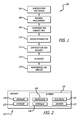
FIG. 1 is a flow diagram of aircraft production and service methodology; -
FIG. 2 is a block diagram of an aircraft; -
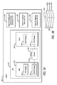
FIG. 3A is a block diagram of a system, according to an aspect of the present disclosure; -
FIG. 3B is a perspective view of an exemplary workpiece that may be processed by the disclosed system, according to an aspect of the present disclosure; -
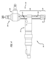
FIG. 4 is a schematic view of the system ofFIG. 3A , according to an aspect of the present disclosure; -
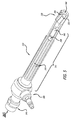
FIG. 5 is perspective view of the tool shown inFIG. 4 , according to an aspect of the present disclosure; -
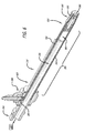
FIG. 6 is a perspective sectional view of the tool ofFIG. 3A , according to an aspect of the present disclosure; -
FIG. 7 is perspective detail view of the reamer-type cutter and a portion of the tool ofFIGS. 5 , according to an aspect of the present disclosure; -
FIG. 8 is a perspective view of one example of a body of the tool ofFIG. 3A , according to an aspect of the present disclosure; -
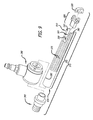
FIG. 9 is an exploded perspective view of an example of the tool ofFIG. 3A , according to an aspect of the present disclosure; -
FIG. 10 is an exploded perspective view of another example of the tool ofFIG. 3A , according to an aspect of the present disclosure; -
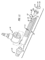
FIG. 11 is an exploded perspective view of yet another example of the tool ofFIG. 3A , according to an aspect of the present disclosure; -
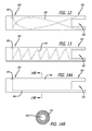
FIG. 12 is a schematic side elevation view of an example of the tool ofFIG. 3A having a curved passage, according to an aspect of the present disclosure; -
FIG. 13 is a schematic side elevation view of another example of the tool ofFIG. 3A having a spiral passage, according to an aspect of the present disclosure; -
FIG. 14A is a schematic side elevation view of yet another example of the tool ofFIG. 3A having an annular passage, according to an aspect of the present disclosure; and -
FIG. 14B is a schematic cross-sectional view of the tool ofFIG. 14A , according to an aspect of the present disclosure. - Examples of the disclosure may be described in the context of an aircraft manufacturing and
service method 100 as shown inFIG. 1 and anaircraft 102 as shown inFIG. 2 . During pre-production,exemplary method 100 may include specification anddesign 104 of theaircraft 102 andmaterial procurement 106. During production, component andsubassembly manufacturing 108 andsystem integration 110 of the aircraft take place. Thereafter, theaircraft 102 may go through certification anddelivery 112 to be placed inservice 114. While in service by a customer, theaircraft 102 is scheduled for routine maintenance and service 116 (which may also include modification, reconfiguration, refurbishment, and so on). - Each of the processes of the
illustrative method 100 may be performed or carried out by a system integrator, a third party, and/or an operator (e.g., a customer). For the purposes of this description, a system integrator may include, without limitation, any number of aircraft manufacturers and major-system subcontractors; a third party may include, without limitation, any number of vendors, subcontractors, and suppliers; and an operator may be an airline, leasing company, military entity, service organization, and so on. - As shown in
FIG. 2 , theaircraft 102 produced by theillustrative method 100 may include anairframe 118 with a plurality of high-level systems 120 and an interior 122. Examples of high-level systems 120 include one or more of apropulsion system 124, anelectrical system 126, ahydraulic system 128, and anenvironmental system 130. Any number of other systems may be included. Although an aerospace example is shown, the principles of the invention may be applied to other industries, such as the automotive industry. - Apparatus and methods shown or described herein may be employed during any one or more of the stages of the manufacturing and
service method 100. For example, components or subassemblies corresponding to component andsubassembly manufacturing 108 may be fabricated or manufactured in a manner similar to components or subassemblies produced while theaircraft 102 is in service. Also, one or more aspects of the apparatus, method, or combination thereof may be utilized during the production states 108 and 110, for example, by substantially expediting assembly of or reducing the cost of anaircraft 102. Similarly, one or more of apparatus or method realizations, or a combination thereof, may be utilized, for example and without limitation, while theaircraft 102 is in service, e.g., maintenance andservice 116. - As illustrated in
FIGS. 3A and 3B , one example of the disclosure relates to asystem 300 for processing alocation 302 of aworkpiece 301. The system includes atool 310, including afirst passage 330, configured to supply vacuum to thelocation 302, and asecond passage 340, formed along thefirst passage 330, where thesecond passage 340 is configured to supply fluid to thelocation 302. The system also includesmeans 370 for rotating and selectively axially vibrating thetool 310, means 380 for supplying fluid to thetool 310, and means 390 for supplying vacuum to thetool 310. - Referring to
FIG. 3B , theworkpiece 301 may include any number of different materials including, but not limited to, metal, carbon fiber reinforced plastics (CFRP), and/or other materials. Metallic components of theworkpiece 301 may include, but are not limited to, aluminum (Al), titanium (Ti), and stainless steel. In one example, theworkpiece 301 may be manufactured to include any number of layers 303 of different materials stacked together. For example, layers 303a and 303c may be made of CFRP, and alayer 303b may be made of metal. - Referring once again to
FIG. 3A , different types of drills may be employed as themeans 370 for rotating and selectively axially vibrating thetool 310. Such drills may include, but are not limited to, micro-peck drills. Commercially available micro-peck drills that may be employed include, but are not limited to, Set-Tec ST1200, manufactured by Desoutter, Rock Hill, South Carolina; Set-Tec ST2200, manufactured by Desoutter, Rock Hill, South Carolina; and/or PFD1100, manufactured by Atlas Copco Tools Inc., Auburn Hills, Michigan. - Moreover, different types of fluid sources may be employed as the
means 380 for supplying fluid to thetool 310. For example, a fluid pump, such as a Typhoon pump, manufactured by Unist Inc., Grand Rapids, Michigan, may be utilized as themeans 380. Additionally, different types of vacuum sources may be employed as themeans 390 for supplying vacuum to thetool 310. In one example, a Central Vacuum System vacuum source, manufactured by Spencer, Windsor, Connecticut, may be used as themeans 390. - In
FIG. 3A , lines connecting various elements and/or components of thesystem 300 may represent mechanical, electrical, fluid, optical, electromagnetic, and other couplings and/or combinations thereof. Couplings other than those depicted inFIG. 3A may also exist. Dashed lines connecting the various elements and/or components of thesystem 300 may represent couplings similar in function and purpose to those represented by solid lines; however, couplings represented by the dashed lines relate to alternative or optional aspects of the disclosure. Likewise, elements and/or components of thesystem 300 represented in dashed lines represent alternative or optional aspects of the disclosure. - Referring, e.g., to
FIGS. 3A and 3B , one example of the disclosure relates to thetool 310 for processing thelocation 302 of theworkpiece 301. The tool includes thefirst passage 330, configured to supply vacuum to thelocation 302, and thesecond passage 340, configured to supply fluid to thelocation 302. Thesecond passage 340 is formed along thefirst passage 330, as shown, for example, inFIG. 6 . According to one aspect of the disclosure, thefirst passage 330 has a first diameter, thesecond passage 340 has a second diameter, and a ratio of the second diameter to the first diameter is between about 0.03 and about 0.09. The second diameter of thesecond passage 340 is much smaller than the first diameter of thefirst passage 330 to ensure that thesecond passage 340 provides a controlled amount of fluid, sufficient to lubricate and cool thetool 310 and thelocation 302 of theworkpiece 301 without supplying an excessive amount of fluid that would be difficult to remove. In one aspect, thefirst passage 330 may have a diameter of about 0.340 inches (8.6 mm). In another alternative, the diameter of thefirst passage 330 may be about 0.800 inches (20.3 mm). Those skilled in the art will appreciate that thefirst passage 330 and thesecond passage 340 may have a variety of different sizes. - In one aspect, referring to
FIGS. 3A-7 , thetool 310 also includes acutter 320. In one aspect, thecutter 320 is removable from thetool 310. Thecutter 320 may include athird passage 350 in communication with thesecond passage 340. In one aspect, thecutter 320 also includes afourth passage 360 in communication with thefirst passage 330. - Different types of cutting tips may be employed as the
cutter 320. For example,FIGS. 4-7 illustrate thecutter 320 as a reamer. Those skilled in the art will appreciate that a variety of reamers may be utilized. Referring toFIGS. 9-11 , for example, a drill tip may also be employed as thecutter 320. Those skilled in the art will similarly appreciate that different types of drill tips may be utilized. - Turning, for instance, to
FIGS. 3A ,6 , and8 , in one aspect, thetool 310 also includes abody 355, including aproximal portion 820 and adistal portion 810 opposite theproximal portion 820. Thefirst passage 330 and thesecond passage 340 are formed within thebody 355. Thefirst passage 330 and thesecond passage 340 extend between theproximal portion 820 and thedistal portion 810. Thebody 355 includes at least oneinlet 365 in thedistal portion 810. The inlet(s) 365 is in communication with thefirst passage 330. The inlet(s) 365, as is shown, is axially oriented in thebody 355. Alternatively, the inlet(s) 365 may be laterally oriented in thebody 355. Thebody 355 includes at least oneentry port 385 for communicating fluid therethrough from themeans 380. The entry port(s) 385 is in theproximal portion 820. The entry port(s) 385 is in communication with thesecond passage 340. As is shown, the entry port(s) 385 is generally circular in shape, but those skilled in the art will appreciate that the port may have a different shape, as necessary. - Referring, for example, to
FIGS. 3A ,9 ,10 , and11 , thetool 310 also may include anadapter 395 coupled to theproximal portion 820 of thebody 355. In one aspect, referring toFIG. 9 , thetool 310 may include aninterface 900 coupled to thedistal portion 810 of thebody 355. Thetool 310 may also include acutter 320 removably coupled to theinterface 900. Thecutter 320 may be coupled to theinterface 900 by various different means including, but not limited to, screws and fasteners (not shown). - In one aspect, referring to
FIG. 10 , theinterface 900 may include achannel 920 that is in communication with thesecond passage 340 of thebody 355. In one aspect, referring toFIG. 11 , the cutter may include athird passage 350 that is in communication with thechannel 920 in theinterface 900. Thechannel 920 is also in communication with thesecond passage 340 of thebody 355 and thethird passage 350 is in communication with thesecond passage 340 via thechannel 920 of theinterface 900. - In one aspect, referring to
FIG. 6 , thesecond passage 340 is straight. Alternatively, thesecond passage 340 may be curved (refer toFIG. 12 ). In yet another aspect, thesecond passage 340 may be generally spiral, such as a helix (refer toFIG. 13 ). Also, at least a portion of thesecond passage 340 may be annular (refer toFIGS. 14A and 14B ). - Referring to
FIGS. 3B ,8 ,9 ,10 , and11 , one example of the present disclosure relates to a method for manufacturing thetool 310 for processing alocation 302 of theworkpiece 301. The method includes extruding thebody 355, including theproximal portion 820 and thedistal portion 810 opposite theproximal portion 820; extruding thefirst passage 330 within thebody 355; and extruding thesecond passage 340 within thebody 355, where thesecond passage 340 is formed along thefirst passage 330. In one aspect, the method also includes brazing theadaptor 395 to theproximal portion 820 of thebody 355. In one aspect, the method also includes brazing theinterface 900, to thedistal portion 810 of thebody 355. As is shown, thebody 355 is extruded to be generally cylindrical in shape. In addition, the method may include machining thebody 355 to have at least oneflute 375. - One example of the present disclosure relates to a method of processing the
location 302 of theworkpiece 301. The method includes advancing thetool 310 into theworkpiece 301 while rotating and selectively axially vibrating thetool 310; selectively supplying a fluid through thetool 310 to thelocation 302; and evacuating, through thetool 310, processing debris and the fluid from thelocation 302. Evacuating the processing debris includes supplying a vacuum through thetool 310 to thelocation 302. The fluid is supplied through thetool 310 to thelocation 302 under a pressure. In one aspect, the pressure may be between approximately 30 pounds per square inch (PSI) and approximately 120 PSI. - In one aspect, the method also includes advancing the
tool 310 into a layer of theworkpiece 301 made of a non-metallic material. In one aspect, advancing thetool 310 into the non-metallic layer also includes avoiding supplying the fluid to thelocation 302. In one aspect, advancing thetool 310 into the non-metallic layer also includes avoiding axially vibrating thetool 310. - One example of the present disclosure relates to a method of processing the
location 302 of theworkpiece 301, where theworkpiece 301 includes the layer R and the layer Ω. The method includes advancing thetool 310 into the layer R at a first feed rate while rotating thetool 310 at a first rotational speed and selectively axially vibrating thetool 310 at a first frequency and a first amplitude; advancing thetool 310 into the layer Ω at a second feed rate while rotating thetool 310 at a second rotational speed and selectively axially vibrating thetool 310 at a second frequency and a second amplitude; selectively supplying a fluid through thetool 310 to thelocation 302; and evacuating, through thetool 310, processing debris and the fluid from thelocation 302. - In one aspect, the layer R is made of a non-metallic material and the layer Ω is made of a metallic material. With the layer R made of a non-metallic material and the layer Ω made of a metallic material, the first rotational speed may be greater than the second rotational speed and advancing the
tool 310 into the layer R may include avoiding supplying the fluid to thelocation 302. In one aspect, advancing thetool 310 into the non-metallic layer R also includes avoiding axially vibrating the tool. - In one aspect, the first rotational speed of the
tool 310, as it is advanced into the layer R, is equal to the second rotational speed of the tool, as it is advanced into the layer Ω. Alternatively, the first rotational speed may be greater than the second rotational speed. In another aspect, the first rotational speed may be less than the second rotational speed. For example, a maximum rotational speed may be approximately 1000 revolutions per minute (RPM). - In one aspect, the first frequency of vibration of the
tool 310, as it is advanced into the layer R, is equal to the second frequency of vibration of the tool, as it is advanced into the layer Ω. Alternatively, the first frequency may be greater than the second frequency. In another aspect, the first frequency may be less than the second frequency. As an example, thetool 310 may have a frequency of vibration of about three to seven cycles per revolution of thetool 310. - In one aspect, the first feed rate of the
tool 310, as it is advanced into the layer R, is equal to the second feed rate of the tool, as it is advanced into the layer Ω. Alternatively, the first feed rate may be greater than the second feed rate. In another aspect, the first feed rate may be less than the second feed rate. For example, a maximum feed rate may be approximately 0.006 inches per revolution (approximately 0.1524 millimeters per revolution). - In one aspect, the first amplitude of vibration of the
tool 310, as it is advanced into the layer R, is equal to the second amplitude of vibration of the tool, as it is advanced into the layer Ω. Alternatively, the first amplitude may be greater than the second amplitude. In another aspect, the first amplitude may be less than the second amplitude. As an example, thetool 310 may be axially vibrated at an amplitude between approximately 0.10 millimeters (mm) and approximately 0.30 mm. - Different examples and aspects of the apparatus and methods are disclosed herein that include a variety of components, features, and functionality. It should be understood that the various examples and aspects of the apparatus and methods disclosed herein may include any of the components, features, and functionality of any of the other examples and aspects of the apparatus and methods disclosed herein in any combination, and all of such possibilities are intended to be within the spirit and scope of the present disclosure.
- Many modifications and other examples of the disclosure set forth herein will come to mind to one skilled in the art to which the disclosure pertains having the benefit of the teachings presented in the foregoing descriptions and the associated drawings.
- Therefore, it is to be understood that the disclosure is not to be limited to the specific embodiments disclosed and that modifications and other embodiments are intended to be included within the scope of the appended claims. Moreover, although the foregoing descriptions and the associated drawings describe example embodiments in the context of certain illustrative combinations of elements and/or functions, it should be appreciated that different combinations of elements and/or functions may be provided by alternative implementations without departing from the scope of the appended claims.
Claims (15)
- A tool (310) for processing a location (302) of a workpiece (301), the tool (310) comprising:a first passage (330) configured to supply a vacuum to the location (302); anda second passage (340) configured to supply a fluid to the location (302), wherein the second passage (340) is formed along the first passage (330).
- The tool (310) of claim 1, wherein the first passage (330) has a first diameter, the second passage (340) has a second diameter, and a ratio of the second diameter to the first diameter is between about 0.03 and about 0.09.
- The tool (310) of any of claims 1-2, further comprising a cutter (320).
- The tool (310) of claim 3, wherein the cutter (320) comprises a third passage (350) in communication with the second passage (340).
- The tool (310) of claim 4, wherein the cutter (320) comprises a fourth passage (360) in communication with the first passage (330).
- The tool (310) of any of claims 1-5, further comprising a body (355) comprising a proximal portion (820) and a distal portion (810) opposite the proximal portion (820).
- The tool (310) of claim 6, wherein the body (355) comprises at least one inlet (365) in the distal portion (810), wherein the at least one inlet (365) is in communication with the first passage (330).
- The tool (310) of any of claims 6-7, wherein the body (355) comprises at least one entry port (385).
- The tool (310) of claim 8, wherein the at least one entry port (385) is in the proximal portion (820), wherein the at least one entry port (385) is in communication with the second passage (340).
- The tool (310) of any of claims 6-9, further comprising an adapter (395) coupled to the proximal portion (820) of the body (355).
- A method of processing a location (302) of a workpiece (301), the method comprising:advancing a tool (310) into the workpiece (301) while rotating and selectively axially vibrating the tool (310);selectively supplying a fluid through the tool (310) to the location (302); andevacuating, through the tool (310), processing debris and the fluid from the location (302).
- The method of claim 11, wherein evacuating the processing debris includes supplying a vacuum through the tool (310) to the location (302).
- The method of any of claims 11-12, further including advancing the tool (310) into a layer of the workpiece (301), wherein the layer is made of a non-metallic material.
- The method of claim 13, further comprising avoiding supplying the fluid to the location (302).
- The method of any of claims 13-14, further comprising avoiding axially vibrating the tool (310).
Applications Claiming Priority (1)
| Application Number | Priority Date | Filing Date | Title |
|---|---|---|---|
| US13/970,305 US9555480B2 (en) | 2013-08-19 | 2013-08-19 | Fluid-fed vacuum cutters |
Publications (2)
| Publication Number | Publication Date |
|---|---|
| EP2839924A1 true EP2839924A1 (en) | 2015-02-25 |
| EP2839924B1 EP2839924B1 (en) | 2016-04-27 |
Family
ID=51421814
Family Applications (1)
| Application Number | Title | Priority Date | Filing Date |
|---|---|---|---|
| EP14180797.4A Active EP2839924B1 (en) | 2013-08-19 | 2014-08-13 | Fluid-fed vacuum cutters |
Country Status (6)
| Country | Link |
|---|---|
| US (1) | US9555480B2 (en) |
| EP (1) | EP2839924B1 (en) |
| JP (2) | JP6441607B2 (en) |
| KR (1) | KR102180209B1 (en) |
| CN (1) | CN104416415B (en) |
| CA (2) | CA2856425C (en) |
Cited By (3)
| Publication number | Priority date | Publication date | Assignee | Title |
|---|---|---|---|---|
| WO2019086169A1 (en) * | 2017-10-30 | 2019-05-09 | Robert Bosch Gmbh | Drilling tool |
| WO2019086171A1 (en) * | 2017-10-30 | 2019-05-09 | Robert Bosch Gmbh | Suction adapter |
| GB2623578A (en) * | 2022-10-21 | 2024-04-24 | Univ Sheffield | A machining tool for creating openings in a multi-layered material |
Families Citing this family (8)
| Publication number | Priority date | Publication date | Assignee | Title |
|---|---|---|---|---|
| US9555480B2 (en) | 2013-08-19 | 2017-01-31 | The Boeing Company | Fluid-fed vacuum cutters |
| DE102013114792A1 (en) * | 2013-09-13 | 2015-03-19 | Jakob Lach Gmbh & Co. Kg | Cutting tool, in particular drilling and milling tool |
| FR3047836B1 (en) * | 2016-02-12 | 2019-05-24 | Areva Np | DEVICE AND METHOD FOR WATER REPAIRING A HOLE OF A NUCLEAR REACTOR PART |
| US9937599B1 (en) * | 2016-10-07 | 2018-04-10 | The Boeing Company | Debris collection for a milling process |
| DE102016120595A1 (en) * | 2016-10-27 | 2018-05-03 | Komet Group Gmbh | cutting tool |
| US10486253B2 (en) * | 2017-01-04 | 2019-11-26 | Kennametal Inc. | Metal-cutting tool, in particular a reaming tool and method of making the same |
| US20230082304A1 (en) * | 2020-02-12 | 2023-03-16 | Milwaukee Electric Tool Corporation | Accessory for an oscillating power tool |
| US11938551B2 (en) * | 2020-06-18 | 2024-03-26 | Ford Global Technologies, Llc | 3D printed gear cutting tools with capillaries for minimum quantity lubrication, gas or liquid |
Citations (3)
| Publication number | Priority date | Publication date | Assignee | Title |
|---|---|---|---|---|
| EP1506070A1 (en) * | 2002-05-17 | 2005-02-16 | Kennamental Inc. | Milling cutter |
| EP1627703A1 (en) * | 2004-08-17 | 2006-02-22 | Messier-Dowty S.A. | Deep-drilling head and process of deep-drilling for the drilling of a workpiece |
| EP2559508A1 (en) * | 2010-04-12 | 2013-02-20 | UHT Corporation | Boring device |
Family Cites Families (29)
| Publication number | Priority date | Publication date | Assignee | Title |
|---|---|---|---|---|
| US800894A (en) * | 1904-10-19 | 1905-10-03 | Stephen W Baldwin | Drilling apparatus. |
| US3032129A (en) | 1959-05-01 | 1962-05-01 | J H Fletcher & Co | Dust collecting drill steel and bit |
| US3144912A (en) | 1960-11-21 | 1964-08-18 | Black & Decker Mfg Co | Masonry drilling apparatus |
| US3619671A (en) * | 1969-12-29 | 1971-11-09 | Branson Instr | Transducer for ultrasonic machine tool |
| US3893355A (en) * | 1973-12-21 | 1975-07-08 | Giddings & Lewis | Coolant supply system for cutting tools in a machine tool |
| JPS5727606A (en) * | 1980-07-25 | 1982-02-15 | Nippon Yakin:Kk | Deep hole cutting device |
| SU1184617A1 (en) * | 1983-11-22 | 1985-10-15 | Предприятие П/Я А-7555 | Apparatus for ultrasound drilling of materials |
| JPS60259303A (en) * | 1985-06-03 | 1985-12-21 | Nippon Yakin:Kk | Deep-hole cutting apparatus |
| EP0212195B1 (en) * | 1985-07-16 | 1990-03-28 | Starrfräsmaschinen AG | Dust decrease and chip transferring and apparatus on a machine tool work station |
| US4688970A (en) * | 1985-08-09 | 1987-08-25 | Dresser Industries, Inc. | Power drill and automatic control system therefore |
| DE3817799C1 (en) * | 1988-05-26 | 1989-11-30 | A. Ott Gmbh, 8960 Kempten, De | Rotary transmission leadthrough for fluids, in particular for machine-tool spindles |
| EP0430536B1 (en) * | 1989-11-25 | 1994-03-09 | Omi Kogyo Co., Ltd. | Drill |
| JPH06259303A (en) * | 1993-03-09 | 1994-09-16 | Hitachi Ltd | Decentralized file system |
| DE19538762C1 (en) * | 1995-10-18 | 1997-04-10 | Hueller Hille Gmbh | Process for cooling and lubricating a cutting, rotating tool with a geometrically defined cutting edge and / or the workpiece in the machining area u. Machining spindle to carry out the process |
| JP3924365B2 (en) | 1997-11-28 | 2007-06-06 | ユニカ株式会社 | Dust absorption adapter |
| JP2002036056A (en) * | 2000-07-21 | 2002-02-05 | Honda Motor Co Ltd | Cutting equipment |
| JP2002283176A (en) * | 2001-03-28 | 2002-10-03 | Honda Motor Co Ltd | Suction type cutting machine |
| SE526387C2 (en) * | 2003-05-08 | 2005-09-06 | Seco Tools Ab | Drill bit for chip removal machining with all parts made of a material and with enclosed coil channel |
| CN100479957C (en) * | 2004-07-02 | 2009-04-22 | 索尔有限公司 | Tool with oscillating head |
| JP4596366B2 (en) * | 2005-07-08 | 2010-12-08 | 日立工機株式会社 | Vibration drill |
| US7563060B2 (en) | 2005-10-13 | 2009-07-21 | The Boeing Company | Vacuum drilling system |
| CN100404520C (en) * | 2006-08-15 | 2008-07-23 | 北京诺瑞医药技术有限公司 | Method of extracting and separating 10-deacetyl bakadin III from European yew branches and leaves |
| JP3132125U (en) * | 2007-03-16 | 2007-05-31 | 徳信發企業有限公司 | Tungsten steel cutting blade structure |
| JP2009012084A (en) * | 2007-06-29 | 2009-01-22 | Okuma Corp | Cutting method |
| JP5622463B2 (en) * | 2010-07-09 | 2014-11-12 | 株式会社スギノマシン | Drilling control method and drilling apparatus |
| JP5802893B2 (en) * | 2011-05-18 | 2015-11-04 | Uht株式会社 | Drill and drilling device using the same |
| JP5664506B2 (en) * | 2011-09-09 | 2015-02-04 | 三菱マテリアル株式会社 | Replaceable head cutting tool |
| SG11201509529VA (en) * | 2013-05-28 | 2015-12-30 | Allied Machine & Eng Corp | Vacuum drilling system and methods |
| US9555480B2 (en) | 2013-08-19 | 2017-01-31 | The Boeing Company | Fluid-fed vacuum cutters |
-
2013
- 2013-08-19 US US13/970,305 patent/US9555480B2/en active Active
-
2014
- 2014-07-10 CA CA2856425A patent/CA2856425C/en active Active
- 2014-07-10 CA CA2991830A patent/CA2991830C/en active Active
- 2014-07-11 KR KR1020140087564A patent/KR102180209B1/en active Active
- 2014-08-05 JP JP2014159454A patent/JP6441607B2/en active Active
- 2014-08-13 EP EP14180797.4A patent/EP2839924B1/en active Active
- 2014-08-19 CN CN201410409175.8A patent/CN104416415B/en active Active
-
2018
- 2018-11-22 JP JP2018218940A patent/JP6713033B2/en active Active
Patent Citations (3)
| Publication number | Priority date | Publication date | Assignee | Title |
|---|---|---|---|---|
| EP1506070A1 (en) * | 2002-05-17 | 2005-02-16 | Kennamental Inc. | Milling cutter |
| EP1627703A1 (en) * | 2004-08-17 | 2006-02-22 | Messier-Dowty S.A. | Deep-drilling head and process of deep-drilling for the drilling of a workpiece |
| EP2559508A1 (en) * | 2010-04-12 | 2013-02-20 | UHT Corporation | Boring device |
Cited By (5)
| Publication number | Priority date | Publication date | Assignee | Title |
|---|---|---|---|---|
| WO2019086169A1 (en) * | 2017-10-30 | 2019-05-09 | Robert Bosch Gmbh | Drilling tool |
| WO2019086171A1 (en) * | 2017-10-30 | 2019-05-09 | Robert Bosch Gmbh | Suction adapter |
| US11660717B2 (en) | 2017-10-30 | 2023-05-30 | Robert Bosch Gmbh | Suction adapter |
| GB2623578A (en) * | 2022-10-21 | 2024-04-24 | Univ Sheffield | A machining tool for creating openings in a multi-layered material |
| GB2623578B (en) * | 2022-10-21 | 2025-02-12 | Univ Sheffield | A machining tool for creating openings in a multi-layered material |
Also Published As
| Publication number | Publication date |
|---|---|
| JP2019055479A (en) | 2019-04-11 |
| KR20150020989A (en) | 2015-02-27 |
| CA2856425A1 (en) | 2015-02-19 |
| US20150050093A1 (en) | 2015-02-19 |
| CN104416415B (en) | 2019-05-07 |
| CN104416415A (en) | 2015-03-18 |
| JP6441607B2 (en) | 2018-12-19 |
| US9555480B2 (en) | 2017-01-31 |
| JP6713033B2 (en) | 2020-06-24 |
| CA2991830C (en) | 2019-04-16 |
| EP2839924B1 (en) | 2016-04-27 |
| CA2856425C (en) | 2018-02-27 |
| CA2991830A1 (en) | 2015-02-19 |
| KR102180209B1 (en) | 2020-11-19 |
| JP2015037830A (en) | 2015-02-26 |
Similar Documents
| Publication | Publication Date | Title |
|---|---|---|
| CA2991830C (en) | Fluid-fed vacuum cutters | |
| Geng et al. | Rotary ultrasonic elliptical machining for side milling of CFRP: Tool performance and surface integrity | |
| JP5135614B2 (en) | Drill for composite material and machining method and machining apparatus using the same | |
| CN101600529B (en) | Cutter for drilling and reaming | |
| CN105378211B (en) | Vacuum drilling system and method | |
| JP5729554B2 (en) | Method for processing fiber reinforced composite material and tool thereof | |
| Liang et al. | Feasibility of ultrasonic vibration assisted grinding for carbon fiber reinforced polymer with monolayer brazed grinding tools | |
| Hrechuk et al. | Experimental investigations into tool wear of drilling CFRP | |
| US10442015B2 (en) | Cutting tool | |
| JP2010517799A5 (en) | ||
| AT518794B1 (en) | drilling | |
| US20120298214A1 (en) | Coolant adapter | |
| Dahnel et al. | Analysis of tool wear and hole quality during ultrasonic assisted drilling (UAD) of carbon fibre composite (CFC)/titanium alloy (Ti6Al4V) stacks | |
| US9937599B1 (en) | Debris collection for a milling process | |
| US9221141B1 (en) | Tuned mass tool holder | |
| CN105328215A (en) | Dedicated hole boring cutter and method for machining assembling holes in engine connecting rod | |
| CN204603398U (en) | Edge diamond blade socket drill | |
| Konneh et al. | Surface roughness study of milled carbon fiber Reinforced polymer (CFRP) composite using 4 mm 2-flute titanium aluminum nitride (TiAlN) coated carbide end Mills | |
| JP2021008000A (en) | End mill and drilling method | |
| Urrestia et al. | Spindle and cutting tools for internal suction of chip and dust in CFRP trimming | |
| Wei et al. | Investigation on Processing Technology in Machining CFRP Large Size Hole | |
| CN103338886A (en) | Drilling tool and method for producing drill holes | |
| CN108673312A (en) | A kind of machined piece grinding attachment |
Legal Events
| Date | Code | Title | Description |
|---|---|---|---|
| PUAI | Public reference made under article 153(3) epc to a published international application that has entered the european phase |
Free format text: ORIGINAL CODE: 0009012 |
|
| 17P | Request for examination filed |
Effective date: 20140813 |
|
| AK | Designated contracting states |
Kind code of ref document: A1 Designated state(s): AL AT BE BG CH CY CZ DE DK EE ES FI FR GB GR HR HU IE IS IT LI LT LU LV MC MK MT NL NO PL PT RO RS SE SI SK SM TR |
|
| AX | Request for extension of the european patent |
Extension state: BA ME |
|
| GRAP | Despatch of communication of intention to grant a patent |
Free format text: ORIGINAL CODE: EPIDOSNIGR1 |
|
| INTG | Intention to grant announced |
Effective date: 20151116 |
|
| RIN1 | Information on inventor provided before grant (corrected) |
Inventor name: KESTERSON, MATTHEW GREGORY Inventor name: DELAND, JAMES ALBERT |
|
| GRAS | Grant fee paid |
Free format text: ORIGINAL CODE: EPIDOSNIGR3 |
|
| GRAA | (expected) grant |
Free format text: ORIGINAL CODE: 0009210 |
|
| AK | Designated contracting states |
Kind code of ref document: B1 Designated state(s): AL AT BE BG CH CY CZ DE DK EE ES FI FR GB GR HR HU IE IS IT LI LT LU LV MC MK MT NL NO PL PT RO RS SE SI SK SM TR |
|
| REG | Reference to a national code |
Ref country code: GB Ref legal event code: FG4D |
|
| REG | Reference to a national code |
Ref country code: CH Ref legal event code: EP |
|
| REG | Reference to a national code |
Ref country code: AT Ref legal event code: REF Ref document number: 794180 Country of ref document: AT Kind code of ref document: T Effective date: 20160515 |
|
| REG | Reference to a national code |
Ref country code: IE Ref legal event code: FG4D |
|
| REG | Reference to a national code |
Ref country code: DE Ref legal event code: R096 Ref document number: 602014001689 Country of ref document: DE |
|
| REG | Reference to a national code |
Ref country code: LT Ref legal event code: MG4D Ref country code: FR Ref legal event code: PLFP Year of fee payment: 3 |
|
| REG | Reference to a national code |
Ref country code: NL Ref legal event code: MP Effective date: 20160427 |
|
| REG | Reference to a national code |
Ref country code: AT Ref legal event code: MK05 Ref document number: 794180 Country of ref document: AT Kind code of ref document: T Effective date: 20160427 |
|
| PG25 | Lapsed in a contracting state [announced via postgrant information from national office to epo] |
Ref country code: NL Free format text: LAPSE BECAUSE OF FAILURE TO SUBMIT A TRANSLATION OF THE DESCRIPTION OR TO PAY THE FEE WITHIN THE PRESCRIBED TIME-LIMIT Effective date: 20160427 |
|
| PG25 | Lapsed in a contracting state [announced via postgrant information from national office to epo] |
Ref country code: NO Free format text: LAPSE BECAUSE OF FAILURE TO SUBMIT A TRANSLATION OF THE DESCRIPTION OR TO PAY THE FEE WITHIN THE PRESCRIBED TIME-LIMIT Effective date: 20160727 Ref country code: FI Free format text: LAPSE BECAUSE OF FAILURE TO SUBMIT A TRANSLATION OF THE DESCRIPTION OR TO PAY THE FEE WITHIN THE PRESCRIBED TIME-LIMIT Effective date: 20160427 Ref country code: LT Free format text: LAPSE BECAUSE OF FAILURE TO SUBMIT A TRANSLATION OF THE DESCRIPTION OR TO PAY THE FEE WITHIN THE PRESCRIBED TIME-LIMIT Effective date: 20160427 Ref country code: PL Free format text: LAPSE BECAUSE OF FAILURE TO SUBMIT A TRANSLATION OF THE DESCRIPTION OR TO PAY THE FEE WITHIN THE PRESCRIBED TIME-LIMIT Effective date: 20160427 |
|
| PG25 | Lapsed in a contracting state [announced via postgrant information from national office to epo] |
Ref country code: SE Free format text: LAPSE BECAUSE OF FAILURE TO SUBMIT A TRANSLATION OF THE DESCRIPTION OR TO PAY THE FEE WITHIN THE PRESCRIBED TIME-LIMIT Effective date: 20160427 Ref country code: LV Free format text: LAPSE BECAUSE OF FAILURE TO SUBMIT A TRANSLATION OF THE DESCRIPTION OR TO PAY THE FEE WITHIN THE PRESCRIBED TIME-LIMIT Effective date: 20160427 Ref country code: ES Free format text: LAPSE BECAUSE OF FAILURE TO SUBMIT A TRANSLATION OF THE DESCRIPTION OR TO PAY THE FEE WITHIN THE PRESCRIBED TIME-LIMIT Effective date: 20160427 Ref country code: HR Free format text: LAPSE BECAUSE OF FAILURE TO SUBMIT A TRANSLATION OF THE DESCRIPTION OR TO PAY THE FEE WITHIN THE PRESCRIBED TIME-LIMIT Effective date: 20160427 Ref country code: RS Free format text: LAPSE BECAUSE OF FAILURE TO SUBMIT A TRANSLATION OF THE DESCRIPTION OR TO PAY THE FEE WITHIN THE PRESCRIBED TIME-LIMIT Effective date: 20160427 Ref country code: PT Free format text: LAPSE BECAUSE OF FAILURE TO SUBMIT A TRANSLATION OF THE DESCRIPTION OR TO PAY THE FEE WITHIN THE PRESCRIBED TIME-LIMIT Effective date: 20160829 Ref country code: AT Free format text: LAPSE BECAUSE OF FAILURE TO SUBMIT A TRANSLATION OF THE DESCRIPTION OR TO PAY THE FEE WITHIN THE PRESCRIBED TIME-LIMIT Effective date: 20160427 Ref country code: GR Free format text: LAPSE BECAUSE OF FAILURE TO SUBMIT A TRANSLATION OF THE DESCRIPTION OR TO PAY THE FEE WITHIN THE PRESCRIBED TIME-LIMIT Effective date: 20160728 |
|
| PG25 | Lapsed in a contracting state [announced via postgrant information from national office to epo] |
Ref country code: BE Free format text: LAPSE BECAUSE OF FAILURE TO SUBMIT A TRANSLATION OF THE DESCRIPTION OR TO PAY THE FEE WITHIN THE PRESCRIBED TIME-LIMIT Effective date: 20160427 Ref country code: IT Free format text: LAPSE BECAUSE OF FAILURE TO SUBMIT A TRANSLATION OF THE DESCRIPTION OR TO PAY THE FEE WITHIN THE PRESCRIBED TIME-LIMIT Effective date: 20160427 |
|
| REG | Reference to a national code |
Ref country code: DE Ref legal event code: R097 Ref document number: 602014001689 Country of ref document: DE |
|
| PG25 | Lapsed in a contracting state [announced via postgrant information from national office to epo] |
Ref country code: DK Free format text: LAPSE BECAUSE OF FAILURE TO SUBMIT A TRANSLATION OF THE DESCRIPTION OR TO PAY THE FEE WITHIN THE PRESCRIBED TIME-LIMIT Effective date: 20160427 Ref country code: RO Free format text: LAPSE BECAUSE OF FAILURE TO SUBMIT A TRANSLATION OF THE DESCRIPTION OR TO PAY THE FEE WITHIN THE PRESCRIBED TIME-LIMIT Effective date: 20160427 Ref country code: EE Free format text: LAPSE BECAUSE OF FAILURE TO SUBMIT A TRANSLATION OF THE DESCRIPTION OR TO PAY THE FEE WITHIN THE PRESCRIBED TIME-LIMIT Effective date: 20160427 Ref country code: SK Free format text: LAPSE BECAUSE OF FAILURE TO SUBMIT A TRANSLATION OF THE DESCRIPTION OR TO PAY THE FEE WITHIN THE PRESCRIBED TIME-LIMIT Effective date: 20160427 Ref country code: CZ Free format text: LAPSE BECAUSE OF FAILURE TO SUBMIT A TRANSLATION OF THE DESCRIPTION OR TO PAY THE FEE WITHIN THE PRESCRIBED TIME-LIMIT Effective date: 20160427 |
|
| PG25 | Lapsed in a contracting state [announced via postgrant information from national office to epo] |
Ref country code: SM Free format text: LAPSE BECAUSE OF FAILURE TO SUBMIT A TRANSLATION OF THE DESCRIPTION OR TO PAY THE FEE WITHIN THE PRESCRIBED TIME-LIMIT Effective date: 20160427 |
|
| PLBE | No opposition filed within time limit |
Free format text: ORIGINAL CODE: 0009261 |
|
| STAA | Information on the status of an ep patent application or granted ep patent |
Free format text: STATUS: NO OPPOSITION FILED WITHIN TIME LIMIT |
|
| PG25 | Lapsed in a contracting state [announced via postgrant information from national office to epo] |
Ref country code: MC Free format text: LAPSE BECAUSE OF FAILURE TO SUBMIT A TRANSLATION OF THE DESCRIPTION OR TO PAY THE FEE WITHIN THE PRESCRIBED TIME-LIMIT Effective date: 20160427 |
|
| 26N | No opposition filed |
Effective date: 20170130 |
|
| PG25 | Lapsed in a contracting state [announced via postgrant information from national office to epo] |
Ref country code: SI Free format text: LAPSE BECAUSE OF FAILURE TO SUBMIT A TRANSLATION OF THE DESCRIPTION OR TO PAY THE FEE WITHIN THE PRESCRIBED TIME-LIMIT Effective date: 20160427 |
|
| REG | Reference to a national code |
Ref country code: IE Ref legal event code: MM4A |
|
| PG25 | Lapsed in a contracting state [announced via postgrant information from national office to epo] |
Ref country code: IE Free format text: LAPSE BECAUSE OF NON-PAYMENT OF DUE FEES Effective date: 20160813 |
|
| REG | Reference to a national code |
Ref country code: FR Ref legal event code: PLFP Year of fee payment: 4 |
|
| PG25 | Lapsed in a contracting state [announced via postgrant information from national office to epo] |
Ref country code: LU Free format text: LAPSE BECAUSE OF NON-PAYMENT OF DUE FEES Effective date: 20160813 |
|
| REG | Reference to a national code |
Ref country code: CH Ref legal event code: PL |
|
| PG25 | Lapsed in a contracting state [announced via postgrant information from national office to epo] |
Ref country code: LI Free format text: LAPSE BECAUSE OF NON-PAYMENT OF DUE FEES Effective date: 20170831 Ref country code: CH Free format text: LAPSE BECAUSE OF NON-PAYMENT OF DUE FEES Effective date: 20170831 |
|
| PG25 | Lapsed in a contracting state [announced via postgrant information from national office to epo] |
Ref country code: HU Free format text: LAPSE BECAUSE OF FAILURE TO SUBMIT A TRANSLATION OF THE DESCRIPTION OR TO PAY THE FEE WITHIN THE PRESCRIBED TIME-LIMIT; INVALID AB INITIO Effective date: 20140813 |
|
| PG25 | Lapsed in a contracting state [announced via postgrant information from national office to epo] |
Ref country code: MT Free format text: LAPSE BECAUSE OF NON-PAYMENT OF DUE FEES Effective date: 20160831 Ref country code: CY Free format text: LAPSE BECAUSE OF FAILURE TO SUBMIT A TRANSLATION OF THE DESCRIPTION OR TO PAY THE FEE WITHIN THE PRESCRIBED TIME-LIMIT Effective date: 20160427 Ref country code: MK Free format text: LAPSE BECAUSE OF FAILURE TO SUBMIT A TRANSLATION OF THE DESCRIPTION OR TO PAY THE FEE WITHIN THE PRESCRIBED TIME-LIMIT Effective date: 20160427 Ref country code: IS Free format text: LAPSE BECAUSE OF FAILURE TO SUBMIT A TRANSLATION OF THE DESCRIPTION OR TO PAY THE FEE WITHIN THE PRESCRIBED TIME-LIMIT Effective date: 20160427 |
|
| PG25 | Lapsed in a contracting state [announced via postgrant information from national office to epo] |
Ref country code: BG Free format text: LAPSE BECAUSE OF FAILURE TO SUBMIT A TRANSLATION OF THE DESCRIPTION OR TO PAY THE FEE WITHIN THE PRESCRIBED TIME-LIMIT Effective date: 20160427 |
|
| REG | Reference to a national code |
Ref country code: FR Ref legal event code: PLFP Year of fee payment: 5 |
|
| PG25 | Lapsed in a contracting state [announced via postgrant information from national office to epo] |
Ref country code: TR Free format text: LAPSE BECAUSE OF FAILURE TO SUBMIT A TRANSLATION OF THE DESCRIPTION OR TO PAY THE FEE WITHIN THE PRESCRIBED TIME-LIMIT Effective date: 20160427 Ref country code: AL Free format text: LAPSE BECAUSE OF FAILURE TO SUBMIT A TRANSLATION OF THE DESCRIPTION OR TO PAY THE FEE WITHIN THE PRESCRIBED TIME-LIMIT Effective date: 20160427 |
|
| P01 | Opt-out of the competence of the unified patent court (upc) registered |
Effective date: 20230516 |
|
| PGFP | Annual fee paid to national office [announced via postgrant information from national office to epo] |
Ref country code: DE Payment date: 20250827 Year of fee payment: 12 |
|
| PGFP | Annual fee paid to national office [announced via postgrant information from national office to epo] |
Ref country code: GB Payment date: 20250827 Year of fee payment: 12 |
|
| PGFP | Annual fee paid to national office [announced via postgrant information from national office to epo] |
Ref country code: FR Payment date: 20250825 Year of fee payment: 12 |