EP2839910A2 - Chuck locking device for spindles of machine tools - Google Patents
Chuck locking device for spindles of machine tools Download PDFInfo
- Publication number
- EP2839910A2 EP2839910A2 EP20140176936 EP14176936A EP2839910A2 EP 2839910 A2 EP2839910 A2 EP 2839910A2 EP 20140176936 EP20140176936 EP 20140176936 EP 14176936 A EP14176936 A EP 14176936A EP 2839910 A2 EP2839910 A2 EP 2839910A2
- Authority
- EP
- European Patent Office
- Prior art keywords
- locking device
- movable member
- under pressure
- axially fixed
- axially movable
- Prior art date
- Legal status (The legal status is an assumption and is not a legal conclusion. Google has not performed a legal analysis and makes no representation as to the accuracy of the status listed.)
- Granted
Links
Images





Classifications
-
- B—PERFORMING OPERATIONS; TRANSPORTING
- B23—MACHINE TOOLS; METAL-WORKING NOT OTHERWISE PROVIDED FOR
- B23B—TURNING; BORING
- B23B31/00—Chucks; Expansion mandrels; Adaptations thereof for remote control
- B23B31/02—Chucks
- B23B31/24—Chucks characterised by features relating primarily to remote control of the gripping means
- B23B31/30—Chucks characterised by features relating primarily to remote control of the gripping means using fluid-pressure means in the chuck
- B23B31/302—Hydraulic equipment, e.g. pistons, valves, rotary joints
-
- B—PERFORMING OPERATIONS; TRANSPORTING
- B23—MACHINE TOOLS; METAL-WORKING NOT OTHERWISE PROVIDED FOR
- B23B—TURNING; BORING
- B23B31/00—Chucks; Expansion mandrels; Adaptations thereof for remote control
- B23B31/02—Chucks
- B23B31/24—Chucks characterised by features relating primarily to remote control of the gripping means
- B23B31/26—Chucks characterised by features relating primarily to remote control of the gripping means using mechanical transmission through the working-spindle
-
- B—PERFORMING OPERATIONS; TRANSPORTING
- B23—MACHINE TOOLS; METAL-WORKING NOT OTHERWISE PROVIDED FOR
- B23Q—DETAILS, COMPONENTS, OR ACCESSORIES FOR MACHINE TOOLS, e.g. ARRANGEMENTS FOR COPYING OR CONTROLLING; MACHINE TOOLS IN GENERAL CHARACTERISED BY THE CONSTRUCTION OF PARTICULAR DETAILS OR COMPONENTS; COMBINATIONS OR ASSOCIATIONS OF METAL-WORKING MACHINES, NOT DIRECTED TO A PARTICULAR RESULT
- B23Q17/00—Arrangements for observing, indicating or measuring on machine tools
- B23Q17/002—Arrangements for observing, indicating or measuring on machine tools for indicating or measuring the holding action of work or tool holders
- B23Q17/005—Arrangements for observing, indicating or measuring on machine tools for indicating or measuring the holding action of work or tool holders by measuring a force, a pressure or a deformation
-
- B—PERFORMING OPERATIONS; TRANSPORTING
- B23—MACHINE TOOLS; METAL-WORKING NOT OTHERWISE PROVIDED FOR
- B23B—TURNING; BORING
- B23B2231/00—Details of chucks, toolholder shanks or tool shanks
- B23B2231/26—Detection of clamping
-
- B—PERFORMING OPERATIONS; TRANSPORTING
- B23—MACHINE TOOLS; METAL-WORKING NOT OTHERWISE PROVIDED FOR
- B23B—TURNING; BORING
- B23B2231/00—Details of chucks, toolholder shanks or tool shanks
- B23B2231/50—Devices to counteract clamping forces exerted within the spindle in order to release the tool or workpiece
-
- B—PERFORMING OPERATIONS; TRANSPORTING
- B23—MACHINE TOOLS; METAL-WORKING NOT OTHERWISE PROVIDED FOR
- B23B—TURNING; BORING
- B23B2260/00—Details of constructional elements
- B23B2260/128—Sensors
Definitions
- the present invention relates to a locking device for tools, in particular a device mountable on machine tools to lock and unlock a tool which is moved to perform a mechanical processing.
- Locking devices known for example from EP 780 192 A1 comprise an axially fixed component, inside of which there is an axially movable member adapted to lock and unlock the tool.
- Spring locking means bring the device to a locking position, while unlocking takes place by means of drive means with fluid under pressure.
- control system comprising a plurality of electrical switches fixed outside the axially fixed component to control the relative position of a shaped profile which is integral with the axially movable member and protrudes from the axially fixed component from the opposite side relative to the tool.
- a drawback of this known product lies in the fact that such control systems are mounted externally with respect to the locking device, thus being bulky. These tool holders are therefore not usable when the configuration of the machine tool requires, for constructional reasons, a locking device which is compact and has limited dimensions.
- Object of the present invention is therefore to provide a locking device free from the drawbacks described above. Said object is achieved with a locking device whose main features are specified in the first claim, while other features are specified in the remaining claims.
- the axially fixed component comprises an inlet and an outlet for a control fluid under pressure, which ducts can be connected to each other through annular chambers made on the axially movable member.
- the control fluid under pressure preferably air pumped by a compressor, reaches the outlet only with given relative positions between the axially movable member and the axially fixed component.
- control system since the control system to know the relative position of the axially movable member relative to the axially fixed component is incorporated within the locking device itself, it is possible to obtain a compact and not bulky product mountable on machines which, for structural reasons, have little space available on board. Moreover, with this arrangement, the flow detection means and the means for feeding the control fluid under pressure can also be mounted in a location far from the locking device.
- the locking device 10 is provided with an axially fixed component comprising a first axially fixed member 12, substantially cylindrical-shaped, which is arranged in a substantially coaxial manner in a second axially fixed member 13, also substantially cylindrical-shaped.
- Said axially fixed members 12, 13 are fastened to a head 11 arranged at one end thereof.
- At least one axially movable member 14, also substantially cylindrical-shaped, can slide in a substantially telescopic and/or coaxial manner between the axially fixed members 12, 13 to lock a tool (not shown in the figures).
- the first axially fixed member 12 also comprises a substantially annular-shaped flange 121 that is joined to the head 11 and/or to the second axially fixed member 13, acting as an abutment for the axially movable member 14.
- the flange 121 can be integral with the head 11 and/or with the second axially fixed member 13. In this way, the head 11 or the flange 121, the first axially fixed member 12, the second axially fixed member 13 and/or the axially movable member 14 define an actuation chamber 15.
- the head 11 may comprise a plurality of threaded blind holes 111 for mounting the locking device 10 on board of a machine tool.
- Resilient locking means urge the axially movable member 14 toward the axially fixed component 12, 13 along an axial direction A.
- an actuation fluid under pressure can be pumped into the actuation chamber 15 so as to translate the axially movable member 14 within the axially fixed component 12, 13 in the direction opposite to the direction A.
- the actuation fluid under pressure reaches the actuation chamber 15 via at least one duct 26 provided in the head 11 with a substantially radial arrangement and in the flange 121 with a substantially axial arrangement.
- the outer wall of the axially movable member 14 may comprise at least one groove provided with sealing means 22 at the interface with the internal wall of the second axially fixed member 13 for keeping the actuation fluid under pressure.
- the inner wall of the head 11 and/or of the outer wall of the flange 121 may include at least one groove provided with sealing members 23 at the interface of the duct 26 for keeping the actuation fluid under pressure.
- the sealing means 22 are annular seals with an X-shaped cross-section (X-ring) and the sealing members 23 are annular seals with a circular cross-section (O-ring).
- the actuation fluid under pressure may be pumped, as indicated by arrow F1, through actuating means 21 connected, for example through the duct 26, to means 20 for detecting the pressure of the fluid.
- the actuation fluid under pressure is a liquid, preferably oil
- the actuating means 21 comprise a pump and/or the means 20 for detecting the pressure of the actuating fluid comprise a pressure gauge.
- An actuator member 24, with a substantially cylindrical shape, axially movable with the axially movable member 14 is positioned in a substantially coaxial and/or telescopic manner inside the first axially fixed member 12.
- the actuator member 24 is connected via an axial duct 29 to a rotating mechanical seal 25 arranged in the axis of the first axially fixed member 12 at the head 11 and/or at the flange 121.
- a gap G Between the outer wall of the actuator member 24 and the inner wall of the first axially fixed member 12 there is a gap G, so that the actuator member 24 can be placed in rotation during the mechanical working.
- an axial bearing 28 Between the actuator member 24 and the axially movable member 14 there is an axial bearing 28.
- the locking device 10 may include a refrigeration system to provide a cooling fluid, as indicated by arrow F2, through the axial duct 29, the mechanical seal 25 and at least one duct 27 provided in the head 11.
- the locking device 10 comprises at least one inlet 16 and/or an outlet 17 for a control fluid under pressure.
- the ducts 16, 17 extend in a substantially radial manner inside of the head 11 or the flange 121 and in a substantially axial manner in the axially fixed component 12, 13, preferably in the first axially fixed member 12.
- the axial portions 16a, 17a of the ducts 16, 17 in the first axially fixed member 12 have one end plugged at the inner wall of the head 11.
- the axial portions 16a, 17a of the ducts 16, 17 are connected with the radial portions in the head 11 through intermediate portions 16b, 17b formed in the flange 121 with a substantially oblique orientation.
- the inlet 16 and the outlet 17 for the control fluid may be connected to each other, depending on the position of the axially movable member 14 with respect to the axially fixed component 12, 13, through at least one first chamber 18 and/or a second chamber 19, in particular annular grooves formed on the inner and/or outer walls of the axially movable member 14 at the interface respectively with the outer wall of the first axially fixed member 12 and/or with the inner wall of the second axially fixed member 13.
- the first chamber 18 is disposed in an innermost position, namely closer to the head 11, compared to the second chamber 19, which is in a distal position of the axially movable member 14.
- the second chamber 19 has an axial extension greater than the first chamber 18.
- the inlet 16 and the outlet 17 for the control fluid include terminal portions 16c, 17c which lead towards the interface with the axially movable member 14.
- the terminal portions 16c, 17c are arranged in a substantially radial manner in the first axially fixed member 12 and/or in the second axially fixed member 13 between the axial portions 16a, 17a of the ducts 16, 17 and, respectively, the outer wall of the first axially fixed member 12 and/or the inner wall of the second axially fixed member 13.
- the control fluid under pressure may be supplied, as indicated by arrow F3, via supply means 30 connected with the inlet 16, for example at the head 11.
- the control fluid under pressure may reach, when the inlet 16 and the outlet 17 are connected to each other, flow detection means connected with the outlet 17, for example at the head 11.
- the locking device 10 is shown in a retracted configuration, namely in a configuration in which the distance in the direction A between the head 11 and the axially movable member 14 is minimal.
- the actuating means 21 are not introducing actuation fluid under pressure into the actuation chamber 15, so that the axially movable member 14 is held in position by the resilient locking means.
- the inner wall of the head 11 and/or the outer wall of the flange 121 may include at least one groove provided with sealing members 32 at the interface with the inlet 16 and/or with the outlet 17 for keeping the control fluid under pressure.
- the sealing members 32 are annular seals with a circular cross-section (O-ring).
- the inner and/or external walls of the axially fixed members 12, 13 and/or of the axially movable member 14 may comprise one or more grooves provided with sealing means 31 at the interface with the wall adjacent for keeping the control fluid under pressure.
- the sealing means 31 are annular seals with a X-shaped cross-section (X-ring).
- the first chamber 18 and/or the second chamber 19 are arranged between two sealing means 31 arranged in corresponding grooves formed in the inner wall of the axially movable member 14.
- the flow detection means may comprise a first flow detection device 41, a second flow detection device 42 and/or a vent 43 arranged downstream of an electro-valve 40 with respect to a flow direction of the control under fluid pressure.
- the pressure detection means 20 of the actuating fluid under pressure return minimum values, namely when the pump 21 is turned off, the electro-valve 40 is in a first flow position.
- the outlet 17 of the locking device 10 is connected through the electro-valve 40 with the first flow detection device 41, while the second flow detection device 42 is put in flow communication with the vent 43, so as to eliminate residues of control fluid under pressure that may be present from the previous measurement, in order not to affect the subsequent measurement.
- both the pressure detection means 20 of the actuating fluid under pressure and the flow detection means 41, 42 of the control fluid under pressure return values lower than a preset threshold. These values are not necessarily equal to zero since, for example, if the ducts in which the fluids flow have long lengths, there will typically be a minimum residual pressure even when the actuating means 21 and/or the supply means 30 are not working.
- the combination of such measures may correspond to an automatic signal, for example to alert an operator that his intervention is required.
- the operator can program the machine tool to perform the mechanical working or verify any faults.
- control fluid under pressure is a gas, preferably air, and the supply means 30 consist of a compressor.
- the gas is pumped at a pressure comprised between 4 and 14 bar, preferably between 6 and 8 bar.
- the first flow detection device 41 and the second flow detection device 42 are pressure switches.
- the locking device 10 is in an extended configuration, namely a configuration in which the distance in the axial direction A between the axially movable member 14 and the head 11 is maximum.
- the locking device 10 in the extended configuration is adapted to interact with a tool through the actuator member 24, which is suitable to receive internally, or to release from its interior, a tool according to the axial direction A.
- the locking device 10 is brought from the retracted configuration to the extended configuration by providing an actuation fluid under pressure into the actuation chamber 15 so as to overcome the force of the spring locking means and to slide the axially movable member 14 between the axially fixed members 12, 13.
- the inlet 16 and outlet 17 are connected to each other through the first chamber 18 Consequently, the control fluid under pressure can reach, according to a direction indicated by the arrow F4, the flow detection means 41, 42.
- the outlet 17 is connected with the second flow detection device 42, while the first flow detection device 41 is connected with the vent 43.
- the combination of such measures may correspond for example to an automatic signal that drives a robot to insert a tool into the locking device 10.
- the locking device 10 is in an operative configuration, or a configuration in which the distance in the axial direction A between the head 11 and the axially movable member 14 has a value between the distance values corresponding to the retracted and extended configurations.
- the locking device 10 in the operating configuration has an internal tool (not shown in the figures) firmly and properly locked and positioned to start the machining.
- the locking device 10 is brought from the extended configuration to the operative configuration by the force of the locking means in the spring after the actuating fluid under pressure is no longer provided inside the actuation chamber 15.
- the inlet conduit 16 and the outlet conduit 17 are connected between them thanks to the second annular chamber 19 formed inside the member axially movable 14. Consequently, the control fluid under pressure can reach the outlet duct 17 and may be provided, according to the direction indicated by the arrow F4, to the means of detection of flow.
- the extension of the second annular chamber 19 in the direction of the axis A ie, the interval of positions in which this chamber leads the fluid control, identifies the field of work for the locking device 10.
- the pressure detection means of the actuating fluid under pressure return valuesbelow the preset threshold and the electro-valve 40, which is no longer activated, is again in the first flow position.
- the control fluid under pressure coming from the locking device 10, as indicated by the arrow F4 may reach the first flow detection means 41. Consequently, the pressure detection means 20 of the actuating fluid under pressure return values below a preset threshold, while the flow detection means of the control fluid under pressure return values exceeding a preset threshold.
- the combination of such measures may correspond for example to an automatic signal which actuates the machine tool to perform the mechanical working.
- the inlet 16 is connected with the outlet 17 through the second annular chamber 19 present on the axially movable member 14.
- the locking device 10 is in a non-operating configuration, namely a configuration in which the distance in the axial direction A between the head 11 and the axially movable member 14 has a value comprised between the values of distance corresponding to the operating and extended configurations.
- the non-operating configuration identifies a position in which the mechanical working cannot be started.
- the inlet 16 and the outlet 17 are not connected since they are, in particular, plugged by the inner wall of the axially movable member 14. Consequently, the control fluid under pressure cannot reach the outlet 17 and thus the flow detection means will not detect any flow of the control fluid under pressure.
- the actuating means 21 are not introducing actuating fluid under pressure into the actuation chamber 15 and the axially movable member 14 is held in position by the resilient locking means.
- both the pressure detection means of the actuating fluid under pressure and flow detection means of the control fluid under pressure return values below a preset threshold, in a manner similar to the retracted configuration.
- the combination of such measures may correspond for example to an automatic signal that alerts the operator that his intervention is required.
- the operator can intervene to return the machine tool to a condition for performing the mechanical working.
- a timer imposes a minimum waiting time before which the measures of the pressure detection means 20 of the actuating fluid under pressure and of the flow detection means of the control fluid under pressure are not read.
- the minimum waiting time can for example be comprised between 2 and 10 seconds, preferably between 4 and 8 seconds.
- a tool holder 10 such as that described is also applicable for static applications as, for example, to hold in position a mechanical piece that can be worked.
Landscapes
- Engineering & Computer Science (AREA)
- Mechanical Engineering (AREA)
- Gripping On Spindles (AREA)
- Manipulator (AREA)
- Automatic Tool Replacement In Machine Tools (AREA)
- Mounting, Exchange, And Manufacturing Of Dies (AREA)
Description
- The present invention relates to a locking device for tools, in particular a device mountable on machine tools to lock and unlock a tool which is moved to perform a mechanical processing.
- Locking devices known for example from
EP 780 192 A1 - Typically, on board of the machine tool there is a control system comprising a plurality of electrical switches fixed outside the axially fixed component to control the relative position of a shaped profile which is integral with the axially movable member and protrudes from the axially fixed component from the opposite side relative to the tool. Thus, not only the tool mounting/dismounting but also the mechanical working can be performed in an automated and safe manner.
- A drawback of this known product lies in the fact that such control systems are mounted externally with respect to the locking device, thus being bulky. These tool holders are therefore not usable when the configuration of the machine tool requires, for constructional reasons, a locking device which is compact and has limited dimensions.
- Object of the present invention is therefore to provide a locking device free from the drawbacks described above. Said object is achieved with a locking device whose main features are specified in the first claim, while other features are specified in the remaining claims.
- According to the present invention, the axially fixed component comprises an inlet and an outlet for a control fluid under pressure, which ducts can be connected to each other through annular chambers made on the axially movable member. In particular, the control fluid under pressure, preferably air pumped by a compressor, reaches the outlet only with given relative positions between the axially movable member and the axially fixed component.
- By connecting means for detecting the flow to the outlet and by providing means for detecting the pressure at the actuating means under pressure, it is possible to know the relative position between the axially movable member and the axially fixed component thanks to a comparison between the values measured by the flow detection means and by the pressure detection means.
- According to such solution, since the control system to know the relative position of the axially movable member relative to the axially fixed component is incorporated within the locking device itself, it is possible to obtain a compact and not bulky product mountable on machines which, for structural reasons, have little space available on board. Moreover, with this arrangement, the flow detection means and the means for feeding the control fluid under pressure can also be mounted in a location far from the locking device.
- Further advantages and features of the locking device according to the present invention will become evident to those skilled in the art from the following detailed and non-limiting description of an embodiment thereof with reference to the attached drawings in which:
-
Figure 1 shows a top view of the locking device according to the present invention; -
Figure 2 shows the section II-II ofFigure 1 , in which the locking device is in a retracted configuration; -
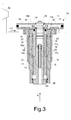
Figure 3 shows the section III-III ofFigure 1 ; -
Figure 4 shows an operating diagram of the locking device in a first position of the flow; -
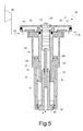
Figure 5 shows the locking device ofFigure 3 in an extended configuration; -
Figure 6 shows the diagram ofFigure 4 in a second position of the flow; -
Figure 7 shows the locking device ofFigure 3 in an operating configuration; -
Figure 8 shows the section VIII-VIII ofFigure 7 ; -
Figure 9 shows the locking device ofFigure 3 in a non-operating configuration; and -
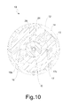
Figure 10 shows the section X-X ofFigure 9 . - Referring to
figures 1 to 4 , it is seen that thelocking device 10 according to the present invention is provided with an axially fixed component comprising a first axially fixedmember 12, substantially cylindrical-shaped, which is arranged in a substantially coaxial manner in a second axially fixedmember 13, also substantially cylindrical-shaped. Said axially fixedmembers head 11 arranged at one end thereof. At least one axiallymovable member 14, also substantially cylindrical-shaped, can slide in a substantially telescopic and/or coaxial manner between the axially fixedmembers member 12 also comprises a substantially annular-shaped flange 121 that is joined to thehead 11 and/or to the second axially fixedmember 13, acting as an abutment for the axiallymovable member 14. In alternative embodiments, theflange 121 can be integral with thehead 11 and/or with the second axially fixedmember 13. In this way, thehead 11 or theflange 121, the first axially fixedmember 12, the second axially fixedmember 13 and/or the axiallymovable member 14 define anactuation chamber 15. Thehead 11 may comprise a plurality of threadedblind holes 111 for mounting thelocking device 10 on board of a machine tool. - Resilient locking means (not shown in the figures), in particular a helical spring, urge the axially
movable member 14 toward the axially fixedcomponent Figure 2 , an actuation fluid under pressure can be pumped into theactuation chamber 15 so as to translate the axiallymovable member 14 within the axially fixedcomponent actuation chamber 15 via at least oneduct 26 provided in thehead 11 with a substantially radial arrangement and in theflange 121 with a substantially axial arrangement. - The outer wall of the axially
movable member 14 may comprise at least one groove provided with sealing means 22 at the interface with the internal wall of the second axially fixedmember 13 for keeping the actuation fluid under pressure. The inner wall of thehead 11 and/or of the outer wall of theflange 121 may include at least one groove provided with sealingmembers 23 at the interface of theduct 26 for keeping the actuation fluid under pressure. In the present embodiment, the sealing means 22 are annular seals with an X-shaped cross-section (X-ring) and the sealingmembers 23 are annular seals with a circular cross-section (O-ring). - The actuation fluid under pressure may be pumped, as indicated by arrow F1, through actuating means 21 connected, for example through the
duct 26, to means 20 for detecting the pressure of the fluid. According to the present embodiment, the actuation fluid under pressure is a liquid, preferably oil, the actuating means 21 comprise a pump and/or themeans 20 for detecting the pressure of the actuating fluid comprise a pressure gauge. - An
actuator member 24, with a substantially cylindrical shape, axially movable with the axiallymovable member 14 is positioned in a substantially coaxial and/or telescopic manner inside the first axially fixedmember 12. Theactuator member 24 is connected via anaxial duct 29 to a rotatingmechanical seal 25 arranged in the axis of the first axially fixedmember 12 at thehead 11 and/or at theflange 121. Between the outer wall of theactuator member 24 and the inner wall of the first axially fixedmember 12 there is a gap G, so that theactuator member 24 can be placed in rotation during the mechanical working. Between theactuator member 24 and the axiallymovable member 14 there is an axial bearing 28. - The
locking device 10 may include a refrigeration system to provide a cooling fluid, as indicated by arrow F2, through theaxial duct 29, themechanical seal 25 and at least oneduct 27 provided in thehead 11. - With particular reference to
Figure 3 , thelocking device 10 comprises at least oneinlet 16 and/or anoutlet 17 for a control fluid under pressure. Theducts head 11 or theflange 121 and in a substantially axial manner in the axially fixedcomponent member 12. Theaxial portions ducts member 12 have one end plugged at the inner wall of thehead 11. Theaxial portions ducts head 11 throughintermediate portions flange 121 with a substantially oblique orientation. - The
inlet 16 and theoutlet 17 for the control fluid may be connected to each other, depending on the position of the axiallymovable member 14 with respect to the axially fixedcomponent first chamber 18 and/or asecond chamber 19, in particular annular grooves formed on the inner and/or outer walls of the axiallymovable member 14 at the interface respectively with the outer wall of the first axially fixedmember 12 and/or with the inner wall of the second axially fixedmember 13. Thefirst chamber 18 is disposed in an innermost position, namely closer to thehead 11, compared to thesecond chamber 19, which is in a distal position of the axiallymovable member 14. Thesecond chamber 19 has an axial extension greater than thefirst chamber 18. Theinlet 16 and theoutlet 17 for the control fluid includeterminal portions movable member 14. Theterminal portions member 12 and/or in the second axially fixedmember 13 between theaxial portions ducts member 12 and/or the inner wall of the second axially fixedmember 13. - The control fluid under pressure may be supplied, as indicated by arrow F3, via supply means 30 connected with the
inlet 16, for example at thehead 11. The control fluid under pressure may reach, when theinlet 16 and theoutlet 17 are connected to each other, flow detection means connected with theoutlet 17, for example at thehead 11. - In
Figures 2 and3 , thelocking device 10 is shown in a retracted configuration, namely in a configuration in which the distance in the direction A between thehead 11 and the axiallymovable member 14 is minimal. In this configuration, the actuating means 21 are not introducing actuation fluid under pressure into theactuation chamber 15, so that the axiallymovable member 14 is held in position by the resilient locking means. - The inner wall of the
head 11 and/or the outer wall of theflange 121 may include at least one groove provided with sealingmembers 32 at the interface with theinlet 16 and/or with theoutlet 17 for keeping the control fluid under pressure. In the present embodiment, the sealingmembers 32 are annular seals with a circular cross-section (O-ring). - The inner and/or external walls of the axially fixed
members movable member 14 may comprise one or more grooves provided with sealing means 31 at the interface with the wall adjacent for keeping the control fluid under pressure. In the present embodiment, the sealing means 31 are annular seals with a X-shaped cross-section (X-ring). Thefirst chamber 18 and/or thesecond chamber 19 are arranged between two sealing means 31 arranged in corresponding grooves formed in the inner wall of the axiallymovable member 14. - With particular reference also to
Figure 4 , the flow detection means may comprise a firstflow detection device 41, a secondflow detection device 42 and/or avent 43 arranged downstream of an electro-valve 40 with respect to a flow direction of the control under fluid pressure. When the pressure detection means 20 of the actuating fluid under pressure return minimum values, namely when thepump 21 is turned off, the electro-valve 40 is in a first flow position. - In the first flow position the
outlet 17 of thelocking device 10 is connected through the electro-valve 40 with the firstflow detection device 41, while the secondflow detection device 42 is put in flow communication with thevent 43, so as to eliminate residues of control fluid under pressure that may be present from the previous measurement, in order not to affect the subsequent measurement. - In the retracted configuration, the
inlet 16 andoutlet 17 are not connected since, in particular, they are plugged by the inner or outer wall of the axiallymovable member 14. Consequently, the control fluid under pressure cannot reach theoutlet 17 and thus the flow detection means 41, 42 do not detect any flow of the control fluid under pressure. - In the retracted configuration, then, both the pressure detection means 20 of the actuating fluid under pressure and the flow detection means 41, 42 of the control fluid under pressure return values lower than a preset threshold. These values are not necessarily equal to zero since, for example, if the ducts in which the fluids flow have long lengths, there will typically be a minimum residual pressure even when the actuating means 21 and/or the supply means 30 are not working.
- The combination of such measures may correspond to an automatic signal, for example to alert an operator that his intervention is required. In this case the operator can program the machine tool to perform the mechanical working or verify any faults.
- According to the present embodiment, the control fluid under pressure is a gas, preferably air, and the supply means 30 consist of a compressor. The gas is pumped at a pressure comprised between 4 and 14 bar, preferably between 6 and 8 bar.
- In the present embodiment, the first
flow detection device 41 and the secondflow detection device 42 are pressure switches. - Referring to
Figure 5 , the lockingdevice 10 is in an extended configuration, namely a configuration in which the distance in the axial direction A between the axiallymovable member 14 and thehead 11 is maximum. The lockingdevice 10 in the extended configuration is adapted to interact with a tool through theactuator member 24, which is suitable to receive internally, or to release from its interior, a tool according to the axial direction A. - The locking
device 10 is brought from the retracted configuration to the extended configuration by providing an actuation fluid under pressure into theactuation chamber 15 so as to overcome the force of the spring locking means and to slide the axiallymovable member 14 between the axially fixedmembers - In the extended configuration, the
inlet 16 andoutlet 17 are connected to each other through thefirst chamber 18 Consequently, the control fluid under pressure can reach, according to a direction indicated by the arrow F4, the flow detection means 41, 42. - Referring to
Figure 6 , when the actuating fluid under pressure is pumped into theactuation chamber 15, the pressure detection means 20 of the actuating fluid under pressure return values are above a preset threshold, so that a command is sent to the electro-valve 40 which is brought to a second flow position. - In particular, in the second flow position the
outlet 17 is connected with the secondflow detection device 42, while the firstflow detection device 41 is connected with thevent 43. - In the extended configuration, then, the control fluid under pressure coming from the locking
device 10, as indicated by the arrow F4, may reach the second flow detection means 42. Consequently, both the pressure detection means 20 of the actuating fluid under pressure and the flow detection means 42 of control fluid under pressure return values exceeding a preset threshold. - The combination of such measures may correspond for example to an automatic signal that drives a robot to insert a tool into the
locking device 10. - Referring to
Figure 7 , the lockingdevice 10 is in an operative configuration, or a configuration in which the distance in the axial direction A between thehead 11 and the axiallymovable member 14 has a value between the distance values corresponding to the retracted and extended configurations. The lockingdevice 10 in the operating configuration has an internal tool (not shown in the figures) firmly and properly locked and positioned to start the machining. - The locking
device 10 is brought from the extended configuration to the operative configuration by the force of the locking means in the spring after the actuating fluid under pressure is no longer provided inside theactuation chamber 15. - In the operating configuration, the
inlet conduit 16 and theoutlet conduit 17 are connected between them thanks to the secondannular chamber 19 formed inside the member axially movable 14. Consequently, the control fluid under pressure can reach theoutlet duct 17 and may be provided, according to the direction indicated by the arrow F4, to the means of detection of flow. In particular, the extension of the secondannular chamber 19 in the direction of the axis A, ie, the interval of positions in which this chamber leads the fluid control, identifies the field of work for thelocking device 10. - Since the actuating fluid under pressure is no longer provided inside the
actuation chamber 15, the pressure detection means of the actuating fluid under pressure return valuesbelow the preset threshold and the electro-valve 40, which is no longer activated, is again in the first flow position. - In the operative configuration, then, the control fluid under pressure coming from the locking
device 10, as indicated by the arrow F4, may reach the first flow detection means 41. Consequently, the pressure detection means 20 of the actuating fluid under pressure return values below a preset threshold, while the flow detection means of the control fluid under pressure return values exceeding a preset threshold. - The combination of such measures may correspond for example to an automatic signal which actuates the machine tool to perform the mechanical working.
- Referring to
Figure 8 , theinlet 16 is connected with theoutlet 17 through the secondannular chamber 19 present on the axiallymovable member 14. - Referring to
Figure 9 , the lockingdevice 10 is in a non-operating configuration, namely a configuration in which the distance in the axial direction A between thehead 11 and the axiallymovable member 14 has a value comprised between the values of distance corresponding to the operating and extended configurations. The non-operating configuration identifies a position in which the mechanical working cannot be started. - In the non-operating configuration, the
inlet 16 and theoutlet 17 are not connected since they are, in particular, plugged by the inner wall of the axiallymovable member 14. Consequently, the control fluid under pressure cannot reach theoutlet 17 and thus the flow detection means will not detect any flow of the control fluid under pressure. - In the non-operating configuration, further, the actuating means 21 are not introducing actuating fluid under pressure into the
actuation chamber 15 and the axiallymovable member 14 is held in position by the resilient locking means. - In the non-operating configuration, then, both the pressure detection means of the actuating fluid under pressure and flow detection means of the control fluid under pressure return values below a preset threshold, in a manner similar to the retracted configuration.
- The combination of such measures may correspond for example to an automatic signal that alerts the operator that his intervention is required. In this case, for example, the operator can intervene to return the machine tool to a condition for performing the mechanical working.
- Referring to
Figure 10 , it is possible to see how the inner wall of the axiallymovable member 14 does not allow the connection of theinlet 16 with theoutlet 17. - In the embodiment shown, a configuration of the flow detection means has been described, which configuration allows to eliminate residues of control fluid under pressure that may be present in the first or second
flow detection device vent 43. A person skilled in the art will understand that it is also possible to carry out such flow detection means comprising for example a pressure gauge with a vent arranged downstream in the flow direction of the control fluid under pressure. - Furthermore, according to the present embodiment of the invention, a timer imposes a minimum waiting time before which the measures of the pressure detection means 20 of the actuating fluid under pressure and of the flow detection means of the control fluid under pressure are not read.
- In this way it is possible to wait that, after the changes of configuration of the
locking device 10 and the position changes of the electro-valve 40, the pressure detection means 20 of the actuating fluid under pressure and the flow detection means of the control fluid under pressure have time to go into balance so as to make a reliable measurement. The minimum waiting time can for example be comprised between 2 and 10 seconds, preferably between 4 and 8 seconds. - It will be clear to an expert in the art that a
tool holder 10 such as that described is also applicable for static applications as, for example, to hold in position a mechanical piece that can be worked. - Possible variations and/or additions may be made by experts of the art to the embodiment of the invention here described and illustrated remaining within the scope of the following claims. In particular, further embodiments of the invention may comprise the technical features of one of the following claims with the addition of one or more technical features, taken singularly or in any mutual combination, described in the text and/or illustrated in the drawings.
Claims (17)
- Locking device (10) for tools, which comprises an axially movable member (14) slidable in an axially fixed component (12, 13) comprising at least one first axially fixed member (12) and a second axially fixed member (13) fastened to at least one head (11), the movement of the axially movable member (14) in the axially fixed component (12, 13) determining the locking or the unlocking of a tool in the device (10), characterized in that at least one inlet (16) and one outlet (17) for a control fluid under pressure are made in said axially fixed component (12, 13) and can be connected to each other in at least one position of the axially movable member (14) in the axially fixed component (12, 13), through at least one first chamber (18) and/or a second chamber (19) made on said axially movable member (14).
- Locking device (10) according to the preceding claim, characterized in that said inlet (16) and said outlet (17) are made inside of the head (11) and/or of the first axially fixed member (12) and/or of the second axially fixed member (13).
- Locking device (10) according to the preceding claim, characterized in that said inlet (16) and said outlet (17) are made in the first axially fixed member (12) and can be connected to each other through the first chamber (18) or the second chamber (19) at the interface with an outer wall of the first axially fixed member (12).
- Locking device (10) according to one of the preceding claims, characterized in that, when said axially movable member (14) is in a retracted configuration, said inlet (16) and said outlet (17) are plugged by at least one wall of the axially movable member (14).
- Locking device (10) according to one of the preceding claims, characterized in that, when said axially movable member (14) is in an extended configuration, said inlet (16) and said outlet (17) are connected to each other through the first chamber (18).
- Locking device (10) according to one of the preceding claims, characterized in that when said axially movable member (14) is in an operating configuration between a retracted configuration and an extended configuration, said inlet (16) and said outlet (17) are connected to each other through the second chamber (19).
- Locking device (10) according to the preceding claim, characterized in that, when said axially movable member (14) is in a non-operating configuration comprised between the operating configuration and an extended configuration, said inlet (16) and said outlet (17) are plugged by at least one wall of the axially movable member (14).
- Locking device (10) according to one of the preceding claims, characterized in that the first axially fixed member (12) comprises a flange (121) which is joined to the head (11) and/or to the second axially fixed member (13), acting as an abutment for the axially movable member (14).
- Locking device (10) according to one of the preceding claims, characterized in that the second chamber (19) has an axial extension greater than the first chamber (18).
- Locking device (10) according to one of the preceding claims, characterized in that the first chamber (18) and/or the second chamber (19) are annular grooves made on the inner and/or outer walls of the axially movable member (14).
- Locking device (10) according to the preceding claim, characterized in that said annular grooves are made at the interface with the outer wall of the first axially fixed member (12) and/or with the inner wall of the second axially fixed member (13), respectively.
- Locking device (10) according to one of the preceding claims, characterized in that means for flow detection (40, 41, 42, 43) of the control fluid under pressure are connected to said outlet (17).
- Locking device (10) according to the preceding claim, characterized in that said flow detection means (40, 41, 42, 43) of the control fluid under pressure comprise at least one flow detection device (41, 42) and a vent (43).
- Locking device (10) according to the preceding claim, characterized in that said flow detection means (40, 41, 42, 43) of the control fluid under pressure comprise an electro-valve (40), a first flow detection device (41) and a second flow detection device (42) arranged downstream of said electro-valve (40) according to a flow direction of the control fluid under pressure.
- Locking device (10) according to one of the preceding claims, characterized in that said control fluid under pressure is a gas, in particular air, pumped into the inlet (16) at a pressure comprised between 4 and 14 bar, in particular between 6 and 8 bar.
- Locking device (10) according to one of the preceding claims, characterized in that the axially movable member (14) can slide being driven by pressure actuation means (21) of a fluid, in particular oil, which are connected to pressure detection means (20) of the fluid.
- Locking device (10) according to the preceding claim, characterized by comprising a timer which imposes a minimum waiting time comprised between 2 and 10 seconds, in particular between 4 and 8 seconds, before which no measurements of the pressure detection means (20) of the actuating fluid under pressure and of the flow detection means (41, 42) of the control fluid under pressure are carried out.
Applications Claiming Priority (1)
| Application Number | Priority Date | Filing Date | Title |
|---|---|---|---|
| IT001315A ITMI20131315A1 (en) | 2013-08-02 | 2013-08-02 | LOCKING DEVICE FOR TOOLS |
Publications (3)
| Publication Number | Publication Date |
|---|---|
| EP2839910A2 true EP2839910A2 (en) | 2015-02-25 |
| EP2839910A3 EP2839910A3 (en) | 2015-05-13 |
| EP2839910B1 EP2839910B1 (en) | 2020-10-14 |
Family
ID=49304123
Family Applications (1)
| Application Number | Title | Priority Date | Filing Date |
|---|---|---|---|
| EP14176936.4A Active EP2839910B1 (en) | 2013-08-02 | 2014-07-14 | Chuck locking device for spindles of machine tools |
Country Status (2)
| Country | Link |
|---|---|
| EP (1) | EP2839910B1 (en) |
| IT (1) | ITMI20131315A1 (en) |
Citations (1)
| Publication number | Priority date | Publication date | Assignee | Title |
|---|---|---|---|---|
| EP0780192A1 (en) | 1995-12-22 | 1997-06-25 | DECKEL MAHO GmbH | Spindle unit for machine-tools |
Family Cites Families (4)
| Publication number | Priority date | Publication date | Assignee | Title |
|---|---|---|---|---|
| DE733869C (en) * | 1938-11-15 | 1943-04-03 | Paul Forkardt Komm Ges | Cylinder piston for pressure fluid, especially for actuating clamping devices in machine tools |
| DE10307565A1 (en) * | 2002-10-09 | 2004-04-22 | Smw-Autoblok Spannsysteme Gmbh | Heavy duty chuck or similar has pressure sensor for monitoring pressure in pressure chambers associated with one or both pistons, receiver connected to unit for evaluating pressure sensor signals |
| JP2013233595A (en) * | 2010-08-27 | 2013-11-21 | Teisaku:Kk | Fluid pressure hammering device |
| GB201116345D0 (en) * | 2011-09-21 | 2011-11-02 | Hill Ian | Hydraulic ram for an excavator coupler |
-
2013
- 2013-08-02 IT IT001315A patent/ITMI20131315A1/en unknown
-
2014
- 2014-07-14 EP EP14176936.4A patent/EP2839910B1/en active Active
Patent Citations (1)
| Publication number | Priority date | Publication date | Assignee | Title |
|---|---|---|---|---|
| EP0780192A1 (en) | 1995-12-22 | 1997-06-25 | DECKEL MAHO GmbH | Spindle unit for machine-tools |
Also Published As
| Publication number | Publication date |
|---|---|
| EP2839910A3 (en) | 2015-05-13 |
| ITMI20131315A1 (en) | 2015-02-03 |
| EP2839910B1 (en) | 2020-10-14 |
Similar Documents
| Publication | Publication Date | Title |
|---|---|---|
| US9314891B2 (en) | Machining unit for a program-controlled machine tool | |
| CN111590372B (en) | A linear drive mechanism | |
| JP4638464B2 (en) | Machine tool spindle equipment | |
| US9878412B2 (en) | Rotation table | |
| US10226855B2 (en) | Clamping unit | |
| JP7026618B2 (en) | A device that locks a workpiece on a machine tool | |
| WO2009101764A1 (en) | Clamp device | |
| US10130997B2 (en) | Main shaft device and machine tool provided with same | |
| JP6499063B2 (en) | Workpiece gripping device | |
| EP3284958A1 (en) | Cylinder device | |
| US4426177A (en) | Automatic fault detection system for a machine tool | |
| EP2839910B1 (en) | Chuck locking device for spindles of machine tools | |
| CN1663741B (en) | Uncoupling device for tool operating clamp | |
| US9335197B2 (en) | Retractable assembly | |
| CN115178759B (en) | Main shaft clamping device for numerical control longitudinal cutting lathe | |
| TW201809468A (en) | Diaphragm pump | |
| EP4681868A1 (en) | Automatic tool exchange device | |
| EP4377048A1 (en) | Device for clamping workpieces on machine tools | |
| JP5497932B2 (en) | Clamping device | |
| CN110103064A (en) | It is a kind of for exchanging the tooling support holder structure of position stacker more | |
| CN216881768U (en) | Cold pressing cutter mounting and dismounting machine | |
| KR20110078537A (en) | Fixing device for turret rotating body for CNC multi-axis processing machine | |
| WO2020174272A1 (en) | Electrospindle comprising a proximity sensor for its traction shaft | |
| JP6642464B2 (en) | Work unloading device | |
| EP4331771A1 (en) | Machine tool |
Legal Events
| Date | Code | Title | Description |
|---|---|---|---|
| PUAI | Public reference made under article 153(3) epc to a published international application that has entered the european phase |
Free format text: ORIGINAL CODE: 0009012 |
|
| 17P | Request for examination filed |
Effective date: 20140714 |
|
| AK | Designated contracting states |
Kind code of ref document: A2 Designated state(s): AL AT BE BG CH CY CZ DE DK EE ES FI FR GB GR HR HU IE IS IT LI LT LU LV MC MK MT NL NO PL PT RO RS SE SI SK SM TR |
|
| AX | Request for extension of the european patent |
Extension state: BA ME |
|
| PUAL | Search report despatched |
Free format text: ORIGINAL CODE: 0009013 |
|
| AK | Designated contracting states |
Kind code of ref document: A3 Designated state(s): AL AT BE BG CH CY CZ DE DK EE ES FI FR GB GR HR HU IE IS IT LI LT LU LV MC MK MT NL NO PL PT RO RS SE SI SK SM TR |
|
| AX | Request for extension of the european patent |
Extension state: BA ME |
|
| RIC1 | Information provided on ipc code assigned before grant |
Ipc: F15B 15/28 20060101ALI20150408BHEP Ipc: B23B 31/30 20060101ALI20150408BHEP Ipc: B23Q 17/00 20060101ALI20150408BHEP Ipc: B23B 31/26 20060101AFI20150408BHEP |
|
| R17P | Request for examination filed (corrected) |
Effective date: 20151112 |
|
| RBV | Designated contracting states (corrected) |
Designated state(s): AL AT BE BG CH CY CZ DE DK EE ES FI FR GB GR HR HU IE IS IT LI LT LU LV MC MK MT NL NO PL PT RO RS SE SI SK SM TR |
|
| STAA | Information on the status of an ep patent application or granted ep patent |
Free format text: STATUS: EXAMINATION IS IN PROGRESS |
|
| 17Q | First examination report despatched |
Effective date: 20180907 |
|
| GRAP | Despatch of communication of intention to grant a patent |
Free format text: ORIGINAL CODE: EPIDOSNIGR1 |
|
| STAA | Information on the status of an ep patent application or granted ep patent |
Free format text: STATUS: GRANT OF PATENT IS INTENDED |
|
| INTG | Intention to grant announced |
Effective date: 20200430 |
|
| GRAS | Grant fee paid |
Free format text: ORIGINAL CODE: EPIDOSNIGR3 |
|
| GRAA | (expected) grant |
Free format text: ORIGINAL CODE: 0009210 |
|
| STAA | Information on the status of an ep patent application or granted ep patent |
Free format text: STATUS: THE PATENT HAS BEEN GRANTED |
|
| AK | Designated contracting states |
Kind code of ref document: B1 Designated state(s): AL AT BE BG CH CY CZ DE DK EE ES FI FR GB GR HR HU IE IS IT LI LT LU LV MC MK MT NL NO PL PT RO RS SE SI SK SM TR |
|
| REG | Reference to a national code |
Ref country code: GB Ref legal event code: FG4D |
|
| REG | Reference to a national code |
Ref country code: AT Ref legal event code: REF Ref document number: 1323094 Country of ref document: AT Kind code of ref document: T Effective date: 20201015 Ref country code: CH Ref legal event code: EP |
|
| REG | Reference to a national code |
Ref country code: DE Ref legal event code: R096 Ref document number: 602014071169 Country of ref document: DE |
|
| REG | Reference to a national code |
Ref country code: IE Ref legal event code: FG4D |
|
| REG | Reference to a national code |
Ref country code: AT Ref legal event code: MK05 Ref document number: 1323094 Country of ref document: AT Kind code of ref document: T Effective date: 20201014 |
|
| REG | Reference to a national code |
Ref country code: NL Ref legal event code: MP Effective date: 20201014 |
|
| PG25 | Lapsed in a contracting state [announced via postgrant information from national office to epo] |
Ref country code: RS Free format text: LAPSE BECAUSE OF FAILURE TO SUBMIT A TRANSLATION OF THE DESCRIPTION OR TO PAY THE FEE WITHIN THE PRESCRIBED TIME-LIMIT Effective date: 20201014 Ref country code: FI Free format text: LAPSE BECAUSE OF FAILURE TO SUBMIT A TRANSLATION OF THE DESCRIPTION OR TO PAY THE FEE WITHIN THE PRESCRIBED TIME-LIMIT Effective date: 20201014 Ref country code: PT Free format text: LAPSE BECAUSE OF FAILURE TO SUBMIT A TRANSLATION OF THE DESCRIPTION OR TO PAY THE FEE WITHIN THE PRESCRIBED TIME-LIMIT Effective date: 20210215 Ref country code: NL Free format text: LAPSE BECAUSE OF FAILURE TO SUBMIT A TRANSLATION OF THE DESCRIPTION OR TO PAY THE FEE WITHIN THE PRESCRIBED TIME-LIMIT Effective date: 20201014 Ref country code: NO Free format text: LAPSE BECAUSE OF FAILURE TO SUBMIT A TRANSLATION OF THE DESCRIPTION OR TO PAY THE FEE WITHIN THE PRESCRIBED TIME-LIMIT Effective date: 20210114 Ref country code: GR Free format text: LAPSE BECAUSE OF FAILURE TO SUBMIT A TRANSLATION OF THE DESCRIPTION OR TO PAY THE FEE WITHIN THE PRESCRIBED TIME-LIMIT Effective date: 20210115 |
|
| REG | Reference to a national code |
Ref country code: LT Ref legal event code: MG4D |
|
| PG25 | Lapsed in a contracting state [announced via postgrant information from national office to epo] |
Ref country code: SE Free format text: LAPSE BECAUSE OF FAILURE TO SUBMIT A TRANSLATION OF THE DESCRIPTION OR TO PAY THE FEE WITHIN THE PRESCRIBED TIME-LIMIT Effective date: 20201014 Ref country code: IS Free format text: LAPSE BECAUSE OF FAILURE TO SUBMIT A TRANSLATION OF THE DESCRIPTION OR TO PAY THE FEE WITHIN THE PRESCRIBED TIME-LIMIT Effective date: 20210214 Ref country code: LV Free format text: LAPSE BECAUSE OF FAILURE TO SUBMIT A TRANSLATION OF THE DESCRIPTION OR TO PAY THE FEE WITHIN THE PRESCRIBED TIME-LIMIT Effective date: 20201014 Ref country code: PL Free format text: LAPSE BECAUSE OF FAILURE TO SUBMIT A TRANSLATION OF THE DESCRIPTION OR TO PAY THE FEE WITHIN THE PRESCRIBED TIME-LIMIT Effective date: 20201014 Ref country code: AT Free format text: LAPSE BECAUSE OF FAILURE TO SUBMIT A TRANSLATION OF THE DESCRIPTION OR TO PAY THE FEE WITHIN THE PRESCRIBED TIME-LIMIT Effective date: 20201014 Ref country code: ES Free format text: LAPSE BECAUSE OF FAILURE TO SUBMIT A TRANSLATION OF THE DESCRIPTION OR TO PAY THE FEE WITHIN THE PRESCRIBED TIME-LIMIT Effective date: 20201014 Ref country code: BG Free format text: LAPSE BECAUSE OF FAILURE TO SUBMIT A TRANSLATION OF THE DESCRIPTION OR TO PAY THE FEE WITHIN THE PRESCRIBED TIME-LIMIT Effective date: 20210114 |
|
| PG25 | Lapsed in a contracting state [announced via postgrant information from national office to epo] |
Ref country code: HR Free format text: LAPSE BECAUSE OF FAILURE TO SUBMIT A TRANSLATION OF THE DESCRIPTION OR TO PAY THE FEE WITHIN THE PRESCRIBED TIME-LIMIT Effective date: 20201014 |
|
| REG | Reference to a national code |
Ref country code: DE Ref legal event code: R097 Ref document number: 602014071169 Country of ref document: DE |
|
| PG25 | Lapsed in a contracting state [announced via postgrant information from national office to epo] |
Ref country code: LT Free format text: LAPSE BECAUSE OF FAILURE TO SUBMIT A TRANSLATION OF THE DESCRIPTION OR TO PAY THE FEE WITHIN THE PRESCRIBED TIME-LIMIT Effective date: 20201014 Ref country code: RO Free format text: LAPSE BECAUSE OF FAILURE TO SUBMIT A TRANSLATION OF THE DESCRIPTION OR TO PAY THE FEE WITHIN THE PRESCRIBED TIME-LIMIT Effective date: 20201014 Ref country code: SK Free format text: LAPSE BECAUSE OF FAILURE TO SUBMIT A TRANSLATION OF THE DESCRIPTION OR TO PAY THE FEE WITHIN THE PRESCRIBED TIME-LIMIT Effective date: 20201014 Ref country code: SM Free format text: LAPSE BECAUSE OF FAILURE TO SUBMIT A TRANSLATION OF THE DESCRIPTION OR TO PAY THE FEE WITHIN THE PRESCRIBED TIME-LIMIT Effective date: 20201014 Ref country code: EE Free format text: LAPSE BECAUSE OF FAILURE TO SUBMIT A TRANSLATION OF THE DESCRIPTION OR TO PAY THE FEE WITHIN THE PRESCRIBED TIME-LIMIT Effective date: 20201014 Ref country code: CZ Free format text: LAPSE BECAUSE OF FAILURE TO SUBMIT A TRANSLATION OF THE DESCRIPTION OR TO PAY THE FEE WITHIN THE PRESCRIBED TIME-LIMIT Effective date: 20201014 |
|
| PLBE | No opposition filed within time limit |
Free format text: ORIGINAL CODE: 0009261 |
|
| STAA | Information on the status of an ep patent application or granted ep patent |
Free format text: STATUS: NO OPPOSITION FILED WITHIN TIME LIMIT |
|
| PG25 | Lapsed in a contracting state [announced via postgrant information from national office to epo] |
Ref country code: DK Free format text: LAPSE BECAUSE OF FAILURE TO SUBMIT A TRANSLATION OF THE DESCRIPTION OR TO PAY THE FEE WITHIN THE PRESCRIBED TIME-LIMIT Effective date: 20201014 |
|
| 26N | No opposition filed |
Effective date: 20210715 |
|
| PG25 | Lapsed in a contracting state [announced via postgrant information from national office to epo] |
Ref country code: AL Free format text: LAPSE BECAUSE OF FAILURE TO SUBMIT A TRANSLATION OF THE DESCRIPTION OR TO PAY THE FEE WITHIN THE PRESCRIBED TIME-LIMIT Effective date: 20201014 |
|
| PG25 | Lapsed in a contracting state [announced via postgrant information from national office to epo] |
Ref country code: SI Free format text: LAPSE BECAUSE OF FAILURE TO SUBMIT A TRANSLATION OF THE DESCRIPTION OR TO PAY THE FEE WITHIN THE PRESCRIBED TIME-LIMIT Effective date: 20201014 |
|
| REG | Reference to a national code |
Ref country code: CH Ref legal event code: PL |
|
| GBPC | Gb: european patent ceased through non-payment of renewal fee |
Effective date: 20210714 |
|
| PG25 | Lapsed in a contracting state [announced via postgrant information from national office to epo] |
Ref country code: MC Free format text: LAPSE BECAUSE OF FAILURE TO SUBMIT A TRANSLATION OF THE DESCRIPTION OR TO PAY THE FEE WITHIN THE PRESCRIBED TIME-LIMIT Effective date: 20201014 |
|
| REG | Reference to a national code |
Ref country code: BE Ref legal event code: MM Effective date: 20210731 |
|
| PG25 | Lapsed in a contracting state [announced via postgrant information from national office to epo] |
Ref country code: LI Free format text: LAPSE BECAUSE OF NON-PAYMENT OF DUE FEES Effective date: 20210731 Ref country code: GB Free format text: LAPSE BECAUSE OF NON-PAYMENT OF DUE FEES Effective date: 20210714 Ref country code: CH Free format text: LAPSE BECAUSE OF NON-PAYMENT OF DUE FEES Effective date: 20210731 |
|
| PG25 | Lapsed in a contracting state [announced via postgrant information from national office to epo] |
Ref country code: IS Free format text: LAPSE BECAUSE OF FAILURE TO SUBMIT A TRANSLATION OF THE DESCRIPTION OR TO PAY THE FEE WITHIN THE PRESCRIBED TIME-LIMIT Effective date: 20210214 Ref country code: LU Free format text: LAPSE BECAUSE OF NON-PAYMENT OF DUE FEES Effective date: 20210714 Ref country code: FR Free format text: LAPSE BECAUSE OF NON-PAYMENT OF DUE FEES Effective date: 20210731 |
|
| PG25 | Lapsed in a contracting state [announced via postgrant information from national office to epo] |
Ref country code: IE Free format text: LAPSE BECAUSE OF NON-PAYMENT OF DUE FEES Effective date: 20210714 Ref country code: BE Free format text: LAPSE BECAUSE OF NON-PAYMENT OF DUE FEES Effective date: 20210731 |
|
| PG25 | Lapsed in a contracting state [announced via postgrant information from national office to epo] |
Ref country code: HU Free format text: LAPSE BECAUSE OF FAILURE TO SUBMIT A TRANSLATION OF THE DESCRIPTION OR TO PAY THE FEE WITHIN THE PRESCRIBED TIME-LIMIT; INVALID AB INITIO Effective date: 20140714 |
|
| PG25 | Lapsed in a contracting state [announced via postgrant information from national office to epo] |
Ref country code: CY Free format text: LAPSE BECAUSE OF FAILURE TO SUBMIT A TRANSLATION OF THE DESCRIPTION OR TO PAY THE FEE WITHIN THE PRESCRIBED TIME-LIMIT Effective date: 20201014 |
|
| P01 | Opt-out of the competence of the unified patent court (upc) registered |
Effective date: 20230601 |
|
| PG25 | Lapsed in a contracting state [announced via postgrant information from national office to epo] |
Ref country code: MK Free format text: LAPSE BECAUSE OF FAILURE TO SUBMIT A TRANSLATION OF THE DESCRIPTION OR TO PAY THE FEE WITHIN THE PRESCRIBED TIME-LIMIT Effective date: 20201014 |
|
| PG25 | Lapsed in a contracting state [announced via postgrant information from national office to epo] |
Ref country code: TR Free format text: LAPSE BECAUSE OF FAILURE TO SUBMIT A TRANSLATION OF THE DESCRIPTION OR TO PAY THE FEE WITHIN THE PRESCRIBED TIME-LIMIT Effective date: 20201014 |
|
| PG25 | Lapsed in a contracting state [announced via postgrant information from national office to epo] |
Ref country code: MT Free format text: LAPSE BECAUSE OF FAILURE TO SUBMIT A TRANSLATION OF THE DESCRIPTION OR TO PAY THE FEE WITHIN THE PRESCRIBED TIME-LIMIT Effective date: 20201014 |
|
| PGFP | Annual fee paid to national office [announced via postgrant information from national office to epo] |
Ref country code: DE Payment date: 20250722 Year of fee payment: 12 |
|
| PGFP | Annual fee paid to national office [announced via postgrant information from national office to epo] |
Ref country code: IT Payment date: 20250703 Year of fee payment: 12 |