EP2839896A1 - Method for drawing forming limit diagram for press forming, crack prediction method, and method for manufacturing pressed components - Google Patents
Method for drawing forming limit diagram for press forming, crack prediction method, and method for manufacturing pressed components Download PDFInfo
- Publication number
- EP2839896A1 EP2839896A1 EP12874605.4A EP12874605A EP2839896A1 EP 2839896 A1 EP2839896 A1 EP 2839896A1 EP 12874605 A EP12874605 A EP 12874605A EP 2839896 A1 EP2839896 A1 EP 2839896A1
- Authority
- EP
- European Patent Office
- Prior art keywords
- crack
- press
- forming
- press forming
- metal plate
- Prior art date
- Legal status (The legal status is an assumption and is not a legal conclusion. Google has not performed a legal analysis and makes no representation as to the accuracy of the status listed.)
- Granted
Links
Images





Classifications
-
- B—PERFORMING OPERATIONS; TRANSPORTING
- B30—PRESSES
- B30B—PRESSES IN GENERAL
- B30B15/00—Details of, or accessories for, presses; Auxiliary measures in connection with pressing
- B30B15/26—Program-control arrangements
-
- G—PHYSICS
- G01—MEASURING; TESTING
- G01N—INVESTIGATING OR ANALYSING MATERIALS BY DETERMINING THEIR CHEMICAL OR PHYSICAL PROPERTIES
- G01N3/00—Investigating strength properties of solid materials by application of mechanical stress
- G01N3/02—Details
- G01N3/06—Special adaptations of indicating or recording means
-
- B—PERFORMING OPERATIONS; TRANSPORTING
- B21—MECHANICAL METAL-WORKING WITHOUT ESSENTIALLY REMOVING MATERIAL; PUNCHING METAL
- B21D—WORKING OR PROCESSING OF SHEET METAL OR METAL TUBES, RODS OR PROFILES WITHOUT ESSENTIALLY REMOVING MATERIAL; PUNCHING METAL
- B21D22/00—Shaping without cutting, by stamping, spinning, or deep-drawing
-
- G—PHYSICS
- G01—MEASURING; TESTING
- G01N—INVESTIGATING OR ANALYSING MATERIALS BY DETERMINING THEIR CHEMICAL OR PHYSICAL PROPERTIES
- G01N3/00—Investigating strength properties of solid materials by application of mechanical stress
- G01N3/08—Investigating strength properties of solid materials by application of mechanical stress by applying steady tensile or compressive forces
-
- G—PHYSICS
- G01—MEASURING; TESTING
- G01N—INVESTIGATING OR ANALYSING MATERIALS BY DETERMINING THEIR CHEMICAL OR PHYSICAL PROPERTIES
- G01N3/00—Investigating strength properties of solid materials by application of mechanical stress
- G01N3/28—Investigating ductility, e.g. suitability of sheet metal for deep-drawing or spinning
-
- G—PHYSICS
- G06—COMPUTING OR CALCULATING; COUNTING
- G06F—ELECTRIC DIGITAL DATA PROCESSING
- G06F30/00—Computer-aided design [CAD]
- G06F30/10—Geometric CAD
- G06F30/17—Mechanical parametric or variational design
-
- G—PHYSICS
- G06—COMPUTING OR CALCULATING; COUNTING
- G06F—ELECTRIC DIGITAL DATA PROCESSING
- G06F30/00—Computer-aided design [CAD]
- G06F30/20—Design optimisation, verification or simulation
- G06F30/23—Design optimisation, verification or simulation using finite element methods [FEM] or finite difference methods [FDM]
-
- G—PHYSICS
- G01—MEASURING; TESTING
- G01N—INVESTIGATING OR ANALYSING MATERIALS BY DETERMINING THEIR CHEMICAL OR PHYSICAL PROPERTIES
- G01N2203/00—Investigating strength properties of solid materials by application of mechanical stress
- G01N2203/0058—Kind of property studied
- G01N2203/006—Crack, flaws, fracture or rupture
- G01N2203/0062—Crack or flaws
- G01N2203/0064—Initiation of crack
-
- G—PHYSICS
- G01—MEASURING; TESTING
- G01N—INVESTIGATING OR ANALYSING MATERIALS BY DETERMINING THEIR CHEMICAL OR PHYSICAL PROPERTIES
- G01N2203/00—Investigating strength properties of solid materials by application of mechanical stress
- G01N2203/0058—Kind of property studied
- G01N2203/006—Crack, flaws, fracture or rupture
- G01N2203/0062—Crack or flaws
- G01N2203/0066—Propagation of crack
-
- G—PHYSICS
- G06—COMPUTING OR CALCULATING; COUNTING
- G06F—ELECTRIC DIGITAL DATA PROCESSING
- G06F2113/00—Details relating to the application field
- G06F2113/22—Moulding
-
- G—PHYSICS
- G06—COMPUTING OR CALCULATING; COUNTING
- G06F—ELECTRIC DIGITAL DATA PROCESSING
- G06F2113/00—Details relating to the application field
- G06F2113/24—Sheet material
Definitions
- This invention relates to a method for preparing a forming limit diagram in press forming, a method for predicting crack generation and a method of producing press parts, and more particularly to a method for preparing a forming limit diagram in view of cracks dominated by formability, a method for predicting crack generation, and a method of producing press parts using the latter method.
- the press forming is one of typical metal working methods for providing parts of desired forms by pressing a metal plate such as steel plate or the like between a pair of dies and shaping the metal plate corresponding to the form of the die, and is used in wide manufacturing applications such as automobile parts, mechanical parts, building members, household electrical goods and the like.
- the finite element method is a method wherein when a hat-shaped member as shown in FIG. 1(a) is press-formed as culled, for example, from Patent Document 1, portions simulated by an upper die 1, a lower die 2 and a metal plate 3 are resolved into element groups constituted with hypothetical meshes as shown in FIG. 1(b) and how much stress and strain applied to each element in any direction are analyzed (simulated) at each stage in the press forming.
- the simulated portions are divided into elements of two-dimensional (plane) meshes, but they may be frequently divided into elements of three-dimensional (stereoscopic) meshes.
- the divided elements may be triangular (triangle pole) as in the simulated portions of the upper die 1 and lower die 2 of FIG. 1(b) , or quadrangular (rectangular pillar), or further may be hexagonal (hexagonal column) as not shown.
- thickness center of the metal plate may be frequently divided into elements of tow-dimensional meshes.
- the presence or absence of crack generation in the press forming has been predicted in the press forming simulation of the metal plate using the infinite element method by determining maximum principal strain ⁇ 1 and minimum principal strain ⁇ 2 after the forming at the thickness center of the each element divided into meshes (each scalar) as mentioned above through calculation from a coordinate change of contact points and confirming whether the principal maximum strain ⁇ 1 and principal minimum strain ⁇ 2 are existent in either a cracking zone or a non-cracking zone divided along a forming limit curve FLC of a separately prepared forming limit diagram FLD as shown in FIG. 2 , wherein the generation of cracks is predicted when they are existent in the cracking zone.
- Nakajima's method and Marciniak method are a method wherein several samples of different shapes (widths) marked with various patterns such as scribed circles and the like are used and bulged until breakage or necking is caused by using a spherical head punch (Nakajima's method) or a circular head punch (Marciniak method) having a top curvature radius of 25-50mm and measuring maximum principal strain and minimum principal strain of breakage or necking position from a change of marking after the shaping and two-dimensionally showing the measured results to obtain a forming limit curve (FLC).
- This FLC indicates a forming limit in the thickness center, which is verified with the press forming simulation calculated with the aforementioned thickness center element to predict the crack generation.
- Patent Document 1 JP-A-2008-55488
- the invention is developed for solving the problems inherent to the above conventional techniques and is to propose a method for preparing a forming limit diagram FLD capable of precisely predicting crack generation in the press forming, a method for predicting crack generation using such FLD, and a method of producing press parts with such a predicting method.
- the inventors have made various studies on causes resulting in divergence between prediction of crack generation by the conventional method and result of crack generation in the press forming especially in high-strength steel sheets. As a result, it is clear that as cracks generated in the steel sheet are mentioned cracks mainly dominated by ductility in low-strength, soft materials and cracks mainly dominated by bendability in high-strength, hard materials, and the conventional forming limit diagram FLD determines a forming limit curve FLC from a maximum principal strain and minimum principal strain at thickness center in the press forming or is prepared on the basis of the above crack dominated by ductility, and hence it does not consider the latter crack dominated by bendability at all.
- the inventors have made further examinations and found that the crack generation can be precisely predicted by improving the conventional forming limit diagram FLD provided with the forming limit curve FLC from the maximum principal strain and minimum principal strain at thickness center in the press forming to obtain a forming limit diagram FLD considering crack dominated by bendability in addition to the crack prediction based on crack dominated by ductility and further conducting press forming simulation in view of the crack dominated by bendability.
- the invention is a method for preparing a forming limit diagram in press forming, characterized in that a forming limit curve is obtained by subjecting a surface of a metal plate to be press-formed to marking at a distance between reference points of 0.5-1.0 mm, bulging the metal plate with a punch having a top minimum curvature radius of 3-10 mm and measuring a maximum principal strain and minimum principal strain at a time of generating cracks on the surface of the metal plate at a top portion of the punch from a change of the marking.
- the invention proposes a method for predicting crack generation in press forming, characterized in that crack generation in the press forming is predicted based on the above forming limit diagram.
- the invention proposes a method of producing press parts, characterized in that a metal plate is press-formed under conditions not causing crack generation by predicting the presence or absence of crack generation in the metal plate using the above method for predicting crack in press forming.
- a forming limit diagram FLD capable of precisely predicting the presence or absence of crack in the press forming can be prepared, so that it is possible to precisely predict the crack generation when various parts such as panel parts for automobiles, structural and skeletal parts and so on are manufactured by press forming, and hence not only the press forming can be performed stably but also the invention can largely contribute to reduce reject rate of press parts.
- the inventors have checked a position of a die generating cracks (distance from bottom dead center) when two kinds of steel sheets A and B shown in Table 1 having approximately equal tensile strength TS and elongation El and largely different bendability are press-formed into a simulated part form corresponding to a connecting portion of a roof rail at a top of a center pillar for an automobile shown in FIG. 4 with a die (model die) comprised of an upper die and a lower die.
- the results are shown in FIGS. 5 and 6 in contrast with a position of a die generating cracks predicted with the conventional FLD prepared from maximum principal strain and minimum principal strain in thickness center.
- the position of the steel sheet generating cracks in the press forming corresponds to a site subjected to severe bending work.
- Table 1 Symbol of steel sheet Thickness (mm) Yield stress YS (MPa) Tensile strength TS (MPa) Elongation El (%) Limit bending radius(*) (90° bending) (mm) Limit bending radius/thickness A 1.62 860 1085 14.5 1.5 0.9 B 1.64 740 1180 15.0 4.0 2.4 * : maximum bending radius generating cracks
- FIG. 5 shows results of the steel sheet A having an excellent bendability, in which the position of the die at the generation of cracks predicted from FLD prepared by the conventional method is coincident with the position of the die generating cracks in the press forming.
- FIG. 6 showing the results of the steel sheet B having poor bendability, however, the position of the die at the generation of cracks predicted from FLD prepared by the conventional method is largely shifted from the position of the die generating cracks in the press forming, which results in poor prediction accuracy.
- the high-strength steel sheets being strengthened and hardened have two kinds of cracks generated at the sites strongly subjected to bending deformation in the press forming, i.e. crack resulted from progress of thickness reduction in a portion generating local constriction (hereinafter referred to as "crack dominated by ductility”) and crack resulted from the generation of crack on the surface of the steel sheet without reduction of thickness and the propagation in thickness direction at once (hereinafter referred to as "crack dominated by bendability”) and that when the latter crack dominated by bendability is caused, the prediction accuracy is largely deteriorated in the crack prediction method using the conventional FLD.
- crack dominated by ductility a portion generating local constriction
- crack dominated by bendability crack resulted from the generation of crack on the surface of the steel sheet without reduction of thickness and the propagation in thickness direction at once
- the invention is based on the above new knowledge.
- the invention will be described concretely by using a steel sheet as an example of a material to be press-formed (metal plate). Moreover, the invention is applicable to not only the steel sheet but also metal plates made from non-ferrous metal.
- the steel sheet targeted in the invention is preferable to have a thickness of 0.6-3 mm and a ratio of limit bending radius to thickness in 90° bending (V-bending) (limit bending radius/thickness) of not less than 1.0.
- V-bending limit bending radius/thickness
- the thickness is outside the above range, the chance for press forming is less, and when the ratio of limit bending radius/thickness is less than 1.0, the bendability is good and cracks dominated by ductility is caused, so that the use of the invention is needless.
- the steel sheet is shaped into test specimens having various widths within a range of 10-100 mm as shown in FIG. 7 .
- the reason why test specimens are variously provided by changing the width is due to the fact that strain ratio (ratio of minimum principal strain to maximum principal strain) is widely changed.
- the marking form may be any form of circle pattern, dot pattern, grid pattern, concentric pattern and so on as long as strain quantity can be measured after the shaping.
- the marking method may use any method of electrolytic etching, photo-etching, transcription with an ink (stamp printing) and so on, but marking-off is unfavorable because crack generation is induced.
- the distance between reference points means a distance between centers of individual marking patterns. The reason why the distance between reference points is limited to 0.5-1.0 mm is mentioned later.
- the test specimen is bulged with a punch having a minimum curvature radius at its top of 3-10 mm.
- the bulging is conducted while observing the surface of the test specimen (steel sheet) at the top portion of the punch with a stereoscopic microscope, an optical microscope, a laser displacement gauge or the like. The bulging is stopped at a time that cracks are generated on the surface of the steel sheet.
- the top form of the punch may be any form of sphere, ellipsoidal sphere, V-shaped and the like as long as the minimum curvature radius at its top is 3-10 mm.
- the reason why the minimum curvature radius at the top of the punch is limited to 3-10 mm is due to the fact that when it is less than 3 mm, strain change in the deformation region of the top portion of the punch becomes too large and it is difficult to precisely measure principal strains at the distance between reference points in marking, while when it exceeds 10 mm, the influence of the bending deformation becomes weak as mentioned later.
- the marking position or form change at a crack-generating portion contacted with the top of the punch is measured to determine maximum principal strain and minimum principal strain at a time of generating cracks.
- This measurement is conducted repeatedly on the test specimens having various widths, whereby the maximum principal strain and minimum principal strain at a time of maximum principal strain and minimum principal strain at a time of generating cracks can be obtained widely.
- the thus obtained results measured on the maximum principal strain and the minimum principal strain are represented in a two-dimension to obtain a forming limit curve FLC.
- test specimens having a width of 40 mm and a distance between reference points in marking variously changed within a range of 0.5-3.0 mm, which are bulged with an ellipsoidal head punch having a minimum curvature radius at its top of 10 mm as mentioned above to measure maximum principal strain at a time of generating cracks.
- the measured results are shown in FIG. 8 as a relation between distance between reference points in marking and maximum principal strain measured. As seen from these results, when the distance between reference points in marking is made larger than 1.0 mm, the maximum principal strain is measured small and the measurement accuracy is deteriorated.
- the distance between reference points is a range of 0.5-1.0 mm.
- FIG. 9 is a schematic view illustrating crack form when the test specimen taken out from the steel sheet B of Table 1 is bulged with ellipsoidal head punches having minimum curvature radii of 15 mm and 10 mm, respectively.
- the minimum curvature radius at the top of the punch is 10 mm
- the crack generated from the surface of the test specimen as shown in FIG. 9(b) is the form of crack dominated by bendability
- the bulging is conducted with a punch having a minimum curvature radius at its top of 15 mm
- the crack resulted from the progress of thickness reduction in the generated local constriction is the form of crack dominated by ductility. Therefore, the minimum curvature radius at the top of the punch is not more than 10 mm resulting in the form of crack dominated by bendability.
- the method for predicting crack generation in the press forming according to the invention is a method comprising steps of conducting simulation for press forming a steel sheet into a desired part form with a method using shell elements such as finite element method or the like, determining transition of maximum principal strain and minimum principal strain on the steel sheet surface in each element after the press forming or maximum principal strain and minimum principal strain on the steel sheet surface in each element during the press forming, plotting the thus obtained results on FLD separately prepared by the above method, confirming whether plots of maximum principal strain and minimum principal strain in each element are existent in a crack region across a forming limit curve FLC of the FLD or a non-crack region, and predicting crack generation if one or more elements are existent in the crack region.
- shell elements such as finite element method or the like
- the prediction on the presence or absence of crack is not necessarily carried out on all elements of the press-formed part.
- the crack prediction may be carried out by empirically squeezing the elements into a site concerning crack to be generated and determining maximum principal strain and minimum principal strain on the steel sheet surface in the element of this site.
- model for simulation is frequently prepared at a position of the thickness center.
- points for calculating stress and strain are set in each element, and integration points are also set at equal dividing positions of the thickness in the thickness direction.
- the maximum principal strain and minimum principal strain are calculated at the each integration point.
- the surface strain according to the invention means to be average value of maximum principal strains and average value of minimum principal strains calculated at the integration points on the surface of the metal plate, i.e. average value of d s 1 to d s 4 described by symbols in the figure.
- the number and position of the integration points are determined by kinds of elements used in the simulation.
- the production method of press parts according to the invention is a method wherein cracks of a metal plate in press forming are predicted by the aforementioned crack prediction method, and if crack generation is predicted, press forming under such a condition (metal plate, die) is stopped and parts are produced by press forming after being changed to conditions causing no crack.
- the press forming can be conducted under conditions causing no crack by changing a form of a die used in the press forming, or by changing the forming conditions such as pressing rate and temperature, lubrication state and so on, or by changing the material of the metal plate (ductility, bendability and the like).
- test specimens having a narrowest width of 10-100 mm are prepared by shaping the steel sheet B shown in the above Table 1 into a form shown in FIG. 7 .
- a dot pattern at a distance between reference points of 1.0 mm is marked on a surface of the test specimen.
- the test specimen is bulged with a spherical head punch having a top minimum curvature radius of 25 mm or an ellipsoidal head punch having a top minimum curvature radius of 7.5 mm as shown in FIG. 11 .
- the bulging with the ellipsoidal head punch is stopped at a stage of generating crack on the steel sheet surface by observing the steel sheet surface at the top portion of the punch with a stereoscopic microscope during the bulging.
- the bulging with the spherical head punch is continued until through crack is generated in the steel sheet.
- the FLD prepared using the spherical head punch corresponds to the conventional FLD indicating the forming limit strain at a thickness center
- the FLD prepared using the ellipsoidal head punch corresponds to FLD according to the invention considering the bending crack.
- FIG. 12 are shown FLDs prepared by the above two methods, respectively.
- the conventional FLD is a forming limit in the thickness center of the steel sheet
- the FLD of the invention is a forming limit in the surface of the steel sheet.
- the steel sheet B is press-formed into a simulated part form corresponding to a connecting portion of a roof rail at a top of a center pillar for an automobile shown in FIG. 4 with a die (model die) comprised of an upper die and a lower die.
- a die model die
- cracks are generated at a position of 12 mm from a bottom dead center completely closing the upper die and the lower die to each other.
- three-dimensional press forming simulation in case of forming the steel sheet B is performed using a finite element method, and thickness center at a position of crack generation and transition of maximum principal strain and minimum principal strain on the steel sheet surface are determined in the forming way until the die reaches the bottom dead center.
- LS-DYNA Ver 9.71 (made by LSTC: Livermore Software Technology Corporation) is used as an analysis software of the finite element method, wherein a shell element is square at the thickness center and an element size is 1.0 mm.
- the transition of maximum principal strain and minimum principal strain in the forming way at the position of crack generation determined by the above simulation is plotted on the conventional FLD and the FLD of the invention shown in FIG. 12 , respectively, from which a position of die generating cracks or a position from the bottom dead center of the die transferring the plots to a crack region over FLC of each FLD is determined to obtain results shown in FIG. 13 .
- the conventional FLD crack prediction is performed at the maximum principal strain and minimum principal strain at the thickness center, while in the FLD of the invention, the crack prediction is performed at the maximum principal strain and minimum principal strain on the steel sheet surface.
- FIG. 14 is shown the result predicted on the position of the die generating cracks in contrast to the position of the die generating cracks in the press forming.
- the crack generation is predicted in the crack prediction using the conventional FLD when the die is descended from the bottom dead center to a position of 7 mm
- the crack generation is predicted in the crack prediction using the FLD of the invention when the die is descended from the bottom dead center to a position of 11 mm, which is substantially coincident with the position of die generating cracks actually found in the press forming (position of 12 mm from the bottom dead center). From these results, it can be seen that the prediction of crack generation using the FLD of the invention is good in the precision.
- the invention is not limited to the aforementioned contents.
- a case of applying to the steel sheet having a tensile strength of not less than 980 MPa grade (steel sheet of 1180 MPa grade) is shown in the above example.
- the invention is preferable to be applied to the press forming of such high-strength steel sheets, but is applicable to steel sheets having a tensile strength of less than 980 MPa grade or metal plates other than the steel sheet.
Landscapes
- Physics & Mathematics (AREA)
- Engineering & Computer Science (AREA)
- General Physics & Mathematics (AREA)
- Theoretical Computer Science (AREA)
- Geometry (AREA)
- Biochemistry (AREA)
- Life Sciences & Earth Sciences (AREA)
- Analytical Chemistry (AREA)
- Immunology (AREA)
- Pathology (AREA)
- Chemical & Material Sciences (AREA)
- Health & Medical Sciences (AREA)
- General Health & Medical Sciences (AREA)
- Mechanical Engineering (AREA)
- Evolutionary Computation (AREA)
- Computer Hardware Design (AREA)
- General Engineering & Computer Science (AREA)
- Computational Mathematics (AREA)
- Mathematical Analysis (AREA)
- Mathematical Optimization (AREA)
- Pure & Applied Mathematics (AREA)
- Shaping Metal By Deep-Drawing, Or The Like (AREA)
- Investigating Strength Of Materials By Application Of Mechanical Stress (AREA)
Abstract
Description
- This invention relates to a method for preparing a forming limit diagram in press forming, a method for predicting crack generation and a method of producing press parts, and more particularly to a method for preparing a forming limit diagram in view of cracks dominated by formability, a method for predicting crack generation, and a method of producing press parts using the latter method.
- The press forming is one of typical metal working methods for providing parts of desired forms by pressing a metal plate such as steel plate or the like between a pair of dies and shaping the metal plate corresponding to the form of the die, and is used in wide manufacturing applications such as automobile parts, mechanical parts, building members, household electrical goods and the like.
- In the press forming, phenomenon of generating cracks in the metal plate to be formed on the way of the press forming is frequently issued in question. As a countermeasure thereof, it is attempted to precisely predict crack generation in the press forming in addition to the enhancement of the formability in the metal plate itself. As a recently well-used method, for example, there is a method of searching press-forming conditions causing no crack by changing various press conditions such as die form, mechanical properties of the metal plate (materials), temperatures of the die and the metal plate, speed of closing the die (press speed), tribological conditions and so on in press forming simulation using a finite element method.
- The finite element method is a method wherein when a hat-shaped member as shown in
FIG. 1(a) is press-formed as culled, for example, fromPatent Document 1, portions simulated by anupper die 1, alower die 2 and ametal plate 3 are resolved into element groups constituted with hypothetical meshes as shown inFIG. 1(b) and how much stress and strain applied to each element in any direction are analyzed (simulated) at each stage in the press forming. - In the example of
FIG. 1(b) , the simulated portions are divided into elements of two-dimensional (plane) meshes, but they may be frequently divided into elements of three-dimensional (stereoscopic) meshes. Also, the divided elements may be triangular (triangle pole) as in the simulated portions of theupper die 1 andlower die 2 ofFIG. 1(b) , or quadrangular (rectangular pillar), or further may be hexagonal (hexagonal column) as not shown. Moreover, in the press forming simulation of the metal plate, thickness center of the metal plate may be frequently divided into elements of tow-dimensional meshes. - Heretofore, the presence or absence of crack generation in the press forming has been predicted in the press forming simulation of the metal plate using the infinite element method by determining maximum principal strain ε1 and minimum principal strain ε2 after the forming at the thickness center of the each element divided into meshes (each scalar) as mentioned above through calculation from a coordinate change of contact points and confirming whether the principal maximum strain ε1 and principal minimum strain ε2 are existent in either a cracking zone or a non-cracking zone divided along a forming limit curve FLC of a separately prepared forming limit diagram FLD as shown in
FIG. 2 , wherein the generation of cracks is predicted when they are existent in the cracking zone. - As the method of preparing the FLD, there are typically Nakajima's method and Marciniak method. These methods are a method wherein several samples of different shapes (widths) marked with various patterns such as scribed circles and the like are used and bulged until breakage or necking is caused by using a spherical head punch (Nakajima's method) or a circular head punch (Marciniak method) having a top curvature radius of 25-50mm and measuring maximum principal strain and minimum principal strain of breakage or necking position from a change of marking after the shaping and two-dimensionally showing the measured results to obtain a forming limit curve (FLC). This FLC indicates a forming limit in the thickness center, which is verified with the press forming simulation calculated with the aforementioned thickness center element to predict the crack generation.
- Patent Document 1:
JP-A-2008-55488 - According to the inventors' studies, however, cracks are caused in the actual press forming of the metal plates, particularly in the press forming of high-strength steel sheets even under press forming conditions predicting no crack when using the conventional method for predicting crack generation, and hence cases of largely diverging the predicted results from the actual results are frequently generated.
- The invention is developed for solving the problems inherent to the above conventional techniques and is to propose a method for preparing a forming limit diagram FLD capable of precisely predicting crack generation in the press forming, a method for predicting crack generation using such FLD, and a method of producing press parts with such a predicting method.
- The inventors have made various studies on causes resulting in divergence between prediction of crack generation by the conventional method and result of crack generation in the press forming especially in high-strength steel sheets. As a result, it is clear that as cracks generated in the steel sheet are mentioned cracks mainly dominated by ductility in low-strength, soft materials and cracks mainly dominated by bendability in high-strength, hard materials, and the conventional forming limit diagram FLD determines a forming limit curve FLC from a maximum principal strain and minimum principal strain at thickness center in the press forming or is prepared on the basis of the above crack dominated by ductility, and hence it does not consider the latter crack dominated by bendability at all.
- Now, the inventors have made further examinations and found that the crack generation can be precisely predicted by improving the conventional forming limit diagram FLD provided with the forming limit curve FLC from the maximum principal strain and minimum principal strain at thickness center in the press forming to obtain a forming limit diagram FLD considering crack dominated by bendability in addition to the crack prediction based on crack dominated by ductility and further conducting press forming simulation in view of the crack dominated by bendability.
- That is, the invention is a method for preparing a forming limit diagram in press forming, characterized in that a forming limit curve is obtained by subjecting a surface of a metal plate to be press-formed to marking at a distance between reference points of 0.5-1.0 mm, bulging the metal plate with a punch having a top minimum curvature radius of 3-10 mm and measuring a maximum principal strain and minimum principal strain at a time of generating cracks on the surface of the metal plate at a top portion of the punch from a change of the marking.
- Also, the invention proposes a method for predicting crack generation in press forming, characterized in that crack generation in the press forming is predicted based on the above forming limit diagram.
- Furthermore, the invention proposes a method of producing press parts, characterized in that a metal plate is press-formed under conditions not causing crack generation by predicting the presence or absence of crack generation in the metal plate using the above method for predicting crack in press forming.
- According to the invention, a forming limit diagram FLD capable of precisely predicting the presence or absence of crack in the press forming can be prepared, so that it is possible to precisely predict the crack generation when various parts such as panel parts for automobiles, structural and skeletal parts and so on are manufactured by press forming, and hence not only the press forming can be performed stably but also the invention can largely contribute to reduce reject rate of press parts.
-
-
FIG. 1 is a view illustrating a press forming simulation using an finite element method wherein (a) shows a relation between a die and a material to be formed (metal plate) and (b) shows an example of dividing into meshes; -
FIG. 2 is a view illustrating a forming limit diagram (FLD); -
FIG. 3 is a view illustrating crack form, wherein (a) is a crack dominated by ductility and (b) is a crack dominated by bending; -
FIG. 4 is a view showing form and size of a press-formed part in examples; -
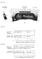
FIG. 5 is a view showing a die position generating cracks in contrast with predicted results of conventional FLD and results in press forming when steel sheet A in Table 1 is press-formed; -
FIG. 6 is a view showing a die position generating cracks in contrast with predicted values of conventional FLD and results in press forming when steel sheet B in Table 1 is press-formed; -
FIG. 7 is a view illustrating a form of a test specimen used in the preparation of FLD in examples; -
FIG. 8 is a graph showing an influence of a distance between reference points in marking upon maximum principal strain to be measured; -
FIG. 9 is a view showing a sectional form (crack form) of a test specimen after bulging; -
FIG. 10 is a view illustrating a shell element used in press forming simulation; -
FIG. 11 is a view illustrating a punch used in examples, wherein (a) is a punch used in the conventional FLD preparation and (b) is a punch used in the FLD preparation of the invention; -
FIG. 12 is a view showing a comparison between the conventional FLD and the invention FLD obtained in examples; -
FIG. 13 is a view plotted on FLD how to change maximum principal strain and minimum principal strain in accordance with a distance from a bottom center point of a die as to a position of crack generation when a steel sheet B in Table 1 is press-formed; and -
FIG. 14 is a view showing crack generating die positions predicted from the conventional FLD and the invention FLD in contrast with crack generating die position in press forming. - The basic technological idea of the invention will be described below.
- The inventors have noticed that breakage is frequently observed in press forming without constriction (necking) as a tensile strength TS of a steel sheet is increased to 980 MPa or 1180 MPa grade and becomes higher in the strength harder during the studies on the press forming of high-strength steel sheets. Referring to
FIG. 3 on this phenomenon, for example, when a low-strength and soft steel sheet is bulged with a round head punch, it is common that as shown inFIG. 3(a) , necking is locally caused and an amount of thickness decreased in the necking portion is increased to cause crack. In the high-strength and hard steel sheets having a tensile strength TS of 980 MPa or 1180 MPa grade, however, as shown inFIG. 3(b) , it has been confirmed that crack is generated from the surface of the steel sheet and runs into breakage at once. - In the high-strength steel sheet showing the above cracking behavior, it has been confirmed that when the crack generation is predicted by using the conventional FLD, even if the prediction result of no crack is obtained, cracks are generated in the actual press forming, and are particularly frequent at a site(s) having a large bending deformation.
- Then, the inventors have checked a position of a die generating cracks (distance from bottom dead center) when two kinds of steel sheets A and B shown in Table 1 having approximately equal tensile strength TS and elongation El and largely different bendability are press-formed into a simulated part form corresponding to a connecting portion of a roof rail at a top of a center pillar for an automobile shown in
FIG. 4 with a die (model die) comprised of an upper die and a lower die. The results are shown inFIGS. 5 and 6 in contrast with a position of a die generating cracks predicted with the conventional FLD prepared from maximum principal strain and minimum principal strain in thickness center. Moreover, the position of the steel sheet generating cracks in the press forming corresponds to a site subjected to severe bending work.Table 1 Symbol of steel sheet Thickness (mm) Yield stress YS (MPa) Tensile strength TS (MPa) Elongation El (%) Limit bending radius(*) (90° bending) (mm) Limit bending radius/thickness A 1.62 860 1085 14.5 1.5 0.9 B 1.64 740 1180 15.0 4.0 2.4 * : maximum bending radius generating cracks -
FIG. 5 shows results of the steel sheet A having an excellent bendability, in which the position of the die at the generation of cracks predicted from FLD prepared by the conventional method is coincident with the position of the die generating cracks in the press forming. InFIG. 6 showing the results of the steel sheet B having poor bendability, however, the position of the die at the generation of cracks predicted from FLD prepared by the conventional method is largely shifted from the position of the die generating cracks in the press forming, which results in poor prediction accuracy. - From the above results, it can be seen that the high-strength steel sheets being strengthened and hardened have two kinds of cracks generated at the sites strongly subjected to bending deformation in the press forming, i.e. crack resulted from progress of thickness reduction in a portion generating local constriction (hereinafter referred to as "crack dominated by ductility") and crack resulted from the generation of crack on the surface of the steel sheet without reduction of thickness and the propagation in thickness direction at once (hereinafter referred to as "crack dominated by bendability") and that when the latter crack dominated by bendability is caused, the prediction accuracy is largely deteriorated in the crack prediction method using the conventional FLD.
- Now, the inventors have examined how to solve problems in the conventional method for predicting cracks dominated by ductility and precisely predict crack generation. As a result, it has been found out that crack generation can be precisely predicted by preparing FLD considered with bendability in addition to the conventional FLD only considered with ductility and at the same time determining surface strain (maximum principal strain, minimum principal strain) at each element through press forming simulation using a finite element method and predicting cracks from a comparison between the above FLDs and the surface strain and that in order to prepare the FLD considered with bendability, it is enough to conduct bulging with a punch having a small curvature radius at its top and to determine maximum principal strain and minimum principal strain when surface strain in the generation of cracks on the surface of the steel sheet is defined as a forming limit.
- The invention is based on the above new knowledge.
- The invention will be described concretely by using a steel sheet as an example of a material to be press-formed (metal plate). Moreover, the invention is applicable to not only the steel sheet but also metal plates made from non-ferrous metal.
- At first, the steel sheet targeted in the invention is preferable to have a thickness of 0.6-3 mm and a ratio of limit bending radius to thickness in 90° bending (V-bending) (limit bending radius/thickness) of not less than 1.0. When the thickness is outside the above range, the chance for press forming is less, and when the ratio of limit bending radius/thickness is less than 1.0, the bendability is good and cracks dominated by ductility is caused, so that the use of the invention is needless.
- In the preparation of the forming limit diagram FLD considered with the bendability of the steel sheet, the steel sheet is shaped into test specimens having various widths within a range of 10-100 mm as shown in
FIG. 7 . The reason why test specimens are variously provided by changing the width is due to the fact that strain ratio (ratio of minimum principal strain to maximum principal strain) is widely changed. - Then, the surface of the test specimen is subjected to marking at a distance between reference points of 0.5-1.0 mm. The marking form (marking pattern) may be any form of circle pattern, dot pattern, grid pattern, concentric pattern and so on as long as strain quantity can be measured after the shaping. Also, the marking method may use any method of electrolytic etching, photo-etching, transcription with an ink (stamp printing) and so on, but marking-off is unfavorable because crack generation is induced. Moreover, the distance between reference points means a distance between centers of individual marking patterns. The reason why the distance between reference points is limited to 0.5-1.0 mm is mentioned later.
- Next, the test specimen is bulged with a punch having a minimum curvature radius at its top of 3-10 mm. In this case, the bulging is conducted while observing the surface of the test specimen (steel sheet) at the top portion of the punch with a stereoscopic microscope, an optical microscope, a laser displacement gauge or the like. The bulging is stopped at a time that cracks are generated on the surface of the steel sheet. The top form of the punch may be any form of sphere, ellipsoidal sphere, V-shaped and the like as long as the minimum curvature radius at its top is 3-10 mm. Moreover, the reason why the minimum curvature radius at the top of the punch is limited to 3-10 mm is due to the fact that when it is less than 3 mm, strain change in the deformation region of the top portion of the punch becomes too large and it is difficult to precisely measure principal strains at the distance between reference points in marking, while when it exceeds 10 mm, the influence of the bending deformation becomes weak as mentioned later.
- After the completion of the bulging, the marking position or form change at a crack-generating portion contacted with the top of the punch is measured to determine maximum principal strain and minimum principal strain at a time of generating cracks. This measurement is conducted repeatedly on the test specimens having various widths, whereby the maximum principal strain and minimum principal strain at a time of maximum principal strain and minimum principal strain at a time of generating cracks can be obtained widely. The thus obtained results measured on the maximum principal strain and the minimum principal strain are represented in a two-dimension to obtain a forming limit curve FLC.
- The reason when the distance between reference points is limited to 0.5-1.0 mm is described here.
- From the steel sheet B of the above Table 1 are provided test specimens having a width of 40 mm and a distance between reference points in marking variously changed within a range of 0.5-3.0 mm, which are bulged with an ellipsoidal head punch having a minimum curvature radius at its top of 10 mm as mentioned above to measure maximum principal strain at a time of generating cracks. The measured results are shown in
FIG. 8 as a relation between distance between reference points in marking and maximum principal strain measured. As seen from these results, when the distance between reference points in marking is made larger than 1.0 mm, the maximum principal strain is measured small and the measurement accuracy is deteriorated. While, when the distance between reference points is made smaller than 0.5 mm, the marking is difficult and further the measuring error on the position of reference point in marking becomes large and the measuring accuracy of principal strain lowers. In the invention, therefore, the distance between reference points is a range of 0.5-1.0 mm. - The reason why the minimum curvature radius at the top of the punch is limited not more than 10 mm is described below.
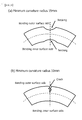
FIG. 9 is a schematic view illustrating crack form when the test specimen taken out from the steel sheet B of Table 1 is bulged with ellipsoidal head punches having minimum curvature radii of 15 mm and 10 mm, respectively. When the minimum curvature radius at the top of the punch is 10 mm, the crack generated from the surface of the test specimen as shown inFIG. 9(b) is the form of crack dominated by bendability, while when the bulging is conducted with a punch having a minimum curvature radius at its top of 15 mm, the crack resulted from the progress of thickness reduction in the generated local constriction is the form of crack dominated by ductility. Therefore, the minimum curvature radius at the top of the punch is not more than 10 mm resulting in the form of crack dominated by bendability. - The method for predicting crack generation in the press forming according to the invention is a method comprising steps of conducting simulation for press forming a steel sheet into a desired part form with a method using shell elements such as finite element method or the like, determining transition of maximum principal strain and minimum principal strain on the steel sheet surface in each element after the press forming or maximum principal strain and minimum principal strain on the steel sheet surface in each element during the press forming, plotting the thus obtained results on FLD separately prepared by the above method, confirming whether plots of maximum principal strain and minimum principal strain in each element are existent in a crack region across a forming limit curve FLC of the FLD or a non-crack region, and predicting crack generation if one or more elements are existent in the crack region. Moreover, the prediction on the presence or absence of crack is not necessarily carried out on all elements of the press-formed part. The crack prediction may be carried out by empirically squeezing the elements into a site concerning crack to be generated and determining maximum principal strain and minimum principal strain on the steel sheet surface in the element of this site.
- As the shell element in the above simulation can be used a shell element not considering elements in thickness direction because stress in the thickness direction can be generally ignored in case of thin steel sheets. Typically, model for simulation is frequently prepared at a position of the thickness center. For example, as shown in
FIG. 10 , points for calculating stress and strain (integration points) are set in each element, and integration points are also set at equal dividing positions of the thickness in the thickness direction. The maximum principal strain and minimum principal strain are calculated at the each integration point. The surface strain according to the invention means to be average value of maximum principal strains and average value of minimum principal strains calculated at the integration points on the surface of the metal plate, i.e. average value ofd s1 tod s4 described by symbols in the figure. Moreover, the number and position of the integration points are determined by kinds of elements used in the simulation. - The production method of press parts according to the invention is a method wherein cracks of a metal plate in press forming are predicted by the aforementioned crack prediction method, and if crack generation is predicted, press forming under such a condition (metal plate, die) is stopped and parts are produced by press forming after being changed to conditions causing no crack. Concretely, the press forming can be conducted under conditions causing no crack by changing a form of a die used in the press forming, or by changing the forming conditions such as pressing rate and temperature, lubrication state and so on, or by changing the material of the metal plate (ductility, bendability and the like).
- Several kinds of test specimens having a narrowest width of 10-100 mm are prepared by shaping the steel sheet B shown in the above Table 1 into a form shown in
FIG. 7 . On a surface of the test specimen is marked a dot pattern at a distance between reference points of 1.0 mm by an electrolytic etching. - Then, the test specimen is bulged with a spherical head punch having a top minimum curvature radius of 25 mm or an ellipsoidal head punch having a top minimum curvature radius of 7.5 mm as shown in
FIG. 11 . Moreover, the bulging with the ellipsoidal head punch is stopped at a stage of generating crack on the steel sheet surface by observing the steel sheet surface at the top portion of the punch with a stereoscopic microscope during the bulging. On the other hand, the bulging with the spherical head punch is continued until through crack is generated in the steel sheet. - Next, a change of dot distance in the vicinity of the punch top is measured on the test specimens after the bulging, from which maximum principal strain and minimum principal strain are determined to prepare FLD. Moreover, the FLD prepared using the spherical head punch corresponds to the conventional FLD indicating the forming limit strain at a thickness center, while the FLD prepared using the ellipsoidal head punch corresponds to FLD according to the invention considering the bending crack.
- In
FIG. 12 are shown FLDs prepared by the above two methods, respectively. However, the conventional FLD is a forming limit in the thickness center of the steel sheet, and the FLD of the invention is a forming limit in the surface of the steel sheet. - Then, the steel sheet B is press-formed into a simulated part form corresponding to a connecting portion of a roof rail at a top of a center pillar for an automobile shown in
FIG. 4 with a die (model die) comprised of an upper die and a lower die. As a result, it has been confirmed that cracks are generated at a position of 12 mm from a bottom dead center completely closing the upper die and the lower die to each other. - Aside the above press forming, three-dimensional press forming simulation in case of forming the steel sheet B is performed using a finite element method, and thickness center at a position of crack generation and transition of maximum principal strain and minimum principal strain on the steel sheet surface are determined in the forming way until the die reaches the bottom dead center. Moreover, LS-DYNA Ver 9.71 (made by LSTC: Livermore Software Technology Corporation) is used as an analysis software of the finite element method, wherein a shell element is square at the thickness center and an element size is 1.0 mm.
- Then, the transition of maximum principal strain and minimum principal strain in the forming way at the position of crack generation determined by the above simulation is plotted on the conventional FLD and the FLD of the invention shown in
FIG. 12 , respectively, from which a position of die generating cracks or a position from the bottom dead center of the die transferring the plots to a crack region over FLC of each FLD is determined to obtain results shown inFIG. 13 . In the conventional FLD, crack prediction is performed at the maximum principal strain and minimum principal strain at the thickness center, while in the FLD of the invention, the crack prediction is performed at the maximum principal strain and minimum principal strain on the steel sheet surface. - In
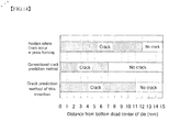
FIG. 14 is shown the result predicted on the position of the die generating cracks in contrast to the position of the die generating cracks in the press forming. As seen from this figure, the crack generation is predicted in the crack prediction using the conventional FLD when the die is descended from the bottom dead center to a position of 7 mm, whereas the crack generation is predicted in the crack prediction using the FLD of the invention when the die is descended from the bottom dead center to a position of 11 mm, which is substantially coincident with the position of die generating cracks actually found in the press forming (position of 12 mm from the bottom dead center). From these results, it can be seen that the prediction of crack generation using the FLD of the invention is good in the precision. - The invention is not limited to the aforementioned contents. For example, a case of applying to the steel sheet having a tensile strength of not less than 980 MPa grade (steel sheet of 1180 MPa grade) is shown in the above example. The invention is preferable to be applied to the press forming of such high-strength steel sheets, but is applicable to steel sheets having a tensile strength of less than 980 MPa grade or metal plates other than the steel sheet.
-
- 1: upper die of press die
- 2: lower die of press die
- 3: material to be formed (metal plate, steel sheet)
- 4: mesh division
- 5: element
Claims (3)
- A method for preparing a forming limit diagram in press forming, characterized in that a forming limit curve is obtained by subjecting a surface of a metal plate to be press-formed to marking at a distance between reference points of 0.5-1.0 mm, bulging the metal plate with a punch having a top minimum curvature radius of 3-10 mm and measuring a maximum principal strain and minimum principal strain at a time of generating cracks on the surface of the metal plate at a top portion of the punch from a change of the marking.
- A method for predicting crack in press forming, characterized in that crack generation in the press forming is predicted based on the forming limit diagram as claimed in claim 1.
- A method of producing press parts, characterized in that a metal plate is press-formed under conditions not causing crack by predicting the presence or absence of crack in the metal plate using a method for predicting crack in press forming as claimed in claim 2.
Applications Claiming Priority (1)
| Application Number | Priority Date | Filing Date | Title |
|---|---|---|---|
| PCT/JP2012/060216 WO2013157063A1 (en) | 2012-04-16 | 2012-04-16 | Method for drawing forming limit diagram for press forming, crack prediction method, and method for manufacturing pressed components |
Publications (3)
| Publication Number | Publication Date |
|---|---|
| EP2839896A4 EP2839896A4 (en) | 2015-02-25 |
| EP2839896A1 true EP2839896A1 (en) | 2015-02-25 |
| EP2839896B1 EP2839896B1 (en) | 2017-11-22 |
Family
ID=49383054
Family Applications (1)
| Application Number | Title | Priority Date | Filing Date |
|---|---|---|---|
| EP12874605.4A Not-in-force EP2839896B1 (en) | 2012-04-16 | 2012-04-16 | Method for preparing forming limit diagram in press forming, method for predicting crack and method of producing press parts |
Country Status (5)
| Country | Link |
|---|---|
| US (1) | US20150082855A1 (en) |
| EP (1) | EP2839896B1 (en) |
| KR (1) | KR20140131387A (en) |
| CN (1) | CN104220185B (en) |
| WO (1) | WO2013157063A1 (en) |
Families Citing this family (22)
| Publication number | Priority date | Publication date | Assignee | Title |
|---|---|---|---|---|
| US10670515B2 (en) * | 2013-05-20 | 2020-06-02 | Magna International Inc. | Detecting edge cracks |
| WO2014208697A1 (en) * | 2013-06-26 | 2014-12-31 | 新日鐵住金株式会社 | Method for determining bending fracture in metal plate, program, and storage medium |
| CN103852382B (en) * | 2014-03-04 | 2016-02-10 | 湖南大学 | A kind of method for building up of high strength steel plate thermoforming limiting figure |
| WO2016076965A1 (en) * | 2014-11-13 | 2016-05-19 | United States Of America, As Represented By The Administrator Of The National Aeronautics And Space Administration | Simulation tool for damage in composite laminates |
| JP6098664B2 (en) * | 2015-05-08 | 2017-03-22 | Jfeスチール株式会社 | Shear edge molding availability evaluation method |
| DE102016002889A1 (en) * | 2016-03-09 | 2017-09-14 | GM Global Technology Operations LLC (n. d. Ges. d. Staates Delaware) | Method for avoiding edge cracks |
| CN106018129B (en) * | 2016-05-16 | 2019-09-17 | 湖南大学 | A kind of evaluation method of auto parts and components drop stamping rupture performance |
| US11270047B2 (en) * | 2016-12-26 | 2022-03-08 | Nippon Steel Corporation | Metal sheet forming method, intermediate shape design method, metal sheet forming die, computer program, and recording medium |
| CN107622145B (en) * | 2017-08-18 | 2020-09-25 | 上海博汇模具有限公司 | Method for homogenizing flow velocity of profile water pipe of thermoforming mold |
| JP6886178B2 (en) * | 2017-08-24 | 2021-06-16 | 株式会社キーレックス | Preliminary prediction method for the presence or absence of cracks during molding of a press-molded product |
| JP6650959B2 (en) * | 2018-03-08 | 2020-02-19 | ユニプレス株式会社 | Rupture prediction method, fracture prediction device, and program |
| CN109470559B (en) * | 2018-09-10 | 2020-07-17 | 上海交通大学 | DIC-based necking failure limit strain detection method |
| CN113167572A (en) * | 2018-12-04 | 2021-07-23 | 优尼冲压株式会社 | Method for judging necking of press-formed products, device for judging necking of press-formed products, and program |
| CN113453818B (en) * | 2019-02-26 | 2023-11-28 | 杰富意钢铁株式会社 | Bending crack evaluation method, system therefor and manufacturing method of stamped formed parts |
| CN109870362B (en) * | 2019-03-04 | 2020-04-03 | 燕山大学 | A method and system for establishing fracture forming limit diagram of high-strength aluminum alloy sheet |
| DE112020007617T5 (en) * | 2020-09-16 | 2023-07-06 | Mitsubishi Electric Corporation | CRACK ESTIMATION DEVICE AND CRACK ESTIMATION METHOD |
| JP7218783B1 (en) * | 2021-09-10 | 2023-02-07 | Jfeスチール株式会社 | Press forming crack determination method, press forming crack determining device, press forming crack determining program, and press forming crack suppressing method |
| JP7452520B2 (en) * | 2021-11-12 | 2024-03-19 | Jfeスチール株式会社 | Press molding crack determination method, press molding crack determination device, press molding crack determination program, and press molding crack suppression method |
| US12036598B2 (en) * | 2022-04-04 | 2024-07-16 | Ford Global Technologies, Llc | Method and system for lubricating and forming a metal component from sheet metal |
| CN117250058A (en) * | 2022-06-10 | 2023-12-19 | 宝山钢铁股份有限公司 | Double tension fracture test stamping die |
| US12350725B2 (en) * | 2023-06-22 | 2025-07-08 | GM Global Technology Operations LLC | Components produced from metallic blanks and methods for producing the same |
| CN119259790B (en) * | 2024-12-05 | 2025-03-04 | 湖南高创翔宇科技有限公司 | Manufacturing process of variable-curvature thin-wall micro-channel structure |
Family Cites Families (13)
| Publication number | Priority date | Publication date | Assignee | Title |
|---|---|---|---|---|
| JP3720154B2 (en) * | 1996-12-02 | 2005-11-24 | 日新製鋼株式会社 | Austenitic stainless steel with excellent polishability after press working |
| US6550302B1 (en) * | 1999-07-27 | 2003-04-22 | The Regents Of The University Of Michigan | Sheet metal stamping die design for warm forming |
| US8990028B2 (en) * | 2006-02-01 | 2015-03-24 | Nippon Steel & Sumitomo Metal Corporation | Fracture prediction method, device, a program arrangement and computer-accessible medium therefor |
| JP4795176B2 (en) | 2006-09-01 | 2011-10-19 | 富士重工業株式会社 | Mold temperature simulation method and simulation program |
| JP4865489B2 (en) * | 2006-10-04 | 2012-02-01 | 本田技研工業株式会社 | Molding speed determination method |
| JP4814831B2 (en) * | 2007-04-25 | 2011-11-16 | 新日本製鐵株式会社 | Stretch flangeability evaluation test method in sheet metal press forming |
| US8042405B2 (en) * | 2008-07-23 | 2011-10-25 | University Of Kentucky Research Foundation | Method and apparatus for characterizing microscale formability of thin sheet materials |
| JP5146395B2 (en) * | 2008-08-20 | 2013-02-20 | 新日鐵住金株式会社 | Stretch flange crack estimation method considering strain gradient and stretch flange crack judgment system of press forming simulation |
| JP5435352B2 (en) * | 2010-01-08 | 2014-03-05 | 新日鐵住金株式会社 | Method for determining the breaking strain of plate materials |
| JP5434622B2 (en) * | 2010-01-20 | 2014-03-05 | 新日鐵住金株式会社 | Break determination method and break determination apparatus in press forming simulation of thin plate |
| US20110295570A1 (en) * | 2010-05-27 | 2011-12-01 | Livermore Software Technology Corporation | Sheet Metal Forming Failure Prediction Using Numerical Simulations |
| JP2012011458A (en) * | 2010-05-31 | 2012-01-19 | Jfe Steel Corp | Crack determination method in press forming simulation, and method of manufacturing press formed component using the same |
| JP5445381B2 (en) * | 2010-07-30 | 2014-03-19 | 新日鐵住金株式会社 | Method and apparatus for predicting bending fracture of material, program, and recording medium |
-
2012
- 2012-04-16 CN CN201280072402.1A patent/CN104220185B/en not_active Expired - Fee Related
- 2012-04-16 KR KR1020147027766A patent/KR20140131387A/en not_active Ceased
- 2012-04-16 WO PCT/JP2012/060216 patent/WO2013157063A1/en not_active Ceased
- 2012-04-16 US US14/394,570 patent/US20150082855A1/en not_active Abandoned
- 2012-04-16 EP EP12874605.4A patent/EP2839896B1/en not_active Not-in-force
Also Published As
| Publication number | Publication date |
|---|---|
| EP2839896A4 (en) | 2015-02-25 |
| WO2013157063A1 (en) | 2013-10-24 |
| US20150082855A1 (en) | 2015-03-26 |
| CN104220185A (en) | 2014-12-17 |
| KR20140131387A (en) | 2014-11-12 |
| CN104220185B (en) | 2017-09-26 |
| EP2839896B1 (en) | 2017-11-22 |
Similar Documents
| Publication | Publication Date | Title |
|---|---|---|
| EP2839896B1 (en) | Method for preparing forming limit diagram in press forming, method for predicting crack and method of producing press parts | |
| JP5630312B2 (en) | Forming limit diagram creation method, crack prediction method and press part manufacturing method in press forming | |
| JP5630311B2 (en) | Method for predicting cracks in press molding and method for manufacturing pressed parts | |
| KR102334109B1 (en) | Evaluation method of deformation limit in shearing surface of metal plate, crack prediction method, and design method of press mold | |
| KR102271009B1 (en) | Evaluation method of deformation limit in shearing surface of metal plate, crack prediction method, and design method of press mold | |
| Elyasi et al. | Manufacturing metallic bipolar plate fuel cells through rubber pad forming process | |
| KR102345288B1 (en) | Methods for evaluating deformation limits, predicting cracks and designing press molds | |
| CN104010745B (en) | Die Design Method for Press Forming, Die for Press Forming | |
| JP6870670B2 (en) | Deformation limit evaluation method, crack prediction method and press die design method | |
| KR20150043476A (en) | Springback amount evaluation method | |
| JP6773255B1 (en) | Bending crack evaluation method, bending crack evaluation system, and manufacturing method of press-formed parts | |
| JP2012011458A (en) | Crack determination method in press forming simulation, and method of manufacturing press formed component using the same | |
| JP7288212B2 (en) | Blank manufacturing method, press-formed product manufacturing method, shape determining method, shape determining program, blank manufacturing apparatus, and blank | |
| JP7647800B2 (en) | PRESS FORMING ANALYSIS METHOD, PRESS FORMING CRACK DETECTION METHOD FOR PRESS FORMED PRODUCT, MANUFACTURING METHOD FOR PRESS FORMED PRODUCT, PRESS FORMING ANALYSIS DEVICE, PRESS FORMING ANALYSIS PROGRAM | |
| JP5900751B2 (en) | Evaluation method and prediction method of bending inner crack | |
| KR20250040993A (en) | Press forming analysis method, press forming crack determination method of press forming product, manufacturing method of press forming product, press forming analysis device, press forming analysis program | |
| CN104155177B (en) | A kind of super-high strength steel thin plate pre-punching process performance test sample and method of testing thereof | |
| JP5375942B2 (en) | Metal plate for press forming | |
| JP7722533B1 (en) | Manufacturing method for press-molded products | |
| CN120460587A (en) | A method for evaluating edge cracking of high-strength steel using hole expansion limit strain |
Legal Events
| Date | Code | Title | Description |
|---|---|---|---|
| PUAI | Public reference made under article 153(3) epc to a published international application that has entered the european phase |
Free format text: ORIGINAL CODE: 0009012 |
|
| 17P | Request for examination filed |
Effective date: 20141112 |
|
| A4 | Supplementary search report drawn up and despatched |
Effective date: 20141205 |
|
| AK | Designated contracting states |
Kind code of ref document: A1 Designated state(s): AL AT BE BG CH CY CZ DE DK EE ES FI FR GB GR HR HU IE IS IT LI LT LU LV MC MK MT NL NO PL PT RO RS SE SI SK SM TR |
|
| AX | Request for extension of the european patent |
Extension state: BA ME |
|
| DAX | Request for extension of the european patent (deleted) | ||
| STAA | Information on the status of an ep patent application or granted ep patent |
Free format text: STATUS: EXAMINATION IS IN PROGRESS |
|
| 17Q | First examination report despatched |
Effective date: 20161207 |
|
| GRAP | Despatch of communication of intention to grant a patent |
Free format text: ORIGINAL CODE: EPIDOSNIGR1 |
|
| STAA | Information on the status of an ep patent application or granted ep patent |
Free format text: STATUS: GRANT OF PATENT IS INTENDED |
|
| INTG | Intention to grant announced |
Effective date: 20170609 |
|
| GRAS | Grant fee paid |
Free format text: ORIGINAL CODE: EPIDOSNIGR3 |
|
| GRAA | (expected) grant |
Free format text: ORIGINAL CODE: 0009210 |
|
| STAA | Information on the status of an ep patent application or granted ep patent |
Free format text: STATUS: THE PATENT HAS BEEN GRANTED |
|
| AK | Designated contracting states |
Kind code of ref document: B1 Designated state(s): AL AT BE BG CH CY CZ DE DK EE ES FI FR GB GR HR HU IE IS IT LI LT LU LV MC MK MT NL NO PL PT RO RS SE SI SK SM TR |
|
| REG | Reference to a national code |
Ref country code: GB Ref legal event code: FG4D |
|
| REG | Reference to a national code |
Ref country code: CH Ref legal event code: EP |
|
| REG | Reference to a national code |
Ref country code: IE Ref legal event code: FG4D |
|
| REG | Reference to a national code |
Ref country code: AT Ref legal event code: REF Ref document number: 947931 Country of ref document: AT Kind code of ref document: T Effective date: 20171215 |
|
| REG | Reference to a national code |
Ref country code: DE Ref legal event code: R096 Ref document number: 602012040214 Country of ref document: DE |
|
| REG | Reference to a national code |
Ref country code: NL Ref legal event code: MP Effective date: 20171122 |
|
| REG | Reference to a national code |
Ref country code: LT Ref legal event code: MG4D |
|
| REG | Reference to a national code |
Ref country code: AT Ref legal event code: MK05 Ref document number: 947931 Country of ref document: AT Kind code of ref document: T Effective date: 20171122 |
|
| REG | Reference to a national code |
Ref country code: FR Ref legal event code: PLFP Year of fee payment: 7 |
|
| PG25 | Lapsed in a contracting state [announced via postgrant information from national office to epo] |
Ref country code: LT Free format text: LAPSE BECAUSE OF FAILURE TO SUBMIT A TRANSLATION OF THE DESCRIPTION OR TO PAY THE FEE WITHIN THE PRESCRIBED TIME-LIMIT Effective date: 20171122 Ref country code: NL Free format text: LAPSE BECAUSE OF FAILURE TO SUBMIT A TRANSLATION OF THE DESCRIPTION OR TO PAY THE FEE WITHIN THE PRESCRIBED TIME-LIMIT Effective date: 20171122 Ref country code: FI Free format text: LAPSE BECAUSE OF FAILURE TO SUBMIT A TRANSLATION OF THE DESCRIPTION OR TO PAY THE FEE WITHIN THE PRESCRIBED TIME-LIMIT Effective date: 20171122 Ref country code: NO Free format text: LAPSE BECAUSE OF FAILURE TO SUBMIT A TRANSLATION OF THE DESCRIPTION OR TO PAY THE FEE WITHIN THE PRESCRIBED TIME-LIMIT Effective date: 20180222 Ref country code: SE Free format text: LAPSE BECAUSE OF FAILURE TO SUBMIT A TRANSLATION OF THE DESCRIPTION OR TO PAY THE FEE WITHIN THE PRESCRIBED TIME-LIMIT Effective date: 20171122 Ref country code: ES Free format text: LAPSE BECAUSE OF FAILURE TO SUBMIT A TRANSLATION OF THE DESCRIPTION OR TO PAY THE FEE WITHIN THE PRESCRIBED TIME-LIMIT Effective date: 20171122 |
|
| PG25 | Lapsed in a contracting state [announced via postgrant information from national office to epo] |
Ref country code: HR Free format text: LAPSE BECAUSE OF FAILURE TO SUBMIT A TRANSLATION OF THE DESCRIPTION OR TO PAY THE FEE WITHIN THE PRESCRIBED TIME-LIMIT Effective date: 20171122 Ref country code: BG Free format text: LAPSE BECAUSE OF FAILURE TO SUBMIT A TRANSLATION OF THE DESCRIPTION OR TO PAY THE FEE WITHIN THE PRESCRIBED TIME-LIMIT Effective date: 20180222 Ref country code: LV Free format text: LAPSE BECAUSE OF FAILURE TO SUBMIT A TRANSLATION OF THE DESCRIPTION OR TO PAY THE FEE WITHIN THE PRESCRIBED TIME-LIMIT Effective date: 20171122 Ref country code: AT Free format text: LAPSE BECAUSE OF FAILURE TO SUBMIT A TRANSLATION OF THE DESCRIPTION OR TO PAY THE FEE WITHIN THE PRESCRIBED TIME-LIMIT Effective date: 20171122 Ref country code: GR Free format text: LAPSE BECAUSE OF FAILURE TO SUBMIT A TRANSLATION OF THE DESCRIPTION OR TO PAY THE FEE WITHIN THE PRESCRIBED TIME-LIMIT Effective date: 20180223 Ref country code: RS Free format text: LAPSE BECAUSE OF FAILURE TO SUBMIT A TRANSLATION OF THE DESCRIPTION OR TO PAY THE FEE WITHIN THE PRESCRIBED TIME-LIMIT Effective date: 20171122 |
|
| PG25 | Lapsed in a contracting state [announced via postgrant information from national office to epo] |
Ref country code: DK Free format text: LAPSE BECAUSE OF FAILURE TO SUBMIT A TRANSLATION OF THE DESCRIPTION OR TO PAY THE FEE WITHIN THE PRESCRIBED TIME-LIMIT Effective date: 20171122 Ref country code: CY Free format text: LAPSE BECAUSE OF FAILURE TO SUBMIT A TRANSLATION OF THE DESCRIPTION OR TO PAY THE FEE WITHIN THE PRESCRIBED TIME-LIMIT Effective date: 20171122 Ref country code: EE Free format text: LAPSE BECAUSE OF FAILURE TO SUBMIT A TRANSLATION OF THE DESCRIPTION OR TO PAY THE FEE WITHIN THE PRESCRIBED TIME-LIMIT Effective date: 20171122 Ref country code: SK Free format text: LAPSE BECAUSE OF FAILURE TO SUBMIT A TRANSLATION OF THE DESCRIPTION OR TO PAY THE FEE WITHIN THE PRESCRIBED TIME-LIMIT Effective date: 20171122 Ref country code: CZ Free format text: LAPSE BECAUSE OF FAILURE TO SUBMIT A TRANSLATION OF THE DESCRIPTION OR TO PAY THE FEE WITHIN THE PRESCRIBED TIME-LIMIT Effective date: 20171122 |
|
| REG | Reference to a national code |
Ref country code: DE Ref legal event code: R097 Ref document number: 602012040214 Country of ref document: DE |
|
| PG25 | Lapsed in a contracting state [announced via postgrant information from national office to epo] |
Ref country code: IT Free format text: LAPSE BECAUSE OF FAILURE TO SUBMIT A TRANSLATION OF THE DESCRIPTION OR TO PAY THE FEE WITHIN THE PRESCRIBED TIME-LIMIT Effective date: 20171122 Ref country code: RO Free format text: LAPSE BECAUSE OF FAILURE TO SUBMIT A TRANSLATION OF THE DESCRIPTION OR TO PAY THE FEE WITHIN THE PRESCRIBED TIME-LIMIT Effective date: 20171122 Ref country code: SM Free format text: LAPSE BECAUSE OF FAILURE TO SUBMIT A TRANSLATION OF THE DESCRIPTION OR TO PAY THE FEE WITHIN THE PRESCRIBED TIME-LIMIT Effective date: 20171122 Ref country code: PL Free format text: LAPSE BECAUSE OF FAILURE TO SUBMIT A TRANSLATION OF THE DESCRIPTION OR TO PAY THE FEE WITHIN THE PRESCRIBED TIME-LIMIT Effective date: 20171122 |
|
| PLBE | No opposition filed within time limit |
Free format text: ORIGINAL CODE: 0009261 |
|
| STAA | Information on the status of an ep patent application or granted ep patent |
Free format text: STATUS: NO OPPOSITION FILED WITHIN TIME LIMIT |
|
| 26N | No opposition filed |
Effective date: 20180823 |
|
| PG25 | Lapsed in a contracting state [announced via postgrant information from national office to epo] |
Ref country code: SI Free format text: LAPSE BECAUSE OF FAILURE TO SUBMIT A TRANSLATION OF THE DESCRIPTION OR TO PAY THE FEE WITHIN THE PRESCRIBED TIME-LIMIT Effective date: 20171122 Ref country code: MC Free format text: LAPSE BECAUSE OF FAILURE TO SUBMIT A TRANSLATION OF THE DESCRIPTION OR TO PAY THE FEE WITHIN THE PRESCRIBED TIME-LIMIT Effective date: 20171122 |
|
| REG | Reference to a national code |
Ref country code: CH Ref legal event code: PL |
|
| REG | Reference to a national code |
Ref country code: BE Ref legal event code: MM Effective date: 20180430 |
|
| REG | Reference to a national code |
Ref country code: IE Ref legal event code: MM4A |
|
| PG25 | Lapsed in a contracting state [announced via postgrant information from national office to epo] |
Ref country code: LU Free format text: LAPSE BECAUSE OF NON-PAYMENT OF DUE FEES Effective date: 20180416 |
|
| PG25 | Lapsed in a contracting state [announced via postgrant information from national office to epo] |
Ref country code: CH Free format text: LAPSE BECAUSE OF NON-PAYMENT OF DUE FEES Effective date: 20180430 Ref country code: BE Free format text: LAPSE BECAUSE OF NON-PAYMENT OF DUE FEES Effective date: 20180430 Ref country code: LI Free format text: LAPSE BECAUSE OF NON-PAYMENT OF DUE FEES Effective date: 20180430 |
|
| PG25 | Lapsed in a contracting state [announced via postgrant information from national office to epo] |
Ref country code: IE Free format text: LAPSE BECAUSE OF NON-PAYMENT OF DUE FEES Effective date: 20180416 |
|
| PGFP | Annual fee paid to national office [announced via postgrant information from national office to epo] |
Ref country code: GB Payment date: 20190410 Year of fee payment: 8 |
|
| PG25 | Lapsed in a contracting state [announced via postgrant information from national office to epo] |
Ref country code: MT Free format text: LAPSE BECAUSE OF NON-PAYMENT OF DUE FEES Effective date: 20180416 |
|
| PG25 | Lapsed in a contracting state [announced via postgrant information from national office to epo] |
Ref country code: TR Free format text: LAPSE BECAUSE OF FAILURE TO SUBMIT A TRANSLATION OF THE DESCRIPTION OR TO PAY THE FEE WITHIN THE PRESCRIBED TIME-LIMIT Effective date: 20171122 |
|
| PG25 | Lapsed in a contracting state [announced via postgrant information from national office to epo] |
Ref country code: PT Free format text: LAPSE BECAUSE OF FAILURE TO SUBMIT A TRANSLATION OF THE DESCRIPTION OR TO PAY THE FEE WITHIN THE PRESCRIBED TIME-LIMIT Effective date: 20171122 Ref country code: HU Free format text: LAPSE BECAUSE OF FAILURE TO SUBMIT A TRANSLATION OF THE DESCRIPTION OR TO PAY THE FEE WITHIN THE PRESCRIBED TIME-LIMIT; INVALID AB INITIO Effective date: 20120416 |
|
| PG25 | Lapsed in a contracting state [announced via postgrant information from national office to epo] |
Ref country code: MK Free format text: LAPSE BECAUSE OF NON-PAYMENT OF DUE FEES Effective date: 20171122 |
|
| PG25 | Lapsed in a contracting state [announced via postgrant information from national office to epo] |
Ref country code: AL Free format text: LAPSE BECAUSE OF FAILURE TO SUBMIT A TRANSLATION OF THE DESCRIPTION OR TO PAY THE FEE WITHIN THE PRESCRIBED TIME-LIMIT Effective date: 20171122 Ref country code: IS Free format text: LAPSE BECAUSE OF FAILURE TO SUBMIT A TRANSLATION OF THE DESCRIPTION OR TO PAY THE FEE WITHIN THE PRESCRIBED TIME-LIMIT Effective date: 20180322 |
|
| REG | Reference to a national code |
Ref country code: DE Ref legal event code: R082 Ref document number: 602012040214 Country of ref document: DE Representative=s name: HL KEMPNER PATENTANWAELTE, SOLICITORS (ENGLAND, DE Ref country code: DE Ref legal event code: R082 Ref document number: 602012040214 Country of ref document: DE Representative=s name: HL KEMPNER PATENTANWALT, RECHTSANWALT, SOLICIT, DE Ref country code: DE Ref legal event code: R082 Ref document number: 602012040214 Country of ref document: DE Representative=s name: HL KEMPNER PARTG MBB, DE |
|
| GBPC | Gb: european patent ceased through non-payment of renewal fee |
Effective date: 20200416 |
|
| PG25 | Lapsed in a contracting state [announced via postgrant information from national office to epo] |
Ref country code: GB Free format text: LAPSE BECAUSE OF NON-PAYMENT OF DUE FEES Effective date: 20200416 |
|
| PGFP | Annual fee paid to national office [announced via postgrant information from national office to epo] |
Ref country code: FR Payment date: 20240308 Year of fee payment: 13 |
|
| PGFP | Annual fee paid to national office [announced via postgrant information from national office to epo] |
Ref country code: DE Payment date: 20240227 Year of fee payment: 13 |
|
| REG | Reference to a national code |
Ref country code: DE Ref legal event code: R119 Ref document number: 602012040214 Country of ref document: DE |
|
| PG25 | Lapsed in a contracting state [announced via postgrant information from national office to epo] |
Ref country code: DE Free format text: LAPSE BECAUSE OF NON-PAYMENT OF DUE FEES Effective date: 20251104 |
|
| PG25 | Lapsed in a contracting state [announced via postgrant information from national office to epo] |
Ref country code: FR Free format text: LAPSE BECAUSE OF NON-PAYMENT OF DUE FEES Effective date: 20250430 |