EP2839718B1 - A lighting device, a method of controlling the same, for selectively emitting light along or against traffic direction - Google Patents
A lighting device, a method of controlling the same, for selectively emitting light along or against traffic direction Download PDFInfo
- Publication number
- EP2839718B1 EP2839718B1 EP13762575.2A EP13762575A EP2839718B1 EP 2839718 B1 EP2839718 B1 EP 2839718B1 EP 13762575 A EP13762575 A EP 13762575A EP 2839718 B1 EP2839718 B1 EP 2839718B1
- Authority
- EP
- European Patent Office
- Prior art keywords
- lighting
- predetermined condition
- road surface
- light beam
- radiate
- Prior art date
- Legal status (The legal status is an assumption and is not a legal conclusion. Google has not performed a legal analysis and makes no representation as to the accuracy of the status listed.)
- Active
Links
Images


Classifications
-
- F—MECHANICAL ENGINEERING; LIGHTING; HEATING; WEAPONS; BLASTING
- F21—LIGHTING
- F21V—FUNCTIONAL FEATURES OR DETAILS OF LIGHTING DEVICES OR SYSTEMS THEREOF; STRUCTURAL COMBINATIONS OF LIGHTING DEVICES WITH OTHER ARTICLES, NOT OTHERWISE PROVIDED FOR
- F21V14/00—Controlling the distribution of the light emitted by adjustment of elements
- F21V14/02—Controlling the distribution of the light emitted by adjustment of elements by movement of light sources
-
- F—MECHANICAL ENGINEERING; LIGHTING; HEATING; WEAPONS; BLASTING
- F21—LIGHTING
- F21S—NON-PORTABLE LIGHTING DEVICES; SYSTEMS THEREOF; VEHICLE LIGHTING DEVICES SPECIALLY ADAPTED FOR VEHICLE EXTERIORS
- F21S8/00—Lighting devices intended for fixed installation
- F21S8/08—Lighting devices intended for fixed installation with a standard
- F21S8/085—Lighting devices intended for fixed installation with a standard of high-built type, e.g. street light
- F21S8/086—Lighting devices intended for fixed installation with a standard of high-built type, e.g. street light with lighting device attached sideways of the standard, e.g. for roads and highways
-
- H—ELECTRICITY
- H05—ELECTRIC TECHNIQUES NOT OTHERWISE PROVIDED FOR
- H05B—ELECTRIC HEATING; ELECTRIC LIGHT SOURCES NOT OTHERWISE PROVIDED FOR; CIRCUIT ARRANGEMENTS FOR ELECTRIC LIGHT SOURCES, IN GENERAL
- H05B47/00—Circuit arrangements for operating light sources in general, i.e. where the type of light source is not relevant
- H05B47/10—Controlling the light source
- H05B47/175—Controlling the light source by remote control
-
- F—MECHANICAL ENGINEERING; LIGHTING; HEATING; WEAPONS; BLASTING
- F21—LIGHTING
- F21W—INDEXING SCHEME ASSOCIATED WITH SUBCLASSES F21K, F21L, F21S and F21V, RELATING TO USES OR APPLICATIONS OF LIGHTING DEVICES OR SYSTEMS
- F21W2131/00—Use or application of lighting devices or systems not provided for in codes F21W2102/00-F21W2121/00
- F21W2131/10—Outdoor lighting
- F21W2131/103—Outdoor lighting of streets or roads
-
- Y—GENERAL TAGGING OF NEW TECHNOLOGICAL DEVELOPMENTS; GENERAL TAGGING OF CROSS-SECTIONAL TECHNOLOGIES SPANNING OVER SEVERAL SECTIONS OF THE IPC; TECHNICAL SUBJECTS COVERED BY FORMER USPC CROSS-REFERENCE ART COLLECTIONS [XRACs] AND DIGESTS
- Y02—TECHNOLOGIES OR APPLICATIONS FOR MITIGATION OR ADAPTATION AGAINST CLIMATE CHANGE
- Y02B—CLIMATE CHANGE MITIGATION TECHNOLOGIES RELATED TO BUILDINGS, e.g. HOUSING, HOUSE APPLIANCES OR RELATED END-USER APPLICATIONS
- Y02B20/00—Energy efficient lighting technologies, e.g. halogen lamps or gas discharge lamps
- Y02B20/72—Energy efficient lighting technologies, e.g. halogen lamps or gas discharge lamps in street lighting
Definitions
- the present invention relates to lighting, and particularly to a lighting device, a lighting apparatus comprising the lighting device, a lighting system comprising a plurality of lighting apparatuses and a method of controlling the lighting device.
- the energy saving of the lighting device should be taken into account.
- some intelligent lighting control systems take an energy-saving approach by reducing the power of road lighting at midnight with a sacrifice of average luminance level. Such an approach is based on the assumption that at midnight, the vehicle flow rate is relatively lower, so the visual tasks for drivers are easier, and a lower luminance level can be still sufficient.
- drivers tend to be tired and drowsy; therefore reducing the lighting level could lead to a risk of traffic accident.
- the main contributor is the light beam opposite to the observer rather than the light beam towards the observer.
- the car 110 i.e., object
- the light beam 121 opposite to the observer 140 outweigh the light beam 131 towards the observer 140.
- the second one is that, for illuminating the area of the road surface, using the light beam towards the observer can save much more energy than using the light beam opposite to the observer.
- the light beam 221 i.e., the light beam opposite to the observer 240
- the light beam 231 i.e., the light beam towards the observer 240
- the experiments conducted by the inventor show that the perceived luminance of area A is 3 times higher than that of area B by observer 240; therefore, to achieve the same lighting level on the road surface, illuminating the area A could save energy about three times than illuminating the area B.
- one embodiment of the invention provides a lighting device.
- the lighting device for road lighting comprises a lighting module; and a control module coupled to the lighting module, and configured to control the lighting module to radiate a first light beam towards a first direction to generate a first lighting pattern on the road surface, when a first predetermined condition is satisfied, and to control the lighting module to radiate a second light beam towards a second direction to generate a second lighting pattern on the road surface, when a second predetermined condition is satisfied, wherein the first direction is oriented to go along the traffic direction and the second direction is oriented to go opposite the traffic direction.
- the first predetermined condition comprises any one or more of:
- the lighting device of the present invention could generate the first light beam towards the first direction that goes along the traffic direction, when the first predetermined condition is satisfied, and generate the second light beam towards the second direction that goes opposite the traffic direction, when the second predetermined condition is satisfied.
- the lighting device is controlled to generate the first light beam towards the first direction.
- the first direction is oriented to go along the traffic direction, almost all the light beam of the lighting device is directed at the rear of the forward objects and thus the visibility of the forward objects is increased. Therefore, compared to the conventional lighting device with the same power, the lighting device of the present invention could increase the visibility of the forward objects on the road surface while reducing glaring, and thus ensure the traffic safety better.
- the lighting device When the current traffic flow is within the second flow range (e.g., in non rush time), the lighting device is controlled to generate the second light beam towards the second direction.
- the luminance on the road surface illuminated by the lighting device is much higher than that of the conventional lighting device with the same power.
- the power of the second light beam can be reduced, and thereby the energy saving of the lighting device is achieved.
- one embodiment of the invention provides a lighting apparatus.
- the lighting apparatus comprises a support mounted on the road surface and the lighting device according to the first aspect of this invention mounted on the support and oriented relative to the road surface such that the lighting apparatus radiates the first light beam towards the first direction to generate the first lighting pattern on the road surface when the first predetermined condition is satisfied, and radiate the second light beam towards the second direction to generate the second lighting pattern on the road surface when the second predetermined condition is satisfied.
- one embodiment of the invention provides a lighting system, comprises a plurality of lighting apparatuses according to the second aspect of this invention, wherein the support of each of the plurality of lighting apparatuses is configured to be mounted on the road surface and spaced apart one another such that the first lighting patterns of the plurality of lighting apparatuses cover the whole road surface, and the second lighting patterns of the plurality of lighting apparatuses cover the whole road surface.
- one embodiment of the invention provides a method of controlling the lighting device according to claim 1 to generate an illuminance on a road surface, the method comprising the steps of:
- FIG. 3 shows a side view of an application scenario to which a conventional lighting system is applied.
- three conventional lighting devices 350a, 350b and 350c are shown in FIG. 3 .
- each of the three conventional lighting devices 350a, 350b and 350c has a symmetrical light distribution and generates two lighting patterns A and B on the road surface.
- the lighting patterns A and B are symmetric about the support 370a, 370b, 370c on which the lighting device 350a, 350b, 350c is mounted.
- the lighting device, the lighting apparatus and the lighting system of embodiments of the invention are the improvement of the conventional lighting device, the conventional light apparatus and the conventional lighting system.
- FIG. 4 shows a block diagram of the lighting device according to one embodiment of the present invention.
- the lighting device 450 for road lighting comprises a lighting module 451 and a control module 455 coupled to the lighting module 451.
- the control module 455 is configured to control the lighting module 451 to radiate a first light beam towards a first direction to generate a first lighting pattern on the road surface, when a first predetermined condition is satisfied, and to control the lighting module 451 to radiate a second light beam towards a second direction to generate a second lighting pattern on the road surface, when a second predetermined condition is satisfied.
- the first direction is oriented to go along the traffic direction and the second direction is oriented to go opposite the traffic direction.
- the first predetermined condition and the second predetermined condition can be implemented in various scenarios.
- the first predetermined condition may be the current traffic flow of the road surface being within the first flow range
- the second predetermined condition may be the current traffic flow of the road surface being within the second flow range.
- the control module 455 may comprise a sensor and a processor coupled to the sensor. The sensor measures the current traffic flow and provides the outcome to the processor. The processor receives the outcome from the sensor and determines whether the current traffic flow is within the first flow range or within the second flow range based on the received outcome.
- the processor controls the lighting module 451 to radiate the first light beam towards the first direction. If the outcome indicates that the current traffic flow is within the second flow range, for example, from 0 to 300pcu/min, then the processor controls the lighting module 451 to radiate the second light beam towards the second direction.
- the sensor measures the current traffic flow periodically, for example, every 5 minutes.
- the first predetermined condition may be the current time being within the first time range
- the second predetermined condition may be the current time being within the second time range
- the control module 455 may comprise a timer and a processor coupled to the timer. The processor obtains the time value from the timer and determines whether the current time is within the first time range or within the second time range. If the time value indicates the current time is within the first time range, for example within the time range from 18:00 to 21:00, then the processor controls the lighting module 451 to radiate the first light beam towards the first direction. If the time value indicated the current time is within the second time range, for example within the time range from 21:00 to 5:00, then the processor controls the lighting module 451 to radiate the second light beam towards the second direction.
- the first predetermined condition may be a first trigger signal being received
- the second predetermined condition may be a second trigger signal being received.
- the first and second trigger signals may be generated by a manual switch and then provided to the control module 455 of the lighting device 450.
- the lighting module 551 may comprise two lighting units 552 and 553, as shown in FIG 5 .
- the first lighting unit 552 is controlled to radiate the first light beam towards the first direction;
- the second lighting unit 553 is controlled to radiate the second light beam towards the second direction.
- the lighting module 651 may comprise one lighting unit 652 and a driving unit 654, as shown in FIG 6 .
- the driving unit 654 is controlled to adjust the orientation of the lighting module 651 to radiate the first light beam towards the first direction; when the second predetermined condition is satisfied, the driving unit 654 is controlled to adjust the orientation of the lighting module 651 to radiate the second light beam towards the second direction.
- the driving unit may be a motor, for example.
- the lighting device 450 of FIG. 4 may be applicable to any suitable lighting scenario.
- the lighting device 450 may be mounted on a support to constitute a lighting apparatus.
- a plurality of lighting apparatuses may be mounted on the road surface and spaced apart one another to form a road lighting system, as shown in FIG 7 and FIG 8 .
- the road lighting system 700 of one embodiment of the invention will be described in detail using the current time being within the first time range as an example of the first predetermined condition and the current time being within the second time range as an example of the second predetermined condition.
- all the light devices 750a, 750b and 750c of the lighting system 700 are controlled to radiate the first light beams 720a, 720b and 720c towards the first direction, i.e., the direction that goes along the traffic direction 760, as shown in FIG. 7 . Since almost all light beams of the lighting devices 750a, 750b and 750c are directed at the rear of the forward objects and thus the visibility of the forward objects is increased. To be specific, for example, for the driver of the car 717, the light beam 720c from the lighting device 750c is directed at the rear of the forward car 716 and thus the visibility of the forward car 716 is increased.
- the lighting system 700 of the invention could increase, for drivers behind, the visibility of forward cars while reducing glaring, and thus ensure the traffic safety better.
- the lighting devices 750a, 750b and 750c of the lighting system 700 are controlled to radiate the second light beams 730a, 730b and 730c towards the second direction, i.e., the direction that goes opposite the traffic direction 760, as shown in FIG 8 . Since almost all light beams of the lighting devices 750a, 750b and 750c are directed to the second direction that goes opposite to the traffic direction 760, in order to generate the same lighting level, the lighting devices 750a, 750b and 750c of the lighting system 700 can consume less energy than that of the conventional lighting system of FIG. 3 .
- the power of the second lighting unit 553 can be set to be smaller than that of the first lighting unit 552. In this way, the energy saving of the lighting system 700 is achieved.
- the lighting devices 750a, 750b and 750c of the lighting system 700 are oriented with respect to the road surface such that the lighting patterns A 1 , A 2 and A 3 on the road surface are consecutive to-each other and the lighting pattern B 1 , B 2 and B 3 on the road surface are consecutive to each other, which means the lighting patterns of the lighting system 700 cover the whole road surface. In this way, a uniform illuminance can be achieved on the road surface.
- FIG. 9 shows a flow chart of a method of controlling a lighting device according to the present invention.
- the method of FIG 9 comprises Step 910 of determining whether a first predetermined condition is satisfied or a second predetermined condition is satisfied; and Step 920 of controlling the lighting device to radiate a first light beam towards a first direction to generate a first lighting pattern on the road surface when the first predetermined condition is satisfied, and controlling the lighting device to radiate a second light beam towards a second direction to generate a second lighting pattern on the road surface when the second predetermined condition is satisfied.
- the first predetermined condition may comprise any one or more of:
- the second predetermined condition comprises any one or more of:
- Step 910 may comprise the step of: determining whether the current traffic flow is within the first flow range or within the second flow range; and Step 920 may comprise the step of: controlling the lighting device to radiate the first light beam towards the first direction when the current traffic flow is within the first flow range, and controlling the lighting device to radiate the second light beam towards the second direction when the current traffic flow is within the second flow range.
- Step 910 may comprise the step of: determining whether the current time is within the first time range or within the second time range; and Step 920 may comprise the step of: controlling the lighting device to radiate the first light beam towards the first direction when the current time is within the first time range, and controlling the lighting device to radiate the second light beam towards the second direction when the current time is within the second time range.
Landscapes
- Engineering & Computer Science (AREA)
- General Engineering & Computer Science (AREA)
- Circuit Arrangement For Electric Light Sources In General (AREA)
- Non-Portable Lighting Devices Or Systems Thereof (AREA)
Description
- The present invention relates to lighting, and particularly to a lighting device, a lighting apparatus comprising the lighting device, a lighting system comprising a plurality of lighting apparatuses and a method of controlling the lighting device.
- With fast pace of urbanization and well road construction, road lighting is playing an important role in the whole city lighting system. When developing a lighting device for road lighting, different requirements have to be satisfied. First, the most important target for road lighting is to ensure road traffic safety, and to achieve this goal, the factors such as the road surface luminance, no glare, the visibility of objects, etc., should be considered. However, among these factors, the visibility of objects is always neglected for road lighting design.
- Second, the energy saving of the lighting device should be taken into account. To reduce energy consumption, some intelligent lighting control systems take an energy-saving approach by reducing the power of road lighting at midnight with a sacrifice of average luminance level. Such an approach is based on the assumption that at midnight, the vehicle flow rate is relatively lower, so the visual tasks for drivers are easier, and a lower luminance level can be still sufficient. However, at midnight, drivers tend to be tired and drowsy; therefore reducing the lighting level could lead to a risk of traffic accident.
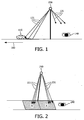
- Based on the experiments conducted by the inventor, two conclusions have been drawn. The first one is that, for the visibility of object, the main contributor is the light beam opposite to the observer rather than the light beam towards the observer. To be specific, referring to
FIG. 1 , the car 110 (i.e., object) is moving along the direction denoted byarrow 160, and to ensure the visibility of thecar 110, thelight beam 121 opposite to theobserver 140 outweigh thelight beam 131 towards theobserver 140. - The second one is that, for illuminating the area of the road surface, using the light beam towards the observer can save much more energy than using the light beam opposite to the observer. To be specific, referring to
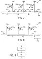
FIG. 2 , the light beam 221 (i.e., the light beam opposite to the observer 240) of thelighting device 250 is used to illuminate the area B of the road surface, and the light beam 231 (i.e., the light beam towards the observer 240) is used to illuminate the area A of the road surface. The experiments conducted by the inventor show that the perceived luminance of area A is 3 times higher than that of area B byobserver 240; therefore, to achieve the same lighting level on the road surface, illuminating the area A could save energy about three times than illuminating the area B. - Typically, in rush time, the traffic flow is heavy and thus the visibility of the forward objects is quite important to ensure road traffic safety; in non rush time, the traffic flow is relatively low and thus visual task for drivers is much easier. Based on these concerns and the above two conclusions drawn by the inventor, it would be advantageous to achieve a lighting device which can increase the visibility of objects in rush time to ensure the traffic safety and/or save energy in non-rush time while keeping the same lighting level as normal.
- In one aspect, one embodiment of the invention provides a lighting device. The lighting device for road lighting comprises a lighting module; and a control module coupled to the lighting module, and configured to control the lighting module to radiate a first light beam towards a first direction to generate a first lighting pattern on the road surface, when a first predetermined condition is satisfied, and to control the lighting module to radiate a second light beam towards a second direction to generate a second lighting pattern on the road surface, when a second predetermined condition is satisfied, wherein the first direction is oriented to go along the traffic direction and the second direction is oriented to go opposite the traffic direction.
- Advantageously, the first predetermined condition comprises any one or more of:
- the current traffic flow of the road surface being within a first flow range;
- the current time being within a first time range;
- a first trigger signal being received;
- the current traffic flow of the road surface being within a second flow range;
- the current time being within a second time range;
- a second trigger signal being received.
- The lighting device of the present invention could generate the first light beam towards the first direction that goes along the traffic direction, when the first predetermined condition is satisfied, and generate the second light beam towards the second direction that goes opposite the traffic direction, when the second predetermined condition is satisfied. For example, when the current traffic flow is within the first flow range (e.g., in rush time), the lighting device is controlled to generate the first light beam towards the first direction. As the first direction is oriented to go along the traffic direction, almost all the light beam of the lighting device is directed at the rear of the forward objects and thus the visibility of the forward objects is increased. Therefore, compared to the conventional lighting device with the same power, the lighting device of the present invention could increase the visibility of the forward objects on the road surface while reducing glaring, and thus ensure the traffic safety better.
- When the current traffic flow is within the second flow range (e.g., in non rush time), the lighting device is controlled to generate the second light beam towards the second direction. As the second direction is oriented to go opposite the traffic direction, the luminance on the road surface illuminated by the lighting device is much higher than that of the conventional lighting device with the same power. In this regard, to achieve the same lighting level as normal, the power of the second light beam can be reduced, and thereby the energy saving of the lighting device is achieved.
- In another aspect, one embodiment of the invention provides a lighting apparatus. The lighting apparatus comprises a support mounted on the road surface and the lighting device according to the first aspect of this invention mounted on the support and oriented relative to the road surface such that the lighting apparatus radiates the first light beam towards the first direction to generate the first lighting pattern on the road surface when the first predetermined condition is satisfied, and radiate the second light beam towards the second direction to generate the second lighting pattern on the road surface when the second predetermined condition is satisfied.
- In still another aspect, one embodiment of the invention provides a lighting system, comprises a plurality of lighting apparatuses according to the second aspect of this invention, wherein the support of each of the plurality of lighting apparatuses is configured to be mounted on the road surface and spaced apart one another such that the first lighting patterns of the plurality of lighting apparatuses cover the whole road surface, and the second lighting patterns of the plurality of lighting apparatuses cover the whole road surface.
- In still another aspect, one embodiment of the invention provides a method of controlling the lighting device according to claim 1 to generate an illuminance on a road surface, the method comprising the steps of:
- determining whether a first predetermined condition is satisfied or a second predetermined condition is satisfied;
- controlling the lighting device to radiate a first light beam towards a first direction to generate a first lighting pattern on the road surface when the first predetermined condition is satisfied, and controlling the lighting device to radiate a second light beam towards a second direction to generate a second lighting pattern on the road surface when the second predetermined condition is satisfied.
- The above and other objects and features of the present invention will become more apparent from the following detailed description considered in connection with the accompanying drawings, in which:
-
FIG. 1 shows a side view of an application scenario to which a conventional lighting device is applied; -
FIG. 2 shows a perspective view of a lighting pattern generated by a conventional lighting device; -
FIG. 3 shows a side view of an application scenario to which a conventional lighting system is applied; -
FIG. 4 shows a block diagram of the lighting device according to one embodiment of the present invention; -
FIG. 5 shows a perspective view of a lighting module according to one embodiment of the invention; -
FIG. 6 shows a perspective view of a lighting module according to another embodiment of the invention; -
FIG. 7 shows a side view of an application scenario to which a lighting system according to one embodiment of the invention is applied, where the first predetermined condition is satisfied; -
FIG. 8 shows a side view of an application scenario to which a lighting system according to one embodiment of the invention is applied, where the second predetermined condition is satisfied; -
FIG. 9 shows a flow chart of a method of controlling a lighting device according to the present invention; - Reference will now be made to embodiments of the invention, one or more examples of which are illustrated in the figures. The embodiments are provided by way of explanation of the invention, and are not meant as a limitation of the invention. For example, features illustrated or described as part of one embodiment may be used with another embodiment to yield still a further embodiment. It is intended that the invention encompass these and other modifications and variations as come within the scope and spirit of the invention.
-
FIG. 3 shows a side view of an application scenario to which a conventional lighting system is applied. For illustrative purposes only, threeconventional lighting devices FIG. 3 . - Referring to
FIG. 3 , each of the threeconventional lighting devices support lighting device - The lighting device, the lighting apparatus and the lighting system of embodiments of the invention are the improvement of the conventional lighting device, the conventional light apparatus and the conventional lighting system.
-
FIG. 4 shows a block diagram of the lighting device according to one embodiment of the present invention. Thelighting device 450 for road lighting comprises alighting module 451 and acontrol module 455 coupled to thelighting module 451. Thecontrol module 455 is configured to control thelighting module 451 to radiate a first light beam towards a first direction to generate a first lighting pattern on the road surface, when a first predetermined condition is satisfied, and to control thelighting module 451 to radiate a second light beam towards a second direction to generate a second lighting pattern on the road surface, when a second predetermined condition is satisfied. The first direction is oriented to go along the traffic direction and the second direction is oriented to go opposite the traffic direction. - The first predetermined condition and the second predetermined condition can be implemented in various scenarios. In one example, the first predetermined condition may be the current traffic flow of the road surface being within the first flow range, and the second predetermined condition may be the current traffic flow of the road surface being within the second flow range. In this case, the
control module 455 may comprise a sensor and a processor coupled to the sensor. The sensor measures the current traffic flow and provides the outcome to the processor. The processor receives the outcome from the sensor and determines whether the current traffic flow is within the first flow range or within the second flow range based on the received outcome. If the outcome indicates that the current traffic flow is within the first flow range, for example, from 300pcu/min to 2000pcu/min, then the processor controls thelighting module 451 to radiate the first light beam towards the first direction. If the outcome indicates that the current traffic flow is within the second flow range, for example, from 0 to 300pcu/min, then the processor controls thelighting module 451 to radiate the second light beam towards the second direction. Advantageously, the sensor measures the current traffic flow periodically, for example, every 5 minutes. - In another example, the first predetermined condition may be the current time being within the first time range, and the second predetermined condition may be the current time being within the second time range. In this case, the
control module 455 may comprise a timer and a processor coupled to the timer. The processor obtains the time value from the timer and determines whether the current time is within the first time range or within the second time range. If the time value indicates the current time is within the first time range, for example within the time range from 18:00 to 21:00, then the processor controls thelighting module 451 to radiate the first light beam towards the first direction. If the time value indicated the current time is within the second time range, for example within the time range from 21:00 to 5:00, then the processor controls thelighting module 451 to radiate the second light beam towards the second direction. - In still another example, the first predetermined condition may be a first trigger signal being received, and the second predetermined condition may be a second trigger signal being received. In this case, the first and second trigger signals may be generated by a manual switch and then provided to the
control module 455 of thelighting device 450. - The lighting module of the invention can be achieved by various approaches. In one example, the
lighting module 551 may comprise twolighting units FIG 5 . When the first predetermined condition is satisfied, thefirst lighting unit 552 is controlled to radiate the first light beam towards the first direction; when the second predetermined condition is satisfied, thesecond lighting unit 553 is controlled to radiate the second light beam towards the second direction. - In another example, the
lighting module 651 may comprise onelighting unit 652 and adriving unit 654, as shown inFIG 6 . When the first predetermined condition is satisfied, the drivingunit 654 is controlled to adjust the orientation of thelighting module 651 to radiate the first light beam towards the first direction; when the second predetermined condition is satisfied, the drivingunit 654 is controlled to adjust the orientation of thelighting module 651 to radiate the second light beam towards the second direction. The driving unit may be a motor, for example. - The
lighting device 450 ofFIG. 4 may be applicable to any suitable lighting scenario. For example, thelighting device 450 may be mounted on a support to constitute a lighting apparatus. A plurality of lighting apparatuses may be mounted on the road surface and spaced apart one another to form a road lighting system, as shown inFIG 7 and FIG 8 . - Hereinafter, the
road lighting system 700 of one embodiment of the invention will be described in detail using the current time being within the first time range as an example of the first predetermined condition and the current time being within the second time range as an example of the second predetermined condition. - When the current time is within the first time range, for example within the time range from 18:00 to 21:00, which means the current traffic flow is heavy, then all the
light devices lighting system 700 are controlled to radiate thefirst light beams traffic direction 760, as shown inFIG. 7 . Since almost all light beams of thelighting devices car 717, thelight beam 720c from thelighting device 750c is directed at the rear of the forward car 716 and thus the visibility of the forward car 716 is increased. - Therefore, compared to the conventional lighting system with the same power illustrated in
FIG 3 , thelighting system 700 of the invention could increase, for drivers behind, the visibility of forward cars while reducing glaring, and thus ensure the traffic safety better. - When the current time is within the second time range, for example within the time range from 21:00 to 5:00, which means the current traffic flow is low, then all the
light devices lighting system 700 are controlled to radiate thesecond light beams traffic direction 760, as shown inFIG 8 . Since almost all light beams of thelighting devices traffic direction 760, in order to generate the same lighting level, thelighting devices lighting system 700 can consume less energy than that of the conventional lighting system ofFIG. 3 . Using the configuration of thelighting module 551 ofFIG 5 as an example, the power of thesecond lighting unit 553 can be set to be smaller than that of thefirst lighting unit 552. In this way, the energy saving of thelighting system 700 is achieved. - Advantageously, the
lighting devices lighting system 700 are oriented with respect to the road surface such that the lighting patterns A1, A2 and A3 on the road surface are consecutive to-each other and the lighting pattern B1, B2 and B3 on the road surface are consecutive to each other, which means the lighting patterns of thelighting system 700 cover the whole road surface. In this way, a uniform illuminance can be achieved on the road surface. -
FIG. 9 shows a flow chart of a method of controlling a lighting device according to the present invention. - The method of
FIG 9 comprisesStep 910 of determining whether a first predetermined condition is satisfied or a second predetermined condition is satisfied; and Step 920 of controlling the lighting device to radiate a first light beam towards a first direction to generate a first lighting pattern on the road surface when the first predetermined condition is satisfied, and controlling the lighting device to radiate a second light beam towards a second direction to generate a second lighting pattern on the road surface when the second predetermined condition is satisfied. - The first predetermined condition may comprise any one or more of:
- the current traffic flow of the road surface being within a first flow range;
- the current time being within a first time range;
- a first trigger signal being received.
- The second predetermined condition comprises any one or more of:
- the current traffic flow of the road surface being within a second flow range;
- the current time being within a second time range;
- a second trigger signal being received.
- In one example, when the first predetermined condition is the current traffic flow of the road surface being within the first flow range, and the second predetermined condition is the current traffic flow of the road surface being within the second flow range,
Step 910 may comprise the step of: determining whether the current traffic flow is within the first flow range or within the second flow range; andStep 920 may comprise the step of: controlling the lighting device to radiate the first light beam towards the first direction when the current traffic flow is within the first flow range, and controlling the lighting device to radiate the second light beam towards the second direction when the current traffic flow is within the second flow range. - In another embodiment, when the first predetermined condition is the current time being within the first time range, and the second predetermined condition is the current time being within the second time range,
Step 910 may comprise the step of: determining whether the current time is within the first time range or within the second time range; andStep 920 may comprise the step of: controlling the lighting device to radiate the first light beam towards the first direction when the current time is within the first time range, and controlling the lighting device to radiate the second light beam towards the second direction when the current time is within the second time range. - It should be noted that the above described embodiments are given for describing rather than limiting the invention, and it is to be understood that modifications and variations may be resorted to without departing from the scope of the invention as those skilled in the art readily understand. Such modifications and variations are considered to be within the scope of the invention and the appended claims. The protection scope of the invention is defined by the accompanying claims. In addition, any of the reference numerals in the claims should not be interpreted as a limitation to the claims. Use of the verb "comprise" and its conjugations does not exclude the presence of elements or steps other than those stated in a claim. The indefinite article "a" or "an" preceding an element or step does not exclude the presence of a plurality of such elements or steps.
Claims (13)
- A lighting device for road lighting, the lighting device comprising:a lighting module; anda control module coupled to the lighting module, and configured to control the lighting module to radiate a first light beam towards a first direction to generate a first lighting pattern on the road surface, when a first predetermined condition is satisfied, and to control the lighting module to radiate a second light beam towards a second direction to generate a second lighting pattern on the road surface, when a second predetermined condition is satisfied;wherein the first direction is oriented to go along the traffic direction and the second direction is oriented to go opposite the traffic direction.
- The lighting device of claim 1, wherein the first predetermined condition comprises any one or more of:- the current traffic flow of the road surface being within a first flow range;- the current time being within a first time range;- a first trigger signal being received;wherein the second predetermined condition comprises any one or more of:- the current traffic flow of the road surface being within a second flow range;- the current time being within a second time range;- a second trigger signal being received.
- The lighting device of claim 2, wherein- the first predetermined condition is that the current traffic flow of the road surface is within the first flow range, and- the second predetermined condition is that the current traffic flow of the road surface is within the second flow range,and wherein the control module comprises:a sensor configured to measure the current traffic flow; anda processor coupled to the sensor and configured to control the lighting module to radiate the first light beam towards the first direction when the current traffic flow measured by the sensor is within the first flow range, and to control the lighting module to radiate the second light beam towards the second direction when the current traffic flow measured by the sensor is within the second flow range.
- The lighting device of claim 2, wherein- the first predetermined condition is that the current time is within the first time range, and- the second predetermined condition is that the current time is within the second time range,and wherein the control module comprises:a timer; anda processor coupled to the timer, and configured to control the lighting module to radiate the first light beam towards the first direction when the time value of the timer indicates the current time is within the first time range, and to control the lighting module to radiate the second light beam towards the second direction when the time value of the timer indicates the current time is within the second time range.
- The lighting device of claim 1, wherein the lighting module comprises a first lighting unit and a second lighting unit, wherein the control unit is configured to control the first lighting unit to radiate the first light beam towards the first direction when the first predetermined condition is satisfied, and to control the second lighting unit to radiate the second light beam towards the second direction when the second predetermined condition is satisfied.
- The lighting device of claim 5, wherein the power of the second lighting unit is smaller than the power of the first lighting unit.
- The lighting device of claim 1, wherein the lighting module comprises a lighting unit and a driving unit coupled to the lighting unit, wherein the control unit is configured to control the driving unit to adjust the orientation of the lighting unit to radiate the first light beam towards the first direction when the first predetermined condition is satisfied, and to control the driving unit to adjust the orientation of the lighting unit to radiate the second light beam towards the second direction when the second predetermined condition is satisfied
- A lighting apparatus, comprising:a support mounted on the road surface;the lighting device according to any one of claims 1 to 7 mounted on the support and oriented relative to the road surface such that the lighting apparatus radiates the first light beam towards the first direction to generate the first lighting pattern on the road surface when the first predetermined condition is satisfied, and radiate the second light beam towards the second direction to generate the second lighting pattern on the road surface when the second predetermined condition is satisfied.
- A lighting system, comprising:a plurality of lighting apparatuses according to claim 8, wherein the support of each of the plurality of lighting apparatuses is configured to be mounted on the road surface and spaced apart one another such that the first lighting patterns of the plurality of lighting apparatuses cover the whole road surface, and the second lighting patterns of the plurality of lighting apparatuses cover the whole road surface.
- A method of controlling the lighting device according to claim 1 to generate an illuminance on a road surface, the method comprising the steps of:- determining whether a first predetermined condition is satisfied or a second predetermined condition is satisfied;- controlling the lighting device to radiate a first light beam towards a first direction to generate a first lighting pattern on the road surface when the first predetermined condition is satisfied, and controlling the lighting device to radiate a second light beam towards a second direction to generate a second lighting pattern on the road surface when the second predetermined condition is satisfied.
- The method of claim 10, wherein the first predetermined condition comprises any one or more of:- the current traffic flow of the road surface being within a first flow range;- the current time being within a first time range;- a first trigger signal being received;wherein the second predetermined condition comprises any one or more of:- the current traffic flow of the road surface being within a second flow range;- the current time being within a second time range;- a second trigger signal being received.
- The method of claim 10, wherein when the first predetermined condition is the current traffc flow of the road surface being within the first flow range, and the second predetermined condition is the current traffic flow of the road surface being within the second flow range, the step of determining comprises:- determining whether the current traffic flow is within the first flow range or within the second flow range;wherein the step of controlling comprises:- controlling the lighting device to radiate the first light beam towards the first direction when the current traffic flow is within the first flow range, and controlling the lighting device to radiate the second light beam towards the second direction when the current traffic flow is within the second flow range.
- The method of claim 10, wherein when the first predetermined condition is the current time being within the first time range, and the second predetermined condition is the current time being within the second time range, the step of determining comprises:- determining whether the current time is within the first time range or within the second time range;wherein the step of controlling comprises:- controlling the lighting device to radiate the first light beam towards the first direction when the current time is within the first time range, and controlling the lighting device to radiate the second light beam towards the second direction when the current time is within the second time range.
Applications Claiming Priority (2)
| Application Number | Priority Date | Filing Date | Title |
|---|---|---|---|
| CN2012078758 | 2012-07-17 | ||
| PCT/IB2013/055506 WO2014013380A1 (en) | 2012-07-17 | 2013-07-05 | A lighting device, a method of controlling the same, for selectively emitting light along or against traffic direction |
Publications (2)
| Publication Number | Publication Date |
|---|---|
| EP2839718A1 EP2839718A1 (en) | 2015-02-25 |
| EP2839718B1 true EP2839718B1 (en) | 2016-04-27 |
Family
ID=49170764
Family Applications (1)
| Application Number | Title | Priority Date | Filing Date |
|---|---|---|---|
| EP13762575.2A Active EP2839718B1 (en) | 2012-07-17 | 2013-07-05 | A lighting device, a method of controlling the same, for selectively emitting light along or against traffic direction |
Country Status (5)
| Country | Link |
|---|---|
| US (1) | US9310055B2 (en) |
| EP (1) | EP2839718B1 (en) |
| JP (1) | JP6133419B2 (en) |
| ES (1) | ES2581907T3 (en) |
| WO (1) | WO2014013380A1 (en) |
Families Citing this family (4)
| Publication number | Priority date | Publication date | Assignee | Title |
|---|---|---|---|---|
| DE102014015464A1 (en) * | 2014-10-20 | 2016-04-21 | Bartenbach Holding Gmbh | street lamp |
| EA033035B1 (en) * | 2017-08-16 | 2019-08-30 | Овсеп Гагикович Григорян | Method for control of luminous flux from street lights installed separately and/or in a row at motor roads and/or pedestrian crossings and having controllable led lamps |
| ES2992984T3 (en) | 2018-03-26 | 2024-12-20 | Basf Se | Novel hyperbranched polyesters and their use as wax inhibitor, as pour point depressant, as lubricant or in lubricating oils |
| CN116887488B (en) * | 2023-09-07 | 2023-12-12 | 中建照明有限公司 | Traffic lighting control system for urban road and control method thereof |
Family Cites Families (21)
| Publication number | Priority date | Publication date | Assignee | Title |
|---|---|---|---|---|
| JPS61138404A (en) | 1984-12-07 | 1986-06-25 | 松下電器産業株式会社 | Tunnel lighting apparatus |
| JPH05120904A (en) | 1991-10-25 | 1993-05-18 | Nissan Motor Co Ltd | Road lighting device |
| DE4431750A1 (en) | 1994-09-06 | 1996-03-07 | Siemens Ag | Locally fixed lighting installation for public roads with number of lamp units |
| JP3915385B2 (en) | 2000-08-21 | 2007-05-16 | 松下電工株式会社 | Road lighting method and line-of-sight type lighting device |
| JP4013737B2 (en) * | 2002-11-11 | 2007-11-28 | 松下電工株式会社 | Road lighting equipment |
| JP2006525591A (en) | 2003-05-07 | 2006-11-09 | コーニンクレッカ フィリップス エレクトロニクス エヌ ヴィ | Public service system |
| US20070014119A1 (en) * | 2005-07-12 | 2007-01-18 | Burkett Karl A | Variable lighting system for optimizing night visibility |
| JP4651528B2 (en) * | 2005-12-16 | 2011-03-16 | 小糸工業株式会社 | Lighting control device and lighting device |
| JP4651553B2 (en) | 2006-02-08 | 2011-03-16 | 小糸工業株式会社 | Lighting control device and lighting device |
| US20070273500A1 (en) | 2006-05-22 | 2007-11-29 | Chih Hung Chiu | Radio-linked streetlamp |
| JP4745184B2 (en) * | 2006-10-03 | 2011-08-10 | スタンレー電気株式会社 | Lighting device |
| JP2008258007A (en) | 2007-04-05 | 2008-10-23 | Matsushita Electric Ind Co Ltd | Street light |
| DE102007061160A1 (en) | 2007-12-17 | 2009-06-25 | Semperlux Aktiengesellschaft - Lichttechnische Werke - | Outdoor light arrangement for illuminating paths and buildings comprises illuminating diodes and units for controlling the light distribution of the diodes so that the light distribution is adapted to different illuminating situations |
| DE202008004790U1 (en) | 2008-04-04 | 2008-07-03 | Semperlux Aktiengesellschaft - Lichttechnische Werke - | Lamp with LED spotlights |
| EP2233826B1 (en) | 2009-03-17 | 2015-12-16 | Thorn Europhane S.A. | Lighting unit and luminaire for road and/or street lighting |
| CA2760380C (en) | 2009-04-28 | 2016-03-22 | Dialight Corporation | Method and apparatus for multi-zoned illumination |
| WO2011037993A2 (en) | 2009-09-25 | 2011-03-31 | Musco Corporation | Apparatus, method, and system for roadway lighting using solid-state light sources |
| RU2009137605A (en) * | 2009-10-12 | 2011-04-20 | Сергей Яковлевич Белогловский (RU) | METHOD OF ORGANIZING ENERGY-SAVING ARTIFICIAL LIGHTING AND INTELLECTUAL DEVICE (OPTIONS) |
| JP5588179B2 (en) * | 2010-01-07 | 2014-09-10 | コイト電工株式会社 | Lighting system |
| JP2011253772A (en) | 2010-06-03 | 2011-12-15 | Panasonic Electric Works Co Ltd | Light-distribution-variable type lighting fixture and road lighting system using the same |
| JP5516214B2 (en) | 2010-08-11 | 2014-06-11 | 岩崎電気株式会社 | Connection structure of lighting equipment |
-
2013
- 2013-07-05 ES ES13762575.2T patent/ES2581907T3/en active Active
- 2013-07-05 US US14/414,223 patent/US9310055B2/en active Active
- 2013-07-05 JP JP2015521110A patent/JP6133419B2/en active Active
- 2013-07-05 EP EP13762575.2A patent/EP2839718B1/en active Active
- 2013-07-05 WO PCT/IB2013/055506 patent/WO2014013380A1/en not_active Ceased
Also Published As
| Publication number | Publication date |
|---|---|
| US9310055B2 (en) | 2016-04-12 |
| JP2015525954A (en) | 2015-09-07 |
| WO2014013380A1 (en) | 2014-01-23 |
| US20150211716A1 (en) | 2015-07-30 |
| EP2839718A1 (en) | 2015-02-25 |
| JP6133419B2 (en) | 2017-05-24 |
| ES2581907T3 (en) | 2016-09-08 |
Similar Documents
| Publication | Publication Date | Title |
|---|---|---|
| US8519624B2 (en) | Roadside-vehicle cooperative illumination system | |
| EP2641780A2 (en) | Sub headlight unit and sub headlight system for use in vehicle that leans into turns, and vehicle that leans into turns, and method for controlling light emission of a sub headlight unit | |
| US20150338045A1 (en) | Vehicle headlight and alert system | |
| CN103608215A (en) | Method and control unit for actuating at least one headlamp of vehicle using traffic density | |
| EP2676872B1 (en) | Sub-headlight unit, headlight unit, headlight system for vehicles that lean into turns, a vehicle that leans into turns and a method for controlling a sub-headlight unit for vehicles that lean into turns | |
| US9586521B2 (en) | Turn signal lamp for vehicle | |
| CN204020699U (en) | The control system of vehicle and vehicle brake lamp | |
| CN103042968A (en) | Automobile lamp control method and automobile lamp control system | |
| US9310055B2 (en) | Lighting device, a method of controlling the same, for selectively emitting light along or against traffic direction | |
| CN201998885U (en) | Vehicle-mounted lighting lamp control system | |
| KR101608217B1 (en) | Lighting system and its operation method | |
| US20170057403A1 (en) | Vehicle lamp system | |
| JP2018024351A (en) | Automated driving system | |
| TWM591483U (en) | Fill-light safety device applicable to curved road | |
| CN102009615B (en) | Overlength vehicle and side marker lamp control method and side marker lamp control system thereof | |
| CN104335684B (en) | A lighting device, a method of controlling the same, for selectively emitting light along or against traffic direction | |
| KR101360672B1 (en) | Apparatus for controlling dimming of head lamp | |
| KR101934752B1 (en) | Vehicle Front Lamp Beam Pattern Control Method and Apparatus | |
| CN204077521U (en) | A kind of bend auxiliary lighting corner lamp | |
| GB2594540A (en) | Traffic signalling apparatus | |
| JP2002063803A (en) | Method of road illumination and eye-guiding illumination device | |
| JP2015020625A (en) | Vehicle rear lighting system | |
| KR102315556B1 (en) | System for controlling turn signal lamps and method for lighting turn signal lamps sequentially | |
| CN108692262A (en) | The lighting device that the range of illumination changes between small range and long range | |
| US20090154181A1 (en) | Vehicle auxiliary lighting system |
Legal Events
| Date | Code | Title | Description |
|---|---|---|---|
| PUAI | Public reference made under article 153(3) epc to a published international application that has entered the european phase |
Free format text: ORIGINAL CODE: 0009012 |
|
| 17P | Request for examination filed |
Effective date: 20141119 |
|
| AK | Designated contracting states |
Kind code of ref document: A1 Designated state(s): AL AT BE BG CH CY CZ DE DK EE ES FI FR GB GR HR HU IE IS IT LI LT LU LV MC MK MT NL NO PL PT RO RS SE SI SK SM TR |
|
| AX | Request for extension of the european patent |
Extension state: BA ME |
|
| DAX | Request for extension of the european patent (deleted) | ||
| GRAP | Despatch of communication of intention to grant a patent |
Free format text: ORIGINAL CODE: EPIDOSNIGR1 |
|
| RIC1 | Information provided on ipc code assigned before grant |
Ipc: F21W 131/103 20060101ALI20151027BHEP Ipc: F21V 14/02 20060101ALI20151027BHEP Ipc: F21S 8/08 20060101ALI20151027BHEP Ipc: H05B 37/02 20060101AFI20151027BHEP |
|
| INTG | Intention to grant announced |
Effective date: 20151120 |
|
| GRAS | Grant fee paid |
Free format text: ORIGINAL CODE: EPIDOSNIGR3 |
|
| GRAA | (expected) grant |
Free format text: ORIGINAL CODE: 0009210 |
|
| AK | Designated contracting states |
Kind code of ref document: B1 Designated state(s): AL AT BE BG CH CY CZ DE DK EE ES FI FR GB GR HR HU IE IS IT LI LT LU LV MC MK MT NL NO PL PT RO RS SE SI SK SM TR |
|
| REG | Reference to a national code |
Ref country code: GB Ref legal event code: FG4D |
|
| REG | Reference to a national code |
Ref country code: CH Ref legal event code: EP |
|
| REG | Reference to a national code |
Ref country code: AT Ref legal event code: REF Ref document number: 796011 Country of ref document: AT Kind code of ref document: T Effective date: 20160515 |
|
| REG | Reference to a national code |
Ref country code: IE Ref legal event code: FG4D |
|
| REG | Reference to a national code |
Ref country code: DE Ref legal event code: R096 Ref document number: 602013007152 Country of ref document: DE |
|
| REG | Reference to a national code |
Ref country code: NL Ref legal event code: FP |
|
| REG | Reference to a national code |
Ref country code: FR Ref legal event code: PLFP Year of fee payment: 4 |
|
| RAP2 | Party data changed (patent owner data changed or rights of a patent transferred) |
Owner name: PHILIPS LIGHTING HOLDING B.V. |
|
| REG | Reference to a national code |
Ref country code: LT Ref legal event code: MG4D |
|
| REG | Reference to a national code |
Ref country code: ES Ref legal event code: FG2A Ref document number: 2581907 Country of ref document: ES Kind code of ref document: T3 Effective date: 20160908 |
|
| REG | Reference to a national code |
Ref country code: AT Ref legal event code: MK05 Ref document number: 796011 Country of ref document: AT Kind code of ref document: T Effective date: 20160427 |
|
| PG25 | Lapsed in a contracting state [announced via postgrant information from national office to epo] |
Ref country code: PL Free format text: LAPSE BECAUSE OF FAILURE TO SUBMIT A TRANSLATION OF THE DESCRIPTION OR TO PAY THE FEE WITHIN THE PRESCRIBED TIME-LIMIT Effective date: 20160427 Ref country code: FI Free format text: LAPSE BECAUSE OF FAILURE TO SUBMIT A TRANSLATION OF THE DESCRIPTION OR TO PAY THE FEE WITHIN THE PRESCRIBED TIME-LIMIT Effective date: 20160427 Ref country code: LT Free format text: LAPSE BECAUSE OF FAILURE TO SUBMIT A TRANSLATION OF THE DESCRIPTION OR TO PAY THE FEE WITHIN THE PRESCRIBED TIME-LIMIT Effective date: 20160427 Ref country code: NO Free format text: LAPSE BECAUSE OF FAILURE TO SUBMIT A TRANSLATION OF THE DESCRIPTION OR TO PAY THE FEE WITHIN THE PRESCRIBED TIME-LIMIT Effective date: 20160727 |
|
| REG | Reference to a national code |
Ref country code: GB Ref legal event code: 732E Free format text: REGISTERED BETWEEN 20161006 AND 20161012 |
|
| PG25 | Lapsed in a contracting state [announced via postgrant information from national office to epo] |
Ref country code: GR Free format text: LAPSE BECAUSE OF FAILURE TO SUBMIT A TRANSLATION OF THE DESCRIPTION OR TO PAY THE FEE WITHIN THE PRESCRIBED TIME-LIMIT Effective date: 20160728 Ref country code: SE Free format text: LAPSE BECAUSE OF FAILURE TO SUBMIT A TRANSLATION OF THE DESCRIPTION OR TO PAY THE FEE WITHIN THE PRESCRIBED TIME-LIMIT Effective date: 20160427 Ref country code: LV Free format text: LAPSE BECAUSE OF FAILURE TO SUBMIT A TRANSLATION OF THE DESCRIPTION OR TO PAY THE FEE WITHIN THE PRESCRIBED TIME-LIMIT Effective date: 20160427 Ref country code: AT Free format text: LAPSE BECAUSE OF FAILURE TO SUBMIT A TRANSLATION OF THE DESCRIPTION OR TO PAY THE FEE WITHIN THE PRESCRIBED TIME-LIMIT Effective date: 20160427 Ref country code: RS Free format text: LAPSE BECAUSE OF FAILURE TO SUBMIT A TRANSLATION OF THE DESCRIPTION OR TO PAY THE FEE WITHIN THE PRESCRIBED TIME-LIMIT Effective date: 20160427 Ref country code: PT Free format text: LAPSE BECAUSE OF FAILURE TO SUBMIT A TRANSLATION OF THE DESCRIPTION OR TO PAY THE FEE WITHIN THE PRESCRIBED TIME-LIMIT Effective date: 20160829 Ref country code: HR Free format text: LAPSE BECAUSE OF FAILURE TO SUBMIT A TRANSLATION OF THE DESCRIPTION OR TO PAY THE FEE WITHIN THE PRESCRIBED TIME-LIMIT Effective date: 20160427 |
|
| PG25 | Lapsed in a contracting state [announced via postgrant information from national office to epo] |
Ref country code: BE Free format text: LAPSE BECAUSE OF FAILURE TO SUBMIT A TRANSLATION OF THE DESCRIPTION OR TO PAY THE FEE WITHIN THE PRESCRIBED TIME-LIMIT Effective date: 20160427 |
|
| REG | Reference to a national code |
Ref country code: DE Ref legal event code: R097 Ref document number: 602013007152 Country of ref document: DE |
|
| PG25 | Lapsed in a contracting state [announced via postgrant information from national office to epo] |
Ref country code: SK Free format text: LAPSE BECAUSE OF FAILURE TO SUBMIT A TRANSLATION OF THE DESCRIPTION OR TO PAY THE FEE WITHIN THE PRESCRIBED TIME-LIMIT Effective date: 20160427 Ref country code: CZ Free format text: LAPSE BECAUSE OF FAILURE TO SUBMIT A TRANSLATION OF THE DESCRIPTION OR TO PAY THE FEE WITHIN THE PRESCRIBED TIME-LIMIT Effective date: 20160427 Ref country code: RO Free format text: LAPSE BECAUSE OF FAILURE TO SUBMIT A TRANSLATION OF THE DESCRIPTION OR TO PAY THE FEE WITHIN THE PRESCRIBED TIME-LIMIT Effective date: 20160427 Ref country code: EE Free format text: LAPSE BECAUSE OF FAILURE TO SUBMIT A TRANSLATION OF THE DESCRIPTION OR TO PAY THE FEE WITHIN THE PRESCRIBED TIME-LIMIT Effective date: 20160427 Ref country code: DK Free format text: LAPSE BECAUSE OF FAILURE TO SUBMIT A TRANSLATION OF THE DESCRIPTION OR TO PAY THE FEE WITHIN THE PRESCRIBED TIME-LIMIT Effective date: 20160427 |
|
| REG | Reference to a national code |
Ref country code: DE Ref legal event code: R081 Ref document number: 602013007152 Country of ref document: DE Owner name: SIGNIFY HOLDING B.V., NL Free format text: FORMER OWNER: KONINKLIJKE PHILIPS N.V., EINDHOVEN, NL Ref country code: DE Ref legal event code: R082 Ref document number: 602013007152 Country of ref document: DE Representative=s name: MEISSNER BOLTE PATENTANWAELTE RECHTSANWAELTE P, DE Ref country code: DE Ref legal event code: R081 Ref document number: 602013007152 Country of ref document: DE Owner name: PHILIPS LIGHTING HOLDING B.V., NL Free format text: FORMER OWNER: KONINKLIJKE PHILIPS N.V., EINDHOVEN, NL |
|
| PG25 | Lapsed in a contracting state [announced via postgrant information from national office to epo] |
Ref country code: SM Free format text: LAPSE BECAUSE OF FAILURE TO SUBMIT A TRANSLATION OF THE DESCRIPTION OR TO PAY THE FEE WITHIN THE PRESCRIBED TIME-LIMIT Effective date: 20160427 |
|
| REG | Reference to a national code |
Ref country code: CH Ref legal event code: PL |
|
| PLBE | No opposition filed within time limit |
Free format text: ORIGINAL CODE: 0009261 |
|
| STAA | Information on the status of an ep patent application or granted ep patent |
Free format text: STATUS: NO OPPOSITION FILED WITHIN TIME LIMIT |
|
| PG25 | Lapsed in a contracting state [announced via postgrant information from national office to epo] |
Ref country code: MC Free format text: LAPSE BECAUSE OF FAILURE TO SUBMIT A TRANSLATION OF THE DESCRIPTION OR TO PAY THE FEE WITHIN THE PRESCRIBED TIME-LIMIT Effective date: 20160427 |
|
| 26N | No opposition filed |
Effective date: 20170130 |
|
| REG | Reference to a national code |
Ref country code: NL Ref legal event code: PD Owner name: PHILIPS LIGHTING HOLDING B.V.; NL Free format text: DETAILS ASSIGNMENT: CHANGE OF OWNER(S), ASSIGNMENT; FORMER OWNER NAME: KONINKLIJKE PHILIPS N.V. Effective date: 20170309 |
|
| PG25 | Lapsed in a contracting state [announced via postgrant information from national office to epo] |
Ref country code: LI Free format text: LAPSE BECAUSE OF NON-PAYMENT OF DUE FEES Effective date: 20160731 Ref country code: CH Free format text: LAPSE BECAUSE OF NON-PAYMENT OF DUE FEES Effective date: 20160731 |
|
| REG | Reference to a national code |
Ref country code: IE Ref legal event code: MM4A |
|
| PG25 | Lapsed in a contracting state [announced via postgrant information from national office to epo] |
Ref country code: SI Free format text: LAPSE BECAUSE OF FAILURE TO SUBMIT A TRANSLATION OF THE DESCRIPTION OR TO PAY THE FEE WITHIN THE PRESCRIBED TIME-LIMIT Effective date: 20160427 |
|
| REG | Reference to a national code |
Ref country code: FR Ref legal event code: PLFP Year of fee payment: 5 |
|
| PG25 | Lapsed in a contracting state [announced via postgrant information from national office to epo] |
Ref country code: IE Free format text: LAPSE BECAUSE OF NON-PAYMENT OF DUE FEES Effective date: 20160705 |
|
| PG25 | Lapsed in a contracting state [announced via postgrant information from national office to epo] |
Ref country code: LU Free format text: LAPSE BECAUSE OF NON-PAYMENT OF DUE FEES Effective date: 20160705 |
|
| PG25 | Lapsed in a contracting state [announced via postgrant information from national office to epo] |
Ref country code: HU Free format text: LAPSE BECAUSE OF FAILURE TO SUBMIT A TRANSLATION OF THE DESCRIPTION OR TO PAY THE FEE WITHIN THE PRESCRIBED TIME-LIMIT; INVALID AB INITIO Effective date: 20130705 |
|
| PG25 | Lapsed in a contracting state [announced via postgrant information from national office to epo] |
Ref country code: IS Free format text: LAPSE BECAUSE OF FAILURE TO SUBMIT A TRANSLATION OF THE DESCRIPTION OR TO PAY THE FEE WITHIN THE PRESCRIBED TIME-LIMIT Effective date: 20160427 Ref country code: CY Free format text: LAPSE BECAUSE OF FAILURE TO SUBMIT A TRANSLATION OF THE DESCRIPTION OR TO PAY THE FEE WITHIN THE PRESCRIBED TIME-LIMIT Effective date: 20160427 Ref country code: MK Free format text: LAPSE BECAUSE OF FAILURE TO SUBMIT A TRANSLATION OF THE DESCRIPTION OR TO PAY THE FEE WITHIN THE PRESCRIBED TIME-LIMIT Effective date: 20160427 Ref country code: MT Free format text: LAPSE BECAUSE OF NON-PAYMENT OF DUE FEES Effective date: 20160731 |
|
| REG | Reference to a national code |
Ref country code: FR Ref legal event code: PLFP Year of fee payment: 6 |
|
| PG25 | Lapsed in a contracting state [announced via postgrant information from national office to epo] |
Ref country code: BG Free format text: LAPSE BECAUSE OF FAILURE TO SUBMIT A TRANSLATION OF THE DESCRIPTION OR TO PAY THE FEE WITHIN THE PRESCRIBED TIME-LIMIT Effective date: 20160427 |
|
| PG25 | Lapsed in a contracting state [announced via postgrant information from national office to epo] |
Ref country code: TR Free format text: LAPSE BECAUSE OF FAILURE TO SUBMIT A TRANSLATION OF THE DESCRIPTION OR TO PAY THE FEE WITHIN THE PRESCRIBED TIME-LIMIT Effective date: 20160427 Ref country code: AL Free format text: LAPSE BECAUSE OF FAILURE TO SUBMIT A TRANSLATION OF THE DESCRIPTION OR TO PAY THE FEE WITHIN THE PRESCRIBED TIME-LIMIT Effective date: 20160427 |
|
| REG | Reference to a national code |
Ref country code: ES Ref legal event code: PC2A Owner name: PHILIPS LIGHTING HOLDING B.V. Effective date: 20181221 |
|
| REG | Reference to a national code |
Ref country code: NL Ref legal event code: HC Owner name: SIGNIFY HOLDING B.V.; NL Free format text: DETAILS ASSIGNMENT: CHANGE OF OWNER(S), CHANGE OF OWNER(S) NAME; FORMER OWNER NAME: PHILIPS LIGHTING HOLDING B.V. Effective date: 20200304 |
|
| REG | Reference to a national code |
Ref country code: ES Ref legal event code: PC2A Owner name: SIGNIFY HOLDING B.V. Effective date: 20201015 |
|
| REG | Reference to a national code |
Ref country code: DE Ref legal event code: R082 Ref document number: 602013007152 Country of ref document: DE Representative=s name: MEISSNER BOLTE PATENTANWAELTE RECHTSANWAELTE P, DE Ref country code: DE Ref legal event code: R081 Ref document number: 602013007152 Country of ref document: DE Owner name: SIGNIFY HOLDING B.V., NL Free format text: FORMER OWNER: PHILIPS LIGHTING HOLDING B.V., EINDHOVEN, NL |
|
| P01 | Opt-out of the competence of the unified patent court (upc) registered |
Effective date: 20230421 |
|
| PGFP | Annual fee paid to national office [announced via postgrant information from national office to epo] |
Ref country code: NL Payment date: 20250724 Year of fee payment: 13 |
|
| PGFP | Annual fee paid to national office [announced via postgrant information from national office to epo] |
Ref country code: ES Payment date: 20250812 Year of fee payment: 13 |
|
| PGFP | Annual fee paid to national office [announced via postgrant information from national office to epo] |
Ref country code: DE Payment date: 20250926 Year of fee payment: 13 |
|
| PGFP | Annual fee paid to national office [announced via postgrant information from national office to epo] |
Ref country code: IT Payment date: 20250721 Year of fee payment: 13 |
|
| PGFP | Annual fee paid to national office [announced via postgrant information from national office to epo] |
Ref country code: GB Payment date: 20250722 Year of fee payment: 13 |
|
| PGFP | Annual fee paid to national office [announced via postgrant information from national office to epo] |
Ref country code: FR Payment date: 20250725 Year of fee payment: 13 |