EP2839228B1 - Cooling device with holding protrusion and method of producing it - Google Patents
Cooling device with holding protrusion and method of producing it Download PDFInfo
- Publication number
- EP2839228B1 EP2839228B1 EP13716297.0A EP13716297A EP2839228B1 EP 2839228 B1 EP2839228 B1 EP 2839228B1 EP 13716297 A EP13716297 A EP 13716297A EP 2839228 B1 EP2839228 B1 EP 2839228B1
- Authority
- EP
- European Patent Office
- Prior art keywords
- holding protrusion
- cooling device
- housing
- holding
- lateral wall
- Prior art date
- Legal status (The legal status is an assumption and is not a legal conclusion. Google has not performed a legal analysis and makes no representation as to the accuracy of the status listed.)
- Not-in-force
Links
- 238000001816 cooling Methods 0.000 title claims description 26
- 238000000034 method Methods 0.000 title claims description 3
- 238000004519 manufacturing process Methods 0.000 claims description 7
- 229920003023 plastic Polymers 0.000 claims description 6
- 239000004033 plastic Substances 0.000 claims description 6
- 238000003780 insertion Methods 0.000 claims description 3
- 230000037431 insertion Effects 0.000 claims description 3
- 238000000465 moulding Methods 0.000 claims description 3
- 229920002635 polyurethane Polymers 0.000 description 10
- 239000004814 polyurethane Substances 0.000 description 10
- 239000000463 material Substances 0.000 description 6
- 238000005266 casting Methods 0.000 description 2
- 230000006835 compression Effects 0.000 description 2
- 238000007906 compression Methods 0.000 description 2
- 238000010276 construction Methods 0.000 description 2
- 230000000712 assembly Effects 0.000 description 1
- 238000000429 assembly Methods 0.000 description 1
- 238000009413 insulation Methods 0.000 description 1
- 238000003856 thermoforming Methods 0.000 description 1
Images
Classifications
-
- B—PERFORMING OPERATIONS; TRANSPORTING
- B29—WORKING OF PLASTICS; WORKING OF SUBSTANCES IN A PLASTIC STATE IN GENERAL
- B29C—SHAPING OR JOINING OF PLASTICS; SHAPING OF MATERIAL IN A PLASTIC STATE, NOT OTHERWISE PROVIDED FOR; AFTER-TREATMENT OF THE SHAPED PRODUCTS, e.g. REPAIRING
- B29C39/00—Shaping by casting, i.e. introducing the moulding material into a mould or between confining surfaces without significant moulding pressure; Apparatus therefor
- B29C39/003—Shaping by casting, i.e. introducing the moulding material into a mould or between confining surfaces without significant moulding pressure; Apparatus therefor characterised by the choice of material
- B29C39/006—Monomers or prepolymers
-
- B—PERFORMING OPERATIONS; TRANSPORTING
- B29—WORKING OF PLASTICS; WORKING OF SUBSTANCES IN A PLASTIC STATE IN GENERAL
- B29C—SHAPING OR JOINING OF PLASTICS; SHAPING OF MATERIAL IN A PLASTIC STATE, NOT OTHERWISE PROVIDED FOR; AFTER-TREATMENT OF THE SHAPED PRODUCTS, e.g. REPAIRING
- B29C39/00—Shaping by casting, i.e. introducing the moulding material into a mould or between confining surfaces without significant moulding pressure; Apparatus therefor
- B29C39/22—Component parts, details or accessories; Auxiliary operations
- B29C39/26—Moulds or cores
-
- F—MECHANICAL ENGINEERING; LIGHTING; HEATING; WEAPONS; BLASTING
- F25—REFRIGERATION OR COOLING; COMBINED HEATING AND REFRIGERATION SYSTEMS; HEAT PUMP SYSTEMS; MANUFACTURE OR STORAGE OF ICE; LIQUEFACTION SOLIDIFICATION OF GASES
- F25D—REFRIGERATORS; COLD ROOMS; ICE-BOXES; COOLING OR FREEZING APPARATUS NOT OTHERWISE PROVIDED FOR
- F25D23/00—General constructional features
- F25D23/06—Walls
- F25D23/065—Details
- F25D23/067—Supporting elements
-
- B—PERFORMING OPERATIONS; TRANSPORTING
- B29—WORKING OF PLASTICS; WORKING OF SUBSTANCES IN A PLASTIC STATE IN GENERAL
- B29K—INDEXING SCHEME ASSOCIATED WITH SUBCLASSES B29B, B29C OR B29D, RELATING TO MOULDING MATERIALS OR TO MATERIALS FOR MOULDS, REINFORCEMENTS, FILLERS OR PREFORMED PARTS, e.g. INSERTS
- B29K2075/00—Use of PU, i.e. polyureas or polyurethanes or derivatives thereof, as moulding material
-
- F—MECHANICAL ENGINEERING; LIGHTING; HEATING; WEAPONS; BLASTING
- F25—REFRIGERATION OR COOLING; COMBINED HEATING AND REFRIGERATION SYSTEMS; HEAT PUMP SYSTEMS; MANUFACTURE OR STORAGE OF ICE; LIQUEFACTION SOLIDIFICATION OF GASES
- F25D—REFRIGERATORS; COLD ROOMS; ICE-BOXES; COOLING OR FREEZING APPARATUS NOT OTHERWISE PROVIDED FOR
- F25D23/00—General constructional features
- F25D23/06—Walls
- F25D23/065—Details
- F25D23/066—Liners
Definitions
- the invention relates to assemblies used in cooling appliances having a thermally insulated body particularly to fix the compartments that are configured on the opposite lateral walls of a housing within a refrigerator body and are in the form of shelves or drawers, and their production method.
- Cooling devices have compartments like shelves or drawers, which are installed at certain intervals in a housing of a thermally insulated body.
- the shelves or drawers are placed by settling on holding protrusions configured in the lateral walls of a housing. Both opposite edges of the shelves or drawers are in contact with the planar surface of the holding protrusions. Thereby the holding protrusions hold the compartments within the housing in a certain position.
- the holding protrusions As there are holding protrusions parallel to each other and configured in a large number, more than one shelf or drawer can be installed at certain intervals in the housing in parallel to each other.
- the holding protrusions is configured integrally in the lateral walls.
- the holding protrusions can be of different forms with each other.
- another holding protrusion in the form of a thin and long protrusion extending backwards is configured.
- the invention is a cooling device comprising a thermally insulated receptacle having two opposite lateral walls; at least one holding extension positioned on the lateral walls in mutually opposite manner, a compartment having a sliding adjusting element seated over the holding extensions at a carrying surface and movable in a transversal direction.
- the cooling device comprises at least one compression extension having a front surface facing a lateral surface of the compartment and extending towards the compartment lateral surface adjacently to the carrying surface so as to be shorter than the carrying extension.
- the patent publication number US5642924 refers to a shelf system configured for a cooling cabin. It is a cooling cabin having a rear wall and lateral walls with multiple shelf supports mounted on each lateral wall. A hanging bracket is mounted on the rear wall, the bracket is adapted in such a manner that it supports an edge of a half shelf bend with multiple different heights.
- Each shelf support comprises a supporting rail having a rear part and a front part separated with a space. The front part prevents the shelf from waggling in the supporting rail.
- the US 2291547 describes a cabinet construction for a refrigerating apparatus.
- This cabinet construction comprises a supporting member connected with a wall of a cabinet to provide a horizontal support for a shelf to support the shelf in sliding relation to a wall and a second support capable of supporting said shelf in either slidable or non-slidable relation to said wall.
- the object of the invention is to reduce in cooling devices the wall thickness of the housing within the body of the cooling device.
- the invention provides a cooling device as claimed in claim 1.
- the groove is in the portion of the backing part close to its end. So the amount of polyurethane material used in thermal insulation, filled in the inner volume of the holding protrusion is reduced. As the amount of polyurethane per unit volume is low, no or few gaps are formed.
- the holding protrusion is in a form similar to a lateral D letter, especially viewed in a horizontal plane orientated parallel to a plane of a compartment. So the compartments in the form of shelves or drawers are supported also by being held at the front part of the lateral walls.
- the edges of the holding protrusion are radiused. So as the amount of polyurethane per unit volume is low because the surface at the radiused edges becomes tight, no or few gaps are formed.
- the grooves configured in the backing part of the holding protrusion are parallel to each other. So through more than one groove parallel to each other the amount of polyurethane filled in the inner volume of the holding protrusion is low.
- the distance between the grooves configured in the backing part of the holding protrusion is equal to each other. So a regular form is obtained.
- the grooves are bounded by S-shaped cross-ties.
- the cross-ties extend in a direction substantially perpendicular to the lateral wall and parallel to each other.
- the cross-ties extend form the lateral wall to the free edge of the D-shaped holding protrusion.
- a holding protrusion device on a specific horizontal insertion plane for a compartment comprises at least two elements, the first holding protrusion and a second holding protrusion, on a lateral wall which are separate parts, and which are positioned with a distance to each other, and consecutively in a row.
- the second holding protrusion is preferred an oblong element, positioned closer to a back wall of the housing than the first holding protrusion.
- the first holding protrusion is preferred short in comparison to the second holding protrusion and is positioned close to a front edge of the housing.
- a cooling device which comprises the process steps of placing a plastic panel over the mold so as to generate the holding protrusion form of the housing, molding the panel and then removing it from the mold coaxially with the groove extension direction.
- a plastic plate with the normally used optimum wall thickness in which the housing and the holding protrusions on the housing are formed a plastic plate with a thinner wall thickness can be used.
- the invention relates to holding protrusions 3 in cooling appliances having a thermally insulated body 1, that are configured on the opposite lateral walls 100 of a housing 10 within a body 1 and are formed with grooves 321 for carrying the compartments 2 in the form of shelves or drawers, and their production method.
- the grooves 321, especially each, are bounded by cross-ties 322, especially S-shaped cross ties 322.
- the cross ties 322 extend in a direction substantially perpendicular to the lateral wall 100 and parallel to each other and extend form the lateral wall 100 to the front edge of the D-shaped protrusion 3.
- a holding protrusion device 5 on a specific horizontal insertion plane for a compartment 2 comprises at least two elements, the first holding protrusion 3 and a holding second protrusion 6, on a lateral wall 100 which are separate parts, and which are positioned with a distance to each other, and consecutively in a row.
- the second protrusion 6 is an oblong element, positioned close to a back wall of the housing 10.
- the first protrusion 3 is short in comparison to the second protrusion 6 and is positioned close to a front edge of the housing 10.
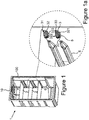
- FIG 1 a perspective front view is given of a cooling device housing 10 having holding protrusions 3 subject of the invention.
- a perspective bottom view is given of the holding protrusions 3 taken from figure 1 that are subject matter of the invention, the backing part 32 of which has a grooved structure with said grooves 321.
- the holding protrusion 3 as can be seen in the figure, is in a form similar to a lateral D letter, especially viewed in a plane parallel to the plane of the compartment 2.
- the planar section 31 is formed in the upper part of the holding protrusion 3 and the backing part 32 is formed in its lower part.
- the planar section 31 is the portion being in contact while carrying the compartment 2.
- the housing 10 of the cooling device is obtained by casting generally polyurethane material in the mold.
- holding protrusions 3 are configured on the lateral walls 100 of the housing 10.
- the grooves 321 are formed in the backing part 32 of the holding protrusion 3.
- the manufacturing mold of the housing 10 is in a protruding 42 form such that it allows obtaining the grooved form of the holding protrusion 3. Therefore the holding protrusion mold 4 is configured and used integrally as a part of the housing 10 mold.
- a recess 41 is configured on the mold 4 to form the holding protrusion 3 and projections 42 parallel to each other are configured to form the grooves 321.
- the grooved structure forms in the backing part 32 of the holding protrusion 3 and the mold 4 is completely and uniformly filled with polyurethane material.
- the housing 10 is removed from the mold, holding protrusions 3 with rigid structure are obtained. Even if the wall thickness of the housing 10 is reduced, the rigidity of the holding protrusions 3 is generated by the grooved form.
- the grooves 321 on the holding protrusions 3 extend parallelly to each other on the backing part 32 and perpendicularly to the lateral wall 100.
- the holding protrusions 3 are configured oppositely at the inner facing sides of the lateral walls 100 of the housing 10. They can be one under the other, parallel to each other and in a large number. Thereby the shelves and drawers can be installed at desired distances in the housing 10. When a shelf or a drawer is placed on the holding protrusion 3, the groove form provides also the resistance of the holding protrusion 3 against load.
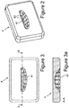
- FIG 2 a perspective view is given of the holding protrusion mold 4 used in more than one of its place as part of the housing 10 mold.
- the portion in which the holding protrusion 3 is formed is in the form of a recess 41 ( figure 2, 3, 3a ).
- the recess 41 resembles a lateral D letter. It has a certain volume. In this volume, the holding protrusion 3 is formed with material casting.
- the holding protrusion 3 has on its both sides ends 33, the corners of which are in rounded form.
- Figure 3a is a view of section A-A taken transversally from the holding protrusion mold 4 given in figure 3 . From here, the depth of the recess 41 formed in the inner wall of the mold 4 can be seen.
- a plastic plate with the normally used optimum wall thickness in which the housing 10 and the holding protrusions 3 on the housing 10 are formed a plastic plate with a thinner wall thickness can be used.
- the end portions 33 of other holding protrusions 3 formed as an oblong protuberance flush with the holding protrusions 3 in a lateral D form configured on the lateral walls 100 of the housing 10 can also be configured in grooved form.
Landscapes
- Engineering & Computer Science (AREA)
- Chemical & Material Sciences (AREA)
- Combustion & Propulsion (AREA)
- Physics & Mathematics (AREA)
- Mechanical Engineering (AREA)
- Thermal Sciences (AREA)
- General Engineering & Computer Science (AREA)
- Moulds For Moulding Plastics Or The Like (AREA)
- Refrigerator Housings (AREA)
Description
- The invention relates to assemblies used in cooling appliances having a thermally insulated body particularly to fix the compartments that are configured on the opposite lateral walls of a housing within a refrigerator body and are in the form of shelves or drawers, and their production method.
- Cooling devices have compartments like shelves or drawers, which are installed at certain intervals in a housing of a thermally insulated body. The shelves or drawers are placed by settling on holding protrusions configured in the lateral walls of a housing. Both opposite edges of the shelves or drawers are in contact with the planar surface of the holding protrusions. Thereby the holding protrusions hold the compartments within the housing in a certain position. As there are holding protrusions parallel to each other and configured in a large number, more than one shelf or drawer can be installed at certain intervals in the housing in parallel to each other. During the manufacturing of the housing of the cooling device with polyurethane and molding with thermoforming process, the holding protrusions is configured integrally in the lateral walls. The holding protrusions can be of different forms with each other. For example, in the front portion of the lateral wall close to the door the holding protrusion in lateral D form and after a gap left between them, another holding protrusion in the form of a thin and long protrusion extending backwards is configured.
- In the patent application number
TR201111817 - The patent publication number
US5642924 refers to a shelf system configured for a cooling cabin. It is a cooling cabin having a rear wall and lateral walls with multiple shelf supports mounted on each lateral wall. A hanging bracket is mounted on the rear wall, the bracket is adapted in such a manner that it supports an edge of a half shelf bend with multiple different heights. Each shelf support comprises a supporting rail having a rear part and a front part separated with a space. The front part prevents the shelf from waggling in the supporting rail. - The
US 2291547 describes a cabinet construction for a refrigerating apparatus. This cabinet construction comprises a supporting member connected with a wall of a cabinet to provide a horizontal support for a shelf to support the shelf in sliding relation to a wall and a second support capable of supporting said shelf in either slidable or non-slidable relation to said wall. - The object of the invention is to reduce in cooling devices the wall thickness of the housing within the body of the cooling device.
- In order to obtain said object, the invention provides a cooling device as claimed in
claim 1. - According to the invention, the groove is in the portion of the backing part close to its end. So the amount of polyurethane material used in thermal insulation, filled in the inner volume of the holding protrusion is reduced. As the amount of polyurethane per unit volume is low, no or few gaps are formed.
- According to the invention, the holding protrusion is in a form similar to a lateral D letter, especially viewed in a horizontal plane orientated parallel to a plane of a compartment. So the compartments in the form of shelves or drawers are supported also by being held at the front part of the lateral walls.
- In a preferred configuration of the invention, the edges of the holding protrusion are radiused. So as the amount of polyurethane per unit volume is low because the surface at the radiused edges becomes tight, no or few gaps are formed.
- In a configuration according to the present invention, the grooves configured in the backing part of the holding protrusion are parallel to each other. So through more than one groove parallel to each other the amount of polyurethane filled in the inner volume of the holding protrusion is low.
- In a preferred configuration of the invention, the distance between the grooves configured in the backing part of the holding protrusion is equal to each other. So a regular form is obtained. In a preferred embodiment the grooves are bounded by S-shaped cross-ties. Especially the cross-ties extend in a direction substantially perpendicular to the lateral wall and parallel to each other. According to the invention the cross-ties extend form the lateral wall to the free edge of the D-shaped holding protrusion. Thus mechanical stability of the protrusion is increased.
- In a preferred embodiment a holding protrusion device on a specific horizontal insertion plane for a compartment comprises at least two elements, the first holding protrusion and a second holding protrusion, on a lateral wall which are separate parts, and which are positioned with a distance to each other, and consecutively in a row. The second holding protrusion is preferred an oblong element, positioned closer to a back wall of the housing than the first holding protrusion. The first holding protrusion is preferred short in comparison to the second holding protrusion and is positioned close to a front edge of the housing.
- In order to obtain said object the invention, it is the production method of a cooling device, which comprises the process steps of placing a plastic panel over the mold so as to generate the holding protrusion form of the housing, molding the panel and then removing it from the mold coaxially with the groove extension direction. So instead of a plastic plate with the normally used optimum wall thickness in which the housing and the holding protrusions on the housing are formed, a plastic plate with a thinner wall thickness can be used.
-
-
Figure 1 is a perspective front view of a cooling device housing having holding protrusions subject of the invention. -
Figure 1a is a perspective bottom view of the holding protrusions taken fromFigure 1 that are subject matter of the invention, the backing part of which has a grooved structure. -
Figure 2 is a perspective view of the holding protrusion mold adapted as part of the housing mold to more than one point of the mold. -
Figure 3 is a front view of the holding protrusion mold formed as part of the housing mold on more than one point of the mold. -
Figure 3a is a view of section A-A taken transversally from the holding protrusion mold given infigure 3 . -
- 1 Body
- 10 Housing
- 100 Lateral wall
- 2 Compartment
- 3 First Holding protrusion
- 31 Planar section
- 32 Backing part
- 321 Groove
- 322 Cross-tie
- 33 End
- 4 Mold
- 41 Recess
- 42 Projection
- 5 Protrusion Device
- 6 Second Holding Protrusion
- The invention relates to holding
protrusions 3 in cooling appliances having a thermallyinsulated body 1, that are configured on the oppositelateral walls 100 of ahousing 10 within abody 1 and are formed withgrooves 321 for carrying the compartments 2 in the form of shelves or drawers, and their production method. Thegrooves 321, especially each, are bounded bycross-ties 322, especially S-shaped cross ties 322. Thecross ties 322 extend in a direction substantially perpendicular to thelateral wall 100 and parallel to each other and extend form thelateral wall 100 to the front edge of the D-shapedprotrusion 3. - A holding protrusion device 5 on a specific horizontal insertion plane for a compartment 2 comprises at least two elements, the
first holding protrusion 3 and a holdingsecond protrusion 6, on alateral wall 100 which are separate parts, and which are positioned with a distance to each other, and consecutively in a row. Thesecond protrusion 6 is an oblong element, positioned close to a back wall of thehousing 10. Thefirst protrusion 3 is short in comparison to thesecond protrusion 6 and is positioned close to a front edge of thehousing 10. - In
figure 1 , a perspective front view is given of acooling device housing 10 having holdingprotrusions 3 subject of the invention. Infigure 1a , a perspective bottom view is given of the holdingprotrusions 3 taken fromfigure 1 that are subject matter of the invention, thebacking part 32 of which has a grooved structure with saidgrooves 321. The holdingprotrusion 3 as can be seen in the figure, is in a form similar to a lateral D letter, especially viewed in a plane parallel to the plane of the compartment 2. Theplanar section 31 is formed in the upper part of the holdingprotrusion 3 and thebacking part 32 is formed in its lower part. Theplanar section 31 is the portion being in contact while carrying the compartment 2. - The
housing 10 of the cooling device is obtained by casting generally polyurethane material in the mold. On thelateral walls 100 of thehousing 10, holdingprotrusions 3 are configured. As given in the close view infigure 1a , thegrooves 321 are formed in thebacking part 32 of the holdingprotrusion 3. The manufacturing mold of thehousing 10 is in a protruding 42 form such that it allows obtaining the grooved form of the holdingprotrusion 3. Therefore the holding protrusion mold 4 is configured and used integrally as a part of thehousing 10 mold. Arecess 41 is configured on the mold 4 to form the holdingprotrusion 3 andprojections 42 parallel to each other are configured to form thegrooves 321. When the polyurethane material is cast in the mold, the grooved structure forms in thebacking part 32 of the holdingprotrusion 3 and the mold 4 is completely and uniformly filled with polyurethane material. When thehousing 10 is removed from the mold, holdingprotrusions 3 with rigid structure are obtained. Even if the wall thickness of thehousing 10 is reduced, the rigidity of the holdingprotrusions 3 is generated by the grooved form. Thegrooves 321 on the holdingprotrusions 3 extend parallelly to each other on thebacking part 32 and perpendicularly to thelateral wall 100. - As can be seen in
figure 1 , the holdingprotrusions 3 are configured oppositely at the inner facing sides of thelateral walls 100 of thehousing 10. They can be one under the other, parallel to each other and in a large number. Thereby the shelves and drawers can be installed at desired distances in thehousing 10. When a shelf or a drawer is placed on the holdingprotrusion 3, the groove form provides also the resistance of the holdingprotrusion 3 against load. - In
figure 2 , a perspective view is given of the holding protrusion mold 4 used in more than one of its place as part of thehousing 10 mold. The portion in which the holdingprotrusion 3 is formed is in the form of a recess 41 (figure 2, 3, 3a ). Therecess 41 resembles a lateral D letter. It has a certain volume. In this volume, the holdingprotrusion 3 is formed with material casting. The holdingprotrusion 3 has on its both sides ends 33, the corners of which are in rounded form.Figure 3a is a view of section A-A taken transversally from the holding protrusion mold 4 given infigure 3 . From here, the depth of therecess 41 formed in the inner wall of the mold 4 can be seen. - Instead of a plastic plate with the normally used optimum wall thickness in which the
housing 10 and the holdingprotrusions 3 on thehousing 10 are formed, a plastic plate with a thinner wall thickness can be used. - During the production of the cooling device, during the filling with polyurethane of the volume between the
body 1 and thehousing 10 air gaps occur due to gas compressions. And in even surfaces there are crushings over time with the action of the air gaps. Through the grooved form of the holdingprotrusion 3 as the polyurethane material with gaps entering the inner volume will be reduced, there will be no or an insignificant amount of crushing. - In an alternative configuration of the invention at the back of the holding
protrusions 3, theend portions 33 of other holdingprotrusions 3 formed as an oblong protuberance flush with the holdingprotrusions 3 in a lateral D form configured on thelateral walls 100 of thehousing 10 can also be configured in grooved form.
Claims (9)
- Cooling device comprising a thermally insulated body (1); a housing (10) having two opposite lateral walls (100) provided within the body (1); first holding protrusions (3) configured on the lateral walls (100) in a mutually opposite manner so as to accommodate a compartment (2) settling into the housing (10), characterized in that it comprises at least one groove (321),- which is configured on a backing part (32) in which the periphery of the planar section (31) of the first holding protrusion (3) is connected to the lateral wall (100) at both ends (33),- which extends in a direction substantially perpendicular to the lateral wall (100),- and which is bounded by cross-ties (322), wherein the cross-ties (322) extend from the lateral wall (100) to a free edge of the planar section (31) of the D-shaped holding protrusion (3), wherein the planar section (31) is formed in an upper part of the holding protrusion (3) and is the portion being in contact while carrying the compartment (2),.
- Cooling device according to claim 1, wherein the groove (321) is in the portion of the backing part (32) close to its end (33).
- Cooling device according to anyone of the preceding claims, wherein the edges of the first holding protrusion (3) are radiused.
- Cooling device according to anyone of the preceding claims, wherein the grooves (321) configured in the backing part (32) of the first holding protrusion (3) are parallel to each other.
- Cooling device according to anyone of the preceding claims, wherein the distance between the grooves (321) configured in the backing part (32) of the first holding protrusion (3) is equal to each other.
- Cooling device according to anyone of the preceding claims, wherein the cross-ties (322) are S-shaped.
- Cooling device according to anyone of the preceding claims, wherein the cross ties (322) extend in a direction substantially perpendicular to the lateral wall (100) and parallel to each other.
- Cooling device according to anyone of the preceding claims, wherein a holding protrusion device (5) on a specific horizontal insertion plane for a compartment (2) comprises a first holding protrusion (3) and a second holding protrusion (6) on a lateral wall (100) which are separate parts, and which are positioned with a distance to each other, and consecutively in a row, especially the second holding protrusion (6) is preferred an oblong element, positioned closer to a back wall of the housing (10) than the first holding protrusion (3), and the first holding protrusion (3) is preferred short in comparison to the second holding protrusion (6) and is positioned close to a front edge of the housing (10).
- Method for producing a cooling device according to claim 1, characterized in that it comprises the process steps of placing a plastic panel over the mold (4) so as to generate a first holding protrusion (3) form of the housing (10), molding the panel and then removing it from the mold (4) coaxially with the groove (321) extension direction so that at least one groove (321) is configured on a backing part (32) in which the periphery of the planar section (31) of the first holding protrusion (3) is connected to the lateral wall (100) at both ends (33), and said groove (321) extends in a direction substantially perpendicular to the lateral wall (100), wherein said groove (321) is bounded by cross-ties (322), which extend from the lateral wall to a free edge of the planar section (31) of the D-shaped holding protrusion (3), wherein the planar section (31) is formed in an upper part of the holding protrusion (3) and is the portion being in contact while carrying the compartment (2).
Applications Claiming Priority (2)
| Application Number | Priority Date | Filing Date | Title |
|---|---|---|---|
| TR201204358 | 2012-04-16 | ||
| PCT/EP2013/057836 WO2013156449A1 (en) | 2012-04-16 | 2013-04-15 | Cooling device with holding protrusion |
Publications (2)
| Publication Number | Publication Date |
|---|---|
| EP2839228A1 EP2839228A1 (en) | 2015-02-25 |
| EP2839228B1 true EP2839228B1 (en) | 2018-10-03 |
Family
ID=48095865
Family Applications (1)
| Application Number | Title | Priority Date | Filing Date |
|---|---|---|---|
| EP13716297.0A Not-in-force EP2839228B1 (en) | 2012-04-16 | 2013-04-15 | Cooling device with holding protrusion and method of producing it |
Country Status (2)
| Country | Link |
|---|---|
| EP (1) | EP2839228B1 (en) |
| WO (1) | WO2013156449A1 (en) |
Citations (1)
| Publication number | Priority date | Publication date | Assignee | Title |
|---|---|---|---|---|
| US2291547A (en) * | 1940-12-05 | 1942-07-28 | Nash Kelvinator Corp | Refrigerating apparatus |
Family Cites Families (4)
| Publication number | Priority date | Publication date | Assignee | Title |
|---|---|---|---|---|
| SE417592B (en) * | 1978-03-13 | 1981-03-30 | Plm Ab | CONTAINER OF THERMO-PLASTIC PLASTIC MATERIAL WITH STRENGTHS INSIDE THE CONTAINER WALL, AND PROCEDURE FOR THE PREPARATION OF SUCH A CONTAINER |
| US5642924A (en) | 1996-02-29 | 1997-07-01 | White Consolidated Industries, Inc. | Shelf system for a refrigerator cabinet |
| DE102009027892A1 (en) * | 2009-07-21 | 2011-01-27 | BSH Bosch und Siemens Hausgeräte GmbH | Refrigerating appliance with pull-out shelf |
| CN201844651U (en) * | 2010-10-21 | 2011-05-25 | 博西华家用电器有限公司 | Refrigerator and refrigerator shelf-retaining structure |
-
2013
- 2013-04-15 WO PCT/EP2013/057836 patent/WO2013156449A1/en not_active Ceased
- 2013-04-15 EP EP13716297.0A patent/EP2839228B1/en not_active Not-in-force
Patent Citations (1)
| Publication number | Priority date | Publication date | Assignee | Title |
|---|---|---|---|---|
| US2291547A (en) * | 1940-12-05 | 1942-07-28 | Nash Kelvinator Corp | Refrigerating apparatus |
Also Published As
| Publication number | Publication date |
|---|---|
| EP2839228A1 (en) | 2015-02-25 |
| WO2013156449A1 (en) | 2013-10-24 |
Similar Documents
| Publication | Publication Date | Title |
|---|---|---|
| CN105431695B (en) | Rail door box system | |
| US8979225B2 (en) | Refrigeration device comprising shelves that are suspended on a rail | |
| US10215474B2 (en) | Refrigerator | |
| KR20130055001A (en) | Internal chamber of a product line of refrigerators, die and method for the vacuum forming of a chamber of this type | |
| CN102762939A (en) | Refrigerator | |
| CN101990623B (en) | Refrigeration appliances | |
| JP2018513525A (en) | Switch cabinet or rack for storing electrical energy storage units, in particular battery storage, and corresponding switch cabinet or rack arrangement | |
| CN106839635B (en) | Article-holder structure and there is its refrigerator | |
| RU2454619C2 (en) | Refrigerating device with pull-out reservoir for cooled products | |
| EP3699533B1 (en) | Refrigerator tuck shelf with flush front profile and co-injected fixed glass | |
| EP2839228A1 (en) | Cooling device with holding protrusion | |
| EP3017257B1 (en) | Refrigeration appliance having improved slidable shelf system | |
| JP2019088566A (en) | Partition for drawer | |
| US20180224192A1 (en) | Rail door storage system | |
| CN106152671B (en) | Domestic refrigeration device and method for producing and equipping a domestic refrigeration device | |
| JP2014102049A5 (en) | ||
| CN106969587B (en) | shelving unit for refrigerator | |
| JP4854067B2 (en) | Chariot | |
| EP2630426B1 (en) | Refrigerator and stopping arrangement of refrigerator shelf | |
| CN106705555B (en) | Refrigeration appliance | |
| JP5441754B2 (en) | Shelf bracket for storage | |
| KR101430497B1 (en) | Refrigerator | |
| CN204301388U (en) | Refrigerator | |
| CN101305252A (en) | refrigerator | |
| CN212205309U (en) | Flexible fixing part of shelf, fixing assembly, shelf assembly and storage cabinet |
Legal Events
| Date | Code | Title | Description |
|---|---|---|---|
| PUAI | Public reference made under article 153(3) epc to a published international application that has entered the european phase |
Free format text: ORIGINAL CODE: 0009012 |
|
| 17P | Request for examination filed |
Effective date: 20141117 |
|
| AK | Designated contracting states |
Kind code of ref document: A1 Designated state(s): AL AT BE BG CH CY CZ DE DK EE ES FI FR GB GR HR HU IE IS IT LI LT LU LV MC MK MT NL NO PL PT RO RS SE SI SK SM TR |
|
| AX | Request for extension of the european patent |
Extension state: BA ME |
|
| RAP1 | Party data changed (applicant data changed or rights of an application transferred) |
Owner name: BSH HAUSGERAETE GMBH |
|
| DAX | Request for extension of the european patent (deleted) | ||
| REG | Reference to a national code |
Ref country code: DE Ref legal event code: R079 Ref document number: 602013044445 Country of ref document: DE Free format text: PREVIOUS MAIN CLASS: F25D0023060000 Ipc: B29C0039000000 |
|
| RIC1 | Information provided on ipc code assigned before grant |
Ipc: B29C 39/26 20060101ALI20151217BHEP Ipc: B29K 75/00 20060101ALI20151217BHEP Ipc: F25D 23/06 20060101ALI20151217BHEP Ipc: B29C 39/00 20060101AFI20151217BHEP |
|
| 17Q | First examination report despatched |
Effective date: 20160707 |
|
| STAA | Information on the status of an ep patent application or granted ep patent |
Free format text: STATUS: EXAMINATION IS IN PROGRESS |
|
| GRAP | Despatch of communication of intention to grant a patent |
Free format text: ORIGINAL CODE: EPIDOSNIGR1 |
|
| STAA | Information on the status of an ep patent application or granted ep patent |
Free format text: STATUS: GRANT OF PATENT IS INTENDED |
|
| INTG | Intention to grant announced |
Effective date: 20180525 |
|
| GRAS | Grant fee paid |
Free format text: ORIGINAL CODE: EPIDOSNIGR3 |
|
| GRAA | (expected) grant |
Free format text: ORIGINAL CODE: 0009210 |
|
| STAA | Information on the status of an ep patent application or granted ep patent |
Free format text: STATUS: THE PATENT HAS BEEN GRANTED |
|
| AK | Designated contracting states |
Kind code of ref document: B1 Designated state(s): AL AT BE BG CH CY CZ DE DK EE ES FI FR GB GR HR HU IE IS IT LI LT LU LV MC MK MT NL NO PL PT RO RS SE SI SK SM TR |
|
| REG | Reference to a national code |
Ref country code: GB Ref legal event code: FG4D |
|
| REG | Reference to a national code |
Ref country code: CH Ref legal event code: EP Ref country code: AT Ref legal event code: REF Ref document number: 1048124 Country of ref document: AT Kind code of ref document: T Effective date: 20181015 |
|
| REG | Reference to a national code |
Ref country code: IE Ref legal event code: FG4D Ref country code: DE Ref legal event code: R096 Ref document number: 602013044445 Country of ref document: DE |
|
| REG | Reference to a national code |
Ref country code: NL Ref legal event code: MP Effective date: 20181003 |
|
| REG | Reference to a national code |
Ref country code: LT Ref legal event code: MG4D |
|
| REG | Reference to a national code |
Ref country code: AT Ref legal event code: MK05 Ref document number: 1048124 Country of ref document: AT Kind code of ref document: T Effective date: 20181003 |
|
| PG25 | Lapsed in a contracting state [announced via postgrant information from national office to epo] |
Ref country code: NL Free format text: LAPSE BECAUSE OF FAILURE TO SUBMIT A TRANSLATION OF THE DESCRIPTION OR TO PAY THE FEE WITHIN THE PRESCRIBED TIME-LIMIT Effective date: 20181003 |
|
| PG25 | Lapsed in a contracting state [announced via postgrant information from national office to epo] |
Ref country code: CZ Free format text: LAPSE BECAUSE OF FAILURE TO SUBMIT A TRANSLATION OF THE DESCRIPTION OR TO PAY THE FEE WITHIN THE PRESCRIBED TIME-LIMIT Effective date: 20181003 Ref country code: IS Free format text: LAPSE BECAUSE OF FAILURE TO SUBMIT A TRANSLATION OF THE DESCRIPTION OR TO PAY THE FEE WITHIN THE PRESCRIBED TIME-LIMIT Effective date: 20190203 Ref country code: FI Free format text: LAPSE BECAUSE OF FAILURE TO SUBMIT A TRANSLATION OF THE DESCRIPTION OR TO PAY THE FEE WITHIN THE PRESCRIBED TIME-LIMIT Effective date: 20181003 Ref country code: LV Free format text: LAPSE BECAUSE OF FAILURE TO SUBMIT A TRANSLATION OF THE DESCRIPTION OR TO PAY THE FEE WITHIN THE PRESCRIBED TIME-LIMIT Effective date: 20181003 Ref country code: AT Free format text: LAPSE BECAUSE OF FAILURE TO SUBMIT A TRANSLATION OF THE DESCRIPTION OR TO PAY THE FEE WITHIN THE PRESCRIBED TIME-LIMIT Effective date: 20181003 Ref country code: HR Free format text: LAPSE BECAUSE OF FAILURE TO SUBMIT A TRANSLATION OF THE DESCRIPTION OR TO PAY THE FEE WITHIN THE PRESCRIBED TIME-LIMIT Effective date: 20181003 Ref country code: NO Free format text: LAPSE BECAUSE OF FAILURE TO SUBMIT A TRANSLATION OF THE DESCRIPTION OR TO PAY THE FEE WITHIN THE PRESCRIBED TIME-LIMIT Effective date: 20190103 Ref country code: BG Free format text: LAPSE BECAUSE OF FAILURE TO SUBMIT A TRANSLATION OF THE DESCRIPTION OR TO PAY THE FEE WITHIN THE PRESCRIBED TIME-LIMIT Effective date: 20190103 Ref country code: PL Free format text: LAPSE BECAUSE OF FAILURE TO SUBMIT A TRANSLATION OF THE DESCRIPTION OR TO PAY THE FEE WITHIN THE PRESCRIBED TIME-LIMIT Effective date: 20181003 Ref country code: ES Free format text: LAPSE BECAUSE OF FAILURE TO SUBMIT A TRANSLATION OF THE DESCRIPTION OR TO PAY THE FEE WITHIN THE PRESCRIBED TIME-LIMIT Effective date: 20181003 Ref country code: LT Free format text: LAPSE BECAUSE OF FAILURE TO SUBMIT A TRANSLATION OF THE DESCRIPTION OR TO PAY THE FEE WITHIN THE PRESCRIBED TIME-LIMIT Effective date: 20181003 |
|
| PG25 | Lapsed in a contracting state [announced via postgrant information from national office to epo] |
Ref country code: PT Free format text: LAPSE BECAUSE OF FAILURE TO SUBMIT A TRANSLATION OF THE DESCRIPTION OR TO PAY THE FEE WITHIN THE PRESCRIBED TIME-LIMIT Effective date: 20190203 Ref country code: AL Free format text: LAPSE BECAUSE OF FAILURE TO SUBMIT A TRANSLATION OF THE DESCRIPTION OR TO PAY THE FEE WITHIN THE PRESCRIBED TIME-LIMIT Effective date: 20181003 Ref country code: GR Free format text: LAPSE BECAUSE OF FAILURE TO SUBMIT A TRANSLATION OF THE DESCRIPTION OR TO PAY THE FEE WITHIN THE PRESCRIBED TIME-LIMIT Effective date: 20190104 Ref country code: SE Free format text: LAPSE BECAUSE OF FAILURE TO SUBMIT A TRANSLATION OF THE DESCRIPTION OR TO PAY THE FEE WITHIN THE PRESCRIBED TIME-LIMIT Effective date: 20181003 Ref country code: RS Free format text: LAPSE BECAUSE OF FAILURE TO SUBMIT A TRANSLATION OF THE DESCRIPTION OR TO PAY THE FEE WITHIN THE PRESCRIBED TIME-LIMIT Effective date: 20181003 |
|
| REG | Reference to a national code |
Ref country code: DE Ref legal event code: R097 Ref document number: 602013044445 Country of ref document: DE |
|
| PG25 | Lapsed in a contracting state [announced via postgrant information from national office to epo] |
Ref country code: IT Free format text: LAPSE BECAUSE OF FAILURE TO SUBMIT A TRANSLATION OF THE DESCRIPTION OR TO PAY THE FEE WITHIN THE PRESCRIBED TIME-LIMIT Effective date: 20181003 Ref country code: DK Free format text: LAPSE BECAUSE OF FAILURE TO SUBMIT A TRANSLATION OF THE DESCRIPTION OR TO PAY THE FEE WITHIN THE PRESCRIBED TIME-LIMIT Effective date: 20181003 |
|
| PLBE | No opposition filed within time limit |
Free format text: ORIGINAL CODE: 0009261 |
|
| STAA | Information on the status of an ep patent application or granted ep patent |
Free format text: STATUS: NO OPPOSITION FILED WITHIN TIME LIMIT |
|
| PG25 | Lapsed in a contracting state [announced via postgrant information from national office to epo] |
Ref country code: EE Free format text: LAPSE BECAUSE OF FAILURE TO SUBMIT A TRANSLATION OF THE DESCRIPTION OR TO PAY THE FEE WITHIN THE PRESCRIBED TIME-LIMIT Effective date: 20181003 Ref country code: SM Free format text: LAPSE BECAUSE OF FAILURE TO SUBMIT A TRANSLATION OF THE DESCRIPTION OR TO PAY THE FEE WITHIN THE PRESCRIBED TIME-LIMIT Effective date: 20181003 Ref country code: RO Free format text: LAPSE BECAUSE OF FAILURE TO SUBMIT A TRANSLATION OF THE DESCRIPTION OR TO PAY THE FEE WITHIN THE PRESCRIBED TIME-LIMIT Effective date: 20181003 Ref country code: SK Free format text: LAPSE BECAUSE OF FAILURE TO SUBMIT A TRANSLATION OF THE DESCRIPTION OR TO PAY THE FEE WITHIN THE PRESCRIBED TIME-LIMIT Effective date: 20181003 |
|
| 26N | No opposition filed |
Effective date: 20190704 |
|
| PG25 | Lapsed in a contracting state [announced via postgrant information from national office to epo] |
Ref country code: SI Free format text: LAPSE BECAUSE OF FAILURE TO SUBMIT A TRANSLATION OF THE DESCRIPTION OR TO PAY THE FEE WITHIN THE PRESCRIBED TIME-LIMIT Effective date: 20181003 |
|
| REG | Reference to a national code |
Ref country code: DE Ref legal event code: R119 Ref document number: 602013044445 Country of ref document: DE |
|
| REG | Reference to a national code |
Ref country code: CH Ref legal event code: PL |
|
| REG | Reference to a national code |
Ref country code: BE Ref legal event code: MM Effective date: 20190430 |
|
| GBPC | Gb: european patent ceased through non-payment of renewal fee |
Effective date: 20190415 |
|
| PG25 | Lapsed in a contracting state [announced via postgrant information from national office to epo] |
Ref country code: MC Free format text: LAPSE BECAUSE OF FAILURE TO SUBMIT A TRANSLATION OF THE DESCRIPTION OR TO PAY THE FEE WITHIN THE PRESCRIBED TIME-LIMIT Effective date: 20181003 Ref country code: LU Free format text: LAPSE BECAUSE OF NON-PAYMENT OF DUE FEES Effective date: 20190415 |
|
| PG25 | Lapsed in a contracting state [announced via postgrant information from national office to epo] |
Ref country code: GB Free format text: LAPSE BECAUSE OF NON-PAYMENT OF DUE FEES Effective date: 20190415 Ref country code: DE Free format text: LAPSE BECAUSE OF NON-PAYMENT OF DUE FEES Effective date: 20191101 Ref country code: LI Free format text: LAPSE BECAUSE OF NON-PAYMENT OF DUE FEES Effective date: 20190430 Ref country code: CH Free format text: LAPSE BECAUSE OF NON-PAYMENT OF DUE FEES Effective date: 20190430 |
|
| PG25 | Lapsed in a contracting state [announced via postgrant information from national office to epo] |
Ref country code: FR Free format text: LAPSE BECAUSE OF NON-PAYMENT OF DUE FEES Effective date: 20190430 Ref country code: BE Free format text: LAPSE BECAUSE OF NON-PAYMENT OF DUE FEES Effective date: 20190430 |
|
| PG25 | Lapsed in a contracting state [announced via postgrant information from national office to epo] |
Ref country code: TR Free format text: LAPSE BECAUSE OF FAILURE TO SUBMIT A TRANSLATION OF THE DESCRIPTION OR TO PAY THE FEE WITHIN THE PRESCRIBED TIME-LIMIT Effective date: 20181003 |
|
| PG25 | Lapsed in a contracting state [announced via postgrant information from national office to epo] |
Ref country code: IE Free format text: LAPSE BECAUSE OF NON-PAYMENT OF DUE FEES Effective date: 20190415 |
|
| PG25 | Lapsed in a contracting state [announced via postgrant information from national office to epo] |
Ref country code: CY Free format text: LAPSE BECAUSE OF FAILURE TO SUBMIT A TRANSLATION OF THE DESCRIPTION OR TO PAY THE FEE WITHIN THE PRESCRIBED TIME-LIMIT Effective date: 20181003 |
|
| PG25 | Lapsed in a contracting state [announced via postgrant information from national office to epo] |
Ref country code: MT Free format text: LAPSE BECAUSE OF FAILURE TO SUBMIT A TRANSLATION OF THE DESCRIPTION OR TO PAY THE FEE WITHIN THE PRESCRIBED TIME-LIMIT Effective date: 20181003 Ref country code: HU Free format text: LAPSE BECAUSE OF FAILURE TO SUBMIT A TRANSLATION OF THE DESCRIPTION OR TO PAY THE FEE WITHIN THE PRESCRIBED TIME-LIMIT; INVALID AB INITIO Effective date: 20130415 |
|
| PG25 | Lapsed in a contracting state [announced via postgrant information from national office to epo] |
Ref country code: MK Free format text: LAPSE BECAUSE OF FAILURE TO SUBMIT A TRANSLATION OF THE DESCRIPTION OR TO PAY THE FEE WITHIN THE PRESCRIBED TIME-LIMIT Effective date: 20181003 |