EP2838604B1 - Zugentlastende schleifenhalter für medizinische leitungen und systeme damit - Google Patents
Zugentlastende schleifenhalter für medizinische leitungen und systeme damit Download PDFInfo
- Publication number
- EP2838604B1 EP2838604B1 EP13705639.6A EP13705639A EP2838604B1 EP 2838604 B1 EP2838604 B1 EP 2838604B1 EP 13705639 A EP13705639 A EP 13705639A EP 2838604 B1 EP2838604 B1 EP 2838604B1
- Authority
- EP
- European Patent Office
- Prior art keywords
- arm
- strain relief
- passageway
- lead
- medical lead
- Prior art date
- Legal status (The legal status is an assumption and is not a legal conclusion. Google has not performed a legal analysis and makes no representation as to the accuracy of the status listed.)
- Active
Links
- 229910052751 metal Inorganic materials 0.000 claims description 31
- 239000002184 metal Substances 0.000 claims description 31
- 239000000615 nonconductor Substances 0.000 claims description 23
- 239000002470 thermal conductor Substances 0.000 claims description 12
- 239000004020 conductor Substances 0.000 claims description 8
- 229920000642 polymer Polymers 0.000 claims description 4
- 238000010438 heat treatment Methods 0.000 description 23
- 239000002019 doping agent Substances 0.000 description 13
- 238000010276 construction Methods 0.000 description 8
- 230000000638 stimulation Effects 0.000 description 5
- RTAQQCXQSZGOHL-UHFFFAOYSA-N Titanium Chemical compound [Ti] RTAQQCXQSZGOHL-UHFFFAOYSA-N 0.000 description 4
- 239000000463 material Substances 0.000 description 4
- 239000010936 titanium Substances 0.000 description 4
- 229910052719 titanium Inorganic materials 0.000 description 4
- 229920001296 polysiloxane Polymers 0.000 description 3
- 229920002635 polyurethane Polymers 0.000 description 3
- 239000004814 polyurethane Substances 0.000 description 3
- 0 CCCC*1CCC(CC)CC1 Chemical compound CCCC*1CCC(CC)CC1 0.000 description 2
- 239000002775 capsule Substances 0.000 description 2
- 238000002513 implantation Methods 0.000 description 2
- 238000002595 magnetic resonance imaging Methods 0.000 description 2
- 238000000034 method Methods 0.000 description 2
- BASFCYQUMIYNBI-UHFFFAOYSA-N platinum Chemical compound [Pt] BASFCYQUMIYNBI-UHFFFAOYSA-N 0.000 description 2
- 239000004696 Poly ether ether ketone Substances 0.000 description 1
- 208000027418 Wounds and injury Diseases 0.000 description 1
- 239000000853 adhesive Substances 0.000 description 1
- 230000001070 adhesive effect Effects 0.000 description 1
- 238000004873 anchoring Methods 0.000 description 1
- JUPQTSLXMOCDHR-UHFFFAOYSA-N benzene-1,4-diol;bis(4-fluorophenyl)methanone Chemical compound OC1=CC=C(O)C=C1.C1=CC(F)=CC=C1C(=O)C1=CC=C(F)C=C1 JUPQTSLXMOCDHR-UHFFFAOYSA-N 0.000 description 1
- 229920000249 biocompatible polymer Polymers 0.000 description 1
- 239000011248 coating agent Substances 0.000 description 1
- 238000000576 coating method Methods 0.000 description 1
- 230000006378 damage Effects 0.000 description 1
- 229910003460 diamond Inorganic materials 0.000 description 1
- 239000010432 diamond Substances 0.000 description 1
- 239000000428 dust Substances 0.000 description 1
- 239000013013 elastic material Substances 0.000 description 1
- 229920000840 ethylene tetrafluoroethylene copolymer Polymers 0.000 description 1
- 230000017525 heat dissipation Effects 0.000 description 1
- 239000007943 implant Substances 0.000 description 1
- 208000014674 injury Diseases 0.000 description 1
- 239000000543 intermediate Substances 0.000 description 1
- ZPZCREMGFMRIRR-UHFFFAOYSA-N molybdenum titanium Chemical compound [Ti].[Mo] ZPZCREMGFMRIRR-UHFFFAOYSA-N 0.000 description 1
- 239000012811 non-conductive material Substances 0.000 description 1
- 229910052697 platinum Inorganic materials 0.000 description 1
- 229920002492 poly(sulfone) Polymers 0.000 description 1
- 229920002530 polyetherether ketone Polymers 0.000 description 1
- 238000000926 separation method Methods 0.000 description 1
- 229910052715 tantalum Inorganic materials 0.000 description 1
- GUVRBAGPIYLISA-UHFFFAOYSA-N tantalum atom Chemical compound [Ta] GUVRBAGPIYLISA-UHFFFAOYSA-N 0.000 description 1
- 238000002560 therapeutic procedure Methods 0.000 description 1
Images


Classifications
-
- A—HUMAN NECESSITIES
- A61—MEDICAL OR VETERINARY SCIENCE; HYGIENE
- A61N—ELECTROTHERAPY; MAGNETOTHERAPY; RADIATION THERAPY; ULTRASOUND THERAPY
- A61N1/00—Electrotherapy; Circuits therefor
- A61N1/02—Details
- A61N1/04—Electrodes
- A61N1/05—Electrodes for implantation or insertion into the body, e.g. heart electrode
- A61N1/056—Transvascular endocardial electrode systems
-
- A—HUMAN NECESSITIES
- A61—MEDICAL OR VETERINARY SCIENCE; HYGIENE
- A61N—ELECTROTHERAPY; MAGNETOTHERAPY; RADIATION THERAPY; ULTRASOUND THERAPY
- A61N1/00—Electrotherapy; Circuits therefor
- A61N1/02—Details
- A61N1/04—Electrodes
- A61N1/05—Electrodes for implantation or insertion into the body, e.g. heart electrode
-
- A—HUMAN NECESSITIES
- A61—MEDICAL OR VETERINARY SCIENCE; HYGIENE
- A61N—ELECTROTHERAPY; MAGNETOTHERAPY; RADIATION THERAPY; ULTRASOUND THERAPY
- A61N1/00—Electrotherapy; Circuits therefor
- A61N1/02—Details
- A61N1/08—Arrangements or circuits for monitoring, protecting, controlling or indicating
- A61N1/086—Magnetic resonance imaging [MRI] compatible leads
-
- A—HUMAN NECESSITIES
- A61—MEDICAL OR VETERINARY SCIENCE; HYGIENE
- A61N—ELECTROTHERAPY; MAGNETOTHERAPY; RADIATION THERAPY; ULTRASOUND THERAPY
- A61N1/00—Electrotherapy; Circuits therefor
- A61N1/02—Details
- A61N1/04—Electrodes
- A61N1/05—Electrodes for implantation or insertion into the body, e.g. heart electrode
- A61N1/056—Transvascular endocardial electrode systems
- A61N1/057—Anchoring means; Means for fixing the head inside the heart
- A61N2001/0582—Suture sleeves
Definitions
- Embodiments are related to strain relief loops for medical leads. More particularly, embodiments are related to strain relief loop holders that establish a strain relief loop for medical leads.
- Medical leads provide electrical stimulation from a medical device to a target site within a body of a patient.
- the medical device is typically implanted or otherwise installed on the body in an accessible area at some distance from the target site, and the medical lead is routed to the target site either through a percutaneous procedure or by surgical implantation depending upon the type and size of the medical lead being implanted.
- the medical lead extends some distance between the medical device and the target site within the body, the medical lead is subject to forces imposed by movements of the patient.
- the medical lead may be subjected to strain.
- the medical lead may be routed by creating a loop that relieves the strain by the loop making available an additional length of the lead.
- Embodiments address issues such as these and others by providing strain relief loop holders for medical leads and systems.
- the embodiments provide a body section that covers the intersection point. Some embodiments provide one or more passageways that the lead passes through when forming the strain relief loop.
- the body section insulates the tissue from the intersection point when constructed of a thermal non-conductor and distributes the heat over a larger amount of tissue to prevent excessive tissue heating when constructed of a thermal conductor.
- the embodiments may further provide features such as arms or a coil extending from the body section to further define passageways that the medical lead passes through to establish and maintain the strain relief loop.
- the embodiments may provide for a body that takes the form of a loop or a capsule.
- Embodiments provide a strain relief loop holder that includes a body segment defining at least one passageway.
- a first arm extends from a first end of the body segment.
- a first arm segment is located at an end of the first arm opposite the body segment, the first arm segment defining a first arm passageway.
- a second arm extends from a second end of the body segment.
- a second arm segment is located at the end of the second arm opposite the body segment, the second arm segment defining a second arm passageway.
- Embodiments provide a medical lead strain relief system that includes a strain relief loop holder.
- the strain relief loop holder includes a body segment defining at least one passageway.
- a first arm extends from a first end of the body segment.
- a first arm segment is located at an end of the first arm opposite the body segment, the first arm segment defining a first arm passageway.
- a second arm extends from a second end of the body segment.
- a second arm segment is located at the end of the second arm opposite the body segment, the second arm segment defining a second arm passageway.
- the medical lead strain relief system further includes a medical lead that passes through the first arm passageway and the second arm passageway, the medical lead forming a loop by passing through and intersecting within the body segment.
- Embodiments provide a medical system that includes a strain relief loop holder.
- the strain relief holder includes a body segment defining at least one passageway.
- a first arm extends from a first end of the body segment.
- a first arm segment is located at an end of the first arm opposite the body segment, the first arm segment defining a first arm passageway.
- a second arm extends from a second end of the body segment.
- a second arm segment is located at the end of the second arm opposite the body segment, the second arm segment defining a second arm passageway.
- the medical system further includes a medical lead that passes through the first arm passageway and the second arm passageway, the medical lead forming a loop by passing through and intersecting within the body segment. Additionally, the medical system includes a medical device with the medical lead being coupled to the medical device.
- Embodiments provide a medical lead strain relief system that includes a strain relief loop holder comprising a body defining at least one passageway, the body defining at least one entry to the at least one passageway.
- the medical lead strain relief system further includes a medical lead that enters and exits the at least one passageway of the body through the at least one entry, the medical lead forming a loop by loosely passing through and intersecting within the body, the at least one passageway being sized larger than the medical lead to allow the medical lead to move unrestricted axially through the at least one lead passageway while being looped loosely through the at least one lead passageway.
- Embodiments provide strain relief holders for medical leads to provide protection from excessive heating during exposure to RF energy while also maintaining the strain relief loop.
- the embodiments include a body section with a passageway that the medical lead passes through and intersects within so that the heating occurs within the body section.
- the body section may be a thermal non-conductor and insulates the tissue from the excessive heating.
- the body section may be a thermal conductor that distributes the heating over a larger surface area and hence a larger amount of tissue to prevent excessive heating.
- FIG. 1 shows a body 112 of a patient who has a medical system 100 implanted for providing stimulation therapy.
- the medical system 100 includes a medical device 102 that provides stimulation signals.
- a medical lead 104 is connected to the medical device 102 to deliver the stimulation signals to a distal end where electrodes are present.
- the medical lead 104 is a surgically implanted lead with a paddle 106 housing the electrodes for stimulation to the spine.
- the medical lead 104 is routed so that a strain relief loop 108 at a location between the proximal end at the medical device 102 and the distal end at the paddle 106.
- the strain relief loop 108 is assisted in this example by an embodiment of a strain relief holder 200.
- the strain relief holder 200 holds the lead in the strain relief loop configuration while also protecting the body 112 from heating generated at the intersection point 110 when exposed to RF energy. By maintaining the strain relief loop, an added benefit is that the excessive heating occurring at the intersection point 110 results in lower heating at the target site where the paddle 106 is located.
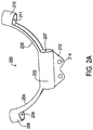
- the strain relief loop holder 200 of this example is shown in FIG. 2A .
- the strain relief loop holder 200 includes a body section 202 that defines an entry to and a corresponding lead passageway 207.
- a first arm 204 extends from the body section 202 on a first end and terminates at a first arm section 208 that defines a lead passageway 209.
- a second arm 206 extends from the body section 202 on a second end and terminates at a second arm section 210 that defines a lead passageway 211.
- the first arm 204 and the second arm 206 form an arc even when the medical lead 104 is not present.
- the first and second arms 204, 206 may be linear when the lead 104 is not installed as shown in FIG. 2C discussed below but upon looping the medical lead 104 through the strain relief holder 200, the first and second arms 204, 206 attain the arc as shown.
- the medical lead 104 passes through the arm segments 208, 210 and then intersects itself within the body section 202. Because the medical lead 104 passes through each arm segment 208, 210 only once but passes through the body section 202 twice to create the intersection point, the lead passageway 207 of the body segment 202 may have a larger diameter than the diameter of the arm segments 208, 210. The diameters may be sized so that the medical lead 104 is able to move axially so that the strain relief function is preserved.
- the strain relief holder 200 may be constructed of various materials.
- the strain relief holder 200 may be constructed of a thermal non-conductor such as a biocompatible polymer, examples including silicone, polyurethane, PEEK, polysulfones, and the like.
- the body section 202 insulates the body tissue from heating occurring at an intersection point of the loop within the body section 202.
- the strain relief holder 200 may instead be constructed of a thermal conductor such as a biocompatible metal, examples including MP35N, titanium, and the like. In that case, the body section 202 distributes the heating throughout the strain relief holder 200, including across all of the body section 202, the arms 204, 206, and the arm sections 208, 210.
- This particular example also includes an integral anchor tab 212.
- the anchor tab 212 provides one or more suture holes 214. These holes 214 allow a surgeon implanting the lead to suture the anchor tab 212, and hence the strain relief loop holder 200 and the medical lead 104 within it, to a particular location within the body 112.
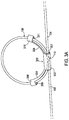
- FIG. 2B shows another example of a medical lead strain relief loop holder 220 that may be used in the system of FIG. 1 .
- This example is similar to that of FIG. 2A except that the arms 224 and 226 are positioned on the side of the loop 108 as opposed to the arms 204 and 206 being on the inside of the loop 108.
- the arm sections 228 and 230 define lead passageways 229 and 221 while the body section 222 defines a lead passageway 227.
- This example also includes the integral anchor 232 with suture holes 234.
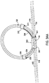
- FIG. 2C shows another example of a medical lead strain relief loop holder 240 that may be used in the system of FIG. 1 .
- This example is similar to that of FIG. 2A except that the arms 224 and 226 do not have pre-formed arcs. Instead, the arms 224 and 226 are constructed of an elastic material such as polyurethane or silicone that allows them to achieve an arc upon passing the lead 104 through the lead passageway 247 of the body 242 and through the passageways 241, 249 of the arm sections 248, 250.
- This example also includes the integral anchor 252 with suture holes 254.
- FIG. 3A shows a medical lead strain relief system including a similar strain relief loop holder 300 as that shown in FIG. 2A that may be used in the system of FIG. 1 .
- FIG. 3AA shows the same example but with two medical leads 104, 105 being looped through the holder 300. It will be appreciated that such a system may instead be designed to accommodate any number of leads passing through. However, this example in FIG. 3AA of two leads 104, 105 passing through a same strain relief loop holder 300 is particularly convenient where a single paddle 106 has two medical lead bodies that interconnect the paddle 106 to the medical device 102.
- 3AA can be seen within a body section 302, where the medical leads 104, 105 pass through a lead passageway 307.
- the medical leads 104, 105 pass through a lead passageway 311 of an arm section 310 as well as a lead passageway 309 of an arm section 308.
- the arm sections 308 and 310 are joined to the body section 302 by arms 304 and 306.
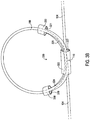
- FIG. 3B shows another example of a medical lead strain relief loop holder 320 that may be used in the system of FIG. 1 .
- This example is similar to that of FIG. 3A except that the arms 324 and 326 are positioned on the side of the loop 108 as in the example of FIG. 2B as opposed to the arms 304 and 306 being on the inside of the loop 108.
- the arm sections 328 and 330 define lead passageways 329 and 321 while the body section 322 defines a lead passageway 327.
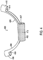
- FIG. 4 shows another example of a strain relief holder 400 that may be used in the system of FIG. 1 .
- the strain relief holder 400 includes a body section 402 defining a passageway 407, arms 404, 406 extending from the body section 402, and arm sections 408, 410 defining lead passageways 409, 411.
- the body section 402 which is constructed of a thermal non-conductor is also doped with a thermally and/or electrically conductive material 412.
- the conductive material 412 may be thermally conductive to facilitate heat dissipation, such as diamond dust where electrical conductivity is not desired.
- the conductive material 412 may additionally or alternatively be electrically conductive to alter the transmission-line characteristics at the intersection point 110.
- Examples of such an electrically conductive dopant material include tantalum or platinum.
- the dopant conductive material 412 may further enhance the ability of the strain relief loop holder 400 to reduce heating at the electrodes on the distal end of the lead 104.
- the dopant conductive material 412 may be included in the remainder of the strain relief holder 400 as well. It will be appreciated that the dopant 412 may be included within all of the various strain relief loop holders disclosed herein.
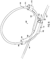
- FIG. 5 shows another example of a strain relief loop holder 500 that may be used in the system of FIG. 1 .
- the strain relief loop holder 500 includes two adjacent passageways 507, 513 established by a body section 502 that includes an extra barrel 503 defining the extra passageway 513.
- the arm 504 extends from the body segment 502 and more particularly from the lead passageway 507.
- the arm 506 extends from the body segment 502 and more particularly from the extra lead passageway 513 defined by the extra barrel 503 of the body segment 502.
- an arm segment 508 defines a lead passageway 509 that is aligned with the lead passageway 507 while the arm segment 510 defines a lead passageway 511 that is aligned with the lead passageway 513.
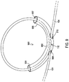
- FIG. 6 shows a medical lead strain relief system that may be used in the system of FIG. 1 and that includes the medical lead 104 looping through a strain relief loop holder 600 like that of FIG. 5 .
- the medical lead 104 passes through a lead passageway 613 defined by the extra barrel 603, then loops through a lead passageway 611 of an arm segment 610 of an arm 606 extending from the extra barrel 603.
- the medical lead 104 loops through a lead passageway 609 of an arm section 608 of an arm 604 extending from the body section 602.
- the intersection point 110' differs in that the medical lead 104 does not directly contact itself. Instead, the medical lead 104 is separated from itself at the intersection point 110' passing through separate lead passageways 607, 613 of the body segment 602. This separation may reduce the degree of excessive heating at the intersection point 110'. Meanwhile, in embodiments where the body segment 602 is thermally non-conductive, the body segment 602 continues to isolate the excess heating from the body 112. For embodiments where the body segment 602 is thermally conductive, the body segment 602 continues to distribute the heating of the intersection point 110' over a larger amount of tissue.
- FIG. 7 shows another example of a strain relief loop holder 700 that may be used in the system of FIG. 1 .
- the arms 704, 706 are abbreviated and arm segments are omitted from this figure for purposes of illustration of the perspective view.
- a body section 702 is constructed of a thermal non-conductor such as a polymer.
- a metal insert 712 such as a metal sleeve is embedded within the body section such that the medical lead passes through the metal insert 712 when passing through the passageway 707. This metal insert 712 enhances the benefit from heating at the intersection point within the body section 702 which further reduces the heating at the electrodes on the distal end of the medical lead 104.
- Examples of materials for the metal sleeve 712 include titanium, MP35N, and the like.
- FIG. 8 shows another example of a strain relief loop holder 800 that may be used in the system of FIG. 1 .
- the arms 804, 806 are abbreviated and arm segments are omitted from this figure for purposes of illustration of the perspective view.
- a body section 802 including an extra barrel 803 is constructed of a thermal non-conductor such as a polymer.
- a metal body 812 is embedded within the body section 802 between the two barrels such that the medical lead 104 passes through the lead passageways 807, 813 and the metal body 812 is present between the passes of the medical lead 104 at the intersection point.
- This metal body 812 also enhances the benefit from heating at the intersection point within the body section 802 which further reduces the heating at the electrodes on the distal end of the medical lead 104.
- Examples of materials for the metal body 812 include titanium, MP35N, and the like.
- FIG. 9 shows another example of a strain relief loop holder 900 that may be used in the system of FIG. 1 .
- This strain relief loop holder 900 is a continuous tube with a center section 902 and end sections 904, 906 together defining a lead passageway 907.
- the intersection point of the medical lead 104 occurs within the center section 902 and therefore the center section 902 may have a larger diameter than the end sections 904 906.
- the center section 902 may also define apertures 908 and 910 that provide an entry to allow the medical lead 104 to enter and exit the strain relief loop holder.
- This example may be constructed of thermal non-conductors or thermal conductors.
- a dopant or metal insert may be included as discussed above in relation to FIGS. 4 and 7 .
- FIG. 10 shows another example of a strain relief loop holder 1000 that may be used in the system of FIG. 1 .
- the strain relief loop holder 1000 utilizes continuous conjoined tubes forming center sections 1002 and 1003 and end sections 1004 and 1006 defining lead passageways 1004, 1009, respectively.
- each tube contains a single pass of the medical lead 104 and therefore both the center sections 1002, 1003 and the end sections 1004, 1006 are the same diameter in this example.
- This example may also be constructed of thermal non-conductors or thermal conductors.
- a dopant, metal insert, or metal body may be included as discussed above in relation to FIGS. 4 , 7, and 8 .
- FIG. 11 shows another example of a strain relief loop holder 1100 that may be used in the system of FIG. 1 and that utilizes a body 1102 with a single tube.
- the tube 1102 defines a lead passageway 1104.
- the lead 104 passes through the lead passageway 1104 loosely to form the strain relief loop 108 and intersection point 110 where the diameter of the lead passageway 1104 is larger than the lead body 104 to allow unrestricted axial movement of the lead 104 through the passageway 1104.
- This example may also be constructed of thermal non-conductors or thermal conductors.
- a dopant, metal insert, or metal body may be included as discussed above in relation to FIGS. 4 , 7, and 8 .
- FIG. 12 shows another example of a strain relief loop holder 1200 that may be used in the system of FIG. 1 and that utilizes a body 1202 that includes an additional tube 1203 to thereby form two adjacent central sections.
- the body 1202 including the additional tube 1203 defines lead passageways 1204 and 1206.
- the lead 104 passes through the lead passageways 1204, 1206 loosely to form the strain relief loop 108 and intersection point 110' where the diameter of the lead passageways 1204, 1206 are larger than the lead body 104 to allow unrestricted axial movement of the lead 104 through the passageways 1204, 1206.
- This example may also be constructed of thermal non-conductors or thermal conductors.
- a dopant, metal insert, or metal body may be included as discussed above in relation to FIGS. 4 , 7, and 8 .
- FIG. 13 shows another example of a strain relief loop holder 1300 that may be used in the system of FIG. 1 and that utilizes a body 1302 with a single tubular central section that defines two lead passageways 1304, 1306.
- the lead 104 passes through the lead passageways 1304, 1306 loosely to form the strain relief loop 108 where the diameter of the lead passageways 1304, 1306 is larger than the lead body 104 to allow unrestricted axial movement of the lead 104 through the passageways 1304, 1306.
- This example may also be constructed of thermal non-conductors or thermal conductors.
- a dopant, metal insert, or metal body may be included as discussed above in relation to FIGS. 4 , 7, and 8 .
- FIG. 14 shows another example of a strain relief loop holder 1400 that may be used in the system of FIG. 1 .
- the strain relief loop holder 1400 utilizes a body 1402 with a single tube to define a lead passageway 1404 at the intersection point 110 but also utilizes a looped coil 1406.
- the lead 104 passes through the lead passageway 1404 loosely to form the strain relief loop 108 where the diameter of the lead passageway 1404 is larger than the lead body 104 to allow unrestricted axial movement of the lead 104 through the passageway 1404.
- the loop 108 is constrained to a particular shape and size by the presence of the looped coil 1406 which is coupled to the body 1402.
- the looped coil 1406 may be constructed of non-conductive materials such as polyurethane, silicone, or conductive materials that have a non-conductive coating such as ETFE coated titanium, titanium molybdenum, or MP35N. This example may also be constructed of thermal non-conductors or thermal conductors. Furthermore, in the case of thermal non-conductor construction, a dopant, metal insert, or metal body may be included as discussed above in relation to FIGS. 4 , 7, and 8 .
- FIG. 15 shows another example of a strain relief loop holder 1500 that may be used in the system of FIG. 1 and that utilizes a body 1502 that provides a single tube.
- the body 1502 defines a lead passageway 1504. Additionally, the body 1502 is also looped.
- the lead 104 passes through the lead passageway 1504 loosely with the lead passageway 1504 to form the strain relief loop 108 where the diameter of the lead passageway 1504 is larger than the lead body 104 to allow unrestricted axial movement of the lead 104 through the passageway 1504.
- the looped shape of the body 1502 constrains the shape and size of the loop 108 of the lead 104.
- This example may also be constructed of thermal non-conductors or thermal conductors.
- a dopant, metal insert, or metal body may be included as discussed above in relation to FIGS. 4 , 7, and 8 .
- FIG. 16 shows another example of a strain relief loop holder 1600 that may be used in the system of FIG. 1 .
- the strain relief loop holder 1600 utilizes a body 1602 that forms a capsule to completely house the loop 108 of the lead 104 such that the passageway for the lead 104 is the entire internal volume of the strain relief loop holder 1600.
- the lead enters and exits the body 1602 through apertures 1604 and 1606 forming an entry to the interior volume of the body 1602.
- This example may also be constructed of thermal non-conductors or thermal conductors.
- a dopant, metal insert, or metal body may be included as discussed above in relation to FIGS. 4 , 7, and 8 .
- the lead body 104 could be affixed to one side of the holder so that the holder and the lead 104 are inseparable.
- the strain relief holder is already present on the lead 104 at the time of implant so that the holder is not inadvertently or intentionally omitted during the implantation procedure.
- the strain relief function is preserved.
- both leads 104, 105 may be affixed to the arm section 310 such as by a bond created by an adhesive or by melding the lead body to the arm section by reflowing the polymers of the two at that point.
Claims (14)
- Implantierbarer Zugentlastungsschlaufenhalter für eine medizinische Leitung, der Folgendes umfasst:ein Körpersegment (202), das wenigstens einen Durchgang (207) definiert,einen ersten Arm (204), der sich von einem ersten Ende des Körpersegments (202) aus erstreckt,ein erstes Armsegment (208) an einem Ende des ersten Arms (204) gegenüber dem Körpersegment (202), wobei das erste Armsegment einen ersten Armdurchgang (209) definiert,einen zweiten Arm (206), der sich von einem zweiten Ende des Körpersegments (202) aus erstreckt, undein zweites Armsegment (210) an dem Ende des zweiten Arms (206) gegenüber dem Körpersegment (202), wobei das zweite Armsegment (210) einen zweiten Armdurchgang (211) definiert.
- Implantierbarer Zugentlastungsschlaufenhalter nach Anspruch 1, wobei der erste Arm (204) und der zweite Arm (206) eine Bogenform haben.
- Implantierbarer Zugentlastungsschlaufenhalter nach Anspruch 1 oder 2, wobei das Körpersegment (202) einen einzelnen Durchgang (207) definiert und wobei sich sowohl der erste Arm (204) als auch der zweite Arm (206) von dem einzelnen Durchgang (207) aus erstrecken.
- Implantierbarer Zugentlastungsschlaufenhalter nach Anspruch 1 oder 2, wobei das Körpersegment einen ersten Durchgang (507) und einen zweiten Durchgang (513) definiert, wobei sich der erste Arm (504) von dem ersten Durchgang (507) aus erstreckt und wobei sich der zweite Arm (506) von dem zweiten Durchgang (513) aus erstreckt.
- Implantierbarer Zugentlastungsschlaufenhalter nach Anspruch 4, der ferner einen Metallkörper (812) zwischen dem ersten und dem zweiten Durchgang (507, 513) umfasst.
- Implantierbarer Zugentlastungsschlaufenhalter nach einem der Ansprüche 1 bis 4, wobei das Körpersegment (202), der erste Arm (204) und der zweite Arm (206) aus einem Polymer aufgebaut sind, wobei das Körpersegment (202) wahlweise mit einem leitfähigen Material dotiert ist.
- Implantierbarer Zugentlastungsschlaufenhalter nach Anspruch 6, der ferner einen Metalleinsatz (712) innerhalb des Körpersegments (702) umfasst.
- Implantierbarer Zugentlastungsschlaufenhalter nach einem der Ansprüche 1 bis 4, wobei das Körpersegment (202), der erste Arm (204) und der zweite Arm (206) aus einem Metall aufgebaut sind.
- Implantierbarer Zugentlastungsschlaufenhalter nach einem der Ansprüche 1 bis 8, der ferner eine Ankerlasche (212) umfasst, die sich von dem Körpersegment (202) aus erstreckt.
- Implantierbarer Zugentlastungsschlaufenhalter nach einem der Ansprüche 1 bis 9, wobei der wenigstens eine Körpersegment-Durchgang (207) einen Durchmesser hat, der größer ist als ein Durchmesser des ersten Armdurchgangs (209) und des zweiten Armdurchgangs (211) .
- Medizinisches Leitungszugentlastungssystem, das Folgendes umfasst:einen implantierbaren Zugentlastungsschlaufenhalter nach einem der vorhergehenden Ansprüche undeine medizinische Leitung (104), die durch den ersten Armdurchgang (209) hindurchgeht, wobei die medizinische Leitung durch das Hindurchgehen und Überschneiden innerhalb des Körpersegments eine Schlaufe bildet, wobei typischerweise die medizinische Leitung an ein medizinisches Gerät angeschlossen ist.
- Medizinisches Leitungszugentlastungssystem nach Anspruch 11, wobei das Körpersegment einen einzelnen Durchgang definiert, wobei sich sowohl der erste Arm als auch der zweite Arm von dem einzelnen Durchgang aus erstrecken und wobei sich die medizinische Leitung innerhalb des einzelnen Durchgangs überschneidet, oder wobei das Körpersegment einen ersten Durchgang angrenzend an einen zweiten Durchgang definiert, wobei sich der erste Arm von dem ersten Durchgang aus erstreckt und wobei sich der zweite Arm von dem zweiten Durchgang aus und wobei sich die medizinische Leitung durch das Hindurchgehen durch den ersten und den zweiten Durchgang innerhalb des Körpersegments überschneidet.
- Medizinisches Leitungszugentlastungssystem nach Anspruch 11, das ferner eine zur Schlaufe geschlungene Spirale umfasst, die an den Körper angeschlossen ist, und wobei die medizinische Leitung durch die zur Schlaufe geschlungene Spirale hindurchgeht.
- Medizinisches Leitungszugentlastungssystem nach einem der Ansprüche 11 bis 13, wobei der Körper einen thermischen Nichtleiter umfasst oder
wobei der Körper einen thermischen Leiter umfasst.
Applications Claiming Priority (2)
| Application Number | Priority Date | Filing Date | Title |
|---|---|---|---|
| US201261635784P | 2012-04-19 | 2012-04-19 | |
| PCT/US2013/023643 WO2013158190A1 (en) | 2012-04-19 | 2013-01-29 | Strain relief loop holders for medical leads and systems |
Publications (2)
| Publication Number | Publication Date |
|---|---|
| EP2838604A1 EP2838604A1 (de) | 2015-02-25 |
| EP2838604B1 true EP2838604B1 (de) | 2017-04-05 |
Family
ID=47747789
Family Applications (1)
| Application Number | Title | Priority Date | Filing Date |
|---|---|---|---|
| EP13705639.6A Active EP2838604B1 (de) | 2012-04-19 | 2013-01-29 | Zugentlastende schleifenhalter für medizinische leitungen und systeme damit |
Country Status (3)
| Country | Link |
|---|---|
| US (2) | US9561364B2 (de) |
| EP (1) | EP2838604B1 (de) |
| WO (1) | WO2013158190A1 (de) |
Families Citing this family (16)
| Publication number | Priority date | Publication date | Assignee | Title |
|---|---|---|---|---|
| US9072897B2 (en) | 2007-03-09 | 2015-07-07 | Mainstay Medical Limited | Systems and methods for restoring muscle function to the lumbar spine |
| US11679261B2 (en) | 2007-03-09 | 2023-06-20 | Mainstay Medical Limited | Systems and methods for enhancing function of spine stabilization muscles associated with a spine surgery intervention |
| US11679262B2 (en) | 2007-03-09 | 2023-06-20 | Mainstay Medical Limited | Systems and methods for restoring muscle function to the lumbar spine |
| US10925637B2 (en) | 2010-03-11 | 2021-02-23 | Mainstay Medical Limited | Methods of implanting electrode leads for use with implantable neuromuscular electrical stimulator |
| ES2827186T3 (es) | 2007-03-09 | 2021-05-20 | Mainstay Medical Ltd | Sistema de estimulación eléctrica neuromuscular |
| US11331488B2 (en) | 2007-03-09 | 2022-05-17 | Mainstay Medical Limited | Systems and methods for enhancing function of spine stabilization muscles associated with a spine surgery intervention |
| US11786725B2 (en) | 2012-06-13 | 2023-10-17 | Mainstay Medical Limited | Systems and methods for restoring muscle function to the lumbar spine and kits for implanting the same |
| US9950159B2 (en) | 2013-10-23 | 2018-04-24 | Mainstay Medical Limited | Systems and methods for restoring muscle function to the lumbar spine and kits for implanting the same |
| CA2792529C (en) | 2010-03-11 | 2018-06-05 | Mainstay Medical, Inc. | Modular stimulator for treatment of back pain, implantable rf ablation system and methods of use |
| US11684774B2 (en) | 2010-03-11 | 2023-06-27 | Mainstay Medical Limited | Electrical stimulator for treatment of back pain and methods of use |
| US9999763B2 (en) | 2012-06-13 | 2018-06-19 | Mainstay Medical Limited | Apparatus and methods for anchoring electrode leads adjacent to nervous tissue |
| US9186501B2 (en) | 2012-06-13 | 2015-11-17 | Mainstay Medical Limited | Systems and methods for implanting electrode leads for use with implantable neuromuscular electrical stimulator |
| US10195419B2 (en) * | 2012-06-13 | 2019-02-05 | Mainstay Medical Limited | Electrode leads for use with implantable neuromuscular electrical stimulator |
| US9402996B2 (en) * | 2014-02-11 | 2016-08-02 | Cardiac Pacemakers, Inc. | RF shield for an implantable lead |
| US10471268B2 (en) | 2014-10-16 | 2019-11-12 | Mainstay Medical Limited | Systems and methods for monitoring muscle rehabilitation |
| US10327810B2 (en) | 2016-07-05 | 2019-06-25 | Mainstay Medical Limited | Systems and methods for enhanced implantation of electrode leads between tissue layers |
Family Cites Families (11)
| Publication number | Priority date | Publication date | Assignee | Title |
|---|---|---|---|---|
| US5376108A (en) * | 1993-05-20 | 1994-12-27 | Telectronics Pacing Systems, Inc. | Electrode lead anchoring apparatus and method employing dual suture collars |
| US6471676B1 (en) * | 2000-03-21 | 2002-10-29 | Novartis Nutrition Ag | Catheter and feeding tube retention device and method of use |
| US7454251B2 (en) | 2003-05-29 | 2008-11-18 | The Cleveland Clinic Foundation | Excess lead retaining and management devices and methods of using same |
| WO2006012050A2 (en) | 2004-06-30 | 2006-02-02 | Cvrx, Inc. | Connection structures for extra-vascular electrode lead body |
| US7917213B2 (en) | 2005-11-04 | 2011-03-29 | Kenergy, Inc. | MRI compatible implanted electronic medical lead |
| US7769443B2 (en) | 2006-09-06 | 2010-08-03 | Giancarlo Barolat | Implantable reel for coiling an implantable elongated member |
| MY177188A (en) | 2006-12-11 | 2020-09-09 | Medic Domain M Sdn Bhd | A device for protecting and securing medical device at a venipuncture site |
| US8295948B2 (en) | 2009-07-21 | 2012-10-23 | Boston Scientific Neuromodulation Corporation | Tubular lead anchor and methods and devices using the anchor |
| US20110034983A1 (en) | 2009-08-07 | 2011-02-10 | Pacesetter, Inc. | Implantable medical device lead incorporating a conductive sheath surrounding insulated coils to reduce lead heating during mri |
| US9427552B2 (en) | 2010-06-30 | 2016-08-30 | Bernard Engelhardt | Medical tubing and catheter control |
| US8483845B2 (en) * | 2011-03-11 | 2013-07-09 | Greatbatch Ltd. | Anchor for implantable medical device |
-
2013
- 2013-01-29 EP EP13705639.6A patent/EP2838604B1/de active Active
- 2013-01-29 WO PCT/US2013/023643 patent/WO2013158190A1/en active Application Filing
- 2013-01-29 US US14/395,195 patent/US9561364B2/en active Active
-
2017
- 2017-02-06 US US15/426,051 patent/US10092748B2/en active Active
Non-Patent Citations (1)
| Title |
|---|
| "Bus Drop Cable Supports and Clamps", 1 September 2010 (2010-09-01), XP055231800, Retrieved from the Internet <URL:www.appletonelec.com> [retrieved on 20151126] * |
Also Published As
| Publication number | Publication date |
|---|---|
| US9561364B2 (en) | 2017-02-07 |
| US20150134035A1 (en) | 2015-05-14 |
| US20170182313A1 (en) | 2017-06-29 |
| WO2013158190A1 (en) | 2013-10-24 |
| US10092748B2 (en) | 2018-10-09 |
| EP2838604A1 (de) | 2015-02-25 |
Similar Documents
| Publication | Publication Date | Title |
|---|---|---|
| US10092748B2 (en) | Strain relief loop holders for medical leads and systems | |
| JP6953332B2 (ja) | 移植式導線 | |
| US10279165B2 (en) | Implantable medical devices, systems and components thereof | |
| CN105873630B (zh) | 用于通过经血管神经刺激辅助呼吸的装置和方法 | |
| US8801728B2 (en) | Introduction of medical lead into patient | |
| US8676347B2 (en) | Braided lead with embedded fixation structures | |
| US7395120B2 (en) | Telescoping, dual-site pacing lead | |
| US8224456B2 (en) | Directional stimulation lead and orientation system | |
| US7272448B1 (en) | Medical lead for placement in the pericardial sac | |
| EP3590575B1 (de) | Elektrode mit einem beweglichen einsatzstopfen | |
| US10086191B2 (en) | Medical leads having a distal body and an openly coiled filar | |
| US20030069623A1 (en) | Implantable percutaneous stimulation lead with lead carrier | |
| US20090319012A1 (en) | Modular stimulation lead network | |
| CN101505824A (zh) | 带有分流电极的电极系统 | |
| US20060036306A1 (en) | Telescoping, dual-site pacing lead | |
| JP2015508701A (ja) | ユニファイラーコイル状ケーブルを備える埋込型医療装置リード | |
| CN105056397A (zh) | 植入式神经电刺激电极组件及其应用方法 | |
| JP5178706B2 (ja) | 非直線型電極アレイ | |
| US11497919B2 (en) | Communication amplification device comprising retention elements for an implantable capsule | |
| EP3463230A1 (de) | Vorrichtungen und verfahren zur behandlung von tinnitus mit elektrischer stimulation | |
| CN111787973A (zh) | 神经监测和/或刺激电极组件 | |
| US20090281409A1 (en) | Reinforced medical device | |
| CN205055188U (zh) | 植入式神经电刺激电极组件及其电极导管 | |
| CN110325243A (zh) | 外科植入系统 | |
| US20140316504A1 (en) | Implantable indifferent electrode |
Legal Events
| Date | Code | Title | Description |
|---|---|---|---|
| PUAI | Public reference made under article 153(3) epc to a published international application that has entered the european phase |
Free format text: ORIGINAL CODE: 0009012 |
|
| 17P | Request for examination filed |
Effective date: 20141117 |
|
| AK | Designated contracting states |
Kind code of ref document: A1 Designated state(s): AL AT BE BG CH CY CZ DE DK EE ES FI FR GB GR HR HU IE IS IT LI LT LU LV MC MK MT NL NO PL PT RO RS SE SI SK SM TR |
|
| AX | Request for extension of the european patent |
Extension state: BA ME |
|
| DAX | Request for extension of the european patent (deleted) | ||
| 17Q | First examination report despatched |
Effective date: 20151203 |
|
| GRAP | Despatch of communication of intention to grant a patent |
Free format text: ORIGINAL CODE: EPIDOSNIGR1 |
|
| RIC1 | Information provided on ipc code assigned before grant |
Ipc: H01R 13/58 20060101ALI20161107BHEP Ipc: G01K 1/14 20060101ALI20161107BHEP Ipc: A61N 1/08 20060101ALI20161107BHEP Ipc: A61M 25/02 20060101ALI20161107BHEP Ipc: A61N 1/05 20060101AFI20161107BHEP |
|
| INTG | Intention to grant announced |
Effective date: 20161206 |
|
| GRAS | Grant fee paid |
Free format text: ORIGINAL CODE: EPIDOSNIGR3 |
|
| GRAA | (expected) grant |
Free format text: ORIGINAL CODE: 0009210 |
|
| AK | Designated contracting states |
Kind code of ref document: B1 Designated state(s): AL AT BE BG CH CY CZ DE DK EE ES FI FR GB GR HR HU IE IS IT LI LT LU LV MC MK MT NL NO PL PT RO RS SE SI SK SM TR |
|
| REG | Reference to a national code |
Ref country code: GB Ref legal event code: FG4D |
|
| REG | Reference to a national code |
Ref country code: CH Ref legal event code: EP |
|
| REG | Reference to a national code |
Ref country code: AT Ref legal event code: REF Ref document number: 881225 Country of ref document: AT Kind code of ref document: T Effective date: 20170415 |
|
| REG | Reference to a national code |
Ref country code: IE Ref legal event code: FG4D |
|
| REG | Reference to a national code |
Ref country code: DE Ref legal event code: R096 Ref document number: 602013019410 Country of ref document: DE |
|
| REG | Reference to a national code |
Ref country code: NL Ref legal event code: MP Effective date: 20170405 |
|
| REG | Reference to a national code |
Ref country code: LT Ref legal event code: MG4D |
|
| REG | Reference to a national code |
Ref country code: AT Ref legal event code: MK05 Ref document number: 881225 Country of ref document: AT Kind code of ref document: T Effective date: 20170405 |
|
| PG25 | Lapsed in a contracting state [announced via postgrant information from national office to epo] |
Ref country code: NL Free format text: LAPSE BECAUSE OF FAILURE TO SUBMIT A TRANSLATION OF THE DESCRIPTION OR TO PAY THE FEE WITHIN THE PRESCRIBED TIME-LIMIT Effective date: 20170405 |
|
| PG25 | Lapsed in a contracting state [announced via postgrant information from national office to epo] |
Ref country code: NO Free format text: LAPSE BECAUSE OF FAILURE TO SUBMIT A TRANSLATION OF THE DESCRIPTION OR TO PAY THE FEE WITHIN THE PRESCRIBED TIME-LIMIT Effective date: 20170705 Ref country code: AT Free format text: LAPSE BECAUSE OF FAILURE TO SUBMIT A TRANSLATION OF THE DESCRIPTION OR TO PAY THE FEE WITHIN THE PRESCRIBED TIME-LIMIT Effective date: 20170405 Ref country code: LT Free format text: LAPSE BECAUSE OF FAILURE TO SUBMIT A TRANSLATION OF THE DESCRIPTION OR TO PAY THE FEE WITHIN THE PRESCRIBED TIME-LIMIT Effective date: 20170405 Ref country code: HR Free format text: LAPSE BECAUSE OF FAILURE TO SUBMIT A TRANSLATION OF THE DESCRIPTION OR TO PAY THE FEE WITHIN THE PRESCRIBED TIME-LIMIT Effective date: 20170405 Ref country code: ES Free format text: LAPSE BECAUSE OF FAILURE TO SUBMIT A TRANSLATION OF THE DESCRIPTION OR TO PAY THE FEE WITHIN THE PRESCRIBED TIME-LIMIT Effective date: 20170405 Ref country code: GR Free format text: LAPSE BECAUSE OF FAILURE TO SUBMIT A TRANSLATION OF THE DESCRIPTION OR TO PAY THE FEE WITHIN THE PRESCRIBED TIME-LIMIT Effective date: 20170706 Ref country code: FI Free format text: LAPSE BECAUSE OF FAILURE TO SUBMIT A TRANSLATION OF THE DESCRIPTION OR TO PAY THE FEE WITHIN THE PRESCRIBED TIME-LIMIT Effective date: 20170405 |
|
| PG25 | Lapsed in a contracting state [announced via postgrant information from national office to epo] |
Ref country code: SE Free format text: LAPSE BECAUSE OF FAILURE TO SUBMIT A TRANSLATION OF THE DESCRIPTION OR TO PAY THE FEE WITHIN THE PRESCRIBED TIME-LIMIT Effective date: 20170405 Ref country code: PL Free format text: LAPSE BECAUSE OF FAILURE TO SUBMIT A TRANSLATION OF THE DESCRIPTION OR TO PAY THE FEE WITHIN THE PRESCRIBED TIME-LIMIT Effective date: 20170405 Ref country code: IS Free format text: LAPSE BECAUSE OF FAILURE TO SUBMIT A TRANSLATION OF THE DESCRIPTION OR TO PAY THE FEE WITHIN THE PRESCRIBED TIME-LIMIT Effective date: 20170805 Ref country code: RS Free format text: LAPSE BECAUSE OF FAILURE TO SUBMIT A TRANSLATION OF THE DESCRIPTION OR TO PAY THE FEE WITHIN THE PRESCRIBED TIME-LIMIT Effective date: 20170405 Ref country code: LV Free format text: LAPSE BECAUSE OF FAILURE TO SUBMIT A TRANSLATION OF THE DESCRIPTION OR TO PAY THE FEE WITHIN THE PRESCRIBED TIME-LIMIT Effective date: 20170405 Ref country code: BG Free format text: LAPSE BECAUSE OF FAILURE TO SUBMIT A TRANSLATION OF THE DESCRIPTION OR TO PAY THE FEE WITHIN THE PRESCRIBED TIME-LIMIT Effective date: 20170705 |
|
| REG | Reference to a national code |
Ref country code: DE Ref legal event code: R097 Ref document number: 602013019410 Country of ref document: DE |
|
| REG | Reference to a national code |
Ref country code: FR Ref legal event code: PLFP Year of fee payment: 6 |
|
| PG25 | Lapsed in a contracting state [announced via postgrant information from national office to epo] |
Ref country code: RO Free format text: LAPSE BECAUSE OF FAILURE TO SUBMIT A TRANSLATION OF THE DESCRIPTION OR TO PAY THE FEE WITHIN THE PRESCRIBED TIME-LIMIT Effective date: 20170405 Ref country code: DK Free format text: LAPSE BECAUSE OF FAILURE TO SUBMIT A TRANSLATION OF THE DESCRIPTION OR TO PAY THE FEE WITHIN THE PRESCRIBED TIME-LIMIT Effective date: 20170405 Ref country code: SK Free format text: LAPSE BECAUSE OF FAILURE TO SUBMIT A TRANSLATION OF THE DESCRIPTION OR TO PAY THE FEE WITHIN THE PRESCRIBED TIME-LIMIT Effective date: 20170405 Ref country code: EE Free format text: LAPSE BECAUSE OF FAILURE TO SUBMIT A TRANSLATION OF THE DESCRIPTION OR TO PAY THE FEE WITHIN THE PRESCRIBED TIME-LIMIT Effective date: 20170405 Ref country code: CZ Free format text: LAPSE BECAUSE OF FAILURE TO SUBMIT A TRANSLATION OF THE DESCRIPTION OR TO PAY THE FEE WITHIN THE PRESCRIBED TIME-LIMIT Effective date: 20170405 |
|
| PLBE | No opposition filed within time limit |
Free format text: ORIGINAL CODE: 0009261 |
|
| STAA | Information on the status of an ep patent application or granted ep patent |
Free format text: STATUS: NO OPPOSITION FILED WITHIN TIME LIMIT |
|
| PG25 | Lapsed in a contracting state [announced via postgrant information from national office to epo] |
Ref country code: IT Free format text: LAPSE BECAUSE OF FAILURE TO SUBMIT A TRANSLATION OF THE DESCRIPTION OR TO PAY THE FEE WITHIN THE PRESCRIBED TIME-LIMIT Effective date: 20170405 Ref country code: SM Free format text: LAPSE BECAUSE OF FAILURE TO SUBMIT A TRANSLATION OF THE DESCRIPTION OR TO PAY THE FEE WITHIN THE PRESCRIBED TIME-LIMIT Effective date: 20170405 |
|
| 26N | No opposition filed |
Effective date: 20180108 |
|
| PG25 | Lapsed in a contracting state [announced via postgrant information from national office to epo] |
Ref country code: SI Free format text: LAPSE BECAUSE OF FAILURE TO SUBMIT A TRANSLATION OF THE DESCRIPTION OR TO PAY THE FEE WITHIN THE PRESCRIBED TIME-LIMIT Effective date: 20170405 |
|
| REG | Reference to a national code |
Ref country code: CH Ref legal event code: PL |
|
| GBPC | Gb: european patent ceased through non-payment of renewal fee |
Effective date: 20180129 |
|
| PG25 | Lapsed in a contracting state [announced via postgrant information from national office to epo] |
Ref country code: LU Free format text: LAPSE BECAUSE OF NON-PAYMENT OF DUE FEES Effective date: 20180129 |
|
| REG | Reference to a national code |
Ref country code: IE Ref legal event code: MM4A |
|
| REG | Reference to a national code |
Ref country code: BE Ref legal event code: MM Effective date: 20180131 |
|
| PG25 | Lapsed in a contracting state [announced via postgrant information from national office to epo] |
Ref country code: LI Free format text: LAPSE BECAUSE OF NON-PAYMENT OF DUE FEES Effective date: 20180131 Ref country code: BE Free format text: LAPSE BECAUSE OF NON-PAYMENT OF DUE FEES Effective date: 20180131 Ref country code: CH Free format text: LAPSE BECAUSE OF NON-PAYMENT OF DUE FEES Effective date: 20180131 Ref country code: GB Free format text: LAPSE BECAUSE OF NON-PAYMENT OF DUE FEES Effective date: 20180129 |
|
| PG25 | Lapsed in a contracting state [announced via postgrant information from national office to epo] |
Ref country code: IE Free format text: LAPSE BECAUSE OF NON-PAYMENT OF DUE FEES Effective date: 20180129 |
|
| PG25 | Lapsed in a contracting state [announced via postgrant information from national office to epo] |
Ref country code: MC Free format text: LAPSE BECAUSE OF FAILURE TO SUBMIT A TRANSLATION OF THE DESCRIPTION OR TO PAY THE FEE WITHIN THE PRESCRIBED TIME-LIMIT Effective date: 20170405 |
|
| PG25 | Lapsed in a contracting state [announced via postgrant information from national office to epo] |
Ref country code: MT Free format text: LAPSE BECAUSE OF NON-PAYMENT OF DUE FEES Effective date: 20180129 |
|
| PG25 | Lapsed in a contracting state [announced via postgrant information from national office to epo] |
Ref country code: TR Free format text: LAPSE BECAUSE OF FAILURE TO SUBMIT A TRANSLATION OF THE DESCRIPTION OR TO PAY THE FEE WITHIN THE PRESCRIBED TIME-LIMIT Effective date: 20170405 |
|
| PG25 | Lapsed in a contracting state [announced via postgrant information from national office to epo] |
Ref country code: PT Free format text: LAPSE BECAUSE OF FAILURE TO SUBMIT A TRANSLATION OF THE DESCRIPTION OR TO PAY THE FEE WITHIN THE PRESCRIBED TIME-LIMIT Effective date: 20170405 |
|
| PG25 | Lapsed in a contracting state [announced via postgrant information from national office to epo] |
Ref country code: HU Free format text: LAPSE BECAUSE OF FAILURE TO SUBMIT A TRANSLATION OF THE DESCRIPTION OR TO PAY THE FEE WITHIN THE PRESCRIBED TIME-LIMIT; INVALID AB INITIO Effective date: 20130129 Ref country code: MK Free format text: LAPSE BECAUSE OF NON-PAYMENT OF DUE FEES Effective date: 20170405 Ref country code: CY Free format text: LAPSE BECAUSE OF FAILURE TO SUBMIT A TRANSLATION OF THE DESCRIPTION OR TO PAY THE FEE WITHIN THE PRESCRIBED TIME-LIMIT Effective date: 20170405 |
|
| PG25 | Lapsed in a contracting state [announced via postgrant information from national office to epo] |
Ref country code: AL Free format text: LAPSE BECAUSE OF FAILURE TO SUBMIT A TRANSLATION OF THE DESCRIPTION OR TO PAY THE FEE WITHIN THE PRESCRIBED TIME-LIMIT Effective date: 20170405 |
|
| PGFP | Annual fee paid to national office [announced via postgrant information from national office to epo] |
Ref country code: FR Payment date: 20231219 Year of fee payment: 12 |
|
| PGFP | Annual fee paid to national office [announced via postgrant information from national office to epo] |
Ref country code: DE Payment date: 20231219 Year of fee payment: 12 |