EP2838323B1 - Plasma generation device, vapor deposition device, and plasma generation method - Google Patents
Plasma generation device, vapor deposition device, and plasma generation method Download PDFInfo
- Publication number
- EP2838323B1 EP2838323B1 EP13775531.0A EP13775531A EP2838323B1 EP 2838323 B1 EP2838323 B1 EP 2838323B1 EP 13775531 A EP13775531 A EP 13775531A EP 2838323 B1 EP2838323 B1 EP 2838323B1
- Authority
- EP
- European Patent Office
- Prior art keywords
- plasma
- electrode
- guns
- plasma generation
- converging
- Prior art date
- Legal status (The legal status is an assumption and is not a legal conclusion. Google has not performed a legal analysis and makes no representation as to the accuracy of the status listed.)
- Not-in-force
Links
Images

Classifications
-
- H—ELECTRICITY
- H01—ELECTRIC ELEMENTS
- H01J—ELECTRIC DISCHARGE TUBES OR DISCHARGE LAMPS
- H01J37/00—Discharge tubes with provision for introducing objects or material to be exposed to the discharge, e.g. for the purpose of examination or processing thereof
- H01J37/32—Gas-filled discharge tubes
- H01J37/34—Gas-filled discharge tubes operating with cathodic sputtering
- H01J37/3411—Constructional aspects of the reactor
-
- C—CHEMISTRY; METALLURGY
- C23—COATING METALLIC MATERIAL; COATING MATERIAL WITH METALLIC MATERIAL; CHEMICAL SURFACE TREATMENT; DIFFUSION TREATMENT OF METALLIC MATERIAL; COATING BY VACUUM EVAPORATION, BY SPUTTERING, BY ION IMPLANTATION OR BY CHEMICAL VAPOUR DEPOSITION, IN GENERAL; INHIBITING CORROSION OF METALLIC MATERIAL OR INCRUSTATION IN GENERAL
- C23C—COATING METALLIC MATERIAL; COATING MATERIAL WITH METALLIC MATERIAL; SURFACE TREATMENT OF METALLIC MATERIAL BY DIFFUSION INTO THE SURFACE, BY CHEMICAL CONVERSION OR SUBSTITUTION; COATING BY VACUUM EVAPORATION, BY SPUTTERING, BY ION IMPLANTATION OR BY CHEMICAL VAPOUR DEPOSITION, IN GENERAL
- C23C14/00—Coating by vacuum evaporation, by sputtering or by ion implantation of the coating forming material
- C23C14/22—Coating by vacuum evaporation, by sputtering or by ion implantation of the coating forming material characterised by the process of coating
- C23C14/24—Vacuum evaporation
- C23C14/32—Vacuum evaporation by explosion; by evaporation and subsequent ionisation of the vapours, e.g. ion-plating
-
- C—CHEMISTRY; METALLURGY
- C23—COATING METALLIC MATERIAL; COATING MATERIAL WITH METALLIC MATERIAL; CHEMICAL SURFACE TREATMENT; DIFFUSION TREATMENT OF METALLIC MATERIAL; COATING BY VACUUM EVAPORATION, BY SPUTTERING, BY ION IMPLANTATION OR BY CHEMICAL VAPOUR DEPOSITION, IN GENERAL; INHIBITING CORROSION OF METALLIC MATERIAL OR INCRUSTATION IN GENERAL
- C23C—COATING METALLIC MATERIAL; COATING MATERIAL WITH METALLIC MATERIAL; SURFACE TREATMENT OF METALLIC MATERIAL BY DIFFUSION INTO THE SURFACE, BY CHEMICAL CONVERSION OR SUBSTITUTION; COATING BY VACUUM EVAPORATION, BY SPUTTERING, BY ION IMPLANTATION OR BY CHEMICAL VAPOUR DEPOSITION, IN GENERAL
- C23C14/00—Coating by vacuum evaporation, by sputtering or by ion implantation of the coating forming material
- C23C14/22—Coating by vacuum evaporation, by sputtering or by ion implantation of the coating forming material characterised by the process of coating
- C23C14/34—Sputtering
- C23C14/35—Sputtering by application of a magnetic field, e.g. magnetron sputtering
-
- H—ELECTRICITY
- H01—ELECTRIC ELEMENTS
- H01J—ELECTRIC DISCHARGE TUBES OR DISCHARGE LAMPS
- H01J37/00—Discharge tubes with provision for introducing objects or material to be exposed to the discharge, e.g. for the purpose of examination or processing thereof
- H01J37/32—Gas-filled discharge tubes
- H01J37/32009—Arrangements for generation of plasma specially adapted for examination or treatment of objects, e.g. plasma sources
- H01J37/32055—Arc discharge
-
- H—ELECTRICITY
- H01—ELECTRIC ELEMENTS
- H01J—ELECTRIC DISCHARGE TUBES OR DISCHARGE LAMPS
- H01J37/00—Discharge tubes with provision for introducing objects or material to be exposed to the discharge, e.g. for the purpose of examination or processing thereof
- H01J37/32—Gas-filled discharge tubes
- H01J37/32431—Constructional details of the reactor
- H01J37/3266—Magnetic control means
-
- H—ELECTRICITY
- H01—ELECTRIC ELEMENTS
- H01J—ELECTRIC DISCHARGE TUBES OR DISCHARGE LAMPS
- H01J37/00—Discharge tubes with provision for introducing objects or material to be exposed to the discharge, e.g. for the purpose of examination or processing thereof
- H01J37/32—Gas-filled discharge tubes
- H01J37/34—Gas-filled discharge tubes operating with cathodic sputtering
- H01J37/3411—Constructional aspects of the reactor
- H01J37/345—Magnet arrangements in particular for cathodic sputtering apparatus
- H01J37/3458—Electromagnets in particular for cathodic sputtering apparatus
-
- H—ELECTRICITY
- H05—ELECTRIC TECHNIQUES NOT OTHERWISE PROVIDED FOR
- H05H—PLASMA TECHNIQUE; PRODUCTION OF ACCELERATED ELECTRICALLY-CHARGED PARTICLES OR OF NEUTRONS; PRODUCTION OR ACCELERATION OF NEUTRAL MOLECULAR OR ATOMIC BEAMS
- H05H1/00—Generating plasma; Handling plasma
- H05H1/24—Generating plasma
- H05H1/46—Generating plasma using applied electromagnetic fields, e.g. high frequency or microwave energy
Definitions
- the present invention relates to a plasma generation apparatus, a deposition apparatus, and a plasma generation method.
- the plasma assist method by which a chemical reaction of a deposition material is accelerated due to plasma generated in a chamber at the time of deposition.
- the plasma is normally formed by a plasma gun which injects a discharge gas to form the plasma while emitting electrons to ionize the discharge gas.
- the plasma gun includes a converging coil for forming a magnetic flux to guide the emitted electrons.
- the converging coil When the converging coil is provided, the electrons emitted from the plasma gun move while winding around a magnetic field formed by the converging coil, so that the plasma can reach a position far from the plasma gun.
- Fig. 3 shows a deposition apparatus in which plasma guns 22 are oppositely arranged on both sides of a chamber 21.
- the plasma gun 22 is a pressure-gradient type plasma gun and includes a cathode 23 for emitting electrons, a first electrode 24 and a second electrode 25 for forming voltage gradients, a feedback electrode 26 for collecting the electrons, and a converging coil 27 for forming a magnetic flux to guide the electrons.
- a discharge gas is injected so as to penetrate centers of those components.
- the magnetic fluxes formed by the converging coils 27 in the opposed plasma guns 22 repel each other.
- the electrons emitted from the plasma gun 22 travel while winding around the magnetic flux formed by the converging coil 27, so that they turn back along the repelling magnetic flux and return to each feedback electrode 26 as shown by dotted lines in the drawing. Therefore, the electrons are not sufficiently supplied to an intermediate position of the opposed plasma guns 22, and the plasma is low in density at the position, so that an imbalanced discharge region P is formed as shown in the drawing.
- Patent Document 1 Japanese Patent Laid-open Publication No. JP 7-254315
- a plasma generation apparatus includes two oppositely arranged plasma guns each injecting a discharge gas to be ionized and having a cathode for emitting electrons, and a converging coil for forming a magnetic flux to guide the emitted electrons, in which polarities of the converging coils with respect to the cathodes in the two plasma guns are opposite to each other.
- the magnetic fluxes formed by the converging coils in the opposed plasma guns are integrated with each other, the integrated magnetic flux is formed so as to penetrate both of the plasma guns.
- the electrons emitted from the plasma gun can more surely travel straight, so that the plasma density can be prevented from being lowered in the center.
- the chemical reaction at the time of the deposition can be uniformly caused over a wide range.
- the plasma gun is a pressure-gradient type plasma gun and includes a first electrode and a second electrode between the cathode and the converging coil, and the second electrode may internally house an electrode internal magnet for forming a magnetic flux having the same direction as the magnetic flux formed by the converging coil.
- the discharge can be stably performed under the condition that the electrons are trapped by the magnetic fluxes inside the plasma gun.
- the two plasma guns may be driven by two drive circuits insulated from each other, respectively.
- the discharge amount of the one plasma gun can be adjusted so as not to become larger due to asymmetry of a space or the like, so that the plasma can be prevented from becoming imbalanced.
- At least one of a position and an angle of the converging coil may be individually adjustable.
- the plasma gun may include a feedback electrode for collecting the electrons emitted from the cathode, and the feedback electrode may be connected to a circuit in the opposed plasma gun.
- a deposition apparatus has any one of the above plasma generation apparatuses.
- the plasma can be uniformly generated over a wide range. Therefore, at the time of the deposition, the chemical reaction is uniformly caused in the deposition material, so that the deposition target film can be uniformly formed even on the large-size deposition target body.
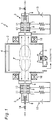
- Fig. 1 shows a configuration of a deposition apparatus 1 according to a first embodiment of the present invention.
- the deposition apparatus 1 includes a chamber 2 whose inside can be evacuated, and a pair of pressure-gradient type plasma guns 3 each arranged so as to see the inside of the chamber 2 through an opening provided in a side wall on each side of the chamber 2.
- a glass substrate 4 serving as a deposition target body can be held in an upper portion in an inner space of the chamber 2 so that metal is deposited onto its surface, and a crucible 5 for dissolving a deposition material is arranged in a bottom portion in the inner space thereof.
- the crucible 5 is provided with a heater 5a for heating the deposition material.
- the heater 5a can adopt a DC or AC resistance heating method, and a method using an electron beam as well.
- the plasma gun 3 has a cathode 6 for emitting electrons, a first electrode 7 and a second electrode 8 for forming potential gradients along an orbit of the electrons, a feedback electrode 9 for collecting the electrons emitted from the cathode 6, and an converging coil 10 for forming a magnetic flux for guiding the electrons emitted from the cathode 6.
- the first electrode 7 is an annular hollow electrode internally housing a first electrode internal magnet 11 composed of a permanent magnet.
- the second electrode is an annular hollow electrode internally housing a second electrode internal magnet 12 composed of an air core coil.
- the components of the plasma gun 3 and the plasma gun 3 are connected to the chamber 2 with a tube made of metal or glass, in order to ensure airtightness.
- each of the two plasma guns 3 has a drive circuit 13 for applying a discharge voltage to the cathode 6, the first electrode 7, the second electrode 8, and the feedback electrode 9.
- the two drive circuits 13 are electrically insulated from each other and can be separately adjusted.
- each of the plasma guns 3 injects a discharge gas such as argon gas which is ionized and becomes plasma so that the discharge gas penetrates centers of the cathode 6, the first electrode 7, the second electrode 8, the feedback electrode 9, and converging coil 10, and the plasma gun 3 has an adjusting valve 14 for adjusting a flow amount of the injected discharge gas individually.
- a DC voltage is applied from a power supply (not shown) to the converging coil 10 and the second electrode internal magnet 12 so that they have the same polarity direction.
- Each of the converging coil 10 and the second electrode internal magnet 12 is wound so that a current flows around a center axis of the plasma gun 3, and forms a magnetic flux which penetrates an inside of the coil.
- the polarity shown in the drawing only shows the direction of a magnetic pole, and it does not mean that a magnetic flux extends from the pole shown in the drawing.
- the polarity of the converging coil 10 and the electrode internal magnet 12 toward the cathode 6 in the right plasma gun 3 is opposite to that in the left plasma gun 3. That is, all of the converging coils 10 and the electrode internal magnets 12 have the same absolute polarities. More specifically, in the drawing, the S pole is provided on the left side and the N pole is provided on the right side, as a whole. Therefore, the magnetic fluxes formed by the converging coils 10 and the electrode internal magnets 12 on both sides are integrated with each other, so that the integrated magnetic flux is formed so as to linearly penetrate the right and left plasma guns 3 along the center axes of the right and left plasma guns 3.
- the electrons emitted from the cathode 6 travel while winding around the magnetic flux going straight between the right and left plasma guns 3.
- the electrons emitted from the plasma guns 3 on both sides repel from each other by coulomb force, and separate from the magnetic flux in a center portion of the chamber 2, and then return to the respective feedback electrodes 9.
- the drive circuits 13 of the two plasma guns 3 are insulated from each other, the number of electrons returning to the feedback electrode 9 is the same as that of the electrons emitted from the cathode 6 in the same plasma gun 3.
- the electrons evenly return to each of the feedback electrodes 9, so that there is no imbalance in electron flow in the chamber 2.
- the discharge gas is ionized, and plasma can be generated, or a plasma region P can be formed.
- the electrons are guided to the center of the chamber 2 by the magnetic flux, and the discharge gas becomes the plasma in the center of the chamber 2, so that the generated plasma can be uniformed in density.
- the electrons emitted from the right and left plasma guns 3 can flow symmetrically, so that the plasma region P formed in the chamber 2 is bilaterally symmetric.
- the deposition material in the crucible 5 is dissolved by the heater 5a and a reaction gas for causing a chemical reaction with the deposition material is introduced into the chamber 2 under the condition that the plasma region P is formed in the chamber 2.
- the deposition material chemically reacts with the reaction gas, and it reaches the glass substrate 4, whereby a film is formed on the surface of the glass substrate 4.
- the chemical reaction between the deposition material and the reaction gas is accelerated by the plasma.
- the plasma region P having the uniform plasma density is formed in the deposition apparatus 1, so that the deposited film can be uniformed with high quality.
- the reaction gas may be a plasma CVD gas such as TEOS.
- the substrate may be made of metal or plastic other than the glass.
- a shape of the substrate may be a plate, or a hoop material supplied from a roll-to-roll mechanism.
- a discharge gas flow rate of the plasma gun 3 can be individually adjusted by the adjusting valve 14, so that plasma forming abilities of the right and left plasma guns 3 can be balanced.
- Table 1 shows experimental examples for making the plasma discharge symmetric in the deposition apparatus 1.
- Table 1 Conditions Discharge voltage adjustment Discharge gas flow rate adjustment Plasma gun 1 Plasma gun 2 Plasma gun 1 Plasma gun 2 Discharge pressure (Pa) 0.09 0.09 Discharge power (kw) 7.8 7.8 7.8 7.8 Discharge current (A) 120 102 120 Discharge voltage (V) 65 76 65 65 Discharge gas (sccm) 30 30 30 38
- the table shows a case where the discharge gas flow rates are equally set in the right and left plasma guns 3 (plasma guns 1 and 2), and the discharge powers are equalized by adjusting the discharge voltages, and a case where the discharge voltages are equally set in the right and left plasma guns 3, and the discharge powers are equalized by adjusting the discharge gas flow rates by the control valves 14.
- the discharge powers are equalized with the discharge voltages
- kinetic energy of the emitted electrons varies due to a difference in discharge voltage, and in addition, a value of the discharge current, that is, the number of the emitted electrons becomes imbalanced, so that there is a variation in ionized state of the discharge gas.
- a discharge gas amount varies, but the discharge voltages and the discharge currents of the plasma guns 3 are equal, respectively, that is, the emitted electron amounts and the kinetic energy are equal, respectively, so that there is no difference in state of the plasma (ionized discharge gas) between the right and left plasma guns.
- the deposition apparatus by equally setting the discharge voltages of the right and left plasma guns 3 and adjusting the discharge gas flow rates, the discharge currents can be equal to each other, so that the plasma forming abilities of the right and left plasma guns 3 can be equalized.
- a position and an angle of the converging coil 10 can be individually adjusted, and the operations of the right and left plasma guns 3 can be balanced.
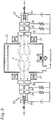
- Fig. 2 shows a deposition apparatus 1a according to a second embodiment of the present invention.
- the same component as that in the first embodiment is marked with the same reference, and a duplicated description is omitted.
- a plasma gun 3a in this embodiment has a pair of upper and lower sheet-like magnets 15 in front of the converging coil 10, that is, beside the chamber 2.
- the sheet-like magnets 15 are arranged so that magnetic poles whose polarity is the same as that of the pole of the converging coil 10 on an outlet side are opposed to each other. Thus, they form a magnetic field which rejects the magnetic flux formed by the converging coil 10, and vertically compress the magnetic flux formed by the converging coil 10.
- the magnetic flux formed in the chamber is widely distributed in a horizontal direction, and accordingly, a formation range of the plasma is vertically compressed, and can be spread in the horizontal direction.
- the feedback electrode 9 is connected to a drive circuit 13a in the opposed plasma gun 3. That is, according to this embodiment, each feedback electrode 9 is supplied only from a power supply of the drive circuit 13 in the opposed plasma gun 3. Therefore, the electrons emitted from the one plasma gun 3 reach the feedback electrode 9 of the other plasma gun 3 without turning back in the center of the chamber 2, as shown by dotted lines. As a result, the density of the generated plasma can be more uniformed.
Description
- The present invention relates to a plasma generation apparatus, a deposition apparatus, and a plasma generation method.
- Conventionally, there has been a method known as a plasma assist method by which a chemical reaction of a deposition material is accelerated due to plasma generated in a chamber at the time of deposition. In the plasma assist method, the plasma is normally formed by a plasma gun which injects a discharge gas to form the plasma while emitting electrons to ionize the discharge gas.
- In general, the plasma gun includes a converging coil for forming a magnetic flux to guide the emitted electrons. When the converging coil is provided, the electrons emitted from the plasma gun move while winding around a magnetic field formed by the converging coil, so that the plasma can reach a position far from the plasma gun.
- However, even when the converging coil is used, a range of the plasma that the plasma gun can form is limited. Therefore, in a case where a deposition target body is large on which a deposition target film is to be formed, there is a need to oppositely arrange two plasma guns to form plasma over a wide range as disclosed in
Patent Document 1, for example. -
Fig. 3 shows a deposition apparatus in which plasma guns 22 are oppositely arranged on both sides of achamber 21. The plasma gun 22 is a pressure-gradient type plasma gun and includes acathode 23 for emitting electrons, afirst electrode 24 and asecond electrode 25 for forming voltage gradients, afeedback electrode 26 for collecting the electrons, and aconverging coil 27 for forming a magnetic flux to guide the electrons. Thus, a discharge gas is injected so as to penetrate centers of those components. - In this deposition apparatus, the magnetic fluxes formed by the converging
coils 27 in the opposed plasma guns 22 repel each other. The electrons emitted from the plasma gun 22 travel while winding around the magnetic flux formed by theconverging coil 27, so that they turn back along the repelling magnetic flux and return to eachfeedback electrode 26 as shown by dotted lines in the drawing. Therefore, the electrons are not sufficiently supplied to an intermediate position of the opposed plasma guns 22, and the plasma is low in density at the position, so that an imbalanced discharge region P is formed as shown in the drawing. - Therefore, in a case where the deposition is performed for a large-size panel, a chemical reaction is not sufficiently caused in the center portion because the plasma is low in density there, so that the problem is that a deposition target film is not uniformly formed because the film is poor in adhesiveness or the like.
- Patent Document 1: Japanese Patent Laid-open Publication No.
JP 7-254315 - In view of the above problems, it is an object of the present invention to provide a plasma generation apparatus and a plasma generation method, by which plasma can be uniformly formed over a wide range, and a deposition apparatus capable of uniformly forming a deposition target film.
- In order to solve the above problems, a plasma generation apparatus according to the present invention includes two oppositely arranged plasma guns each injecting a discharge gas to be ionized and having a cathode for emitting electrons, and a converging coil for forming a magnetic flux to guide the emitted electrons, in which polarities of the converging coils with respect to the cathodes in the two plasma guns are opposite to each other.
- According to this configuration, since the magnetic fluxes formed by the converging coils in the opposed plasma guns are integrated with each other, the integrated magnetic flux is formed so as to penetrate both of the plasma guns. Thus, the electrons emitted from the plasma gun can more surely travel straight, so that the plasma density can be prevented from being lowered in the center. Furthermore, when the plasma is used for the deposition, the chemical reaction at the time of the deposition can be uniformly caused over a wide range.
- Furthermore, according to the plasma generation apparatus in the present invention, the plasma gun is a pressure-gradient type plasma gun and includes a first electrode and a second electrode between the cathode and the converging coil, and the second electrode may internally house an electrode internal magnet for forming a magnetic flux having the same direction as the magnetic flux formed by the converging coil.
- According to this configuration, since the magnetic flux formed by the electrode internal magnet and the magnetic flux formed by the converging coil are integrated with each other, the discharge can be stably performed under the condition that the electrons are trapped by the magnetic fluxes inside the plasma gun.
- Furthermore, according to the plasma generation apparatus in the present invention, the two plasma guns may be driven by two drive circuits insulated from each other, respectively.
- According to this configuration, since a discharge amount of the plasma gun can be individually adjusted, the discharge amount of the one plasma gun can be adjusted so as not to become larger due to asymmetry of a space or the like, so that the plasma can be prevented from becoming imbalanced.
- Furthermore, according to the plasma generation apparatus in the present invention, at least one of a position and an angle of the converging coil may be individually adjustable.
- According to this configuration, since imbalance in plasma flow due to the asymmetry of the space or the like can be corrected by adjusting the position and the angle of the converging coil, the plasma can be uniformly generated.
- Furthermore, according to the plasma generation apparatus in the present invention, the plasma gun may include a feedback electrode for collecting the electrons emitted from the cathode, and the feedback electrode may be connected to a circuit in the opposed plasma gun.
- According to this configuration, since the electrons emitted from the one plasma gun are collected in the other plasma gun, so that the electrons can,more surely travel straight, and the plasma density can be uniformed.
- Furthermore, a deposition apparatus according to the present invention has any one of the above plasma generation apparatuses.
- As described above, according to the present invention, the plasma can be uniformly generated over a wide range. Therefore, at the time of the deposition, the chemical reaction is uniformly caused in the deposition material, so that the deposition target film can be uniformly formed even on the large-size deposition target body.
-
-
Fig. 1 is a schematic configuration diagram of a deposition apparatus according to a first embodiment of the present invention. -
Fig. 2 is a schematic configuration diagram of a deposition apparatus according to a second embodiment of the present invention. -
Fig. 3 is a schematic configuration diagram of a conventional deposition apparatus. - Hereinafter, embodiments of the present invention will be described with reference to the drawings.
Fig. 1 shows a configuration of adeposition apparatus 1 according to a first embodiment of the present invention. Thedeposition apparatus 1 includes a chamber 2 whose inside can be evacuated, and a pair of pressure-gradienttype plasma guns 3 each arranged so as to see the inside of the chamber 2 through an opening provided in a side wall on each side of the chamber 2. - A
glass substrate 4 serving as a deposition target body can be held in an upper portion in an inner space of the chamber 2 so that metal is deposited onto its surface, and acrucible 5 for dissolving a deposition material is arranged in a bottom portion in the inner space thereof. Thecrucible 5 is provided with a heater 5a for heating the deposition material. The heater 5a can adopt a DC or AC resistance heating method, and a method using an electron beam as well. - The
plasma gun 3 has acathode 6 for emitting electrons, a first electrode 7 and a second electrode 8 for forming potential gradients along an orbit of the electrons, a feedback electrode 9 for collecting the electrons emitted from thecathode 6, and anconverging coil 10 for forming a magnetic flux for guiding the electrons emitted from thecathode 6. The first electrode 7 is an annular hollow electrode internally housing a first electrodeinternal magnet 11 composed of a permanent magnet. The second electrode is an annular hollow electrode internally housing a second electrodeinternal magnet 12 composed of an air core coil. The components of theplasma gun 3 and theplasma gun 3 are connected to the chamber 2 with a tube made of metal or glass, in order to ensure airtightness. - In addition, each of the two
plasma guns 3 has adrive circuit 13 for applying a discharge voltage to thecathode 6, the first electrode 7, the second electrode 8, and the feedback electrode 9. The twodrive circuits 13 are electrically insulated from each other and can be separately adjusted. Furthermore, each of theplasma guns 3 injects a discharge gas such as argon gas which is ionized and becomes plasma so that the discharge gas penetrates centers of thecathode 6, the first electrode 7, the second electrode 8, the feedback electrode 9, and convergingcoil 10, and theplasma gun 3 has an adjustingvalve 14 for adjusting a flow amount of the injected discharge gas individually. - A DC voltage is applied from a power supply (not shown) to the
converging coil 10 and the second electrodeinternal magnet 12 so that they have the same polarity direction. Each of theconverging coil 10 and the second electrodeinternal magnet 12 is wound so that a current flows around a center axis of theplasma gun 3, and forms a magnetic flux which penetrates an inside of the coil. Thus, the polarity shown in the drawing only shows the direction of a magnetic pole, and it does not mean that a magnetic flux extends from the pole shown in the drawing. - Here, it is to be noted that the polarity of the
converging coil 10 and the electrodeinternal magnet 12 toward thecathode 6 in theright plasma gun 3 is opposite to that in theleft plasma gun 3. That is, all of theconverging coils 10 and the electrodeinternal magnets 12 have the same absolute polarities. More specifically, in the drawing, the S pole is provided on the left side and the N pole is provided on the right side, as a whole. Therefore, the magnetic fluxes formed by theconverging coils 10 and the electrodeinternal magnets 12 on both sides are integrated with each other, so that the integrated magnetic flux is formed so as to linearly penetrate the right andleft plasma guns 3 along the center axes of the right andleft plasma guns 3. - The electrons emitted from the
cathode 6 travel while winding around the magnetic flux going straight between the right andleft plasma guns 3. Thus, as shown by dotted lines in the drawing, the electrons emitted from theplasma guns 3 on both sides repel from each other by coulomb force, and separate from the magnetic flux in a center portion of the chamber 2, and then return to the respective feedback electrodes 9. Since thedrive circuits 13 of the twoplasma guns 3 are insulated from each other, the number of electrons returning to the feedback electrode 9 is the same as that of the electrons emitted from thecathode 6 in thesame plasma gun 3. Thus, the electrons evenly return to each of the feedback electrodes 9, so that there is no imbalance in electron flow in the chamber 2. - When the electrons are emitted and the discharge gas is supplied from the
plasma gun 3 under the condition that the chamber 2 is evacuated, the discharge gas is ionized, and plasma can be generated, or a plasma region P can be formed. According to this embodiment, the electrons are guided to the center of the chamber 2 by the magnetic flux, and the discharge gas becomes the plasma in the center of the chamber 2, so that the generated plasma can be uniformed in density. Furthermore, the electrons emitted from the right and leftplasma guns 3 can flow symmetrically, so that the plasma region P formed in the chamber 2 is bilaterally symmetric. - When the deposition is performed in the
deposition apparatus 1, the deposition material in thecrucible 5 is dissolved by the heater 5a and a reaction gas for causing a chemical reaction with the deposition material is introduced into the chamber 2 under the condition that the plasma region P is formed in the chamber 2. As a result, the deposition material chemically reacts with the reaction gas, and it reaches theglass substrate 4, whereby a film is formed on the surface of theglass substrate 4. In the plasma region P, the chemical reaction between the deposition material and the reaction gas is accelerated by the plasma. As described above, the plasma region P having the uniform plasma density is formed in thedeposition apparatus 1, so that the deposited film can be uniformed with high quality. In addition, the reaction gas may be a plasma CVD gas such as TEOS. The substrate may be made of metal or plastic other than the glass. Furthermore, a shape of the substrate may be a plate, or a hoop material supplied from a roll-to-roll mechanism. - Furthermore, as for the
actual deposition apparatus 1, operations of the right and leftplasma guns 3 could become imbalanced due to asymmetry caused by the shape of the chamber 2 and the evacuation process, an error in structure of theplasma gun 3, and influences of external magnetic field and electric field. In this respect, according to this embodiment, a discharge gas flow rate of theplasma gun 3 can be individually adjusted by the adjustingvalve 14, so that plasma forming abilities of the right and leftplasma guns 3 can be balanced. - Energy of the plasma formed by each
plasma gun 3 depends on a discharge power of theplasma gun 3, that is, depends on a product of a discharge voltage and a discharge current. Therefore, in order to symmetrically form the plasma on right and left sides in thedeposition apparatus 1, output powers of the drive circuits are required to be equal to each other. Table 1 shows experimental examples for making the plasma discharge symmetric in thedeposition apparatus 1.Table 1 Conditions Discharge voltage adjustment Discharge gas flow rate adjustment Plasma gun 1 Plasma gun 2 Plasma gun 1Plasma gun 2 Discharge pressure (Pa) 0.09 0.09 Discharge power (kw) 7.8 7.8 7.8 7.8 Discharge current (A) 120 102 120 120 Discharge voltage (V) 65 76 65 65 Discharge gas (sccm) 30 30 30 38 - The table shows a case where the discharge gas flow rates are equally set in the right and left plasma guns 3 (
plasma guns 1 and 2), and the discharge powers are equalized by adjusting the discharge voltages, and a case where the discharge voltages are equally set in the right and leftplasma guns 3, and the discharge powers are equalized by adjusting the discharge gas flow rates by thecontrol valves 14. - In the case where the discharge powers are equalized with the discharge voltages, kinetic energy of the emitted electrons varies due to a difference in discharge voltage, and in addition, a value of the discharge current, that is, the number of the emitted electrons becomes imbalanced, so that there is a variation in ionized state of the discharge gas. Meanwhile, in the case where the discharge powers are equalized with the discharge gas flow rates, a discharge gas amount varies, but the discharge voltages and the discharge currents of the
plasma guns 3 are equal, respectively, that is, the emitted electron amounts and the kinetic energy are equal, respectively, so that there is no difference in state of the plasma (ionized discharge gas) between the right and left plasma guns. - Thus, as for the
deposition apparatus 1, by equally setting the discharge voltages of the right and leftplasma guns 3 and adjusting the discharge gas flow rates, the discharge currents can be equal to each other, so that the plasma forming abilities of the right and leftplasma guns 3 can be equalized. In addition, as for thedeposition apparatus 1, it is preferable that a position and an angle of the convergingcoil 10 can be individually adjusted, and the operations of the right and leftplasma guns 3 can be balanced. - Next,
Fig. 2 shows adeposition apparatus 1a according to a second embodiment of the present invention. In this embodiment, the same component as that in the first embodiment is marked with the same reference, and a duplicated description is omitted. - A
plasma gun 3a in this embodiment has a pair of upper and lower sheet-like magnets 15 in front of the convergingcoil 10, that is, beside the chamber 2. The sheet-like magnets 15 are arranged so that magnetic poles whose polarity is the same as that of the pole of the convergingcoil 10 on an outlet side are opposed to each other. Thus, they form a magnetic field which rejects the magnetic flux formed by the convergingcoil 10, and vertically compress the magnetic flux formed by the convergingcoil 10. As a result, the magnetic flux formed in the chamber is widely distributed in a horizontal direction, and accordingly, a formation range of the plasma is vertically compressed, and can be spread in the horizontal direction. - Furthermore, according to the
deposition apparatus 1a in this embodiment, the feedback electrode 9 is connected to adrive circuit 13a in theopposed plasma gun 3. That is, according to this embodiment, each feedback electrode 9 is supplied only from a power supply of thedrive circuit 13 in theopposed plasma gun 3. Therefore, the electrons emitted from the oneplasma gun 3 reach the feedback electrode 9 of theother plasma gun 3 without turning back in the center of the chamber 2, as shown by dotted lines. As a result, the density of the generated plasma can be more uniformed. -
- 1, 1a:
- Deposition apparatus
- 2:
- Chamber
- 3:
- Plasma gun
- 4:
- Glass substrate (Deposition target body)
- 5:
- Crucible
- 5a:
- Heater
- 6:
- Cathode
- 7:
- First electrode
- 8:
- Second electrode
- 9:
- Feedback electrode
- 10:
- Converging coil
- 11:
- First electrode internal magnet
- 12:
- Second electrode internal magnet
- 13, 13a:
- Drive circuit
- 14:
- Adjusting valve
- 15:
- Sheet-like magnet
- P:
- Plasma region
Claims (7)
- A plasma generation apparatus comprising two oppositely arranged plasma guns (3) each injecting a discharge gas to be ionized and having a cathode (6) for emitting electrons and a converging coil (10) for forming a magnetic flux to guide the emitted electrons, characterised in that
polarities of the converging coils (10) with respect to the cathodes (6) in the two plasma guns are opposite to each other. - The plasma generation apparatus according to claim 1, wherein
the plasma gun is a pressure-gradient type plasma gun and comprises a first electrode and a second electrode between the cathode and the converging coil, and
the second electrode internally houses an electrode internal magnet for forming a magnetic flux having the same direction as the magnetic flux formed by the converging coil. - The plasma generation apparatus according to claim 1 or 2, wherein
the two plasma guns are driven by two drive circuits insulated from each other, respectively. - The plasma generation apparatus according to any one of claims 1 to 3, wherein
at least one of a position and an angle of the converging coil is individually adjustable. - The plasma generation apparatus according to any one of claims 1 to 4, wherein
the plasma gun comprises a feedback electrode for collecting the electrons emitted from the cathode, and the feedback electrode is connected to a circuit in the opposed plasma gun. - A deposition apparatus comprising the plasma generation apparatus according to any one of claims 1 to 5.
- A plasma generation method comprising steps of:oppositely arranging two plasma guns each injecting a discharge gas to be ionized and comprising a cathode for emitting electrons, and a converging coil for forming a magnetic flux to guide the emitted electrons;setting polarities of the converging coils with respect to the cathodes in the two plasma guns to be opposite to each other; andadjusting an injected amount of the discharge gas of at least one of the two plasma guns under the condition that discharge voltages of the two plasma guns are equally set to equalize discharge currents of the two plasma guns.
Applications Claiming Priority (2)
| Application Number | Priority Date | Filing Date | Title |
|---|---|---|---|
| JP2012090921A JP5700695B2 (en) | 2012-04-12 | 2012-04-12 | Plasma generating apparatus, vapor deposition apparatus, and plasma generating method |
| PCT/JP2013/055231 WO2013153865A1 (en) | 2012-04-12 | 2013-02-27 | Plasma generation device, vapor deposition device, and plasma generation method |
Publications (3)
| Publication Number | Publication Date |
|---|---|
| EP2838323A1 EP2838323A1 (en) | 2015-02-18 |
| EP2838323A4 EP2838323A4 (en) | 2015-09-23 |
| EP2838323B1 true EP2838323B1 (en) | 2017-11-15 |
Family
ID=49327444
Family Applications (1)
| Application Number | Title | Priority Date | Filing Date |
|---|---|---|---|
| EP13775531.0A Not-in-force EP2838323B1 (en) | 2012-04-12 | 2013-02-27 | Plasma generation device, vapor deposition device, and plasma generation method |
Country Status (7)
| Country | Link |
|---|---|
| US (1) | US9824867B2 (en) |
| EP (1) | EP2838323B1 (en) |
| JP (1) | JP5700695B2 (en) |
| KR (1) | KR101953946B1 (en) |
| CN (1) | CN104221477B (en) |
| TW (1) | TWI558275B (en) |
| WO (1) | WO2013153865A1 (en) |
Families Citing this family (1)
| Publication number | Priority date | Publication date | Assignee | Title |
|---|---|---|---|---|
| KR20180066575A (en) * | 2016-12-09 | 2018-06-19 | (주)트리플코어스코리아 | Anode structure for plasma torch using arc discharge and plasma torch with the same |
Family Cites Families (18)
| Publication number | Priority date | Publication date | Assignee | Title |
|---|---|---|---|---|
| US4863581A (en) * | 1987-02-12 | 1989-09-05 | Kawasaki Steel Corp. | Hollow cathode gun and deposition device for ion plating process |
| JP2898652B2 (en) * | 1988-06-23 | 1999-06-02 | 川崎製鉄株式会社 | Evaporator for ion plating |
| US5009743A (en) * | 1989-11-06 | 1991-04-23 | Gatan Incorporated | Chemically-assisted ion beam milling system for the preparation of transmission electron microscope specimens |
| JPH073442A (en) * | 1993-06-16 | 1995-01-06 | Asahi Glass Co Ltd | Vapor deposition device |
| JPH07254315A (en) * | 1994-03-14 | 1995-10-03 | Nippon Sheet Glass Co Ltd | Formation of film |
| JP2874548B2 (en) * | 1994-03-25 | 1999-03-24 | 日本板硝子株式会社 | Method for forming coating by arc discharge plasma |
| JP2955916B2 (en) * | 1994-06-02 | 1999-10-04 | 住友重機械工業株式会社 | Sheet plasma forming method and apparatus |
| US6103074A (en) * | 1998-02-14 | 2000-08-15 | Phygen, Inc. | Cathode arc vapor deposition method and apparatus |
| JP4287936B2 (en) * | 1999-02-01 | 2009-07-01 | 中外炉工業株式会社 | Vacuum deposition system |
| DE19824077A1 (en) * | 1998-05-29 | 1999-12-02 | Leybold Systems Gmbh | Device for generating plasma |
| WO2002086932A1 (en) * | 2001-04-20 | 2002-10-31 | Applied Process Technologies | Magnetic mirror plasma source |
| JPWO2002098812A1 (en) * | 2001-06-04 | 2004-09-16 | 日本板硝子株式会社 | Method for manufacturing transparent substrate, transparent substrate, and organic electroluminescence device having the transparent substrate |
| JP5080977B2 (en) * | 2005-12-06 | 2012-11-21 | 新明和工業株式会社 | Sheet plasma deposition system |
| JP4906331B2 (en) * | 2005-12-06 | 2012-03-28 | 新明和工業株式会社 | Sheet plasma deposition system |
| US20110011734A1 (en) | 2006-03-01 | 2011-01-20 | Shinmaywa Industries, Ltd. | Plasma Gun and Plasma Gun Deposition System Including the Same |
| WO2008136130A1 (en) | 2007-04-24 | 2008-11-13 | Canon Anelva Corporation | Plasma generation device, and method and apparatus for forming film using the same |
| JP4901696B2 (en) * | 2007-11-06 | 2012-03-21 | キヤノンアネルバ株式会社 | Deposition equipment |
| CN202072760U (en) * | 2011-04-26 | 2011-12-14 | 中国科学院金属研究所 | Arc ion plating device |
-
2012
- 2012-04-12 JP JP2012090921A patent/JP5700695B2/en not_active Expired - Fee Related
-
2013
- 2013-02-27 KR KR1020147027089A patent/KR101953946B1/en active IP Right Grant
- 2013-02-27 EP EP13775531.0A patent/EP2838323B1/en not_active Not-in-force
- 2013-02-27 US US14/391,499 patent/US9824867B2/en not_active Expired - Fee Related
- 2013-02-27 WO PCT/JP2013/055231 patent/WO2013153865A1/en active Application Filing
- 2013-02-27 CN CN201380019358.2A patent/CN104221477B/en not_active Expired - Fee Related
- 2013-04-01 TW TW102111671A patent/TWI558275B/en not_active IP Right Cessation
Non-Patent Citations (1)
| Title |
|---|
| None * |
Also Published As
| Publication number | Publication date |
|---|---|
| US20150107987A1 (en) | 2015-04-23 |
| EP2838323A4 (en) | 2015-09-23 |
| WO2013153865A1 (en) | 2013-10-17 |
| EP2838323A1 (en) | 2015-02-18 |
| CN104221477B (en) | 2016-11-23 |
| KR20140143373A (en) | 2014-12-16 |
| TWI558275B (en) | 2016-11-11 |
| TW201349945A (en) | 2013-12-01 |
| JP5700695B2 (en) | 2015-04-15 |
| CN104221477A (en) | 2014-12-17 |
| KR101953946B1 (en) | 2019-03-04 |
| JP2013218985A (en) | 2013-10-24 |
| US9824867B2 (en) | 2017-11-21 |
Similar Documents
| Publication | Publication Date | Title |
|---|---|---|
| US6211622B1 (en) | Plasma processing equipment | |
| US9564297B2 (en) | Electron beam plasma source with remote radical source | |
| US8778151B2 (en) | Plasma processing apparatus | |
| CN1953129B (en) | Method of operating ion source and ion implanting apparatus | |
| CN109906496A (en) | RF ion source with dynamic volume control | |
| JP4660570B2 (en) | Vacuum film forming apparatus and film forming method | |
| US20100012033A1 (en) | Sheet Plasma Film Forming Apparatus | |
| US20090114154A1 (en) | Plasma treatment apparatus | |
| EP2838323B1 (en) | Plasma generation device, vapor deposition device, and plasma generation method | |
| KR101043166B1 (en) | Plasma film deposition system and method for producing film | |
| US20090159441A1 (en) | Plasma Film Deposition System | |
| CN108885964B (en) | Plasma processing equipment capable of adjusting electric charge quantity | |
| US3801719A (en) | Emitter block assembly | |
| JP2003264098A (en) | Sheet plasma treatment apparatus | |
| JP2008038197A (en) | Plasma film deposition apparatus | |
| KR20200051947A (en) | Sputtering apparatus | |
| JP5271145B2 (en) | Plasma deposition system | |
| CN111133551B (en) | Ion source device | |
| CH702969A2 (en) | Apparatus for treating and/or coating glass surfaces with thin layers using plasma, comprises anode segments, and a magnetic assembly, where the segment is based on magnetic field that forces electrons to sputter cathode | |
| KR101556830B1 (en) | Inductively coupled plasma source for improving sputter yield and apparatus for sputtering using the same | |
| JP2013241652A (en) | Film deposition apparatus |
Legal Events
| Date | Code | Title | Description |
|---|---|---|---|
| PUAI | Public reference made under article 153(3) epc to a published international application that has entered the european phase |
Free format text: ORIGINAL CODE: 0009012 |
|
| 17P | Request for examination filed |
Effective date: 20141009 |
|
| AK | Designated contracting states |
Kind code of ref document: A1 Designated state(s): AL AT BE BG CH CY CZ DE DK EE ES FI FR GB GR HR HU IE IS IT LI LT LU LV MC MK MT NL NO PL PT RO RS SE SI SK SM TR |
|
| AX | Request for extension of the european patent |
Extension state: BA ME |
|
| DAX | Request for extension of the european patent (deleted) | ||
| RA4 | Supplementary search report drawn up and despatched (corrected) |
Effective date: 20150824 |
|
| RIC1 | Information provided on ipc code assigned before grant |
Ipc: C23C 14/35 20060101ALI20150818BHEP Ipc: H05H 1/50 20060101AFI20150818BHEP Ipc: C23C 14/32 20060101ALI20150818BHEP Ipc: H05H 1/14 20060101ALI20150818BHEP Ipc: H05H 1/46 20060101ALI20150818BHEP Ipc: H01J 37/32 20060101ALI20150818BHEP Ipc: H01J 37/34 20060101ALI20150818BHEP |
|
| GRAP | Despatch of communication of intention to grant a patent |
Free format text: ORIGINAL CODE: EPIDOSNIGR1 |
|
| INTG | Intention to grant announced |
Effective date: 20170609 |
|
| GRAS | Grant fee paid |
Free format text: ORIGINAL CODE: EPIDOSNIGR3 |
|
| GRAA | (expected) grant |
Free format text: ORIGINAL CODE: 0009210 |
|
| AK | Designated contracting states |
Kind code of ref document: B1 Designated state(s): AL AT BE BG CH CY CZ DE DK EE ES FI FR GB GR HR HU IE IS IT LI LT LU LV MC MK MT NL NO PL PT RO RS SE SI SK SM TR |
|
| REG | Reference to a national code |
Ref country code: CH Ref legal event code: EP Ref country code: GB Ref legal event code: FG4D Ref country code: AT Ref legal event code: REF Ref document number: 947486 Country of ref document: AT Kind code of ref document: T Effective date: 20171115 |
|
| REG | Reference to a national code |
Ref country code: IE Ref legal event code: FG4D |
|
| REG | Reference to a national code |
Ref country code: DE Ref legal event code: R096 Ref document number: 602013029524 Country of ref document: DE |
|
| REG | Reference to a national code |
Ref country code: FR Ref legal event code: PLFP Year of fee payment: 6 |
|
| REG | Reference to a national code |
Ref country code: NL Ref legal event code: MP Effective date: 20171115 |
|
| REG | Reference to a national code |
Ref country code: LT Ref legal event code: MG4D |
|
| REG | Reference to a national code |
Ref country code: AT Ref legal event code: MK05 Ref document number: 947486 Country of ref document: AT Kind code of ref document: T Effective date: 20171115 |
|
| PG25 | Lapsed in a contracting state [announced via postgrant information from national office to epo] |
Ref country code: FI Free format text: LAPSE BECAUSE OF FAILURE TO SUBMIT A TRANSLATION OF THE DESCRIPTION OR TO PAY THE FEE WITHIN THE PRESCRIBED TIME-LIMIT Effective date: 20171115 Ref country code: ES Free format text: LAPSE BECAUSE OF FAILURE TO SUBMIT A TRANSLATION OF THE DESCRIPTION OR TO PAY THE FEE WITHIN THE PRESCRIBED TIME-LIMIT Effective date: 20171115 Ref country code: NO Free format text: LAPSE BECAUSE OF FAILURE TO SUBMIT A TRANSLATION OF THE DESCRIPTION OR TO PAY THE FEE WITHIN THE PRESCRIBED TIME-LIMIT Effective date: 20180215 Ref country code: SE Free format text: LAPSE BECAUSE OF FAILURE TO SUBMIT A TRANSLATION OF THE DESCRIPTION OR TO PAY THE FEE WITHIN THE PRESCRIBED TIME-LIMIT Effective date: 20171115 Ref country code: LT Free format text: LAPSE BECAUSE OF FAILURE TO SUBMIT A TRANSLATION OF THE DESCRIPTION OR TO PAY THE FEE WITHIN THE PRESCRIBED TIME-LIMIT Effective date: 20171115 Ref country code: NL Free format text: LAPSE BECAUSE OF FAILURE TO SUBMIT A TRANSLATION OF THE DESCRIPTION OR TO PAY THE FEE WITHIN THE PRESCRIBED TIME-LIMIT Effective date: 20171115 |
|
| PG25 | Lapsed in a contracting state [announced via postgrant information from national office to epo] |
Ref country code: HR Free format text: LAPSE BECAUSE OF FAILURE TO SUBMIT A TRANSLATION OF THE DESCRIPTION OR TO PAY THE FEE WITHIN THE PRESCRIBED TIME-LIMIT Effective date: 20171115 Ref country code: RS Free format text: LAPSE BECAUSE OF FAILURE TO SUBMIT A TRANSLATION OF THE DESCRIPTION OR TO PAY THE FEE WITHIN THE PRESCRIBED TIME-LIMIT Effective date: 20171115 Ref country code: LV Free format text: LAPSE BECAUSE OF FAILURE TO SUBMIT A TRANSLATION OF THE DESCRIPTION OR TO PAY THE FEE WITHIN THE PRESCRIBED TIME-LIMIT Effective date: 20171115 Ref country code: GR Free format text: LAPSE BECAUSE OF FAILURE TO SUBMIT A TRANSLATION OF THE DESCRIPTION OR TO PAY THE FEE WITHIN THE PRESCRIBED TIME-LIMIT Effective date: 20180216 Ref country code: BG Free format text: LAPSE BECAUSE OF FAILURE TO SUBMIT A TRANSLATION OF THE DESCRIPTION OR TO PAY THE FEE WITHIN THE PRESCRIBED TIME-LIMIT Effective date: 20180215 Ref country code: AT Free format text: LAPSE BECAUSE OF FAILURE TO SUBMIT A TRANSLATION OF THE DESCRIPTION OR TO PAY THE FEE WITHIN THE PRESCRIBED TIME-LIMIT Effective date: 20171115 |
|
| PG25 | Lapsed in a contracting state [announced via postgrant information from national office to epo] |
Ref country code: CZ Free format text: LAPSE BECAUSE OF FAILURE TO SUBMIT A TRANSLATION OF THE DESCRIPTION OR TO PAY THE FEE WITHIN THE PRESCRIBED TIME-LIMIT Effective date: 20171115 Ref country code: CY Free format text: LAPSE BECAUSE OF FAILURE TO SUBMIT A TRANSLATION OF THE DESCRIPTION OR TO PAY THE FEE WITHIN THE PRESCRIBED TIME-LIMIT Effective date: 20171115 Ref country code: EE Free format text: LAPSE BECAUSE OF FAILURE TO SUBMIT A TRANSLATION OF THE DESCRIPTION OR TO PAY THE FEE WITHIN THE PRESCRIBED TIME-LIMIT Effective date: 20171115 Ref country code: DK Free format text: LAPSE BECAUSE OF FAILURE TO SUBMIT A TRANSLATION OF THE DESCRIPTION OR TO PAY THE FEE WITHIN THE PRESCRIBED TIME-LIMIT Effective date: 20171115 Ref country code: SK Free format text: LAPSE BECAUSE OF FAILURE TO SUBMIT A TRANSLATION OF THE DESCRIPTION OR TO PAY THE FEE WITHIN THE PRESCRIBED TIME-LIMIT Effective date: 20171115 |
|
| REG | Reference to a national code |
Ref country code: DE Ref legal event code: R097 Ref document number: 602013029524 Country of ref document: DE |
|
| PG25 | Lapsed in a contracting state [announced via postgrant information from national office to epo] |
Ref country code: RO Free format text: LAPSE BECAUSE OF FAILURE TO SUBMIT A TRANSLATION OF THE DESCRIPTION OR TO PAY THE FEE WITHIN THE PRESCRIBED TIME-LIMIT Effective date: 20171115 Ref country code: IT Free format text: LAPSE BECAUSE OF FAILURE TO SUBMIT A TRANSLATION OF THE DESCRIPTION OR TO PAY THE FEE WITHIN THE PRESCRIBED TIME-LIMIT Effective date: 20171115 Ref country code: PL Free format text: LAPSE BECAUSE OF FAILURE TO SUBMIT A TRANSLATION OF THE DESCRIPTION OR TO PAY THE FEE WITHIN THE PRESCRIBED TIME-LIMIT Effective date: 20171115 Ref country code: SM Free format text: LAPSE BECAUSE OF FAILURE TO SUBMIT A TRANSLATION OF THE DESCRIPTION OR TO PAY THE FEE WITHIN THE PRESCRIBED TIME-LIMIT Effective date: 20171115 |
|
| REG | Reference to a national code |
Ref country code: CH Ref legal event code: PL |
|
| PLBE | No opposition filed within time limit |
Free format text: ORIGINAL CODE: 0009261 |
|
| STAA | Information on the status of an ep patent application or granted ep patent |
Free format text: STATUS: NO OPPOSITION FILED WITHIN TIME LIMIT |
|
| PG25 | Lapsed in a contracting state [announced via postgrant information from national office to epo] |
Ref country code: MC Free format text: LAPSE BECAUSE OF FAILURE TO SUBMIT A TRANSLATION OF THE DESCRIPTION OR TO PAY THE FEE WITHIN THE PRESCRIBED TIME-LIMIT Effective date: 20171115 |
|
| 26N | No opposition filed |
Effective date: 20180817 |
|
| REG | Reference to a national code |
Ref country code: BE Ref legal event code: MM Effective date: 20180228 |
|
| PG25 | Lapsed in a contracting state [announced via postgrant information from national office to epo] |
Ref country code: LU Free format text: LAPSE BECAUSE OF NON-PAYMENT OF DUE FEES Effective date: 20180227 Ref country code: CH Free format text: LAPSE BECAUSE OF NON-PAYMENT OF DUE FEES Effective date: 20180228 Ref country code: SI Free format text: LAPSE BECAUSE OF FAILURE TO SUBMIT A TRANSLATION OF THE DESCRIPTION OR TO PAY THE FEE WITHIN THE PRESCRIBED TIME-LIMIT Effective date: 20171115 Ref country code: LI Free format text: LAPSE BECAUSE OF NON-PAYMENT OF DUE FEES Effective date: 20180228 |
|
| REG | Reference to a national code |
Ref country code: IE Ref legal event code: MM4A |
|
| PG25 | Lapsed in a contracting state [announced via postgrant information from national office to epo] |
Ref country code: IE Free format text: LAPSE BECAUSE OF NON-PAYMENT OF DUE FEES Effective date: 20180227 |
|
| PG25 | Lapsed in a contracting state [announced via postgrant information from national office to epo] |
Ref country code: BE Free format text: LAPSE BECAUSE OF NON-PAYMENT OF DUE FEES Effective date: 20180228 |
|
| PG25 | Lapsed in a contracting state [announced via postgrant information from national office to epo] |
Ref country code: MT Free format text: LAPSE BECAUSE OF NON-PAYMENT OF DUE FEES Effective date: 20180227 |
|
| PGFP | Annual fee paid to national office [announced via postgrant information from national office to epo] |
Ref country code: FR Payment date: 20191216 Year of fee payment: 8 |
|
| PG25 | Lapsed in a contracting state [announced via postgrant information from national office to epo] |
Ref country code: TR Free format text: LAPSE BECAUSE OF FAILURE TO SUBMIT A TRANSLATION OF THE DESCRIPTION OR TO PAY THE FEE WITHIN THE PRESCRIBED TIME-LIMIT Effective date: 20171115 |
|
| PGFP | Annual fee paid to national office [announced via postgrant information from national office to epo] |
Ref country code: GB Payment date: 20200219 Year of fee payment: 8 |
|
| PG25 | Lapsed in a contracting state [announced via postgrant information from national office to epo] |
Ref country code: PT Free format text: LAPSE BECAUSE OF FAILURE TO SUBMIT A TRANSLATION OF THE DESCRIPTION OR TO PAY THE FEE WITHIN THE PRESCRIBED TIME-LIMIT Effective date: 20171115 |
|
| PG25 | Lapsed in a contracting state [announced via postgrant information from national office to epo] |
Ref country code: HU Free format text: LAPSE BECAUSE OF FAILURE TO SUBMIT A TRANSLATION OF THE DESCRIPTION OR TO PAY THE FEE WITHIN THE PRESCRIBED TIME-LIMIT; INVALID AB INITIO Effective date: 20130227 Ref country code: MK Free format text: LAPSE BECAUSE OF NON-PAYMENT OF DUE FEES Effective date: 20171115 |
|
| PG25 | Lapsed in a contracting state [announced via postgrant information from national office to epo] |
Ref country code: AL Free format text: LAPSE BECAUSE OF FAILURE TO SUBMIT A TRANSLATION OF THE DESCRIPTION OR TO PAY THE FEE WITHIN THE PRESCRIBED TIME-LIMIT Effective date: 20171115 Ref country code: IS Free format text: LAPSE BECAUSE OF FAILURE TO SUBMIT A TRANSLATION OF THE DESCRIPTION OR TO PAY THE FEE WITHIN THE PRESCRIBED TIME-LIMIT Effective date: 20180315 |
|
| PGFP | Annual fee paid to national office [announced via postgrant information from national office to epo] |
Ref country code: DE Payment date: 20200427 Year of fee payment: 8 |
|
| REG | Reference to a national code |
Ref country code: DE Ref legal event code: R119 Ref document number: 602013029524 Country of ref document: DE |
|
| GBPC | Gb: european patent ceased through non-payment of renewal fee |
Effective date: 20210227 |
|
| PG25 | Lapsed in a contracting state [announced via postgrant information from national office to epo] |
Ref country code: DE Free format text: LAPSE BECAUSE OF NON-PAYMENT OF DUE FEES Effective date: 20210901 Ref country code: GB Free format text: LAPSE BECAUSE OF NON-PAYMENT OF DUE FEES Effective date: 20210227 Ref country code: FR Free format text: LAPSE BECAUSE OF NON-PAYMENT OF DUE FEES Effective date: 20210228 |