EP2838220B1 - Method for the redundant transmission of messages in an industrial communication network and communication device - Google Patents
Method for the redundant transmission of messages in an industrial communication network and communication device Download PDFInfo
- Publication number
- EP2838220B1 EP2838220B1 EP13180335.5A EP13180335A EP2838220B1 EP 2838220 B1 EP2838220 B1 EP 2838220B1 EP 13180335 A EP13180335 A EP 13180335A EP 2838220 B1 EP2838220 B1 EP 2838220B1
- Authority
- EP
- European Patent Office
- Prior art keywords
- network
- messages
- communication device
- signal processing
- processing unit
- Prior art date
- Legal status (The legal status is an assumption and is not a legal conclusion. Google has not performed a legal analysis and makes no representation as to the accuracy of the status listed.)
- Active
Links
- 238000004891 communication Methods 0.000 title claims description 134
- 230000005540 biological transmission Effects 0.000 title claims description 28
- 238000000034 method Methods 0.000 title claims description 28
- 238000012545 processing Methods 0.000 claims description 41
- 230000008878 coupling Effects 0.000 claims description 29
- 238000010168 coupling process Methods 0.000 claims description 29
- 238000005859 coupling reaction Methods 0.000 claims description 29
- 230000006870 function Effects 0.000 claims description 16
- 230000010076 replication Effects 0.000 claims description 4
- 238000004519 manufacturing process Methods 0.000 description 3
- 238000001514 detection method Methods 0.000 description 2
- 238000011161 development Methods 0.000 description 2
- 230000018109 developmental process Effects 0.000 description 2
- 230000008030 elimination Effects 0.000 description 2
- 238000003379 elimination reaction Methods 0.000 description 2
- 241001074707 Eucalyptus polyanthemos Species 0.000 description 1
- 230000001419 dependent effect Effects 0.000 description 1
- 230000003090 exacerbative effect Effects 0.000 description 1
- 239000000284 extract Substances 0.000 description 1
- 238000003780 insertion Methods 0.000 description 1
- 230000037431 insertion Effects 0.000 description 1
- 230000007257 malfunction Effects 0.000 description 1
- 239000011159 matrix material Substances 0.000 description 1
- 238000004801 process automation Methods 0.000 description 1
Images

Classifications
-
- H—ELECTRICITY
- H04—ELECTRIC COMMUNICATION TECHNIQUE
- H04L—TRANSMISSION OF DIGITAL INFORMATION, e.g. TELEGRAPHIC COMMUNICATION
- H04L12/00—Data switching networks
- H04L12/28—Data switching networks characterised by path configuration, e.g. LAN [Local Area Networks] or WAN [Wide Area Networks]
- H04L12/46—Interconnection of networks
- H04L12/4641—Virtual LANs, VLANs, e.g. virtual private networks [VPN]
-
- H—ELECTRICITY
- H04—ELECTRIC COMMUNICATION TECHNIQUE
- H04L—TRANSMISSION OF DIGITAL INFORMATION, e.g. TELEGRAPHIC COMMUNICATION
- H04L1/00—Arrangements for detecting or preventing errors in the information received
- H04L1/08—Arrangements for detecting or preventing errors in the information received by repeating transmission, e.g. Verdan system
-
- H—ELECTRICITY
- H04—ELECTRIC COMMUNICATION TECHNIQUE
- H04L—TRANSMISSION OF DIGITAL INFORMATION, e.g. TELEGRAPHIC COMMUNICATION
- H04L1/00—Arrangements for detecting or preventing errors in the information received
- H04L1/22—Arrangements for detecting or preventing errors in the information received using redundant apparatus to increase reliability
-
- H—ELECTRICITY
- H04—ELECTRIC COMMUNICATION TECHNIQUE
- H04L—TRANSMISSION OF DIGITAL INFORMATION, e.g. TELEGRAPHIC COMMUNICATION
- H04L41/00—Arrangements for maintenance, administration or management of data switching networks, e.g. of packet switching networks
- H04L41/12—Discovery or management of network topologies
-
- H—ELECTRICITY
- H04—ELECTRIC COMMUNICATION TECHNIQUE
- H04L—TRANSMISSION OF DIGITAL INFORMATION, e.g. TELEGRAPHIC COMMUNICATION
- H04L45/00—Routing or path finding of packets in data switching networks
- H04L45/24—Multipath
Definitions
- An industrial automation system usually comprises a large number of industrial automation devices that are networked with one another via an industrial communication network and are used in the context of manufacturing or process automation to control or regulate systems, machines or devices. Due to time-critical framework conditions in technical systems that are automated by means of industrial automation devices, real-time communication protocols such as Profinet, Profibus or Real-Time Ethernet are predominantly used in industrial communication networks for communication between automation devices.
- real-time communication protocols such as Profinet, Profibus or Real-Time Ethernet are predominantly used in industrial communication networks for communication between automation devices.
- Interruptions in communication connections between computer units of an industrial automation system or industrial automation devices are extremely problematic, since, in addition to a loss of information, this can lead, for example, to an undesired or unnecessary repetition of a transmission of a service request. This causes an additional load on the communication connections of the industrial automation system, which can lead to further system malfunctions or errors.
- messages that are not or not completely transmitted can, for example, prevent an industrial automation system from transitioning to or remaining in a safe operating state. In the worst case scenario, a complete production plant can fail and lead to an expensive production downtime.
- a particular problem regularly results from message traffic relatively many, but relatively short messages, thereby exacerbating the above problems.
- communication protocols such as Media Redundancy Protocol, High-availability Seamless Redundancy, Parallel Redundancy Protocol or (Rapid) Spanning Tree Protocol have been developed for high-availability, redundantly operable in industrial communication networks.
- MRP Media Redundancy Protocol
- IEC 62439 standard and enables compensation of individual connection failures in networks with a simple ring topology in the event of bursty redundant transmission of messages. Intermittent media redundancy processes can basically be implemented with relatively little effort.
- messages can be lost in the event of an error and, on the other hand, a fault condition is initially present during a reconfiguration of a communication network.
- a fault condition must be secured by a superimposed communication protocol, for example by means of TCP / IP at the switching or transport layer level, in order to avoid an interruption of a communication connection.
- High-availability Seamless Redundancy (HSR) and Parallel Redundancy Protocol (PRP) are defined in the IEC 62439-3 standard and enable bumpless redundant transmission of messages, in particular without switching surges in the event of topology changes.
- HSR High-availability Seamless Redundancy
- PRP Parallel Redundancy Protocol
- each message is duplicated by a sending communication device and sent to a recipient in two different ways.
- a receiver-side communication device creates duplicates representing redundant messages are filtered out from a received data stream.
- a network component that provides access to the redundant communication network can assume different roles.
- Such a network component which transmits telegrams between participants or end devices in an HSR or PRP communication network on the one hand and end devices or network segments without HSR / PRP functionality on the other hand, is referred to as an HSR / PRP proxy or RedBox.
- a network component for access to a redundant HSR or PRP communication network can connect several HSR rings or implement communication between HSR and PRP network segments. In this case the network component is referred to as an HSR-HSR coupler or QuadBox or HSR-PRP coupler.
- a method for operating a network which has a switch and network infrastructure devices connected to it.
- the switch is controlled by a control unit.
- a redundancy unit connected between the switch and the control unit analyzes a data stream between the switch and the control unit and, depending on an analysis result, inserts data into the data stream or removes data from the data stream.
- EP 2 282 452 A1 describes a method for data transmission within a ring-like communication network, in which the data transmission takes place in accordance with high-availability seamless redundancy and the communication network comprises at least one master node, one source node and one destination node.
- Each node has a first and a second communication interface with a respective first and second neighboring node.
- every node receives Data frame via the first communication interface and forwards the received data frame either changed or unchanged via the second communication interface without additional delay.
- the master node sends a first and second redundant data frame or an empty data frame to its first or second neighboring node.
- the source node fills the respective data frame in a predetermined reserved area with process data.
- Each filled data frame is then immediately and individually forwarded to the first or second neighboring node of the source node.
- the destination node finally extracts the process data from the first received filled data frame of a pair of redundant data frames.
- a method for redundant communication is known in a communication system which comprises a plurality of communication networks.
- the communication networks are connected to one another via at least one coupling node.
- a retransmission of data originating from a first communication network from a second communication network back into the first communication network is prevented on the basis of information defined before the data transmission.
- Seamless Redundancy or Parallel Redundancy Protocol are limited in their application to network topologies with ring structures or with several redundant communication networks set up separately from one another.
- the present invention is based on the object of an essentially topology-independent method for redundant, bumpless message transmission in a meshed industrial environment To create a communication network and to specify a communication device suitable for carrying out the method.
- At least one communication device comprises at least a first and a second transmitting and receiving unit, each of which has an interface for a network connection of the industrial communication network and is connected to a coupling element of the communication device.
- This communication device is a switch or a bridge.
- the coupling element is preferably a high-speed bus.
- the coupling element can in principle also be implemented by means of a matrix switching network.
- a signal processing unit of the communication device is assigned to the sending and receiving units, by means of which messages to be sent redundantly by the communication device are sent duplicated by the sending and receiving units and messages received redundantly by the sending and receiving units on the communication device are detected.
- a message can be represented by a data segment, a data packet or a data frame, for example. Messages that are redundant to one another are identified according to the invention by a common duplicate identifier.
- the industrial communication network has any meshed network topology.
- a communication network with a meshed network topology comprises, for example, several paths between two network nodes that are routed via separate coupling units, such as switches or bridges, and coupling links, such as wired or wired communication links.
- mutually independent paths are determined which include separate network nodes. Messages with duplicate identifiers are exchanged between the transmitting and receiving units of the communication device in accordance with forwarding rules corresponding to the determined paths. In this way, seamless media redundancy can be implemented in a single communication network with any meshed network topology.
- a simply connected network node is connected to the transmitting and receiving units via the coupling element.
- the duplicate identifiers are inserted into messages to be sent redundantly by the network node that is simply connected.
- duplicate identifiers are removed from redundantly received messages by the simply connected network node.
- the duplicate identifiers can be inserted by the signal processing unit in messages to be sent redundantly from the simply connected network node and removed from redundantly received messages for the simply connected network node.
- Messages exchanged in a communication relationship on a determined path can be uniquely identified using the source and destination address, a defined priority or an identifier of a virtual local network or a combination of these details.
- Source and destination addresses can be both IP addresses and MAC addresses.
- VLANs logical groupings of communication participants or connections, referred to as VLANs, are to be subsumed under virtual local networks.
- a virtual local network is set up in each case for the mutually independent paths determined.
- the mutually independent paths determined are identified using an identifier of their assigned virtual local network.
- a virtual local network can be set up in a port-based or dynamic manner.
- the signal processing unit of the communication device is preferably implemented by means of a field programmable gate array (FPGA), while the coupling element is, for example, a backplane switch with an assigned controller.
- FPGA field programmable gate array
- an FPGA can act as a coprocessor for a backplane switch controller. Since backplane switch controllers usually have a VLAN functionality, the connection of an FPGA as a coprocessor for a backplane switch can be simplified. This is because the FPGA can use the respective VLAN identifiers in data frames to send messages according to the determined independent messages Treat paths differently.
- an FPGA can be used to store a table (proxy node table) with information on all of the simply connected network nodes connected to the coupling element. This enables simple management of simply connected network nodes connected to the communication device.
- the mutually independent paths can be determined, for example, by a central instance within the industrial communication network or in a decentralized manner by the network nodes of the industrial communication network.
- the mutually independent paths can be determined by the signal processing unit of the communication device.
- Duplicate identifiers of messages that have already been received without errors are preferably stored in a memory unit assigned to the signal processing unit. Accordingly, when a new message is received, the signal processing unit checks its duplicate identifier for correspondence with an already stored duplicate identifier.
- a coupling element connected to the transmitting and receiving units is provided.
- a signal processing unit is assigned to the sending and receiving units, which has a replication unit for duplicating messages to be sent redundantly by the sending and receiving units comprises a filter unit which is set up for a detection of redundantly received messages. Messages that are redundant to one another are identified by a common duplicate identifier.
- the communication device is designed and set up for operation in an industrial communication network with a meshed network topology. For an at least partially redundant communication connection between two network nodes within the industrial communication network, mutually independent paths are determined which include separate network nodes.
- the signal processing unit comprises a forwarding unit which is designed and set up so that messages with duplicate identifiers are exchanged between the transmitting and receiving units of the communication device in accordance with forwarding rules corresponding to the determined paths.
- a simply connected network node can be connected to the transmitting and receiving units via the coupling element.
- the signal processing unit can comprise a functional unit which is designed and set up so that duplicate identifiers are inserted by the signal processing unit into messages of the simply connected network node that are to be sent redundantly.
- the signal processing unit can comprise a functional unit which is designed and set up so that duplicate identifiers are removed by the redundantly received messages for the simply connected network node by the signal processing unit.
- a virtual local network is preferably set up in each case for the mutually independent paths determined.
- the determined paths that are independent of one another can be identified using an identifier of their assigned virtual local network.
- the coupling element comprises a control unit which is set up to operate virtual local networks.
- the signal processing unit is designed and set up to determine the mutually independent paths, for example as a central entity within the industrial communication network.
- the transmitting and receiving units can be connected to the coupling element directly or via the signal processing unit.
- the signal processing unit can in turn be connected to the transmitting and receiving units directly or via the coupling element.
- the signal processing unit comprises a memory unit for storing duplicate identifiers of messages that have already been received without errors.
- the filter unit is designed and set up to check its duplicate identifier for correspondence with an already stored duplicate identifier when a new message is received.
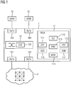
- the communication device 1 shown for an industrial communication network 2 that can be operated redundantly comprises a plurality of transmitting and receiving units 101-104, each of which has an interface for a network connection of the industrial communication network 2.
- a first and a second transmitting and receiving unit 101-102 are connected directly to the industrial communication network 2.
- a coupling element 12 is connected to the transmitting and receiving units 101-104.
- two simply connected network nodes 31-32 are connected to the first 101 and the second transmitting and receiving unit 102 via the coupling element 12.
- the coupling element 12 comprises a control unit 121 which is set up for the operation of virtual local networks.
- the coupling element 12 is preferably implemented by a backplane switch with an integrated controller.
- a signal processing unit 11 implemented by means of a field programmable gate array (FPGA) is assigned to the sending and receiving units 101-104 and comprises a replication unit 111 for duplicating messages to be sent redundantly by the first 101 and the second sending and receiving unit 102.
- the signal processing unit 11 has a filter unit 112 which is set up to detect messages redundantly received by the first 101 and the second transmitting and receiving unit 102. To each other redundant messages are identified by a common duplicate identifier.
- the communication device is designed and set up for operation in an industrial communication network 2 with a meshed network topology. For an at least partially redundant communication connection between two network nodes within the industrial communication network, mutually independent paths are determined which comprise separate network nodes of an individual communication network.
- the signal processing unit also includes a forwarding unit 113, which is designed and set up so that messages with duplicate identifiers are exchanged between the transmitting and receiving units 101-102 of the communication device 1, which are directly connected to the meshed communication network 2, in accordance with forwarding rules corresponding to the determined paths are.
- the forwarding unit 113 can also determine redundant, mutually independent paths in accordance with a possible embodiment variant or provide forwarding rules for communication devices at further network nodes within the industrial communication network 2.
- the signal processing unit 11 includes a memory unit 114 for storing duplicate identifiers of messages that have already been received without errors.
- the filter unit 112 is designed and set up to check its duplicate identifier for correspondence with an already stored duplicate identifier when a new message is received.
- the signal processing unit 11 includes a memory unit 115 for storing a table (proxy node table) with information about all of the simply connected network nodes 31-32 connected to the coupling element 12.
- the signal processing unit 11 comprises as an optional component a functional unit 116 which is designed and set up so that duplicate identifiers are inserted by the signal processing unit 11 into redundant messages of a simply connected network node 31-32.
- the signal processing unit 11 has as an optional component a functional unit 117 which is designed and set up so that duplicate identifiers are removed by the redundantly received messages for a simply connected network node 31-32 by the signal processing unit 11.
- the communication device accordingly Figure 1 is suitable for carrying out a method for redundant message transmission in an industrial communication network 2, in which the industrial communication network has a meshed network topology 2, and in which independent paths are determined for an at least partially redundant communication connection between two network nodes within the industrial communication network, which separate paths Include network nodes of a single communication network.
- the mutually independent paths can be determined both by a central instance within the industrial communication network and in a decentralized manner by the network nodes of the industrial communication network. For example, a virtual local network can be set up in each case for the mutually independent paths determined. The determined are accordingly independent of one another Identified paths based on an identifier of their assigned virtual local network.
- the network nodes 211-214 only implement the basic function FWD and exchange messages with duplicate identifiers according to forwarding rules corresponding to the determined paths between their connections.
- the basic function FWD can be implemented, for example, by switches without redundancy functions.
- the network nodes 201, 204 and 206 represent simply connected end nodes.
- the network node 201 in the present exemplary embodiment does not implement any redundancy functions, while the network nodes 204 and 206 at least implement the basic functions ADD and REM.
- the network node 202 serving as a branching point for the network node 201 realizes all of the above-mentioned basic functions.
- the network nodes 205 and 208 serving as branch points for the network nodes 204 and 206 only have to implement the basic functions CPY, FLT and FWD, since the two simply connected network nodes 204 and 206 already implement basic basic functions.
- network node 204 is connected directly to its assigned branching point.
- the network node 203 provides a duplicate to the in Figure 2 As a result of this, it implements all of the above-mentioned basic functions to carry out the above-described method for redundant message transmission.
Description
Üblicherweise umfaßt ein industrielles Automatisierungssystem eine Vielzahl von industriellen Automatisierungsgeräten, die über ein industrielles Kommunikationsnetz miteinander vernetzt sind und im Rahmen einer Fertigungs- oder Prozeßautomatisierung zur Steuerung oder Regelung von Anlagen, Maschinen bzw. Geräten dienen. Aufgrund zeitkritischer Rahmenbedingungen in technischen Systemen, die mittels industrieller Automatisierungsgeräte automatisiert sind, werden in industriellen Kommunikationsnetzen zur Kommunikation zwischen Automatisierungsgeräten überwiegend Echzeit-Kommunikationsprotokolle, wie Profinet, Profibus oder Real-Time-Ethernet, verwendet.An industrial automation system usually comprises a large number of industrial automation devices that are networked with one another via an industrial communication network and are used in the context of manufacturing or process automation to control or regulate systems, machines or devices. Due to time-critical framework conditions in technical systems that are automated by means of industrial automation devices, real-time communication protocols such as Profinet, Profibus or Real-Time Ethernet are predominantly used in industrial communication networks for communication between automation devices.
Äußerst problematisch sind Unterbrechungen von Kommunikationsverbindungen zwischen Rechnereinheiten eines industriellen Automatisierungssystems oder industriellen Automatisierungsgeräten, da dies neben einem Informationsverlust beispielsweise zu einer unerwünschten oder unnötigen Wiederholung einer Übermittlung einer Dienstanforderung führen kann. Hierdurch wird eine zusätzliche Auslastung von Kommunikationsverbindungen des industriellen Automatisierungssystems verursacht, was zu weiteren Systemstörungen oder -fehlern führen kann. Darüber hinaus können nicht oder nicht vollständig übermittelte Nachrichten beispielsweise einen Übergang oder Verbleib eines industriellen Automatisierungssystems in einen sicheren Betriebszustand verhindern. Im ungünstigsten Fall kann es zu einem Ausfall einer kompletten Produktionsanlage und zu einem kostspieligen Produktionsstillstand kommen. Eine besondere Problematik resultiert in industriellen Automatisierungssystemen regelmäßig aus einem Meldungsverkehr mit verhältnismäßig vielen, aber relativ kurzen Nachrichten, wodurch obige Probleme verstärkt werden.Interruptions in communication connections between computer units of an industrial automation system or industrial automation devices are extremely problematic, since, in addition to a loss of information, this can lead, for example, to an undesired or unnecessary repetition of a transmission of a service request. This causes an additional load on the communication connections of the industrial automation system, which can lead to further system malfunctions or errors. In addition, messages that are not or not completely transmitted can, for example, prevent an industrial automation system from transitioning to or remaining in a safe operating state. In the worst case scenario, a complete production plant can fail and lead to an expensive production downtime. In industrial automation systems, a particular problem regularly results from message traffic relatively many, but relatively short messages, thereby exacerbating the above problems.
Um Ausfälle von Kommunikationsverbindungen oder -geräten kompensieren zu können, sind Kommunikationsprotokolle, wie Media Redundancy Protocol, High-availability Seamless Redundancy, Parallel Redundancy Protocol oder (Rapid) Spanning Tree Protocol, für hochverfügbare, redundant betreibbare in industriellen Kommunikationsnetze entwickelt worden.In order to be able to compensate for failures of communication links or devices, communication protocols such as Media Redundancy Protocol, High-availability Seamless Redundancy, Parallel Redundancy Protocol or (Rapid) Spanning Tree Protocol have been developed for high-availability, redundantly operable in industrial communication networks.
Media Redundancy Protocol (MRP) ist im Standard IEC 62439 definiert und ermöglicht eine Kompensation einzelner Verbindungsausfälle in Netzen mit einfacher Ringtopologie bei stoßbehafteter redundanter Übertragung von Nachrichten. Stoßbehaftete Medienredundanzverfahren lassen sich grundsätzlich mit relativ geringem Aufwand realisieren. Nachteilig ist jedoch, daß einerseits Nachrichten im Fehlerfall verloren gehen können und andererseits während einer Rekonfiguration eines Kommunikationsnetzes zunächst ein Störungszustand vorliegt. Ein derartiger Störungszustand muß durch ein überlagertes Kommunikationsprotokoll, beispielsweise mittels TCP/IP auf Vermittlungs- bzw. Transportschichtebene, gesichert werden, um eine Unterbrechung einer Kommunikationsverbindung zu vermeiden.Media Redundancy Protocol (MRP) is defined in the IEC 62439 standard and enables compensation of individual connection failures in networks with a simple ring topology in the event of bursty redundant transmission of messages. Intermittent media redundancy processes can basically be implemented with relatively little effort. However, it is disadvantageous that, on the one hand, messages can be lost in the event of an error and, on the other hand, a fault condition is initially present during a reconfiguration of a communication network. Such a fault condition must be secured by a superimposed communication protocol, for example by means of TCP / IP at the switching or transport layer level, in order to avoid an interruption of a communication connection.
High-availability Seamless Redundancy (HSR) und Parallel Redundancy Protocol (PRP) sind im Standard IEC 62439-3 definiert und ermöglichen eine stoßfreie redundante Übertragung von Nachrichten, insbesondere ohne Umschaltstöße bei Topologieänderungen. Entsprechend High-availability Seamless Redundancy und Parallel Redundancy Protocol wird jede Nachricht von einem sendenden Kommunikationsgerät dupliziert und auf zwei verschiedenen Wegen zu einem Empfänger geschickt. Durch ein empfängerseitiges Kommunikationsgerät werden Duplikate darstellende redundante Nachrichten aus einem empfangenen Datenstrom ausgefiltert.High-availability Seamless Redundancy (HSR) and Parallel Redundancy Protocol (PRP) are defined in the IEC 62439-3 standard and enable bumpless redundant transmission of messages, in particular without switching surges in the event of topology changes. According to High-availability Seamless Redundancy and Parallel Redundancy Protocol, each message is duplicated by a sending communication device and sent to a recipient in two different ways. A receiver-side communication device creates duplicates representing redundant messages are filtered out from a received data stream.
In einem redundanten HSR- oder PRP-Kommunikationsnetz kann eine Netzkomponente, die einen Zugriff auf das redundante Kommunikationsnetz bereitstellt, unterschiedliche Rollen annehmen. Eine solche Netzkomponente, die Telegramme zwischen Teilnehmern oder Endgeräten in einem HSR- oder PRP-Kommunikationsnetz einerseits und Endgeräten bzw. Netzsegmenten ohne HSR/PRP-Funktionalität andererseits vermittelt, wird als HSR/PRP-Proxy oder RedBox bezeichnet. Grundsätzlich kann eine Netzkomponente für einen Zugriff auf ein redundantes HSR-oder PRP-Kommunikationsnetz mehrere HSR-Ringe verbinden oder Kommunikation zwischen HSR- und PRP-Netzsegmenten umsetzen. In diesem Fall wird die Netzkomponente als HSR-HSR-Koppler oder QuadBox bzw. HSR-PRP-Koppler bezeichnet.In a redundant HSR or PRP communication network, a network component that provides access to the redundant communication network can assume different roles. Such a network component, which transmits telegrams between participants or end devices in an HSR or PRP communication network on the one hand and end devices or network segments without HSR / PRP functionality on the other hand, is referred to as an HSR / PRP proxy or RedBox. In principle, a network component for access to a redundant HSR or PRP communication network can connect several HSR rings or implement communication between HSR and PRP network segments. In this case the network component is referred to as an HSR-HSR coupler or QuadBox or HSR-PRP coupler.
Aus
In
Aus
Aus
Verfahren stoßfreie redundante Übertragung von Nachrichten entsprechend High-availability Seamless Redundancy oder Parallel Redundancy Protocol sind in ihrer Anwendung auf Netztopologien mit Ringstrukturen oder mit mehreren getrennt voneinander aufgebauten redundanten Kommunikationsnetzen beschränkt.Processes bumpless redundant transmission of messages according to high-availability Seamless Redundancy or Parallel Redundancy Protocol are limited in their application to network topologies with ring structures or with several redundant communication networks set up separately from one another.
Der vorliegenden Erfindung liegt die Aufgabe zugrunde, ein im wesentlichen topologieunabhängiges Verfahren zur redundanten, stoßfreien Nachrichtenübermittlung in einem vermaschten industriellen Kommunikationsnetz zu schaffen und ein zur Durchführung des Verfahrens geeignetes Kommunikationsgerät anzugeben.The present invention is based on the object of an essentially topology-independent method for redundant, bumpless message transmission in a meshed industrial environment To create a communication network and to specify a communication device suitable for carrying out the method.
Diese Aufgabe wird erfindungsgemäß durch ein Verfahren mit den in Anspruch 1 angegebenen Merkmalen sowie durch ein Kommunikationsgerät mit den in Anspruch 9 angegebenen Merkmalen gelöst. Vorteilhafte Weiterbildungen der vorliegenden Erfindung sind in den abhängigen Ansprüchen angegeben.According to the invention, this object is achieved by a method having the features specified in claim 1 and by a communication device having the features specified in claim 9. Advantageous developments of the present invention are specified in the dependent claims.
Entsprechend dem erfindungsgemäßen Verfahren zur redundanten Nachrichtenübermittlung in einem industriellen Kommunikationsnetz umfaßt zumindest ein Kommunikationsgerät zumindest eine erste und eine zweite Sende- und Empfangseinheit, die jeweils eine Schnittstelle für eine Netzverbindung des industriellen Kommunikationsnetzes aufweisen und mit einem Koppelelement des Kommunikationsgeräts verbunden sind. Dieses Kommunikationsgerät ist ein Switch oder eine Bridge. Das Koppelelement ist vorzugsweise ein Hochgeschwindigkeitsbus. Alternativ hierzu kann das Koppelelement grundsätzlich auch mittels eines Matrix-Schaltnetzes realisiert sein. Den Sende- und Empfangseinheiten ist eine Signalverarbeitungseinheit des Kommunikationsgeräts zugeordnet, durch die redundant vom Kommunikationsgerät zu sendende Nachrichten dupliziert von den Sende- und Empfangseinheiten gesendet und von den Sende- und Empfangseinheiten am Kommunikationsgerät redundant empfangene Nachrichten detektiert werden. Je nach Protokollebene kann eine Nachricht beispielsweise durch ein Datensegment, ein Datenpaket oder einen Datenrahmen repräsentiert werden. Zueinander redundante Nachrichten werden erfindungsgemäß durch einen gemeinsamen Duplikateidentifikator gekennzeichnet.According to the inventive method for redundant message transmission in an industrial communication network, at least one communication device comprises at least a first and a second transmitting and receiving unit, each of which has an interface for a network connection of the industrial communication network and is connected to a coupling element of the communication device. This communication device is a switch or a bridge. The coupling element is preferably a high-speed bus. As an alternative to this, the coupling element can in principle also be implemented by means of a matrix switching network. A signal processing unit of the communication device is assigned to the sending and receiving units, by means of which messages to be sent redundantly by the communication device are sent duplicated by the sending and receiving units and messages received redundantly by the sending and receiving units on the communication device are detected. Depending on the protocol level, a message can be represented by a data segment, a data packet or a data frame, for example. Messages that are redundant to one another are identified according to the invention by a common duplicate identifier.
Darüber hinaus weist das industrielle Kommunikationsnetz entsprechend dem erfindungsgemäßen Verfahren eine beliebig vermaschte Netztopologie auf. Ein Kommunikationsnetz mit einer vermaschten Netztopologie umfaßt beispielsweise jeweils mehrere über getrennte Koppeleinheiten, wie Switches oder Bridges, und Koppelstrecken, wie drahtgebundene oder drahtungebundene Kommunikationsverbindungen, geführte Pfade zwischen zwei Netzknoten. Für eine zumindest abschnittsweise redundante Kommunikationsverbindung zwischen zwei Netzknoten innerhalb des industriellen Kommunikationsnetzes werden voneinander unabhängige Pfade ermittelt, die separate Netzknoten umfassen. Nachrichten mit Duplikateidentifikatoren werden entsprechend zu den ermittelten Pfaden korrespondierenden Weiterleitungsregeln zwischen den Sende- und Empfangseinheiten des Kommunikationsgeräts ausgetauscht. Auf diese Weise kann eine stoßfreie Medienredundanz in einem einzelnen Kommunikationsnetz mit einer beliebig vermaschten Netztopologie realisiert werden.In addition, according to the method according to the invention, the industrial communication network has any meshed network topology. A communication network with a meshed network topology comprises, for example, several paths between two network nodes that are routed via separate coupling units, such as switches or bridges, and coupling links, such as wired or wired communication links. For an at least partially redundant communication connection between two network nodes within the industrial communication network, mutually independent paths are determined which include separate network nodes. Messages with duplicate identifiers are exchanged between the transmitting and receiving units of the communication device in accordance with forwarding rules corresponding to the determined paths. In this way, seamless media redundancy can be implemented in a single communication network with any meshed network topology.
Grundsätzlich ist es möglich, daß nur Teilbereiche eines Kommunikationsnetzes eine vermaschte Netztopologie aufweisen. Damit stehen nur teilweise redundante Pfade zur Verfügung. Dementsprechend ist ein Kommunikationsnetz mit einer nur in Teilbereichen vermaschten Netztopologie nur in diesen Teilbereichen gegen Ausfälle abgesichert.In principle, it is possible that only partial areas of a communication network have a meshed network topology. This means that only partially redundant paths are available. Accordingly, a communication network with a network topology that is meshed only in subareas is only protected against failures in these subareas.
Entsprechend einer Augestaltung des erfindungsgemäßen Verfahrens ist über das Koppelelement ein einfach angebundener Netzknoten mit den Sende- und Empfangseinheiten verbunden. Die Duplikateidentifikatoren werden durch den einfach angebundenen Netzknoten in redundant zu sendende Nachrichten eingefügt. In entsprechender Weise werden Duplikateidentifikatoren durch den einfach angebundenen Netzknoten aus redundant empfangenen Nachrichten entfernt. Alternativ zu dieser Ausgestaltung können die Duplikateidentifikatoren durch die Signalverarbeitungseinheit in redundant zu sendende Nachrichten des einfach angebundenen Netzknotens eingefügt und aus redundant empfangenen Nachrichten für den einfach angebundenen Netzknoten entfernt werden.According to an embodiment of the method according to the invention, a simply connected network node is connected to the transmitting and receiving units via the coupling element. The duplicate identifiers are inserted into messages to be sent redundantly by the network node that is simply connected. In a corresponding manner, duplicate identifiers are removed from redundantly received messages by the simply connected network node. Alternative to this configuration the duplicate identifiers can be inserted by the signal processing unit in messages to be sent redundantly from the simply connected network node and removed from redundantly received messages for the simply connected network node.
In einer Kommunikationsbeziehung auf einem ermittelten Pfad ausgetauschte Nachrichten können eindeutig anhand von Quellund Zieladresse, einer festgelegten Priorität oder einer Kennung eines virtuellen lokalen Netzes bzw. anhand einer Kombination dieser Angaben eindeutig identifiziert werden. Quell- und Zieladressen können sowohl IP-Adressen als auch MAC-Adressen sein. Unter virtuelle lokale Netze sind beispielsweise als VLAN bezeichnete logische Gruppierungen von Kommunikationsteilnehmern bzw. Anschlüssen zu subsumieren. Entsprechend einer vorteilhaften Ausgestaltung des erfindungsgemäßen Verfahrens wird für die ermittelten voneinander unabhängigen Pfade jeweils ein virtuelles lokales Netz eingerichtet. Die ermittelten voneinander unabhängigen Pfade werden dabei anhand einer Kennung ihres zugeordneten virtuellen lokalen Netzes identifiziert. Eine Einrichtung eines virtuellen lokalen Netzes kann portbasiert oder dynamisch erfolgen.Messages exchanged in a communication relationship on a determined path can be uniquely identified using the source and destination address, a defined priority or an identifier of a virtual local network or a combination of these details. Source and destination addresses can be both IP addresses and MAC addresses. For example, logical groupings of communication participants or connections, referred to as VLANs, are to be subsumed under virtual local networks. According to an advantageous embodiment of the method according to the invention, a virtual local network is set up in each case for the mutually independent paths determined. The mutually independent paths determined are identified using an identifier of their assigned virtual local network. A virtual local network can be set up in a port-based or dynamic manner.
Die Signalverarbeitungseinheit des Kommunikationsgeräts ist vorzugsweise mittels eines Field Programmable Gate Arrays (FPGA) realisiert, während das Koppelelement beispielsweise ein Backplane Switch mit zugeordnetem Controller ist. Somit kann ein FPGA quasi als Coprozessor für einen Backplane Switch Controller Netzkopplungsaufgaben übernehmen. Da Backplane Switch Controller üblicherweise eine VLAN-Funktionalität aufweisen, kann eine Anbindung eines FPGA als Coprozessor für einen Backplane Switch vereinfacht werden. Das FPGA kann nämlich anhand jeweiliger VLAN-Kennungen in Datenrahmen Nachrichten nach den ermittelten voneinander unabhängigen Pfaden differenziert behandeln. Zusätzlich kann ein FPGA zur Speicherung einer Tabelle (proxy node table) mit Angaben zu sämtlichen mit dem Koppelelement verbundenen einfach angebundenen Netzknoten genutzt werden. Dies ermöglicht eine einfache Verwaltung von mit dem Kommunikationsgerät verbundenen einfach angebundenen Netzknoten.The signal processing unit of the communication device is preferably implemented by means of a field programmable gate array (FPGA), while the coupling element is, for example, a backplane switch with an assigned controller. In this way, an FPGA can act as a coprocessor for a backplane switch controller. Since backplane switch controllers usually have a VLAN functionality, the connection of an FPGA as a coprocessor for a backplane switch can be simplified. This is because the FPGA can use the respective VLAN identifiers in data frames to send messages according to the determined independent messages Treat paths differently. In addition, an FPGA can be used to store a table (proxy node table) with information on all of the simply connected network nodes connected to the coupling element. This enables simple management of simply connected network nodes connected to the communication device.
Die voneinander unabhängigen Pfade können beispielsweise durch eine zentrale Instanz innerhalb des industriellen Kommunikationsnetzes oder dezentral durch die Netzknoten des industriellen Kommunikationsnetzes ermittelt werden. Insbesondere können die voneinander unabhängigen Pfade durch die Signalverarbeitungseinheit des Kommunikationsgeräts ermittelt werden.The mutually independent paths can be determined, for example, by a central instance within the industrial communication network or in a decentralized manner by the network nodes of the industrial communication network. In particular, the mutually independent paths can be determined by the signal processing unit of the communication device.
Vorzugsweise werden in einer der Signalverarbeitungseinheit zugeordneten Speichereinheit Duplikateidentifikatoren von bereits fehlerfrei empfangenen Nachrichten gespeichert. Dementsprechend überprüft die Signalverarbeitungseinheit bei Empfang einer neuen Nachricht deren Duplikateidentifikator auf Übereinstimmung mit einem bereits gespeicherten Duplikateidentifikator.Duplicate identifiers of messages that have already been received without errors are preferably stored in a memory unit assigned to the signal processing unit. Accordingly, when a new message is received, the signal processing unit checks its duplicate identifier for correspondence with an already stored duplicate identifier.
Das erfindungsgemäße Kommunikationsgerät für ein redundant betreibbares industrielles Kommunikationsnetz ist zur Durchführung des vorangehend beschriebenen Verfahrens geeignet und umfaßt zumindest eine erste und eine zweite Sende- und Empfangseinheit, die jeweils eine Schnittstelle für eine Netzverbindung des industriellen Kommunikationsnetzes aufweisen. Zusätzlich ist ein mit den Sende- und Empfangseinheiten verbundenes Koppelelement vorgesehen. Den Sende- und Empfangseinheiten ist eine Signalverarbeitungseinheit zugeordnet, die eine Replikationseinheit zum Duplizieren von durch die Sendeund Empfangseinheiten redundant zu sendenden Nachrichten und eine Filtereinheit umfaßt, die für eine Detektion redundant empfangener Nachrichten eingerichtet ist. Dabei sind zueinander redundante Nachrichten durch einen gemeinsamen Duplikateidentifikator gekennzeichnet.The communication device according to the invention for a redundantly operable industrial communication network is suitable for performing the method described above and comprises at least a first and a second transmitting and receiving unit, each of which has an interface for a network connection of the industrial communication network. In addition, a coupling element connected to the transmitting and receiving units is provided. A signal processing unit is assigned to the sending and receiving units, which has a replication unit for duplicating messages to be sent redundantly by the sending and receiving units comprises a filter unit which is set up for a detection of redundantly received messages. Messages that are redundant to one another are identified by a common duplicate identifier.
Darüber hinaus ist das erfindungsgemäße Kommunikationsgerät für einen Betrieb in einem industriellen Kommunikationsnetz mit einer vermaschten Netztopologie ausgestaltet und eingerichtet. Für eine zumindest abschnittsweise redundante Kommunikationsverbindung zwischen zwei Netzknoten innerhalb des industriellen Kommunikationsnetzes sind dabei voneinander unabhängige Pfade ermittelt, die separate Netzknoten umfassen. Außerdem umfaßt die Signalverarbeitungseinheit eine Weiterleitungseinheit, die dafür ausgestaltet und eingerichtet ist, daß Nachrichten mit Duplikateidentifikatoren entsprechend zu den ermittelten Pfaden korrespondierenden Weiterleitungsregeln zwischen den Sende- und Empfangseinheiten des Kommunikationsgeräts ausgetauscht werden.In addition, the communication device according to the invention is designed and set up for operation in an industrial communication network with a meshed network topology. For an at least partially redundant communication connection between two network nodes within the industrial communication network, mutually independent paths are determined which include separate network nodes. In addition, the signal processing unit comprises a forwarding unit which is designed and set up so that messages with duplicate identifiers are exchanged between the transmitting and receiving units of the communication device in accordance with forwarding rules corresponding to the determined paths.
Über das Koppelelement kann beispielsweise ein einfach angebundener Netzknoten mit den Sende- und Empfangseinheiten verbunden sein. Die Signalverarbeitungseinheit kann eine Funktionseinheit umfassen, die dafür ausgestaltet und eingerichtet ist, daß Duplikateidentifikatoren durch die Signalverarbeitungseinheit in redundant zu sendende Nachrichten des einfach angebundenen Netzknotens eingefügt werden. Außerdem kann die Signalverarbeitungseinheit eine Funktionseinheit umfassen, die dafür ausgestaltet und eingerichtet ist, daß Duplikateidentifikatoren durch die durch die Signalverarbeitungseinheit aus redundant empfangenen Nachrichten für den einfach angebundenen Netzknoten entfernt werden. Auf diese Weise können einfach angebundene Netzknoten ohne Redundanzfunktionen in stoßfreie Medienredundanzverfahren für Kommunikationsnetze mit beliebiger vermaschter Netztopologie einbezogen werden.For example, a simply connected network node can be connected to the transmitting and receiving units via the coupling element. The signal processing unit can comprise a functional unit which is designed and set up so that duplicate identifiers are inserted by the signal processing unit into messages of the simply connected network node that are to be sent redundantly. In addition, the signal processing unit can comprise a functional unit which is designed and set up so that duplicate identifiers are removed by the redundantly received messages for the simply connected network node by the signal processing unit. In this way, simply connected network nodes without redundancy functions can be included in bumpless media redundancy processes for communication networks with any meshed network topology.
Vorzugsweise ist für die ermittelten voneinander unabhängigen Pfade jeweils ein virtuelles lokales Netz eingerichtet. Dabei sind die ermittelten voneinander unabhängigen Pfade anhand einer Kennung ihres zugeordneten virtuellen lokalen Netzes identifizierbar. Entsprechend einer vorteilhaften Weiterbildung des erfindungsgemäßen Kommunikationsgeräts umfaßt das Koppelelement eine Steuerungseinheit, die für einen Betrieb von virtuellen lokalen Netzen eingerichtet ist. Entsprechend einer weiteren Ausgestaltung ist die Signalverarbeitungseinheit dafür ausgestaltet und eingerichtet, die voneinander unabhängigen Pfade zu ermitteln, beispielsweise als zentrale Instanz innerhalb des industriellen Kommunikationsnetzes.A virtual local network is preferably set up in each case for the mutually independent paths determined. The determined paths that are independent of one another can be identified using an identifier of their assigned virtual local network. According to an advantageous development of the communication device according to the invention, the coupling element comprises a control unit which is set up to operate virtual local networks. According to a further embodiment, the signal processing unit is designed and set up to determine the mutually independent paths, for example as a central entity within the industrial communication network.
Die Sende- und Empfangseinheiten können direkt oder über die Signalverarbeitungseinheit mit dem Koppelelement verbunden sein. Die Signalverarbeitungseinheit kann wiederum direkt oder über das Koppelelement mit den Sende- und Empfangseinheiten verbunden sein.The transmitting and receiving units can be connected to the coupling element directly or via the signal processing unit. The signal processing unit can in turn be connected to the transmitting and receiving units directly or via the coupling element.
Entsprechend einer besonders bevorzugten Ausgestaltung des erfindungsgemäßen Kommunikationsgeräts umfaßt die Signalverarbeitungseinheit eine Speichereinheit zur Speicherung von Duplikateidentifikatoren von bereits fehlerfrei empfangenen Nachrichten. Darüber hinaus ist die Filtereinheit dafür ausgestaltet und eingerichtet ist, bei Empfang einer neuen Nachricht deren Duplikateidentifikator auf Übereinstimmung mit einem bereits gespeicherten Duplikateidentifikator zu überprüfen.According to a particularly preferred embodiment of the communication device according to the invention, the signal processing unit comprises a memory unit for storing duplicate identifiers of messages that have already been received without errors. In addition, the filter unit is designed and set up to check its duplicate identifier for correspondence with an already stored duplicate identifier when a new message is received.
Die vorliegende Erfindung wird nachfolgend an einem Ausführungsbeispiel anhand der Zeichnung näher erläutert. Es zeigt
- Figur 1
- eine schematische Darstellung eines Kommunikationsgeräts für ein redundant betreibbares industrielles Kommunikationsnetz,
- Figur 2
- eine schematische Darstellung vermaschten redundant betreibbaren industriellen Kommunikationsnetzes.
- Figure 1
- a schematic representation of a communication device for a redundantly operable industrial communication network,
- Figure 2
- a schematic representation of a meshed, redundantly operable industrial communication network.
Das in
Den Sende- und Empfangseinheiten 101-104 ist eine mittels eines Field Programmable Gate Arrays (FPGA) realisierte Signalverarbeitungseinheit 11 zugeordnet, die eine Replikationseinheit 111 zum Duplizieren von durch die erste 101 und die zweite Sende- und Empfangseinheit 102 redundant zu sendenden Nachrichten umfaßt. Außerdem weist die Signalverarbeitungseinheit 11 eine Filtereinheit 112, die für eine Detektion von durch die erste 101 und die zweite Sende- und Empfangseinheit 102 redundant empfangener Nachrichten eingerichtet ist. Zueinander redundante Nachrichten sind dabei durch einen gemeinsamen Duplikateidentifikator gekennzeichnet.A
Das Kommunikationsgerät ist für einen Betrieb in einem industriellen Kommunikationsnetz 2 mit einer vermaschten Netztopologie ausgestaltet und eingerichtet ist. Für eine zumindest abschnittsweise redundante Kommunikationsverbindung zwischen zwei Netzknoten innerhalb des industriellen Kommunikationsnetzes sind voneinander unabhängige Pfade ermittelt, die separate Netzknoten eines einzelnen Kommunikationsnetzes umfassen. Die Signalverarbeitungseinheit umfaßt des weiteren eine Weiterleitungseinheit 113, die dafür ausgestaltet und eingerichtet ist, daß Nachrichten mit Duplikateidentifikatoren entsprechend zu den ermittelten Pfaden korrespondierenden Weiterleitungsregeln zwischen den Sende- und Empfangseinheiten 101-102 des Kommunikationsgeräts 1 ausgetauscht werden, die direkt mit dem vermaschten Kommunikationsnetz 2 verbunden sind. Grundsätzlich kann die Weiterleitungseinheit 113 entsprechend einer möglichen Ausführungsvariante auch redundante voneinander unabhängige Pfade ermitteln oder Weiterleitungsregeln für Kommunikationsgeräte an weiteren Netzknoten innerhalb des industriellen Kommunikationsnetzes 2 bereitstellen.The communication device is designed and set up for operation in an industrial communication network 2 with a meshed network topology. For an at least partially redundant communication connection between two network nodes within the industrial communication network, mutually independent paths are determined which comprise separate network nodes of an individual communication network. The signal processing unit also includes a
Darüber hinaus umfaßt die Signalverarbeitungseinheit 11 eine Speichereinheit 114 zur Speicherung von Duplikateidentifikatoren von bereits fehlerfrei empfangenen Nachrichten. Dabei ist die Filtereinheit 112 dafür ausgestaltet und eingerichtet, bei Empfang einer neuen Nachricht deren Duplikateidentifikator auf Übereinstimmung mit einem bereits gespeicherten Duplikateidentifikator zu überprüfen. Zusätzlich umfaßt die Signalverarbeitungseinheit 11 eine Speichereinheit 115 zur Speicherung einer Tabelle (proxy node table) mit Angaben zu sämtlichen mit dem Koppelelement 12 verbundenen einfach angebundenen Netzknoten 31-32.In addition, the
Speziell für einfach angebundene Netzknoten 31-32 ohne jegliche Redundanzfunktionen umfaßt die Signalverarbeitungseinheit 11 als optionale Komponente eine Funktionseinheit 116, die dafür ausgestaltet und eingerichtet ist, daß Duplikateidentifikatoren durch die Signalverarbeitungseinheit 11 in redundant zu sendende Nachrichten eines einfach angebundenen Netzknotens 31-32 eingefügt werden. Zusätzlich weist die Signalverarbeitungseinheit 11 als optionale Komponente eine Funktionseinheit 117 auf, die dafür ausgestaltet und eingerichtet ist, daß Duplikateidentifikatoren durch die durch die Signalverarbeitungseinheit 11 aus redundant empfangenen Nachrichten für einen einfach angebundenen Netzknoten 31-32 entfernt werden.Specifically for simply connected network nodes 31-32 without any redundancy functions, the
Das Kommunikationsgerät entsprechend
In
- ADD (add) - Einfügen eines eindeutigen Duplikateidentifikators in redundant zu übermittelnde Nachrichten,
- CPY (copy) - Replikation bzw. Kopieren von Nachrichten mit Duplikateidentifikator an Verzweigungsstellen innerhalb Kommunikationsnetzes,
- FWD (forward) - Weiterleitung von Nachrichten mit Duplikateidentifikator,
- FLT (filter) - Elimination bzw. Verwerfen unnötiger Kopien von Nachrichten nach Detektion redundant empfangener Nachrichten,
- REM (remove) - Entfernen eines Duplikateidentifikators aus redundant übermittelten Nachrichten.
- ADD (add) - Insertion of a unique duplicate identifier in messages to be transmitted redundantly,
- CPY (copy) - replication or copying of messages with duplicate identifier at branch points within the communication network,
- FWD (forward) - forwarding of messages with duplicate identifier,
- FLT (filter) - elimination or discarding of unnecessary copies of messages after detection of redundantly received messages,
- REM (remove) - removing a duplicate identifier from redundantly transmitted messages.
Die Netzknoten 211-214 realisieren lediglich die Basisfunktion FWD und tauschen Nachrichten mit Duplikateidentifikatoren entsprechend zu den ermittelten Pfaden korrespondierenden Weiterleitungsregeln zwischen ihren Anschlüssen aus. Die Basisfunktion FWD kann beispielsweise durch Switches ohne Redundanzfunktionen realisiert werden.The network nodes 211-214 only implement the basic function FWD and exchange messages with duplicate identifiers according to forwarding rules corresponding to the determined paths between their connections. The basic function FWD can be implemented, for example, by switches without redundancy functions.
Die Netzknoten 201, 204 und 206 stellen einfach angebundene Endknoten dar. Dabei realisiert der Netzknoten 201 im vorliegenden Ausführungsbeispiel keinerlei Redundanzfunktionen, während die Netzknoten 204 und 206 immerhin die Basisfunktionen ADD und REM realisieren. Demzufolge realisiert der als Verzweigungsstelle für den Netzknoten 201 dienende Netzknoten 202 sämtliche o.g. Basisfunktionen. Die als Verzweigungsstellen für die Netzknoten 204 und 206 dienenden Netzknoten 205 und 208 müssen lediglich die Basisfunktionen CPY, FLT und FWD realisieren, da die beiden einfach angebundenen Netzknoten 204 und 206 bereits grundlegende Basisfunktionen realisieren. Im Unterschied zum Netzknoten 206, der indirekt über einen Netzknoten 207 mit Weiterleitungsfunktion (FWD) mit seiner zugeordneten Verzweigungsstelle verbunden ist, ist der netzknoten 204 direkt mit seiner zugeordneten Verzweigungsstelle verbunden.The
Der Netzknoten 203 stellt einen doppelt an das in
Claims (15)
- Method for redundant message transmission in an industrial communication network, in which- at least one communication device (1) comprises at least a first and a second transmission and reception unit (101-104) that each have an interface for a network connection of the industrial communication network (2) and are connected to a coupling element (12) of the communication device,- the transmission and reception units have an associated signal processing unit (11) of the communication device that sends messages that are to be sent in redundant form by the communication device in duplicated form from the transmission and reception units and detects messages received in redundant form from the transmission and reception units on the communication device,- messages that are redundant with respect to one another are denoted by a common duplicate identifier,- the at least one communication device is a switch or a bridge,characterized in that- the industrial communication network has an arbitrarily meshed network topology, wherein the communication network comprises multiple paths, routed via separate switches or bridges and coupling sections, between two network nodes (202-203, 205, 208, 211-214) in each case,- mutually independent paths are ascertained for a communication link that is redundant at least in sections between the two network nodes within the industrial communication network, wherein the mutually independent paths comprise separate network nodes of a single communication network,- messages with duplicate identifiers are interchanged between the transmission and reception units of the communication device in accordance with forwarding rules that correspond to the ascertained paths.
- Method according to Claim 1,
in which the coupling element connects a singly connected network node (31, 32) without any redundancy functions to the transmission and reception units, and in which duplicate identifiers are inserted by the singly connected network node into messages that are to be sent in redundant form, and in which duplicate identifiers are removed by the singly connected network node from messages that are received in redundant form. - Method according to Claim 1,
in which the coupling element connects a singly connected network node (31, 32) without any redundancy functions to the transmission and reception units, and in which duplicate identifiers are inserted by the signal processing unit into messages from the singly connected network node that are to be sent in redundant form, and in which duplicate identifiers are removed by the signal processing unit from redundantly received messages for the singly connected network node. - Method according to one of Claims 1 to 3,
in which a respective virtual local area network is set up for the ascertained mutually independent paths, and in which the ascertained mutually independent paths are identified from an identity for their associated virtual local area network. - Method according to one of Claims 1 to 4,
in which the mutually independent paths are ascertained by the signal processing unit. - Method according to one of Claims 1 to 5,
in which the mutually independent paths are ascertained by a central entity within the industrial communication network. - Method according to one of Claims 1 to 6,
in which the mutually independent paths are ascertained locally by the network nodes of the industrial communication network. - Method according to one of Claims 1 to 7,
in which a memory unit associated with the signal processing unit is used to store duplicate identifiers from messages already received without error, and in which the signal processing unit, upon receiving a new message, checks the duplicate identifier thereof for a match with an already stored duplicate identifier. - Communication device for a redundantly operable industrial communication network having- at least a first and a second transmission and reception unit (101-104) that each have an interface for a network connection of the industrial communication network (2),- a coupling element (12) connected to the transmission and reception units,- a signal processing unit (11) that is associated with the transmission and reception units and that comprises a replication unit (111) for duplicating messages that are to be sent in redundant form by the transmission and reception units and a filter unit (112) that is set up for detecting redundantly received messages, wherein messages that are redundant with respect to one another are denoted by a common duplicate identifier,- wherein the communication device is a switch or a bridge,characterized in that- the communication device is designed and set up for operation in an industrial communication network having an arbitrarily meshed network topology, wherein mutually independent paths are ascertained for a communication link that is redundant at least in sections between two network nodes (202-203, 205, 208, 211-214) within the industrial communication network, said mutually independent paths comprising separate network nodes of a single communication network, wherein the communication network comprises multiple paths, routed via separate switches or bridges and coupling sections, between the two network nodes in each case,- the signal processing unit comprises a forwarding unit (113) that is designed and set up to ensure that messages with duplicate identifiers are interchanged between the transmission and reception units of the communication device in accordance with forwarding rules that correspond to the ascertained paths.
- Communication device according to Claim 9,
in which the coupling element connects a singly connected network node (31, 32) without any redundancy functions to the transmission and reception units, and in which the signal processing unit comprises a functional unit that is designed and set up to ensure that duplicate identifiers are inserted by the signal processing unit into messages from the singly connected network node that are to be sent in redundant form, and in which the signal processing unit comprises a functional unit that is designed and set up to ensure that duplicate identifiers are removed by the signal processing unit from redundantly received messages for the singly connected network node. - Communication device according to either of Claims 9 and 10, in which a respective virtual local area network is set up for the ascertained mutually independent paths, and in which the ascertained mutually independent paths can be identified from an identity for their associated virtual local area network, and in which the coupling element comprises a control unit that is set up for operation of virtual local area networks.
- Communication device according to one of Claims 9 to 11, in which the signal processing unit is designed and set up to ascertain the mutually independent paths.
- Communication device according to one of Claims 9 to 12, in which the transmission and reception units are connected to the coupling element directly or via the signal processing unit.
- Communication device according to one of Claims 9 to 13, in which the signal processing unit is connected to the transmission and reception units directly or via the coupling element.
- Communication device according to one of Claims 9 to 14, in which the signal processing unit comprises a memory unit (114) for storing duplicate identifiers from messages already received without error, and in which the filter unit is designed and set up so that, upon receiving a new message, it checks the duplicate identifier thereof for a match with an already stored duplicate identifier.
Priority Applications (3)
| Application Number | Priority Date | Filing Date | Title |
|---|---|---|---|
| EP13180335.5A EP2838220B1 (en) | 2013-08-14 | 2013-08-14 | Method for the redundant transmission of messages in an industrial communication network and communication device |
| US14/458,869 US9673995B2 (en) | 2013-08-14 | 2014-08-13 | Communication device and method for redundant message transmission in an industrial communication network |
| CN201410406017.7A CN104378291B (en) | 2013-08-14 | 2014-08-14 | Method and communication equipment for the information transmission for carrying out redundancy in industrial communication network |
Applications Claiming Priority (1)
| Application Number | Priority Date | Filing Date | Title |
|---|---|---|---|
| EP13180335.5A EP2838220B1 (en) | 2013-08-14 | 2013-08-14 | Method for the redundant transmission of messages in an industrial communication network and communication device |
Publications (2)
| Publication Number | Publication Date |
|---|---|
| EP2838220A1 EP2838220A1 (en) | 2015-02-18 |
| EP2838220B1 true EP2838220B1 (en) | 2021-09-29 |
Family
ID=48998448
Family Applications (1)
| Application Number | Title | Priority Date | Filing Date |
|---|---|---|---|
| EP13180335.5A Active EP2838220B1 (en) | 2013-08-14 | 2013-08-14 | Method for the redundant transmission of messages in an industrial communication network and communication device |
Country Status (3)
| Country | Link |
|---|---|
| US (1) | US9673995B2 (en) |
| EP (1) | EP2838220B1 (en) |
| CN (1) | CN104378291B (en) |
Families Citing this family (19)
| Publication number | Priority date | Publication date | Assignee | Title |
|---|---|---|---|---|
| CN107438982B (en) * | 2015-04-21 | 2020-11-10 | 谷歌公司 | Messaging over multiple channels |
| KR101655680B1 (en) * | 2015-05-29 | 2016-09-08 | (주)앱스톤 | Apparatus for high availability network based on HSR |
| EP3304790B1 (en) * | 2015-06-03 | 2022-03-09 | Hirschmann Automation and Control GmbH | Method for a redundant transmission system with prp and temporary storage of data packets |
| US10156841B2 (en) | 2015-12-31 | 2018-12-18 | General Electric Company | Identity management and device enrollment in a cloud service |
| US11283556B2 (en) | 2016-06-10 | 2022-03-22 | Tttech Flexibilis Oy | Receiving frames at redundant port connecting node to communications network |
| EP3343303B1 (en) * | 2016-12-29 | 2019-06-26 | Siemens Aktiengesellschaft | Radio communication system and method for an industrial automation system |
| WO2018177537A1 (en) | 2017-03-31 | 2018-10-04 | Siemens Aktiengesellschaft | Method for operating an industrial automation system communication network comprising a plurality of communication devices, and control unit |
| DE102017218460A1 (en) * | 2017-10-16 | 2019-04-18 | Siemens Aktiengesellschaft | A train automation network and method for transmitting messages in a rail automation network |
| EP3598254B1 (en) * | 2018-07-17 | 2021-03-31 | Siemens Aktiengesellschaft | Method for changing configuration and industrial plant system |
| DE102019205634A1 (en) * | 2019-04-17 | 2020-10-22 | Robert Bosch Gmbh | Method for operating TSN-compatible network coupling elements |
| US11159435B2 (en) * | 2019-11-07 | 2021-10-26 | Abb Schweiz Ag | Time-sensitive networking for industrial automation |
| CA3160826A1 (en) * | 2019-11-11 | 2021-05-20 | Siemens Canada Limited | A network device for providing redundancy in an industrial network |
| EP3846395A1 (en) | 2019-12-30 | 2021-07-07 | Siemens Aktiengesellschaft | Method for redundant transmission of data streams in a communication network, network infrastructure device and communication terminal |
| CN112187607B (en) * | 2020-10-20 | 2022-03-11 | 南京科远智慧科技集团股份有限公司 | System applied to communication expansion of control system |
| EP4006659A1 (en) | 2020-11-25 | 2022-06-01 | Siemens Aktiengesellschaft | Edge device |
| EP4054143A1 (en) * | 2021-03-02 | 2022-09-07 | Siemens Aktiengesellschaft | Authentification of a device in a communication network of an automation system |
| EP4060946A1 (en) * | 2021-03-16 | 2022-09-21 | Siemens Aktiengesellschaft | Authentification of a device in a communication network of an automation system |
| US11336564B1 (en) * | 2021-09-01 | 2022-05-17 | Schweitzer Engineering Laboratories, Inc. | Detection of active hosts using parallel redundancy protocol in software defined networks |
| CN114915386B (en) * | 2022-04-29 | 2023-10-13 | 中国航空无线电电子研究所 | Redundancy transmission management method for deterministic communication of differentiated service scene |
Family Cites Families (6)
| Publication number | Priority date | Publication date | Assignee | Title |
|---|---|---|---|---|
| US7188189B2 (en) * | 2003-04-02 | 2007-03-06 | Avaya Technology Corp. | System and method to improve the resiliency and performance of enterprise networks by utilizing in-built network redundancy |
| US7590756B2 (en) * | 2005-05-13 | 2009-09-15 | Itt Manufacturing Enterprises, Inc. | Method and system for transferring data in a communications network using redundant communication paths |
| EP2165474B1 (en) | 2007-07-05 | 2021-12-08 | Hirschmann Automation and Control GmbH | Fast ring redundancy of a network |
| US8280057B2 (en) * | 2007-09-04 | 2012-10-02 | Honeywell International Inc. | Method and apparatus for providing security in wireless communication networks |
| EP2282452B1 (en) | 2009-07-31 | 2012-04-04 | ABB Research Ltd. | Data transmission in a ring-type communication network |
| EP2413538B1 (en) | 2010-07-30 | 2013-03-13 | Siemens Aktiengesellschaft | Prevention of transmission loops in a redundant ring network |
-
2013
- 2013-08-14 EP EP13180335.5A patent/EP2838220B1/en active Active
-
2014
- 2014-08-13 US US14/458,869 patent/US9673995B2/en active Active
- 2014-08-14 CN CN201410406017.7A patent/CN104378291B/en active Active
Also Published As
| Publication number | Publication date |
|---|---|
| CN104378291A (en) | 2015-02-25 |
| CN104378291B (en) | 2018-08-07 |
| EP2838220A1 (en) | 2015-02-18 |
| US20150049639A1 (en) | 2015-02-19 |
| US9673995B2 (en) | 2017-06-06 |
Similar Documents
| Publication | Publication Date | Title |
|---|---|---|
| EP2838220B1 (en) | Method for the redundant transmission of messages in an industrial communication network and communication device | |
| EP2688249B1 (en) | Method for message transmission in a redundant industrial communication network and communication device for a redundant industrial communication network | |
| EP2634973B1 (en) | Communication device for a redundant industrial communication network and method for operating a communication device | |
| EP2693700B1 (en) | Method for message transmission in a redundant industrial communication network and communication device for a redundant industrial communication network | |
| EP2302841B1 (en) | Method and device for secure communication in the communication network of an automation assembly | |
| EP2343857B1 (en) | Network node for a communication network | |
| EP2661023B1 (en) | Communication device for a redundant industrial communication network and method for operating a communication device | |
| EP2034668B1 (en) | High availability communications system | |
| EP3547618B1 (en) | Method for establishing a redundant communication connection and fail-safe control unit | |
| EP3017570B1 (en) | Control device, network node and method for the exchange of data over a network | |
| EP2712124A1 (en) | Redundant industrial communication system and method for its operation | |
| EP2713563B1 (en) | Redundant industrial communication system, communication apparatus and method for redundant operation of an industrial communication system | |
| EP3142296B1 (en) | Method for configuring a modular control device of an industrial automation system and modular control device | |
| EP3151476B1 (en) | Method for cross-traffic between two slaves of a ring -shaped data network | |
| EP3343303B1 (en) | Radio communication system and method for an industrial automation system | |
| EP2670078B1 (en) | Communication device for a redundant industrial communication network and method for operating a communication device | |
| EP3628078B1 (en) | Method for operating a communication network comprising multiple communication devices of an industrial automation system and control unit | |
| EP2704370B1 (en) | Method for message transmission in a redundant industrial communication network and communication device for a redundant industrial communication network | |
| EP2680503B1 (en) | Communication device for a redundant industrial communication network and method for operating a communication device | |
| EP2913727B1 (en) | Method for transmitting messages via a backplane of a modular industrial automation device | |
| EP3691207A1 (en) | Method for operating a communication system with redundant routers and router | |
| EP2750310A1 (en) | Method for synchronizing local clocks in a communication network of an industrial automation system and network infrastructure device | |
| EP3457232B1 (en) | Method for operating a highly available automation system | |
| WO2019001828A1 (en) | Method for message transmission in a redundantly operable industrial communications network and communications device for the implementation thereof | |
| EP3787237A1 (en) | Method for data transmission in a redundantly operable communication network and coupling communication device |
Legal Events
| Date | Code | Title | Description |
|---|---|---|---|
| 17P | Request for examination filed |
Effective date: 20130814 |
|
| AK | Designated contracting states |
Kind code of ref document: A1 Designated state(s): AL AT BE BG CH CY CZ DE DK EE ES FI FR GB GR HR HU IE IS IT LI LT LU LV MC MK MT NL NO PL PT RO RS SE SI SK SM TR |
|
| AX | Request for extension of the european patent |
Extension state: BA ME |
|
| PUAI | Public reference made under article 153(3) epc to a published international application that has entered the european phase |
Free format text: ORIGINAL CODE: 0009012 |
|
| R17P | Request for examination filed (corrected) |
Effective date: 20150818 |
|
| RBV | Designated contracting states (corrected) |
Designated state(s): AL AT BE BG CH CY CZ DE DK EE ES FI FR GB GR HR HU IE IS IT LI LT LU LV MC MK MT NL NO PL PT RO RS SE SI SK SM TR |
|
| RAP1 | Party data changed (applicant data changed or rights of an application transferred) |
Owner name: SIEMENS AKTIENGESELLSCHAFT |
|
| STAA | Information on the status of an ep patent application or granted ep patent |
Free format text: STATUS: EXAMINATION IS IN PROGRESS |
|
| 17Q | First examination report despatched |
Effective date: 20190909 |
|
| STAA | Information on the status of an ep patent application or granted ep patent |
Free format text: STATUS: EXAMINATION IS IN PROGRESS |
|
| GRAP | Despatch of communication of intention to grant a patent |
Free format text: ORIGINAL CODE: EPIDOSNIGR1 |
|
| STAA | Information on the status of an ep patent application or granted ep patent |
Free format text: STATUS: GRANT OF PATENT IS INTENDED |
|
| INTG | Intention to grant announced |
Effective date: 20210428 |
|
| GRAS | Grant fee paid |
Free format text: ORIGINAL CODE: EPIDOSNIGR3 |
|
| GRAA | (expected) grant |
Free format text: ORIGINAL CODE: 0009210 |
|
| STAA | Information on the status of an ep patent application or granted ep patent |
Free format text: STATUS: THE PATENT HAS BEEN GRANTED |
|
| AK | Designated contracting states |
Kind code of ref document: B1 Designated state(s): AL AT BE BG CH CY CZ DE DK EE ES FI FR GB GR HR HU IE IS IT LI LT LU LV MC MK MT NL NO PL PT RO RS SE SI SK SM TR |
|
| REG | Reference to a national code |
Ref country code: GB Ref legal event code: FG4D Free format text: NOT ENGLISH |
|
| REG | Reference to a national code |
Ref country code: DE Ref legal event code: R096 Ref document number: 502013015943 Country of ref document: DE |
|
| REG | Reference to a national code |
Ref country code: CH Ref legal event code: EP Ref country code: AT Ref legal event code: REF Ref document number: 1435156 Country of ref document: AT Kind code of ref document: T Effective date: 20211015 |
|
| REG | Reference to a national code |
Ref country code: IE Ref legal event code: FG4D Free format text: LANGUAGE OF EP DOCUMENT: GERMAN |
|
| REG | Reference to a national code |
Ref country code: LT Ref legal event code: MG9D |
|
| PG25 | Lapsed in a contracting state [announced via postgrant information from national office to epo] |
Ref country code: SE Free format text: LAPSE BECAUSE OF FAILURE TO SUBMIT A TRANSLATION OF THE DESCRIPTION OR TO PAY THE FEE WITHIN THE PRESCRIBED TIME-LIMIT Effective date: 20210929 Ref country code: HR Free format text: LAPSE BECAUSE OF FAILURE TO SUBMIT A TRANSLATION OF THE DESCRIPTION OR TO PAY THE FEE WITHIN THE PRESCRIBED TIME-LIMIT Effective date: 20210929 Ref country code: BG Free format text: LAPSE BECAUSE OF FAILURE TO SUBMIT A TRANSLATION OF THE DESCRIPTION OR TO PAY THE FEE WITHIN THE PRESCRIBED TIME-LIMIT Effective date: 20211229 Ref country code: LT Free format text: LAPSE BECAUSE OF FAILURE TO SUBMIT A TRANSLATION OF THE DESCRIPTION OR TO PAY THE FEE WITHIN THE PRESCRIBED TIME-LIMIT Effective date: 20210929 Ref country code: NO Free format text: LAPSE BECAUSE OF FAILURE TO SUBMIT A TRANSLATION OF THE DESCRIPTION OR TO PAY THE FEE WITHIN THE PRESCRIBED TIME-LIMIT Effective date: 20211229 Ref country code: RS Free format text: LAPSE BECAUSE OF FAILURE TO SUBMIT A TRANSLATION OF THE DESCRIPTION OR TO PAY THE FEE WITHIN THE PRESCRIBED TIME-LIMIT Effective date: 20210929 Ref country code: FI Free format text: LAPSE BECAUSE OF FAILURE TO SUBMIT A TRANSLATION OF THE DESCRIPTION OR TO PAY THE FEE WITHIN THE PRESCRIBED TIME-LIMIT Effective date: 20210929 |
|
| REG | Reference to a national code |
Ref country code: NL Ref legal event code: MP Effective date: 20210929 |
|
| PG25 | Lapsed in a contracting state [announced via postgrant information from national office to epo] |
Ref country code: LV Free format text: LAPSE BECAUSE OF FAILURE TO SUBMIT A TRANSLATION OF THE DESCRIPTION OR TO PAY THE FEE WITHIN THE PRESCRIBED TIME-LIMIT Effective date: 20210929 Ref country code: GR Free format text: LAPSE BECAUSE OF FAILURE TO SUBMIT A TRANSLATION OF THE DESCRIPTION OR TO PAY THE FEE WITHIN THE PRESCRIBED TIME-LIMIT Effective date: 20211230 |
|
| PG25 | Lapsed in a contracting state [announced via postgrant information from national office to epo] |
Ref country code: IS Free format text: LAPSE BECAUSE OF FAILURE TO SUBMIT A TRANSLATION OF THE DESCRIPTION OR TO PAY THE FEE WITHIN THE PRESCRIBED TIME-LIMIT Effective date: 20220129 Ref country code: SK Free format text: LAPSE BECAUSE OF FAILURE TO SUBMIT A TRANSLATION OF THE DESCRIPTION OR TO PAY THE FEE WITHIN THE PRESCRIBED TIME-LIMIT Effective date: 20210929 Ref country code: RO Free format text: LAPSE BECAUSE OF FAILURE TO SUBMIT A TRANSLATION OF THE DESCRIPTION OR TO PAY THE FEE WITHIN THE PRESCRIBED TIME-LIMIT Effective date: 20210929 Ref country code: PT Free format text: LAPSE BECAUSE OF FAILURE TO SUBMIT A TRANSLATION OF THE DESCRIPTION OR TO PAY THE FEE WITHIN THE PRESCRIBED TIME-LIMIT Effective date: 20220131 Ref country code: PL Free format text: LAPSE BECAUSE OF FAILURE TO SUBMIT A TRANSLATION OF THE DESCRIPTION OR TO PAY THE FEE WITHIN THE PRESCRIBED TIME-LIMIT Effective date: 20210929 Ref country code: NL Free format text: LAPSE BECAUSE OF FAILURE TO SUBMIT A TRANSLATION OF THE DESCRIPTION OR TO PAY THE FEE WITHIN THE PRESCRIBED TIME-LIMIT Effective date: 20210929 Ref country code: ES Free format text: LAPSE BECAUSE OF FAILURE TO SUBMIT A TRANSLATION OF THE DESCRIPTION OR TO PAY THE FEE WITHIN THE PRESCRIBED TIME-LIMIT Effective date: 20210929 Ref country code: EE Free format text: LAPSE BECAUSE OF FAILURE TO SUBMIT A TRANSLATION OF THE DESCRIPTION OR TO PAY THE FEE WITHIN THE PRESCRIBED TIME-LIMIT Effective date: 20210929 Ref country code: CZ Free format text: LAPSE BECAUSE OF FAILURE TO SUBMIT A TRANSLATION OF THE DESCRIPTION OR TO PAY THE FEE WITHIN THE PRESCRIBED TIME-LIMIT Effective date: 20210929 Ref country code: AL Free format text: LAPSE BECAUSE OF FAILURE TO SUBMIT A TRANSLATION OF THE DESCRIPTION OR TO PAY THE FEE WITHIN THE PRESCRIBED TIME-LIMIT Effective date: 20210929 |
|
| REG | Reference to a national code |
Ref country code: DE Ref legal event code: R097 Ref document number: 502013015943 Country of ref document: DE |
|
| PG25 | Lapsed in a contracting state [announced via postgrant information from national office to epo] |
Ref country code: DK Free format text: LAPSE BECAUSE OF FAILURE TO SUBMIT A TRANSLATION OF THE DESCRIPTION OR TO PAY THE FEE WITHIN THE PRESCRIBED TIME-LIMIT Effective date: 20210929 |
|
| PLBE | No opposition filed within time limit |
Free format text: ORIGINAL CODE: 0009261 |
|
| STAA | Information on the status of an ep patent application or granted ep patent |
Free format text: STATUS: NO OPPOSITION FILED WITHIN TIME LIMIT |
|
| 26N | No opposition filed |
Effective date: 20220630 |
|
| PG25 | Lapsed in a contracting state [announced via postgrant information from national office to epo] |
Ref country code: SI Free format text: LAPSE BECAUSE OF FAILURE TO SUBMIT A TRANSLATION OF THE DESCRIPTION OR TO PAY THE FEE WITHIN THE PRESCRIBED TIME-LIMIT Effective date: 20210929 |
|
| PG25 | Lapsed in a contracting state [announced via postgrant information from national office to epo] |
Ref country code: MC Free format text: LAPSE BECAUSE OF FAILURE TO SUBMIT A TRANSLATION OF THE DESCRIPTION OR TO PAY THE FEE WITHIN THE PRESCRIBED TIME-LIMIT Effective date: 20210929 |
|
| REG | Reference to a national code |
Ref country code: CH Ref legal event code: PL |
|
| GBPC | Gb: european patent ceased through non-payment of renewal fee |
Effective date: 20220814 |
|
| PG25 | Lapsed in a contracting state [announced via postgrant information from national office to epo] |
Ref country code: LU Free format text: LAPSE BECAUSE OF NON-PAYMENT OF DUE FEES Effective date: 20220814 Ref country code: LI Free format text: LAPSE BECAUSE OF NON-PAYMENT OF DUE FEES Effective date: 20220831 Ref country code: CH Free format text: LAPSE BECAUSE OF NON-PAYMENT OF DUE FEES Effective date: 20220831 |
|
| REG | Reference to a national code |
Ref country code: BE Ref legal event code: MM Effective date: 20220831 |
|
| P01 | Opt-out of the competence of the unified patent court (upc) registered |
Effective date: 20230510 |
|
| PG25 | Lapsed in a contracting state [announced via postgrant information from national office to epo] |
Ref country code: IE Free format text: LAPSE BECAUSE OF NON-PAYMENT OF DUE FEES Effective date: 20220814 |
|
| PG25 | Lapsed in a contracting state [announced via postgrant information from national office to epo] |
Ref country code: BE Free format text: LAPSE BECAUSE OF NON-PAYMENT OF DUE FEES Effective date: 20220831 |
|
| REG | Reference to a national code |
Ref country code: AT Ref legal event code: MM01 Ref document number: 1435156 Country of ref document: AT Kind code of ref document: T Effective date: 20220814 |
|
| PG25 | Lapsed in a contracting state [announced via postgrant information from national office to epo] |
Ref country code: GB Free format text: LAPSE BECAUSE OF NON-PAYMENT OF DUE FEES Effective date: 20220814 Ref country code: AT Free format text: LAPSE BECAUSE OF NON-PAYMENT OF DUE FEES Effective date: 20220814 |
|
| PGFP | Annual fee paid to national office [announced via postgrant information from national office to epo] |
Ref country code: IT Payment date: 20230828 Year of fee payment: 11 |
|
| PGFP | Annual fee paid to national office [announced via postgrant information from national office to epo] |
Ref country code: FR Payment date: 20230822 Year of fee payment: 11 |
|
| PGFP | Annual fee paid to national office [announced via postgrant information from national office to epo] |
Ref country code: DE Payment date: 20231019 Year of fee payment: 11 |
|
| PG25 | Lapsed in a contracting state [announced via postgrant information from national office to epo] |
Ref country code: HU Free format text: LAPSE BECAUSE OF FAILURE TO SUBMIT A TRANSLATION OF THE DESCRIPTION OR TO PAY THE FEE WITHIN THE PRESCRIBED TIME-LIMIT; INVALID AB INITIO Effective date: 20130814 |