EP2837813A1 - Valve assembly for an injection valve and injection valve - Google Patents
Valve assembly for an injection valve and injection valve Download PDFInfo
- Publication number
- EP2837813A1 EP2837813A1 EP13180382.7A EP13180382A EP2837813A1 EP 2837813 A1 EP2837813 A1 EP 2837813A1 EP 13180382 A EP13180382 A EP 13180382A EP 2837813 A1 EP2837813 A1 EP 2837813A1
- Authority
- EP
- European Patent Office
- Prior art keywords
- armature
- valve
- valve needle
- fluid
- cavity
- Prior art date
- Legal status (The legal status is an assumption and is not a legal conclusion. Google has not performed a legal analysis and makes no representation as to the accuracy of the status listed.)
- Granted
Links
Images

Classifications
-
- F—MECHANICAL ENGINEERING; LIGHTING; HEATING; WEAPONS; BLASTING
- F02—COMBUSTION ENGINES; HOT-GAS OR COMBUSTION-PRODUCT ENGINE PLANTS
- F02M—SUPPLYING COMBUSTION ENGINES IN GENERAL WITH COMBUSTIBLE MIXTURES OR CONSTITUENTS THEREOF
- F02M51/00—Fuel-injection apparatus characterised by being operated electrically
- F02M51/06—Injectors peculiar thereto with means directly operating the valve needle
- F02M51/061—Injectors peculiar thereto with means directly operating the valve needle using electromagnetic operating means
- F02M51/0625—Injectors peculiar thereto with means directly operating the valve needle using electromagnetic operating means characterised by arrangement of mobile armatures
- F02M51/0635—Injectors peculiar thereto with means directly operating the valve needle using electromagnetic operating means characterised by arrangement of mobile armatures having a plate-shaped or undulated armature not entering the winding
- F02M51/0642—Injectors peculiar thereto with means directly operating the valve needle using electromagnetic operating means characterised by arrangement of mobile armatures having a plate-shaped or undulated armature not entering the winding the armature having a valve attached thereto
- F02M51/0653—Injectors peculiar thereto with means directly operating the valve needle using electromagnetic operating means characterised by arrangement of mobile armatures having a plate-shaped or undulated armature not entering the winding the armature having a valve attached thereto the valve being an elongated body, e.g. a needle valve
- F02M51/0657—Injectors peculiar thereto with means directly operating the valve needle using electromagnetic operating means characterised by arrangement of mobile armatures having a plate-shaped or undulated armature not entering the winding the armature having a valve attached thereto the valve being an elongated body, e.g. a needle valve the body being hollow and its interior communicating with the fuel flow
-
- F—MECHANICAL ENGINEERING; LIGHTING; HEATING; WEAPONS; BLASTING
- F02—COMBUSTION ENGINES; HOT-GAS OR COMBUSTION-PRODUCT ENGINE PLANTS
- F02M—SUPPLYING COMBUSTION ENGINES IN GENERAL WITH COMBUSTIBLE MIXTURES OR CONSTITUENTS THEREOF
- F02M51/00—Fuel-injection apparatus characterised by being operated electrically
- F02M51/06—Injectors peculiar thereto with means directly operating the valve needle
- F02M51/061—Injectors peculiar thereto with means directly operating the valve needle using electromagnetic operating means
- F02M51/0625—Injectors peculiar thereto with means directly operating the valve needle using electromagnetic operating means characterised by arrangement of mobile armatures
- F02M51/0664—Injectors peculiar thereto with means directly operating the valve needle using electromagnetic operating means characterised by arrangement of mobile armatures having a cylindrically or partly cylindrically shaped armature, e.g. entering the winding; having a plate-shaped or undulated armature entering the winding
- F02M51/0671—Injectors peculiar thereto with means directly operating the valve needle using electromagnetic operating means characterised by arrangement of mobile armatures having a cylindrically or partly cylindrically shaped armature, e.g. entering the winding; having a plate-shaped or undulated armature entering the winding the armature having an elongated valve body attached thereto
- F02M51/0682—Injectors peculiar thereto with means directly operating the valve needle using electromagnetic operating means characterised by arrangement of mobile armatures having a cylindrically or partly cylindrically shaped armature, e.g. entering the winding; having a plate-shaped or undulated armature entering the winding the armature having an elongated valve body attached thereto the body being hollow and its interior communicating with the fuel flow
-
- F—MECHANICAL ENGINEERING; LIGHTING; HEATING; WEAPONS; BLASTING
- F02—COMBUSTION ENGINES; HOT-GAS OR COMBUSTION-PRODUCT ENGINE PLANTS
- F02M—SUPPLYING COMBUSTION ENGINES IN GENERAL WITH COMBUSTIBLE MIXTURES OR CONSTITUENTS THEREOF
- F02M51/00—Fuel-injection apparatus characterised by being operated electrically
- F02M51/06—Injectors peculiar thereto with means directly operating the valve needle
- F02M51/061—Injectors peculiar thereto with means directly operating the valve needle using electromagnetic operating means
- F02M51/0625—Injectors peculiar thereto with means directly operating the valve needle using electromagnetic operating means characterised by arrangement of mobile armatures
- F02M51/0664—Injectors peculiar thereto with means directly operating the valve needle using electromagnetic operating means characterised by arrangement of mobile armatures having a cylindrically or partly cylindrically shaped armature, e.g. entering the winding; having a plate-shaped or undulated armature entering the winding
- F02M51/0685—Injectors peculiar thereto with means directly operating the valve needle using electromagnetic operating means characterised by arrangement of mobile armatures having a cylindrically or partly cylindrically shaped armature, e.g. entering the winding; having a plate-shaped or undulated armature entering the winding the armature and the valve being allowed to move relatively to each other or not being attached to each other
-
- F—MECHANICAL ENGINEERING; LIGHTING; HEATING; WEAPONS; BLASTING
- F02—COMBUSTION ENGINES; HOT-GAS OR COMBUSTION-PRODUCT ENGINE PLANTS
- F02M—SUPPLYING COMBUSTION ENGINES IN GENERAL WITH COMBUSTIBLE MIXTURES OR CONSTITUENTS THEREOF
- F02M61/00—Fuel-injectors not provided for in groups F02M39/00 - F02M57/00 or F02M67/00
- F02M61/04—Fuel-injectors not provided for in groups F02M39/00 - F02M57/00 or F02M67/00 having valves, e.g. having a plurality of valves in series
- F02M61/10—Other injectors with elongated valve bodies, i.e. of needle-valve type
-
- F—MECHANICAL ENGINEERING; LIGHTING; HEATING; WEAPONS; BLASTING
- F02—COMBUSTION ENGINES; HOT-GAS OR COMBUSTION-PRODUCT ENGINE PLANTS
- F02M—SUPPLYING COMBUSTION ENGINES IN GENERAL WITH COMBUSTIBLE MIXTURES OR CONSTITUENTS THEREOF
- F02M61/00—Fuel-injectors not provided for in groups F02M39/00 - F02M57/00 or F02M67/00
- F02M61/16—Details not provided for in, or of interest apart from, the apparatus of groups F02M61/02 - F02M61/14
- F02M61/18—Injection nozzles, e.g. having valve seats; Details of valve member seated ends, not otherwise provided for
- F02M61/1806—Injection nozzles, e.g. having valve seats; Details of valve member seated ends, not otherwise provided for characterised by the arrangement of discharge orifices, e.g. orientation or size
-
- F—MECHANICAL ENGINEERING; LIGHTING; HEATING; WEAPONS; BLASTING
- F02—COMBUSTION ENGINES; HOT-GAS OR COMBUSTION-PRODUCT ENGINE PLANTS
- F02M—SUPPLYING COMBUSTION ENGINES IN GENERAL WITH COMBUSTIBLE MIXTURES OR CONSTITUENTS THEREOF
- F02M61/00—Fuel-injectors not provided for in groups F02M39/00 - F02M57/00 or F02M67/00
- F02M61/16—Details not provided for in, or of interest apart from, the apparatus of groups F02M61/02 - F02M61/14
- F02M61/18—Injection nozzles, e.g. having valve seats; Details of valve member seated ends, not otherwise provided for
- F02M61/188—Spherical or partly spherical shaped valve member ends
-
- F—MECHANICAL ENGINEERING; LIGHTING; HEATING; WEAPONS; BLASTING
- F02—COMBUSTION ENGINES; HOT-GAS OR COMBUSTION-PRODUCT ENGINE PLANTS
- F02M—SUPPLYING COMBUSTION ENGINES IN GENERAL WITH COMBUSTIBLE MIXTURES OR CONSTITUENTS THEREOF
- F02M2200/00—Details of fuel-injection apparatus, not otherwise provided for
- F02M2200/31—Fuel-injection apparatus having hydraulic pressure fluctuations damping elements
- F02M2200/315—Fuel-injection apparatus having hydraulic pressure fluctuations damping elements for damping fuel pressure fluctuations
Definitions
- the invention relates to a valve assembly for an injection valve and an injection valve.
- Injection valves are in wide spread use, in particular for internal combustion engines where they may be arranged in order to dose the fuel into an intake manifold of the internal combustion engine or directly into the combustion chamber of a cylinder of the internal combustion engine.
- injection valves are manufactured in various forms in order to satisfy the various needs for the various combustion engines. Therefore, for example, their length, their diameter and also various elements of the injection valve being responsible for the way the fluid is dosed may vary in a wide range.
- injection valves may accommodate an actuator for actuating a needle of the injection valve, which may, for example, be an electromagnetic actuator or piezo electric actuator.
- the respective injection valve may be suited to dose fluids under very high pressures.
- the pressures may be in case of a gasoline engine, for example, in the range of up to 200 bar or even up to 500 bar and in the case of diesel engines in the range of up to 2000 bar and above.
- valve assembly having the features of the independent claim.
- Advantageous embodiments of the valve assembly and an injection valve comprising the valve assembly are given in the sub-claims.
- a valve assembly for an injection valve comprises a valve body including a central longitudinal axis.
- the valve body comprises a cavity with a fluid inlet portion and a fluid outlet portion.
- the valve assembly further comprises a valve needle which is hollow and axially movable in the cavity.
- the valve needle is in particular axially displaceable with respect to the valve body. The valve needle prevents fluid from flowing through the fluid outlet portion in a closed position and releases fluid through the fluid outlet portion in further positions whereby fluid can flow from the fluid inlet into the hollow valve needle.
- the valve assembly further comprises an actuator assembly which is configured to actuate the valve needle and comprises an armature which is axially movable in the cavity.
- the armature is axially displaceable with respect to the valve body.
- the armature is expediently operable to interact mechanically with the valve needle.
- the armature is axially displaceable with respect to the valve needle and the valve needle has a retainer for limiting axial displacement of the armature with respect to the valve needle in a direction away from the closed position. In this way, the armature is operable to take the valve needle with it when it is moved in axial direction away from the closed position.
- the retainer may be a collar which is in one piece with a hollow shaft of the valve needle.
- the retainer is a separate retainer element which is fixed to the hollow shaft.
- the valve needle has a disc element - which is in particular fixed to the shaft of the valve needle - on the side of the armature opposite of the retainer and positioned in such fashion that it is operable to limit axial displacement of the armature with respect to the valve needle in axial direction away from the retainer and in such fashion that the armature has a predefined axial play with respect to the valve needle between the retainer and the disc element.
- the valve needle and armature are arranged such that a first gap exists between the valve needle and the armature wherein the first gap is provided for - i.e. in particular sufficiently large - to allow fluid flow from the hollow valve needle via the second orifice through the first gap and into the cavity, more specifically into the portion of the cavity which surrounds the hollow valve needle.
- the second orifice is connected to the valve body hydraulic volume which surrounds the hollow valve needle via the first gap.
- the bulk of the fluid is in particular transported from the fluid inlet portion to the fluid outlet portion through the hollow valve needle, in particular through the hollow shaft.
- fluid begins to accelerate within the injector.
- Fluid acceleration inside a pipe causes pressure pulsations within the pipe and the volumes that are connected to the pipe.
- the magnitude of the pressure pulsations is proportional to the pipe length.
- Pressure pulsations in an injector are created by a first portion of the hollow valve needle into which fluid from the fluid inlet flows. This first portion of the hollow valve needle extends from the fluid inlet in the direction of the fluid outlet to a first opening in the hollow valve needle, e.g. the first orifice (if present, otherwise the fluid outlet).
- the greater the length of the first portion of the needle the greater is the magnitude of the pressure pulsations.
- the invention makes use of the idea that the introduction of a second orifice located in the axial range of the valve needle along which the armature axially moves in order to move the valve needle between the closed and further positions (e.g. between the closed and completely open positions) results in the decrease of the length of the first portion of the valve needle.
- the magnitude of the pressure pulsations is thereby reduced without any considerable reduction in the fluid flux.
- the retainer is fixedly coupled to the outer surface of the valve needle close to the end of the valve needle into which fluid from the fluid inlet flows into the hollow valve needle.
- the retainer is in turn connected to a first spring element which exerts a force on the retainer and, thus, on the valve needle such that the needle is biased towards the closed position.
- the second orifice is preferably located close to the retainer in the direction of fluid flow.
- the second orifice is preferably located between the retainer and the first orifice.
- the disc element is fixedly coupled to the outer surface of the valve needle between the armature and the fluid outlet portion of the cavity.
- the disc element may be operable to provide a dampening effect on the armature by decreasing its velocity - in particular due to hydraulic forces by means of fluid being squeezed out of a gap between the armature and the disc element - before the armature comes to a stop by contacting the disc element.
- the second orifice is preferably located between the retainer and the disc element.
- the first gap is annular in cross-section.
- the armature has a central opening through which the hollow shaft of the valve needle extends and the diameter of the central opening is larger than the outer diameter of the hollow shaft in the region where both overlap axially.
- the first gap is comprised of one or more channels which hydraulically connect the second orifice with the cavity volume.
- the armature is movably coupled to an external armature guide on the external surface of the armature.
- the external surface of the armature is in particular an outer circumferential surface, i.e. in particular a surface remote from the longitudinal axis and adjacent to a circumferential side wall of the valve body.
- the external armature guide may be represented by a portion of the circumferential side wall of the valve body and may be in particular operable to guide the armature in axial direction. The external armature guide ensures that the first gap of sufficient magnitude is maintained between the armature and valve needle and that the armature is maintained approximately parallel to the valve needle.
- valve assembly and the injection valve will become apparent from the exemplary embodiments described below in association with the figures.
- the valve needle 7 is coupled to an armature 8 such that a first gap 9 exists between the outer surface of the valve needle 7 and the armature 8.
- the width of the first gap is maintained by an external armature guide which is represented by that portion of the valve body 2 which axially overlaps the armature 8.
- the valve needle 7 includes a number of first orifices 16 axially located between the hydro disc 12 and the fluid outlet of the valve assembly 1 and a number of second orifices 17 axially located between the hydro disc 14 and the retainer 10.
- valve needle 7 When the valve needle 7 is displaced away from the closed position to a further position towards the fully open position where the armature 8 abuts the pole piece 4, fluid flows through the fluid inlet portion 18 of the cavity 3 inside of the pole piece 4 into the hollow valve needle 7.
- the bulk of the fluid flows through the hollow needle 7, leaves the hollow valve needle 7 through the first orifices 16 into the portion of the cavity 3 which surrounds the valve needle 3 and is released from the cavity 3 at the fluid outlet portion 19 when the valve needle 7 is displaced axially away from the closed position, i.e. when the valve ball 5 is spaced apart from the seat 6.
Landscapes
- Engineering & Computer Science (AREA)
- Chemical & Material Sciences (AREA)
- Combustion & Propulsion (AREA)
- Mechanical Engineering (AREA)
- General Engineering & Computer Science (AREA)
- Physics & Mathematics (AREA)
- Electromagnetism (AREA)
- Fuel-Injection Apparatus (AREA)
- Lift Valve (AREA)
Abstract
Description
- The invention relates to a valve assembly for an injection valve and an injection valve.
- Injection valves are in wide spread use, in particular for internal combustion engines where they may be arranged in order to dose the fuel into an intake manifold of the internal combustion engine or directly into the combustion chamber of a cylinder of the internal combustion engine.
- Injection valves are manufactured in various forms in order to satisfy the various needs for the various combustion engines. Therefore, for example, their length, their diameter and also various elements of the injection valve being responsible for the way the fluid is dosed may vary in a wide range. In addition to that, injection valves may accommodate an actuator for actuating a needle of the injection valve, which may, for example, be an electromagnetic actuator or piezo electric actuator.
- In order to enhance the combustion process in view of the creation of unwanted emissions, the respective injection valve may be suited to dose fluids under very high pressures. The pressures may be in case of a gasoline engine, for example, in the range of up to 200 bar or even up to 500 bar and in the case of diesel engines in the range of up to 2000 bar and above.
- However, during the open phase of the injector valve and after the closing phase, pressure pulsations can occur in the valve body due to fluid acceleration. These pressure pulsations can negatively influence the instantaneous mass flow and the injector linearity causing shot-to-shot instability and part-to-part variations.
- It is therefore an object of the present invention to specify a valve assembly which facilitates a stable and reliable function.
- This object is achieved by a valve assembly having the features of the independent claim. Advantageous embodiments of the valve assembly and an injection valve comprising the valve assembly are given in the sub-claims.
- A valve assembly for an injection valve is specified according to one aspect. The valve assembly comprises a valve body including a central longitudinal axis. The valve body comprises a cavity with a fluid inlet portion and a fluid outlet portion. The valve assembly further comprises a valve needle which is hollow and axially movable in the cavity. The valve needle is in particular axially displaceable with respect to the valve body. The valve needle prevents fluid from flowing through the fluid outlet portion in a closed position and releases fluid through the fluid outlet portion in further positions whereby fluid can flow from the fluid inlet into the hollow valve needle.
- The valve assembly further comprises an actuator assembly which is configured to actuate the valve needle and comprises an armature which is axially movable in the cavity. The armature is axially displaceable with respect to the valve body. For actuating the valve needle, the armature is expediently operable to interact mechanically with the valve needle. For example, the armature is axially displaceable with respect to the valve needle and the valve needle has a retainer for limiting axial displacement of the armature with respect to the valve needle in a direction away from the closed position. In this way, the armature is operable to take the valve needle with it when it is moved in axial direction away from the closed position.
- The retainer may be a collar which is in one piece with a hollow shaft of the valve needle. In an alternative embodiment, the retainer is a separate retainer element which is fixed to the hollow shaft. In a development, the valve needle has a disc element - which is in particular fixed to the shaft of the valve needle - on the side of the armature opposite of the retainer and positioned in such fashion that it is operable to limit axial displacement of the armature with respect to the valve needle in axial direction away from the retainer and in such fashion that the armature has a predefined axial play with respect to the valve needle between the retainer and the disc element.
- The valve needle comprises at least one first orifice located axially between the armature and the fluid outlet portion. The valve needle further comprises at least one second orifice located in the axial range of the armature and /or in an axial range extending away from the armature beginning from an axial end of the armature facing towards the fluid inlet portion. The first and second orifices are configured to allow fluid flow between the hollow needle and the cavity. The first and second orifices are in particular provided in a circumferential sidewall of the hollow shaft. The second orifice is in particular positioned subsequent to the retainer in direction towards the fluid outlet portion.
- The valve needle and armature are arranged such that a first gap exists between the valve needle and the armature wherein the first gap is provided for - i.e. in particular sufficiently large - to allow fluid flow from the hollow valve needle via the second orifice through the first gap and into the cavity, more specifically into the portion of the cavity which surrounds the hollow valve needle. In other words, the second orifice is connected to the valve body hydraulic volume which surrounds the hollow valve needle via the first gap. The bulk of the fluid is in particular transported from the fluid inlet portion to the fluid outlet portion through the hollow valve needle, in particular through the hollow shaft.
- When the injection valve is opened, fluid begins to accelerate within the injector. Fluid acceleration inside a pipe causes pressure pulsations within the pipe and the volumes that are connected to the pipe. The magnitude of the pressure pulsations is proportional to the pipe length. Pressure pulsations in an injector are created by a first portion of the hollow valve needle into which fluid from the fluid inlet flows. This first portion of the hollow valve needle extends from the fluid inlet in the direction of the fluid outlet to a first opening in the hollow valve needle, e.g. the first orifice (if present, otherwise the fluid outlet). The greater the length of the first portion of the needle, the greater is the magnitude of the pressure pulsations. The invention makes use of the idea that the introduction of a second orifice located in the axial range of the valve needle along which the armature axially moves in order to move the valve needle between the closed and further positions (e.g. between the closed and completely open positions) results in the decrease of the length of the first portion of the valve needle. The magnitude of the pressure pulsations is thereby reduced without any considerable reduction in the fluid flux.
- The position of the second orifice is preferably close to the fluid inlet portion of the cavity. This ensures that the length of the first portion of the valve needle is as short as possible and the magnitude of the pressure pulsations correspondingly low as possible.
- In an advantageous embodiment of the invention, the retainer is fixedly coupled to the outer surface of the valve needle close to the end of the valve needle into which fluid from the fluid inlet flows into the hollow valve needle. The retainer is in turn connected to a first spring element which exerts a force on the retainer and, thus, on the valve needle such that the needle is biased towards the closed position. In this case the second orifice is preferably located close to the retainer in the direction of fluid flow. The second orifice is preferably located between the retainer and the first orifice.
- In a further advantageous embodiment of the invention, the disc element is fixedly coupled to the outer surface of the valve needle between the armature and the fluid outlet portion of the cavity. The disc element may be operable to provide a dampening effect on the armature by decreasing its velocity - in particular due to hydraulic forces by means of fluid being squeezed out of a gap between the armature and the disc element - before the armature comes to a stop by contacting the disc element.
- In a further advantageous embodiment of the invention comprising a retainer and a disc element, the second orifice is preferably located between the retainer and the disc element.
- In a preferred embodiment of the invention the first gap is annular in cross-section. For example, the armature has a central opening through which the hollow shaft of the valve needle extends and the diameter of the central opening is larger than the outer diameter of the hollow shaft in the region where both overlap axially. Alternatively or additionally, the first gap is comprised of one or more channels which hydraulically connect the second orifice with the cavity volume.
- In order to ensure that the fluid exiting the hollow needle via the second orifice is hydraulically connected to the fluid in the cavity, that is, that fluid from the second orifice flows through the first gap between the valve needle and the armature, the diameter clearance between the armature and the valve needle is preferably in a range between 0.01 mm and 0.1 mm, in particular between 0.025 mm and 0.05 mm. For example, the clearance has a value of 0.05 mm.
- In a further advantageous embodiment of the invention, the armature is movably coupled to an external armature guide on the external surface of the armature. The external surface of the armature is in particular an outer circumferential surface, i.e. in particular a surface remote from the longitudinal axis and adjacent to a circumferential side wall of the valve body. The external armature guide may be represented by a portion of the circumferential side wall of the valve body and may be in particular operable to guide the armature in axial direction. The external armature guide ensures that the first gap of sufficient magnitude is maintained between the armature and valve needle and that the armature is maintained approximately parallel to the valve needle.
- The valve needle may also be guided in axial direction, for example by means of the retainer mechanically interacting with the valve body. With advantage, axial guidance of the valve needle may be independent of the axial guidance of the armature in this way so that a satisfactory magnitude of the first gap is particularly easy to maintain.
- According to another aspect, an injection valve with a valve assembly according to one of the aforementioned embodiments is specified.
- Advantageous embodiments and developments of the valve assembly and the injection valve will become apparent from the exemplary embodiments described below in association with the figures.
- In the figures:
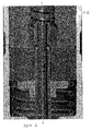
- Figure 1
- shows an exemplary embodiment of a valve assembly in a longitudinal section view and
- Figure 2
- shows an enlarged view of the section of the exem-plary embodiment of the valve assembly of
Figure 1 . -
Figure 1 shows avalve assembly 1 for an injection valve. The injection valve is a fluid injection valve, in particular a fuel injection valve for dosing fuel into the combustion chamber of an internal combustion engine. - The
valve assembly 1 comprises avalve body 2 with a central longitudinal axis L. Thevalve body 2 comprises acavity 3 with afluid inlet portion 18 in which apole piece 4 is located and a fluid outlet portion 19 where avalve seat 6 is arranged. - A
hollow valve needle 7 is arranged in thecavity 3 such that it is axially movable between a closed position and a fully open position. Thevalve needle 7 has a hollow shaft and a valve ball 5 fixed to one end of the shaft. Thevalve needle 7 prevents fluid flow through the fluid outlet portion 19 in the closed position by means of the valve ball 5 contacting theseat 6 for sealing the fluid outlet portion. In the fully open position, the valve ball 5 is spaced apart from theseat 6 so that thevalve needle 7 releases fluid through the fluid outlet portion 19. InFigures 1 and2 thevalve needle 7 is pictured in the fully open position. - The
valve needle 7 is coupled to anarmature 8 such that a first gap 9 exists between the outer surface of thevalve needle 7 and thearmature 8. The width of the first gap is maintained by an external armature guide which is represented by that portion of thevalve body 2 which axially overlaps thearmature 8. - The end of the shaft of the
valve needle 7 which is located in thefluid inlet portion 18 of thecavity 3 is fixedly coupled to aretainer 10, e.g. by welding. Thevalve needle 7 is attached to afirst spring element 11 via theretainer 10. The spring element maintains thevalve needle 7 in the closed position when no other forces are acting upon it. Thearmature 8 moves thevalve needle 7 into an open position against the force of thefirst spring element 11 by means of mechanical interaction with theretainer 10. Thearmature 8 is moved by an electromagnetic force generated by acoil 12 of the actuator assembly. Asecond spring 13 is attached to thearmature 8 to bias thearmature 8 towards theretainer 10. In particular, thearmature 8 is pushed into contact with theretainer 10 by thesecond spring 13 when no magnetic or other force is applied. - A disc element 14 - which may also be denoted as a hydro disc - is fixedly attached to the outer surface of the hollow shaft of the
valve needle 7 in such a position that it can decrease the velocity of thearmature 8 and ultimately stop the armature when thevalve needle 7 stops in the closed position and thearmature 8 decouples from theretainer 10 due to its inertia and moves further towards the fluid outlet portion 19. - As shown in
Figures 1 and2 there is asecond gap 15 between the armature and thehydro disc 14 in the open position. Thissecond gap 15 extends radially outward from the first gap 9 and connects to thecavity 3 volume. - The
valve needle 7 includes a number offirst orifices 16 axially located between thehydro disc 12 and the fluid outlet of thevalve assembly 1 and a number ofsecond orifices 17 axially located between thehydro disc 14 and theretainer 10. - In the present example the
second orifices 17 are arranged partially underneath theretainer 10, i.e. thesecond orifices 17 are partially covered by theretainer 10. In this way, fluid flow out of thesecond orifices 17 may advantageously be deflected away from a radial direction and towards the fluid outlet portion 19. - The first gap 9 is annular in shape but may alternatively be comprised of one or more channels connecting the fluid flowing from the
second orifices 17 to fluid in thecavity 3 in the vicinity of thesecond spring element 13. The first gap 9 extends, in axial direction, from thesecond orifices 17 to thesecond gap 15. Thus, fluid may flow out of the hollow shaft of thevalve needle 7 through thesecond orifices 17 in the sidewall of the shaft, may flow further in axial direction through the first gap 9 along thearmature 8 and the shaft and subsequently in radial direction through thesecond gap 15 along a bottom surface of thearmature 8 and along thedisc element 14. - When the
valve needle 7 is displaced away from the closed position to a further position towards the fully open position where thearmature 8 abuts thepole piece 4, fluid flows through thefluid inlet portion 18 of thecavity 3 inside of thepole piece 4 into thehollow valve needle 7. The bulk of the fluid flows through thehollow needle 7, leaves thehollow valve needle 7 through thefirst orifices 16 into the portion of thecavity 3 which surrounds thevalve needle 3 and is released from thecavity 3 at the fluid outlet portion 19 when thevalve needle 7 is displaced axially away from the closed position, i.e. when the valve ball 5 is spaced apart from theseat 6. A small portion of the fluid exits thevalve needle 7 via thesecond orifices 17 and flows into the portion of thecavity 3 between the outer surface of thevalve needle 7 and the inner surface of thevalve body 2 through the first andsecond gaps 9, 15. The position of thesecond orifices 17 leads to the reduction in magnitude of pressure pulsations.
Claims (6)
- Valve assembly (1) for an injection valve, comprising- a valve body (2) including a central longitudinal axis (L), the valve body (2) comprising a cavity (3) with a fluid inlet portion (18) and a fluid outlet portion (19),- a valve needle (7) which is hollow and axially movable in the cavity (3), the valve needle (7) preventing a fluid flow through the fluid outlet portion (19) in a closed position and releasing fluid through the fluid outlet portion (19) in further positions, wherein the valve needle (7) is arranged such that fluid can flow from the fluid inlet portion (18) into the hollow valve needle (7) and- an actuator assembly being configured to actuate the valve needle (7), the actuator assembly comprising an armature (8) axially movable in the cavity (3), wherein- the valve needle (7) comprises at least one first orifice (16) located axially between the armature (8) and the fluid outlet portion (19),- the valve needle (7) comprises at least one second orifice (17) located in the axial range of the armature (8) and /or an axial range extending away from the armature (8) beginning from an axial end of the armature (8) facing towards the fluid inlet portion (18),- the first and second orifices (16, 17) are configured to allow fluid flow between the hollow valve needle (7) and the cavity (3) and- the valve needle (7) and armature (8) are arranged such that a first gap (9) exists between the valve needle (7) and the armature (8) wherein the first gap (9) is provided to allow fluid flow from the hollow valve needle (7) via the second orifice (17) into the first gap (9) and further into the cavity (3).
- Valve assembly (1) according to claim 1, wherein the valve needle (7) has a retainer (10) for limiting axial displacement of the armature (8) with respect to the valve needle (7) in a direction away from the closed position and a disc element (14) on the side of the armature (8) opposite of the retainer (10) and positioned in such fashion that it is operable to limit axial displacement of the armature (8) with respect to the valve needle (7) in axial direction away from the retainer (10) and in such fashion that the armature (8) has a predefined axial play with respect to the valve needle (7) between the retainer (10) and the disc element (14).
- Valve assembly (1) according to claim 1 or 2, wherein the first gap (9) is annular in cross-section or comprised of one or more channels.
- Valve assembly (1) according to claim 3, wherein the first gap (9) is approximately 0.05 mm wide.
- Valve assembly (1) according to one of the preceding claims, which further comprises an external armature guide which is movably coupled to the outer surface of the armature (8).
- Injection valve with a valve assembly (1) according to one of the preceding claims.
Priority Applications (4)
| Application Number | Priority Date | Filing Date | Title |
|---|---|---|---|
| EP13180382.7A EP2837813B1 (en) | 2013-08-14 | 2013-08-14 | Valve assembly for an injection valve and injection valve |
| US14/293,237 US9494117B2 (en) | 2013-08-14 | 2014-06-02 | Valve assembly for an injection valve and injection valve |
| KR20140104449A KR20150020109A (en) | 2013-08-14 | 2014-08-12 | Valve assembly for an injection valve and injection valve |
| CN201410399110.XA CN104373267B (en) | 2013-08-14 | 2014-08-14 | Valve module and injection valve for injection valve |
Applications Claiming Priority (1)
| Application Number | Priority Date | Filing Date | Title |
|---|---|---|---|
| EP13180382.7A EP2837813B1 (en) | 2013-08-14 | 2013-08-14 | Valve assembly for an injection valve and injection valve |
Publications (2)
| Publication Number | Publication Date |
|---|---|
| EP2837813A1 true EP2837813A1 (en) | 2015-02-18 |
| EP2837813B1 EP2837813B1 (en) | 2016-04-06 |
Family
ID=48979645
Family Applications (1)
| Application Number | Title | Priority Date | Filing Date |
|---|---|---|---|
| EP13180382.7A Not-in-force EP2837813B1 (en) | 2013-08-14 | 2013-08-14 | Valve assembly for an injection valve and injection valve |
Country Status (4)
| Country | Link |
|---|---|
| US (1) | US9494117B2 (en) |
| EP (1) | EP2837813B1 (en) |
| KR (1) | KR20150020109A (en) |
| CN (1) | CN104373267B (en) |
Families Citing this family (5)
| Publication number | Priority date | Publication date | Assignee | Title |
|---|---|---|---|---|
| JP2017089425A (en) * | 2015-11-05 | 2017-05-25 | 株式会社デンソー | Fuel injection device |
| JP6504023B2 (en) * | 2015-11-05 | 2019-04-24 | 株式会社デンソー | Fuel injection device |
| JP2017089515A (en) * | 2015-11-11 | 2017-05-25 | 株式会社デンソー | Fuel injection device |
| DE102015226181A1 (en) * | 2015-12-21 | 2017-06-22 | Robert Bosch Gmbh | Valve for metering a fluid |
| GB2566291A (en) * | 2017-09-07 | 2019-03-13 | Artemis Intelligent Power Ltd | Valve assembly |
Citations (5)
| Publication number | Priority date | Publication date | Assignee | Title |
|---|---|---|---|---|
| US5199648A (en) * | 1991-03-20 | 1993-04-06 | Zexel Corporation | Fuel injection valve |
| DE102004053762A1 (en) * | 2004-11-08 | 2006-05-11 | Robert Bosch Gmbh | Valve needle for fluid valve has discharge holes with hole diameter of micrometer-range and which are distributed in large quantity over partial covering area of needle sleeve such that the needle sleeve itself forms filter |
| DE102005061409A1 (en) * | 2005-12-22 | 2007-06-28 | Robert Bosch Gmbh | Electromagnetic fuel injection valve for vehicles is closed by ball whose top fits against curved section at tip of valve needle |
| EP2375051A1 (en) * | 2010-04-09 | 2011-10-12 | Continental Automotive GmbH | Valve assembly for an injection valve and injection valve |
| US20120067982A1 (en) * | 2010-09-22 | 2012-03-22 | Delphi Technologies, Inc. | Fuel injector |
Family Cites Families (9)
| Publication number | Priority date | Publication date | Assignee | Title |
|---|---|---|---|---|
| US6209806B1 (en) * | 1999-01-11 | 2001-04-03 | Siemens Automotive Corporation | Pulsed air assist fuel injector |
| JP4092526B2 (en) * | 2000-06-19 | 2008-05-28 | 株式会社デンソー | Fuel injection device |
| DE10065528A1 (en) * | 2000-12-28 | 2002-07-04 | Bosch Gmbh Robert | Fuel injector |
| DE10108945A1 (en) * | 2001-02-24 | 2002-09-05 | Bosch Gmbh Robert | Fuel injector |
| DE10122353B4 (en) * | 2001-05-09 | 2004-04-22 | Robert Bosch Gmbh | Fuel injector |
| DE10142302A1 (en) * | 2001-08-29 | 2003-03-20 | Bosch Gmbh Robert | Fuel injection valve, for the direct fuel injection at an IC motor, has a guide sleeve for the armature return spring, within an axial recess at the valve needle to give a force fit bond with the armature and a firm seating for the spring |
| DE102005019837A1 (en) * | 2005-04-28 | 2006-11-02 | Robert Bosch Gmbh | Fuel injection valve for e.g. fuel injection systems of internal combustion engines has inlet port and nozzle member, which are produced as deep-drawn components while being fixed to magnetic circuit element |
| JP2009103080A (en) * | 2007-10-24 | 2009-05-14 | Denso Corp | Fuel injection valve |
| EP2354528B1 (en) * | 2010-01-15 | 2012-08-29 | Continental Automotive GmbH | Valve assembly and injection valve |
-
2013
- 2013-08-14 EP EP13180382.7A patent/EP2837813B1/en not_active Not-in-force
-
2014
- 2014-06-02 US US14/293,237 patent/US9494117B2/en not_active Expired - Fee Related
- 2014-08-12 KR KR20140104449A patent/KR20150020109A/en not_active Ceased
- 2014-08-14 CN CN201410399110.XA patent/CN104373267B/en not_active Expired - Fee Related
Patent Citations (5)
| Publication number | Priority date | Publication date | Assignee | Title |
|---|---|---|---|---|
| US5199648A (en) * | 1991-03-20 | 1993-04-06 | Zexel Corporation | Fuel injection valve |
| DE102004053762A1 (en) * | 2004-11-08 | 2006-05-11 | Robert Bosch Gmbh | Valve needle for fluid valve has discharge holes with hole diameter of micrometer-range and which are distributed in large quantity over partial covering area of needle sleeve such that the needle sleeve itself forms filter |
| DE102005061409A1 (en) * | 2005-12-22 | 2007-06-28 | Robert Bosch Gmbh | Electromagnetic fuel injection valve for vehicles is closed by ball whose top fits against curved section at tip of valve needle |
| EP2375051A1 (en) * | 2010-04-09 | 2011-10-12 | Continental Automotive GmbH | Valve assembly for an injection valve and injection valve |
| US20120067982A1 (en) * | 2010-09-22 | 2012-03-22 | Delphi Technologies, Inc. | Fuel injector |
Also Published As
| Publication number | Publication date |
|---|---|
| EP2837813B1 (en) | 2016-04-06 |
| CN104373267B (en) | 2018-03-27 |
| US9494117B2 (en) | 2016-11-15 |
| US20150048185A1 (en) | 2015-02-19 |
| KR20150020109A (en) | 2015-02-25 |
| CN104373267A (en) | 2015-02-25 |
Similar Documents
| Publication | Publication Date | Title |
|---|---|---|
| EP2333297B1 (en) | Valve assembly for an injection valve and injection valve | |
| EP2788614B1 (en) | Valve assembly arrangement for an injection valve and injection valve | |
| US8931718B2 (en) | Valve assembly for an injection valve and injection valve | |
| US9435305B2 (en) | Valve assembly for an injection valve and injection valve | |
| US20150041568A1 (en) | Valve Assembly For An Injection Valve And Injection Valve | |
| US9359984B2 (en) | Valve assembly for an injection valve and injection valve | |
| US9494117B2 (en) | Valve assembly for an injection valve and injection valve | |
| CN104583576B (en) | Valve assemblies and injection valves for injection valves | |
| EP2597296B1 (en) | Valve assembly for an injection valve and injection valve | |
| US9995262B2 (en) | Fluid injection valve | |
| US10550809B2 (en) | Valve assembly for an injection valve and injection valve | |
| CN106460750B (en) | Injectors for injecting fluids | |
| JP5479573B2 (en) | Injection valve | |
| EP2375051A1 (en) | Valve assembly for an injection valve and injection valve | |
| EP3339627B1 (en) | Valve assembly and fluid injection valve | |
| CN106930881A (en) | Valve for measuring fluid | |
| CN106795843A (en) | Injectors for injecting fluids | |
| EP2067981B1 (en) | Valve assembly for an injection valve and injection valve | |
| US20190211786A1 (en) | Valve Assembly for an Injection Valve and Injection Valve | |
| EP2426350A1 (en) | Valve assembly for an injection valve and injection valve | |
| EP2703633A1 (en) | Valve assembly for an injection valve and injection valve | |
| WO2015039859A1 (en) | Valve assembly for an injection valve and injection valve | |
| EP2241743A1 (en) | Valve assembly for an injection valve and injection valve |
Legal Events
| Date | Code | Title | Description |
|---|---|---|---|
| 17P | Request for examination filed |
Effective date: 20130814 |
|
| AK | Designated contracting states |
Kind code of ref document: A1 Designated state(s): AL AT BE BG CH CY CZ DE DK EE ES FI FR GB GR HR HU IE IS IT LI LT LU LV MC MK MT NL NO PL PT RO RS SE SI SK SM TR |
|
| AX | Request for extension of the european patent |
Extension state: BA ME |
|
| PUAI | Public reference made under article 153(3) epc to a published international application that has entered the european phase |
Free format text: ORIGINAL CODE: 0009012 |
|
| R17P | Request for examination filed (corrected) |
Effective date: 20150818 |
|
| RBV | Designated contracting states (corrected) |
Designated state(s): AL AT BE BG CH CY CZ DE DK EE ES FI FR GB GR HR HU IE IS IT LI LT LU LV MC MK MT NL NO PL PT RO RS SE SI SK SM TR |
|
| GRAP | Despatch of communication of intention to grant a patent |
Free format text: ORIGINAL CODE: EPIDOSNIGR1 |
|
| RIC1 | Information provided on ipc code assigned before grant |
Ipc: F02M 61/10 20060101ALI20150929BHEP Ipc: F02M 51/06 20060101AFI20150929BHEP Ipc: F02M 61/18 20060101ALI20150929BHEP |
|
| INTG | Intention to grant announced |
Effective date: 20151016 |
|
| GRAS | Grant fee paid |
Free format text: ORIGINAL CODE: EPIDOSNIGR3 |
|
| GRAA | (expected) grant |
Free format text: ORIGINAL CODE: 0009210 |
|
| AK | Designated contracting states |
Kind code of ref document: B1 Designated state(s): AL AT BE BG CH CY CZ DE DK EE ES FI FR GB GR HR HU IE IS IT LI LT LU LV MC MK MT NL NO PL PT RO RS SE SI SK SM TR |
|
| REG | Reference to a national code |
Ref country code: GB Ref legal event code: FG4D |
|
| REG | Reference to a national code |
Ref country code: AT Ref legal event code: REF Ref document number: 788109 Country of ref document: AT Kind code of ref document: T Effective date: 20160415 Ref country code: CH Ref legal event code: EP |
|
| REG | Reference to a national code |
Ref country code: IE Ref legal event code: FG4D |
|
| REG | Reference to a national code |
Ref country code: DE Ref legal event code: R096 Ref document number: 602013006131 Country of ref document: DE |
|
| REG | Reference to a national code |
Ref country code: LT Ref legal event code: MG4D Ref country code: NL Ref legal event code: MP Effective date: 20160406 |
|
| REG | Reference to a national code |
Ref country code: AT Ref legal event code: MK05 Ref document number: 788109 Country of ref document: AT Kind code of ref document: T Effective date: 20160406 |
|
| REG | Reference to a national code |
Ref country code: FR Ref legal event code: PLFP Year of fee payment: 4 |
|
| PG25 | Lapsed in a contracting state [announced via postgrant information from national office to epo] |
Ref country code: NL Free format text: LAPSE BECAUSE OF FAILURE TO SUBMIT A TRANSLATION OF THE DESCRIPTION OR TO PAY THE FEE WITHIN THE PRESCRIBED TIME-LIMIT Effective date: 20160406 |
|
| PG25 | Lapsed in a contracting state [announced via postgrant information from national office to epo] |
Ref country code: NO Free format text: LAPSE BECAUSE OF FAILURE TO SUBMIT A TRANSLATION OF THE DESCRIPTION OR TO PAY THE FEE WITHIN THE PRESCRIBED TIME-LIMIT Effective date: 20160706 Ref country code: IS Free format text: LAPSE BECAUSE OF FAILURE TO SUBMIT A TRANSLATION OF THE DESCRIPTION OR TO PAY THE FEE WITHIN THE PRESCRIBED TIME-LIMIT Effective date: 20160806 Ref country code: FI Free format text: LAPSE BECAUSE OF FAILURE TO SUBMIT A TRANSLATION OF THE DESCRIPTION OR TO PAY THE FEE WITHIN THE PRESCRIBED TIME-LIMIT Effective date: 20160406 Ref country code: PL Free format text: LAPSE BECAUSE OF FAILURE TO SUBMIT A TRANSLATION OF THE DESCRIPTION OR TO PAY THE FEE WITHIN THE PRESCRIBED TIME-LIMIT Effective date: 20160406 Ref country code: LT Free format text: LAPSE BECAUSE OF FAILURE TO SUBMIT A TRANSLATION OF THE DESCRIPTION OR TO PAY THE FEE WITHIN THE PRESCRIBED TIME-LIMIT Effective date: 20160406 |
|
| PG25 | Lapsed in a contracting state [announced via postgrant information from national office to epo] |
Ref country code: GR Free format text: LAPSE BECAUSE OF FAILURE TO SUBMIT A TRANSLATION OF THE DESCRIPTION OR TO PAY THE FEE WITHIN THE PRESCRIBED TIME-LIMIT Effective date: 20160707 Ref country code: LV Free format text: LAPSE BECAUSE OF FAILURE TO SUBMIT A TRANSLATION OF THE DESCRIPTION OR TO PAY THE FEE WITHIN THE PRESCRIBED TIME-LIMIT Effective date: 20160406 Ref country code: RS Free format text: LAPSE BECAUSE OF FAILURE TO SUBMIT A TRANSLATION OF THE DESCRIPTION OR TO PAY THE FEE WITHIN THE PRESCRIBED TIME-LIMIT Effective date: 20160406 Ref country code: AT Free format text: LAPSE BECAUSE OF FAILURE TO SUBMIT A TRANSLATION OF THE DESCRIPTION OR TO PAY THE FEE WITHIN THE PRESCRIBED TIME-LIMIT Effective date: 20160406 Ref country code: SE Free format text: LAPSE BECAUSE OF FAILURE TO SUBMIT A TRANSLATION OF THE DESCRIPTION OR TO PAY THE FEE WITHIN THE PRESCRIBED TIME-LIMIT Effective date: 20160406 Ref country code: PT Free format text: LAPSE BECAUSE OF FAILURE TO SUBMIT A TRANSLATION OF THE DESCRIPTION OR TO PAY THE FEE WITHIN THE PRESCRIBED TIME-LIMIT Effective date: 20160808 Ref country code: ES Free format text: LAPSE BECAUSE OF FAILURE TO SUBMIT A TRANSLATION OF THE DESCRIPTION OR TO PAY THE FEE WITHIN THE PRESCRIBED TIME-LIMIT Effective date: 20160406 Ref country code: HR Free format text: LAPSE BECAUSE OF FAILURE TO SUBMIT A TRANSLATION OF THE DESCRIPTION OR TO PAY THE FEE WITHIN THE PRESCRIBED TIME-LIMIT Effective date: 20160406 |
|
| PG25 | Lapsed in a contracting state [announced via postgrant information from national office to epo] |
Ref country code: BE Free format text: LAPSE BECAUSE OF FAILURE TO SUBMIT A TRANSLATION OF THE DESCRIPTION OR TO PAY THE FEE WITHIN THE PRESCRIBED TIME-LIMIT Effective date: 20160406 |
|
| REG | Reference to a national code |
Ref country code: DE Ref legal event code: R097 Ref document number: 602013006131 Country of ref document: DE |
|
| PG25 | Lapsed in a contracting state [announced via postgrant information from national office to epo] |
Ref country code: RO Free format text: LAPSE BECAUSE OF FAILURE TO SUBMIT A TRANSLATION OF THE DESCRIPTION OR TO PAY THE FEE WITHIN THE PRESCRIBED TIME-LIMIT Effective date: 20160406 Ref country code: SK Free format text: LAPSE BECAUSE OF FAILURE TO SUBMIT A TRANSLATION OF THE DESCRIPTION OR TO PAY THE FEE WITHIN THE PRESCRIBED TIME-LIMIT Effective date: 20160406 Ref country code: DK Free format text: LAPSE BECAUSE OF FAILURE TO SUBMIT A TRANSLATION OF THE DESCRIPTION OR TO PAY THE FEE WITHIN THE PRESCRIBED TIME-LIMIT Effective date: 20160406 Ref country code: CZ Free format text: LAPSE BECAUSE OF FAILURE TO SUBMIT A TRANSLATION OF THE DESCRIPTION OR TO PAY THE FEE WITHIN THE PRESCRIBED TIME-LIMIT Effective date: 20160406 Ref country code: EE Free format text: LAPSE BECAUSE OF FAILURE TO SUBMIT A TRANSLATION OF THE DESCRIPTION OR TO PAY THE FEE WITHIN THE PRESCRIBED TIME-LIMIT Effective date: 20160406 |
|
| PLBE | No opposition filed within time limit |
Free format text: ORIGINAL CODE: 0009261 |
|
| STAA | Information on the status of an ep patent application or granted ep patent |
Free format text: STATUS: NO OPPOSITION FILED WITHIN TIME LIMIT |
|
| PG25 | Lapsed in a contracting state [announced via postgrant information from national office to epo] |
Ref country code: SM Free format text: LAPSE BECAUSE OF FAILURE TO SUBMIT A TRANSLATION OF THE DESCRIPTION OR TO PAY THE FEE WITHIN THE PRESCRIBED TIME-LIMIT Effective date: 20160406 |
|
| 26N | No opposition filed |
Effective date: 20170110 |
|
| PG25 | Lapsed in a contracting state [announced via postgrant information from national office to epo] |
Ref country code: MC Free format text: LAPSE BECAUSE OF FAILURE TO SUBMIT A TRANSLATION OF THE DESCRIPTION OR TO PAY THE FEE WITHIN THE PRESCRIBED TIME-LIMIT Effective date: 20160406 |
|
| REG | Reference to a national code |
Ref country code: CH Ref legal event code: PL |
|
| PG25 | Lapsed in a contracting state [announced via postgrant information from national office to epo] |
Ref country code: CH Free format text: LAPSE BECAUSE OF NON-PAYMENT OF DUE FEES Effective date: 20160831 Ref country code: LI Free format text: LAPSE BECAUSE OF NON-PAYMENT OF DUE FEES Effective date: 20160831 |
|
| PG25 | Lapsed in a contracting state [announced via postgrant information from national office to epo] |
Ref country code: SI Free format text: LAPSE BECAUSE OF FAILURE TO SUBMIT A TRANSLATION OF THE DESCRIPTION OR TO PAY THE FEE WITHIN THE PRESCRIBED TIME-LIMIT Effective date: 20160406 |
|
| REG | Reference to a national code |
Ref country code: IE Ref legal event code: MM4A |
|
| PG25 | Lapsed in a contracting state [announced via postgrant information from national office to epo] |
Ref country code: IE Free format text: LAPSE BECAUSE OF NON-PAYMENT OF DUE FEES Effective date: 20160814 |
|
| REG | Reference to a national code |
Ref country code: FR Ref legal event code: PLFP Year of fee payment: 5 |
|
| PG25 | Lapsed in a contracting state [announced via postgrant information from national office to epo] |
Ref country code: LU Free format text: LAPSE BECAUSE OF NON-PAYMENT OF DUE FEES Effective date: 20160814 |
|
| PG25 | Lapsed in a contracting state [announced via postgrant information from national office to epo] |
Ref country code: HU Free format text: LAPSE BECAUSE OF FAILURE TO SUBMIT A TRANSLATION OF THE DESCRIPTION OR TO PAY THE FEE WITHIN THE PRESCRIBED TIME-LIMIT; INVALID AB INITIO Effective date: 20130814 |
|
| PG25 | Lapsed in a contracting state [announced via postgrant information from national office to epo] |
Ref country code: MK Free format text: LAPSE BECAUSE OF FAILURE TO SUBMIT A TRANSLATION OF THE DESCRIPTION OR TO PAY THE FEE WITHIN THE PRESCRIBED TIME-LIMIT Effective date: 20160406 Ref country code: CY Free format text: LAPSE BECAUSE OF FAILURE TO SUBMIT A TRANSLATION OF THE DESCRIPTION OR TO PAY THE FEE WITHIN THE PRESCRIBED TIME-LIMIT Effective date: 20160406 Ref country code: MT Free format text: LAPSE BECAUSE OF NON-PAYMENT OF DUE FEES Effective date: 20160831 |
|
| PG25 | Lapsed in a contracting state [announced via postgrant information from national office to epo] |
Ref country code: BG Free format text: LAPSE BECAUSE OF FAILURE TO SUBMIT A TRANSLATION OF THE DESCRIPTION OR TO PAY THE FEE WITHIN THE PRESCRIBED TIME-LIMIT Effective date: 20160406 |
|
| REG | Reference to a national code |
Ref country code: FR Ref legal event code: PLFP Year of fee payment: 6 |
|
| PG25 | Lapsed in a contracting state [announced via postgrant information from national office to epo] |
Ref country code: TR Free format text: LAPSE BECAUSE OF FAILURE TO SUBMIT A TRANSLATION OF THE DESCRIPTION OR TO PAY THE FEE WITHIN THE PRESCRIBED TIME-LIMIT Effective date: 20160406 Ref country code: AL Free format text: LAPSE BECAUSE OF FAILURE TO SUBMIT A TRANSLATION OF THE DESCRIPTION OR TO PAY THE FEE WITHIN THE PRESCRIBED TIME-LIMIT Effective date: 20160406 |
|
| PGFP | Annual fee paid to national office [announced via postgrant information from national office to epo] |
Ref country code: FR Payment date: 20180827 Year of fee payment: 6 Ref country code: IT Payment date: 20180830 Year of fee payment: 6 Ref country code: DE Payment date: 20180831 Year of fee payment: 6 |
|
| PGFP | Annual fee paid to national office [announced via postgrant information from national office to epo] |
Ref country code: GB Payment date: 20180822 Year of fee payment: 6 |
|
| REG | Reference to a national code |
Ref country code: DE Ref legal event code: R119 Ref document number: 602013006131 Country of ref document: DE |
|
| GBPC | Gb: european patent ceased through non-payment of renewal fee |
Effective date: 20190814 |
|
| PG25 | Lapsed in a contracting state [announced via postgrant information from national office to epo] |
Ref country code: DE Free format text: LAPSE BECAUSE OF NON-PAYMENT OF DUE FEES Effective date: 20200303 Ref country code: FR Free format text: LAPSE BECAUSE OF NON-PAYMENT OF DUE FEES Effective date: 20190831 |
|
| PG25 | Lapsed in a contracting state [announced via postgrant information from national office to epo] |
Ref country code: GB Free format text: LAPSE BECAUSE OF NON-PAYMENT OF DUE FEES Effective date: 20190814 Ref country code: IT Free format text: LAPSE BECAUSE OF NON-PAYMENT OF DUE FEES Effective date: 20190814 |