EP2837803A1 - Dual-fuel diesel engine and method for operating same - Google Patents
Dual-fuel diesel engine and method for operating same Download PDFInfo
- Publication number
- EP2837803A1 EP2837803A1 EP13776253.0A EP13776253A EP2837803A1 EP 2837803 A1 EP2837803 A1 EP 2837803A1 EP 13776253 A EP13776253 A EP 13776253A EP 2837803 A1 EP2837803 A1 EP 2837803A1
- Authority
- EP
- European Patent Office
- Prior art keywords
- gas
- fuel
- gas fuel
- replacement
- dual
- Prior art date
- Legal status (The legal status is an assumption and is not a legal conclusion. Google has not performed a legal analysis and makes no representation as to the accuracy of the status listed.)
- Withdrawn
Links
- 239000000446 fuel Substances 0.000 title claims abstract description 203
- 238000000034 method Methods 0.000 title claims description 10
- 238000002485 combustion reaction Methods 0.000 claims abstract description 81
- 238000002347 injection Methods 0.000 claims description 16
- 239000007924 injection Substances 0.000 claims description 16
- 238000001514 detection method Methods 0.000 claims description 3
- 230000009977 dual effect Effects 0.000 abstract description 5
- 239000007789 gas Substances 0.000 description 150
- VNWKTOKETHGBQD-UHFFFAOYSA-N methane Chemical compound C VNWKTOKETHGBQD-UHFFFAOYSA-N 0.000 description 6
- 230000002000 scavenging effect Effects 0.000 description 5
- 239000011261 inert gas Substances 0.000 description 3
- 239000003345 natural gas Substances 0.000 description 3
- IJGRMHOSHXDMSA-UHFFFAOYSA-N Atomic nitrogen Chemical compound N#N IJGRMHOSHXDMSA-UHFFFAOYSA-N 0.000 description 2
- 229910001873 dinitrogen Inorganic materials 0.000 description 2
- 239000007788 liquid Substances 0.000 description 2
- 230000000903 blocking effect Effects 0.000 description 1
- 230000003247 decreasing effect Effects 0.000 description 1
- 238000010586 diagram Methods 0.000 description 1
- 230000000694 effects Effects 0.000 description 1
- 239000000463 material Substances 0.000 description 1
- 239000000243 solution Substances 0.000 description 1
- 238000011144 upstream manufacturing Methods 0.000 description 1
Images

Classifications
-
- F—MECHANICAL ENGINEERING; LIGHTING; HEATING; WEAPONS; BLASTING
- F02—COMBUSTION ENGINES; HOT-GAS OR COMBUSTION-PRODUCT ENGINE PLANTS
- F02B—INTERNAL-COMBUSTION PISTON ENGINES; COMBUSTION ENGINES IN GENERAL
- F02B25/00—Engines characterised by using fresh charge for scavenging cylinders
- F02B25/02—Engines characterised by using fresh charge for scavenging cylinders using unidirectional scavenging
- F02B25/04—Engines having ports both in cylinder head and in cylinder wall near bottom of piston stroke
-
- F—MECHANICAL ENGINEERING; LIGHTING; HEATING; WEAPONS; BLASTING
- F02—COMBUSTION ENGINES; HOT-GAS OR COMBUSTION-PRODUCT ENGINE PLANTS
- F02M—SUPPLYING COMBUSTION ENGINES IN GENERAL WITH COMBUSTIBLE MIXTURES OR CONSTITUENTS THEREOF
- F02M43/00—Fuel-injection apparatus operating simultaneously on two or more fuels, or on a liquid fuel and another liquid, e.g. the other liquid being an anti-knock additive
- F02M43/04—Injectors peculiar thereto
-
- F—MECHANICAL ENGINEERING; LIGHTING; HEATING; WEAPONS; BLASTING
- F02—COMBUSTION ENGINES; HOT-GAS OR COMBUSTION-PRODUCT ENGINE PLANTS
- F02D—CONTROLLING COMBUSTION ENGINES
- F02D19/00—Controlling engines characterised by their use of non-liquid fuels, pluralities of fuels, or non-fuel substances added to the combustible mixtures
- F02D19/06—Controlling engines characterised by their use of non-liquid fuels, pluralities of fuels, or non-fuel substances added to the combustible mixtures peculiar to engines working with pluralities of fuels, e.g. alternatively with light and heavy fuel oil, other than engines indifferent to the fuel consumed
- F02D19/0602—Control of components of the fuel supply system
- F02D19/0607—Control of components of the fuel supply system to adjust the fuel mass or volume flow
- F02D19/061—Control of components of the fuel supply system to adjust the fuel mass or volume flow by controlling fuel injectors
-
- F—MECHANICAL ENGINEERING; LIGHTING; HEATING; WEAPONS; BLASTING
- F02—COMBUSTION ENGINES; HOT-GAS OR COMBUSTION-PRODUCT ENGINE PLANTS
- F02D—CONTROLLING COMBUSTION ENGINES
- F02D19/00—Controlling engines characterised by their use of non-liquid fuels, pluralities of fuels, or non-fuel substances added to the combustible mixtures
- F02D19/06—Controlling engines characterised by their use of non-liquid fuels, pluralities of fuels, or non-fuel substances added to the combustible mixtures peculiar to engines working with pluralities of fuels, e.g. alternatively with light and heavy fuel oil, other than engines indifferent to the fuel consumed
- F02D19/0663—Details on the fuel supply system, e.g. tanks, valves, pipes, pumps, rails, injectors or mixers
- F02D19/0686—Injectors
- F02D19/0689—Injectors for in-cylinder direct injection
-
- F—MECHANICAL ENGINEERING; LIGHTING; HEATING; WEAPONS; BLASTING
- F02—COMBUSTION ENGINES; HOT-GAS OR COMBUSTION-PRODUCT ENGINE PLANTS
- F02D—CONTROLLING COMBUSTION ENGINES
- F02D19/00—Controlling engines characterised by their use of non-liquid fuels, pluralities of fuels, or non-fuel substances added to the combustible mixtures
- F02D19/06—Controlling engines characterised by their use of non-liquid fuels, pluralities of fuels, or non-fuel substances added to the combustible mixtures peculiar to engines working with pluralities of fuels, e.g. alternatively with light and heavy fuel oil, other than engines indifferent to the fuel consumed
- F02D19/0663—Details on the fuel supply system, e.g. tanks, valves, pipes, pumps, rails, injectors or mixers
- F02D19/0686—Injectors
- F02D19/0692—Arrangement of multiple injectors per combustion chamber
-
- F—MECHANICAL ENGINEERING; LIGHTING; HEATING; WEAPONS; BLASTING
- F02—COMBUSTION ENGINES; HOT-GAS OR COMBUSTION-PRODUCT ENGINE PLANTS
- F02D—CONTROLLING COMBUSTION ENGINES
- F02D19/00—Controlling engines characterised by their use of non-liquid fuels, pluralities of fuels, or non-fuel substances added to the combustible mixtures
- F02D19/06—Controlling engines characterised by their use of non-liquid fuels, pluralities of fuels, or non-fuel substances added to the combustible mixtures peculiar to engines working with pluralities of fuels, e.g. alternatively with light and heavy fuel oil, other than engines indifferent to the fuel consumed
- F02D19/08—Controlling engines characterised by their use of non-liquid fuels, pluralities of fuels, or non-fuel substances added to the combustible mixtures peculiar to engines working with pluralities of fuels, e.g. alternatively with light and heavy fuel oil, other than engines indifferent to the fuel consumed simultaneously using pluralities of fuels
- F02D19/10—Controlling engines characterised by their use of non-liquid fuels, pluralities of fuels, or non-fuel substances added to the combustible mixtures peculiar to engines working with pluralities of fuels, e.g. alternatively with light and heavy fuel oil, other than engines indifferent to the fuel consumed simultaneously using pluralities of fuels peculiar to compression-ignition engines in which the main fuel is gaseous
- F02D19/105—Controlling engines characterised by their use of non-liquid fuels, pluralities of fuels, or non-fuel substances added to the combustible mixtures peculiar to engines working with pluralities of fuels, e.g. alternatively with light and heavy fuel oil, other than engines indifferent to the fuel consumed simultaneously using pluralities of fuels peculiar to compression-ignition engines in which the main fuel is gaseous operating in a special mode, e.g. in a liquid fuel only mode for starting
-
- F—MECHANICAL ENGINEERING; LIGHTING; HEATING; WEAPONS; BLASTING
- F02—COMBUSTION ENGINES; HOT-GAS OR COMBUSTION-PRODUCT ENGINE PLANTS
- F02D—CONTROLLING COMBUSTION ENGINES
- F02D19/00—Controlling engines characterised by their use of non-liquid fuels, pluralities of fuels, or non-fuel substances added to the combustible mixtures
- F02D19/12—Controlling engines characterised by their use of non-liquid fuels, pluralities of fuels, or non-fuel substances added to the combustible mixtures peculiar to engines working with non-fuel substances or with anti-knock agents, e.g. with anti-knock fuel
-
- F—MECHANICAL ENGINEERING; LIGHTING; HEATING; WEAPONS; BLASTING
- F02—COMBUSTION ENGINES; HOT-GAS OR COMBUSTION-PRODUCT ENGINE PLANTS
- F02D—CONTROLLING COMBUSTION ENGINES
- F02D35/00—Controlling engines, dependent on conditions exterior or interior to engines, not otherwise provided for
- F02D35/02—Controlling engines, dependent on conditions exterior or interior to engines, not otherwise provided for on interior conditions
- F02D35/023—Controlling engines, dependent on conditions exterior or interior to engines, not otherwise provided for on interior conditions by determining the cylinder pressure
-
- F—MECHANICAL ENGINEERING; LIGHTING; HEATING; WEAPONS; BLASTING
- F02—COMBUSTION ENGINES; HOT-GAS OR COMBUSTION-PRODUCT ENGINE PLANTS
- F02D—CONTROLLING COMBUSTION ENGINES
- F02D41/00—Electrical control of supply of combustible mixture or its constituents
- F02D41/0025—Controlling engines characterised by use of non-liquid fuels, pluralities of fuels, or non-fuel substances added to the combustible mixtures
-
- F—MECHANICAL ENGINEERING; LIGHTING; HEATING; WEAPONS; BLASTING
- F02—COMBUSTION ENGINES; HOT-GAS OR COMBUSTION-PRODUCT ENGINE PLANTS
- F02D—CONTROLLING COMBUSTION ENGINES
- F02D41/00—Electrical control of supply of combustible mixture or its constituents
- F02D41/30—Controlling fuel injection
- F02D41/3011—Controlling fuel injection according to or using specific or several modes of combustion
- F02D41/3064—Controlling fuel injection according to or using specific or several modes of combustion with special control during transition between modes
-
- F—MECHANICAL ENGINEERING; LIGHTING; HEATING; WEAPONS; BLASTING
- F02—COMBUSTION ENGINES; HOT-GAS OR COMBUSTION-PRODUCT ENGINE PLANTS
- F02D—CONTROLLING COMBUSTION ENGINES
- F02D41/00—Electrical control of supply of combustible mixture or its constituents
- F02D41/30—Controlling fuel injection
- F02D41/3094—Controlling fuel injection the fuel injection being effected by at least two different injectors, e.g. one in the intake manifold and one in the cylinder
-
- F—MECHANICAL ENGINEERING; LIGHTING; HEATING; WEAPONS; BLASTING
- F02—COMBUSTION ENGINES; HOT-GAS OR COMBUSTION-PRODUCT ENGINE PLANTS
- F02D—CONTROLLING COMBUSTION ENGINES
- F02D41/00—Electrical control of supply of combustible mixture or its constituents
- F02D41/30—Controlling fuel injection
- F02D41/38—Controlling fuel injection of the high pressure type
- F02D2041/389—Controlling fuel injection of the high pressure type for injecting directly into the cylinder
-
- F—MECHANICAL ENGINEERING; LIGHTING; HEATING; WEAPONS; BLASTING
- F02—COMBUSTION ENGINES; HOT-GAS OR COMBUSTION-PRODUCT ENGINE PLANTS
- F02D—CONTROLLING COMBUSTION ENGINES
- F02D41/00—Electrical control of supply of combustible mixture or its constituents
- F02D41/0025—Controlling engines characterised by use of non-liquid fuels, pluralities of fuels, or non-fuel substances added to the combustible mixtures
- F02D41/0027—Controlling engines characterised by use of non-liquid fuels, pluralities of fuels, or non-fuel substances added to the combustible mixtures the fuel being gaseous
-
- F—MECHANICAL ENGINEERING; LIGHTING; HEATING; WEAPONS; BLASTING
- F02—COMBUSTION ENGINES; HOT-GAS OR COMBUSTION-PRODUCT ENGINE PLANTS
- F02D—CONTROLLING COMBUSTION ENGINES
- F02D41/00—Electrical control of supply of combustible mixture or its constituents
- F02D41/009—Electrical control of supply of combustible mixture or its constituents using means for generating position or synchronisation signals
-
- F—MECHANICAL ENGINEERING; LIGHTING; HEATING; WEAPONS; BLASTING
- F02—COMBUSTION ENGINES; HOT-GAS OR COMBUSTION-PRODUCT ENGINE PLANTS
- F02D—CONTROLLING COMBUSTION ENGINES
- F02D41/00—Electrical control of supply of combustible mixture or its constituents
- F02D41/30—Controlling fuel injection
- F02D41/3011—Controlling fuel injection according to or using specific or several modes of combustion
- F02D41/3017—Controlling fuel injection according to or using specific or several modes of combustion characterised by the mode(s) being used
- F02D41/3035—Controlling fuel injection according to or using specific or several modes of combustion characterised by the mode(s) being used a mode being the premixed charge compression-ignition mode
- F02D41/3041—Controlling fuel injection according to or using specific or several modes of combustion characterised by the mode(s) being used a mode being the premixed charge compression-ignition mode with means for triggering compression ignition, e.g. spark plug
- F02D41/3047—Controlling fuel injection according to or using specific or several modes of combustion characterised by the mode(s) being used a mode being the premixed charge compression-ignition mode with means for triggering compression ignition, e.g. spark plug said means being a secondary injection of fuel
-
- Y—GENERAL TAGGING OF NEW TECHNOLOGICAL DEVELOPMENTS; GENERAL TAGGING OF CROSS-SECTIONAL TECHNOLOGIES SPANNING OVER SEVERAL SECTIONS OF THE IPC; TECHNICAL SUBJECTS COVERED BY FORMER USPC CROSS-REFERENCE ART COLLECTIONS [XRACs] AND DIGESTS
- Y02—TECHNOLOGIES OR APPLICATIONS FOR MITIGATION OR ADAPTATION AGAINST CLIMATE CHANGE
- Y02T—CLIMATE CHANGE MITIGATION TECHNOLOGIES RELATED TO TRANSPORTATION
- Y02T10/00—Road transport of goods or passengers
- Y02T10/10—Internal combustion engine [ICE] based vehicles
- Y02T10/30—Use of alternative fuels, e.g. biofuels
Definitions
- the present invention relates to a dual-fuel diesel engine and an operation method of the same, in which, using an oil fuel such as gas oil having high compression-ignition properties as a pilot fuel, the oil fuel and a gas fuel are injected so as to cause self-ignition of the oil fuel, thereby combusting the gas fuel.
- an oil fuel such as gas oil having high compression-ignition properties as a pilot fuel
- the oil fuel and a gas fuel are injected so as to cause self-ignition of the oil fuel, thereby combusting the gas fuel.
- a dual-fuel diesel engine where a gas fuel such as natural gas or the like is used as a main fuel while an oil fuel having high compression-ignition properties is used as a pilot fuel, and the oil fuel is caused to self-ignite inside a high-temperature combustion chamber so as to combust the gas fuel being the main fuel.
- An object of a dual-fuel diesel engine is, by using a gas fuel that can be easily mixed with the air, to prevent incomplete combustion and to make exhaust gas less harmful, as well as to reduce fuel cost.
- Patent Documents 1 and 2 disclose a dual-fuel diesel engine.
- the dual-fuel diesel engine in Patent Document 1 is configured such that a pilot fuel injection valve is positioned upstream in the direction of a swirl flow with respect to a gas fuel injection valve, and a pilot fuel and a gas fuel are injected in the flowing direction of the swirl, so as to securely ignite the gas fuel.
- Patent Document 2 proposes a dual-fuel diesel engine that makes it possible to modify an existing diesel engine to a dual-fuel diesel engine at low cost.
- Patent Document 1 JPS62-45339 (Utility model application); specification and drawings
- a dual-fuel diesel engine has a dual-combustion mode in which an oil fuel and a gas fuel are injected at the same time, and a single-combustion mode in which only the oil fuel is solely injected.
- the single-combustion mode is, for instance, operated in an extremely-low operating range immediately after starting operation.
- combustion residues adhering to a nozzle hole of a gas fuel injector and blocking the nozzle hole during the single-combustion mode As a result, there is a problem raised in the smooth shift to the dual-combustion mode.
- an object of the present invention is to, in a dual-fuel diesel engine, prevent blockage of the nozzle hole of a gas fuel injector during operation in the single-combustion mode so as to smoothly shift from the single-combustion mode to the dual-combustion mode.
- an operation method for a dual-fuel diesel engine of the present invention includes: a first step of operating the dual-fuel diesel engine in a single injection mode in which only oil fuel is injected into the combustion chamber; and a second step of injecting a replacement gas from the gas fuel injector so as to remove a combustion residues adhering to a nozzle hole of the gas fuel injector upon a pressure in the combustion chamber becoming lower than a supply pressure of the replacement gas during operation in the single combustion mode.
- a supply unit of the replacement gas includes a replacement gas reservoir tank connected to the gas fuel injector through a replacement gas supply path
- the replacement gas may be injected into the combustion chamber from the replacement gas reservoir tank upon the pressure in the combustion chamber becoming lower than a pressure in the replacement gas reservoir tank.
- a dual-fuel diesel engine of the present invention that can be directly used to implement the method of the present invention includes: an oil fuel supply device configured to supply the oil fuel to a pilot fuel injector; a gas fuel supply device configured to supply the gas fuel to a gas fuel injector; a replacement gas supply device configured to supply a replacement gas to the gas fuel injector; a piston position detection device configured to detect a position of the piston; and a controller configured to inject the replacement gas from the gas fuel injector upon a pressure in the combustion chamber becoming lower than a supply pressure of the replacement gas during operation in a single injection mode in which only the oil fuel is injected into the combustion chamber.
- the gas fuel supply device includes a gas fuel reservoir tank connected to the gas fuel injector via a gas fuel supply path and a first opening-and-closing valve disposed in the gas fuel supply path.
- the replacement gas supply device may include a replacement gas reservoir tank connected to the gas fuel injector via a replacement gas fuel supply path that branches from the gas fuel supply path at a downstream side relative to the first opening-and-closing valve and a second opening-and-closing valve disposed in the replacement gas supply path.
- the dual-fuel diesel engine may further include an atmosphere introducing path that branches from the gas fuel supply path at a downstream side relative to a branch point where the replacement gas supply path branches and a third opening-and-closing valve disposed in the atmosphere introducing path.
- the controller may be configured capable of controlling each of the opening-and-closing valves.
- the present invention during operation in the single injection mode in which only the oil fuel is injected, it is possible to blow off combustion residues adhering to the nozzle holes of the gas fuel injectors by injecting the replacement gas from the gas fuel injectors.
- the piston upon the piston being in the region of the bottom dead center and the combustion chamber having low pressure, it becomes easier to inject the replacement gas by injecting the replacement gas from the gas fuel injectors.
- FIGs. 1 to 4 An embodiment of a dual-fuel diesel engine to which the present invention is applied will be described in reference to FIGs. 1 to 4 .
- the present embodiment is an example where the present invention is applied to a two-cycle dual-fuel diesel engine.
- a dual-fuel diesel engine 10 of the present embodiment includes a cylinder 12 of a cylindrical shape, a cylinder head 14 connected to the upper end of the cylinder 12, and a piston 16 housed inside the cylinder 12 so as to be freely reciprocable.
- a combustion chamber “c" is defined by the surrounding wall 12a of the cylinder 12, the cylinder head 14, and the top face 16a of the piston 16.
- piston rings 18 are disposed on the outer circumferential face of the piston 16 so as to seal a gap between the outer circumferential face of the piston 16 and the surrounding wall 12a of the cylinder 12.
- a plurality of scavenging ports 20 are opened at equal intervals in the circumferential direction.
- the scavenging ports 20 are formed above the top face 16a of the piston 16 being positioned in the region of the bottom dead center (as indicated by the double-dotted chain line in the drawing).
- air is supplied to the combustion chamber "c" from the scavenging ports 20.
- an exhaust valve 22 is disposed on the exhaust port for opening and closing the exhaust port.
- this exhaust valve 22 is kept open until the piston 16 reaches the position of approximately 100° before top dead center. Then, the air supplied to the combustion chamber "c" from the scavenging ports 20 scavenges the exhaust gas from the previous stroke that has remained in the combustion chamber "c".
- a pair of dual-fuel injectors 24a, 24b is disposed around the exhaust valve 22.
- the dual-fuel injectors 24a, 24b are arranged so that they are symmetric about the central axis line of the cylinder 12 at an interval of 180° from each other.
- the dual-fuel injection devices 24a, 24b each include a gas fuel injector 26 that injects a gas fuel "g” such as natural gas to the combustion chamber "c" and a pilot fuel injector 28 that similarly injects an oil fuel "o" having high compression-ignition properties to the combustion chamber "c".
- the gas fuel injectors 26 and the pilot fuel injectors 28 are connected to an engine control unit (ECU) 30 through cables 32, so that the ECU 12 controls fuel injecting operation.
- the ECU 30 is connected to a crank angle sensor 36 that detects a rotation angle of a crank shaft 34 through a cable 38.
- the ECU 30 detects a phase of the piston 16 by receiving a detection signal of a rotation angle of the crank shaft 34 from the crank angle sensor 36 through the cable 38.
- the gas fuel injectors 26 and the pilot fuel injectors 28 inject a gas fuel "g” and an oil fuel “o” into the combustion chamber "c" at a predetermined timing based on a signal transmitted from the ECU 30.
- the gas fuel injectors 26 and the pilot fuel injectors 28 inject the corresponding fuels nearly at the same time.
- the oil fuel "o” having high compression-ignition properties self-ignites, which causes the gas fuel "g” injected nearly at the same time to combust so as to generate flame in the combustion chamber "c".
- an oil fuel reservoir tank 40 In the vicinity of the dual-fuel diesel engine 10, an oil fuel reservoir tank 40, a gas fuel reservoir tank 42 and a replacement gas reservoir tank 44 are disposed.
- the oil fuel reservoir tank 40 is connected to the oil fuel injectors 28 of the dual-fuel injectors 24a, 24b through oil fuel supply path 46.
- a liquid pump 48 is disposed in the oil fuel supply path 46.
- the gas fuel reservoir tank 42 is connected to the gas fuel injectors 26 of the dual-fuel injectors 24a, 24b through the gas fuel supply path 50.
- An oil fuel is stored in the oil fuel reservoir tank 40, while a gas fuel such as natural gas is stored in a pressurized state in the gas fuel reservoir tank 42.
- An electromagnetic opening-and-closing valve V 1 is disposed in the gas fuel supply path 50.
- the gas fuel supply path 50 is connected to the replacement gas reservoir tank 44 through a replacement gas supply path 52.
- the replacement gas supply path 52 is connected to the gas fuel supply path 50 at the downstream side relative to the electromagnetic opening-and-closing valve V 1 .
- an inert gas such as nitrogen gas or air is stored in a pressurized state as a replacement gas.
- an atmosphere introducing path 54 is connected at the downstream side relative to the connection point to the replacement gas supply path 52.
- An electromagnetic opening-and-closing valve V 3 is disposed in the atmosphere introducing path 54.
- the liquid pump 48 and the electromagnetic opening-and-closing valves V 1 to V 3 are connected to the ECU 30 through cables 56, so that the ECU 30 controls their operations.
- the dual-fuel injectors 24a, 24b normally inject both of the gas fuel "g" and the oil fuel “o" (dual-fuel combustion mode).
- injection of the gas fuel from the gas fuel injectors 26 is stopped and only the oil fuel "o” is injected from the oil fuel injectors 28 (single combustion mode).
- the line A represents the pressure of the combustion chamber "c”
- the line B represents the pressure of the replacement gas inside the replacement gas reservoir tank 44
- the line C represents the time when the replacement gas is injected from the gas fuel injectors 26.
- the replacement gas pressure inside the replacement gas reservoir tank 44 is kept constant.
- the time “d” when the replacement gas is injected from the gas fuel injectors 26 is selected to be in the time range R in which the piston 16 is positioned in the region of the bottom dead center and the pressure of the combustion chamber "c" is lower than the pressure inside the replacement gas reservoir tank 44.
- the ECU 30 when shifting from the dual-fuel combustion mode to the single combustion mode, the ECU 30 performs opening-and-closing operations for the electromagnetic opening-and-closing valves V 1 , V 2 and V 3 according to the procedure illustrated in FIG. 4 .
- the ECU 30 controls the electromagnetic opening-and-closing valve V 1 to be open and the electromagnetic opening-and-closing valves V 2 and V 3 to be closed.
- the electromagnetic opening-and-closing valve V 1 is closed so as to block the gas fuel.
- the electromagnetic opening-and-closing valve V 3 is opened to discharge the gas fuel remaining in the gas fuel supply path 50 to the outside of the system.
- the electromagnetic opening-and-closing valve V 2 is opened to introduce the replacement gas from the replacement gas reservoir tank 44 into the gas fuel supply path 50 so as to replace contents in the gas fuel supply path 50 with the replacement gas.
- the electromagnetic opening-and-closing valves V 2 and V 3 are closed.
- the electromagnetic opening-and-closing valve V 2 is opened to inject the replacement gas from the gas fuel injectors 26.
- the electromagnetic opening-and-closing valve V 2 is closed at first, and then the electromagnetic opening-and-closing valve V 3 is opened so as to discharge the replacement gas inside the gas fuel supply path 50 to the outside of the system. Then, the electromagnetic opening-and-closing valve V 1 is opened to replace the contents of the gas fuel supply path 50 with the gas fuel. Further, the electromagnetic opening-and-closing valve V 3 is closed to supply the gas fuel "g" to the gas fuel injectors 26.
- the replacement gas by injecting the replacement gas from the gas fuel injectors 26 during operation in the single injection mode in which the oil fuel "o" is injected, it is possible to blow off the combustion residues adhering to the nozzle holes of the gas fuel injectors 26. As a result, it is possible to prevent blockage of the nozzle holes of the gas fuel injectors 26 and to shift from the single combustion mode to the dual combustion mode smoothly. Further, by injecting the replacement gas in the time range R in which the piston 16 is positioned in the region of the bottom dead center and the pressure of the combustion chamber "c" is lower than the pressure inside the replacement gas reservoir tank 44, injection of the replacement gas is facilitated.
- the replacement gas inside the inert gas reservoir tank 44 is injected from the gas fuel injectors 26 by its own pressure.
- the ECU 30 only controls the electromagnetic opening-and-closing valves V 1 , V 2 and V 3 .
- the ECU 30 upon switching between the dual combustion mode and the single combustion mode, it is possible to discharge the gas fuel or the replacement gas remaining in the gas fuel supply path 50 to the outside air from the atmosphere introducing path 54. As a result, the previously remaining gas is not injected from the gas fuel injectors 26 immediately after the switch, which makes it possible to smoothly switch to supplying the next gas.
- the present invention is an example where a pair of dual-fuel injectors 24a, 24b is disposed on the cylinder head 14, the present invention may be applied to the case where there is one dual-fuel injector, or there are three or more of the same. Further, while the present embodiment is an example where the present invention is applied to a two-cycle dual-fuel diesel engine, the present invention may be applied to a four-cycle dual-fuel diesel engine.
- the present invention during operation in the single combustion mode where only an oil fuel is injected, it is possible to prevent blockage of the nozzle holes of the gas fuel injectors and to smoothly shift from the single combustion mode to the dual combustion mode.
Landscapes
- Engineering & Computer Science (AREA)
- Chemical & Material Sciences (AREA)
- Combustion & Propulsion (AREA)
- Mechanical Engineering (AREA)
- General Engineering & Computer Science (AREA)
- Oil, Petroleum & Natural Gas (AREA)
- Output Control And Ontrol Of Special Type Engine (AREA)
- Fuel-Injection Apparatus (AREA)
- Combustion Methods Of Internal-Combustion Engines (AREA)
Abstract
Description
- The present invention relates to a dual-fuel diesel engine and an operation method of the same, in which, using an oil fuel such as gas oil having high compression-ignition properties as a pilot fuel, the oil fuel and a gas fuel are injected so as to cause self-ignition of the oil fuel, thereby combusting the gas fuel.
- Conventionally, there has been known a dual-fuel diesel engine where a gas fuel such as natural gas or the like is used as a main fuel while an oil fuel having high compression-ignition properties is used as a pilot fuel, and the oil fuel is caused to self-ignite inside a high-temperature combustion chamber so as to combust the gas fuel being the main fuel. An object of a dual-fuel diesel engine is, by using a gas fuel that can be easily mixed with the air, to prevent incomplete combustion and to make exhaust gas less harmful, as well as to reduce fuel cost.
-
Patent Documents 1 and 2 disclose a dual-fuel diesel engine. The dual-fuel diesel engine inPatent Document 1 is configured such that a pilot fuel injection valve is positioned upstream in the direction of a swirl flow with respect to a gas fuel injection valve, and a pilot fuel and a gas fuel are injected in the flowing direction of the swirl, so as to securely ignite the gas fuel. Patent Document 2 proposes a dual-fuel diesel engine that makes it possible to modify an existing diesel engine to a dual-fuel diesel engine at low cost. - Patent Document 1: JPS62-45339 (Utility model application); specification and drawings
- A dual-fuel diesel engine has a dual-combustion mode in which an oil fuel and a gas fuel are injected at the same time, and a single-combustion mode in which only the oil fuel is solely injected. The single-combustion mode is, for instance, operated in an extremely-low operating range immediately after starting operation. However, there is a possibility of combustion residues adhering to a nozzle hole of a gas fuel injector and blocking the nozzle hole during the single-combustion mode. As a result, there is a problem raised in the smooth shift to the dual-combustion mode.
- In view of the above problem of the prior art, an object of the present invention is to, in a dual-fuel diesel engine, prevent blockage of the nozzle hole of a gas fuel injector during operation in the single-combustion mode so as to smoothly shift from the single-combustion mode to the dual-combustion mode.
- In order to achieve the above object, an operation method for a dual-fuel diesel engine of the present invention includes: a first step of operating the dual-fuel diesel engine in a single injection mode in which only oil fuel is injected into the combustion chamber; and a second step of injecting a replacement gas from the gas fuel injector so as to remove a combustion residues adhering to a nozzle hole of the gas fuel injector upon a pressure in the combustion chamber becoming lower than a supply pressure of the replacement gas during operation in the single combustion mode.
- As a result, while operating in the single injection mode in which only the oil fuel is injected, it is possible to blow off combustion residues adhering to the nozzle hole of the gas fuel injector so as to prevent blockage of the nozzle hole. Thus, it is possible to smoothly shift from the single-combustion mode to the dual-combustion mode. "Upon the pressure in the combustion chamber becoming lower than the supply pressure of the replacement gas" means, for instance, the time when the piston is in the vicinity of the bottom dead center and the pressure inside the combustion chamber has decreased. At this time, it becomes easier to inject a replacement gas from the gas fuel injector. As the replacement gas, an inert gas such as nitrogen gas, the air, or the like may be used.
- In the case where a supply unit of the replacement gas includes a replacement gas reservoir tank connected to the gas fuel injector through a replacement gas supply path, in the second step, the replacement gas may be injected into the combustion chamber from the replacement gas reservoir tank upon the pressure in the combustion chamber becoming lower than a pressure in the replacement gas reservoir tank. As a result, only by opening the opening-and-closing valve disposed in the replacement gas supply path, it is possible to supply the replacement gas to the combustion chamber by the pressure of the replacement gas reservoir tank. Thus, no drive device is needed for supplying the replacement gas.
- In order to achieve the above object, a dual-fuel diesel engine of the present invention that can be directly used to implement the method of the present invention includes: an oil fuel supply device configured to supply the oil fuel to a pilot fuel injector; a gas fuel supply device configured to supply the gas fuel to a gas fuel injector; a replacement gas supply device configured to supply a replacement gas to the gas fuel injector; a piston position detection device configured to detect a position of the piston; and a controller configured to inject the replacement gas from the gas fuel injector upon a pressure in the combustion chamber becoming lower than a supply pressure of the replacement gas during operation in a single injection mode in which only the oil fuel is injected into the combustion chamber.
- With the above configuration, during operation in the single injection mode in which only the oil fuel is injected, it is possible to blow off combustion residues adhering to the nozzle hole of the gas fuel injector so as to prevent blockage of the nozzle hole of the gas fuel injector by injecting the replacement gas from the gas fuel injector. Thus, it is possible to smoothly shift from the single-combustion mode to the dual-combustion mode. Further, upon a pressure inside the combustion chamber becoming lower than a supply pressure of the replacement gas, it becomes easier to inject the replacement gas by injecting the replacement gas from the gas fuel injector.
- In the above configuration, it may be configured such that the gas fuel supply device includes a gas fuel reservoir tank connected to the gas fuel injector via a gas fuel supply path and a first opening-and-closing valve disposed in the gas fuel supply path. The replacement gas supply device may include a replacement gas reservoir tank connected to the gas fuel injector via a replacement gas fuel supply path that branches from the gas fuel supply path at a downstream side relative to the first opening-and-closing valve and a second opening-and-closing valve disposed in the replacement gas supply path. Further, the dual-fuel diesel engine may further include an atmosphere introducing path that branches from the gas fuel supply path at a downstream side relative to a branch point where the replacement gas supply path branches and a third opening-and-closing valve disposed in the atmosphere introducing path. The controller may be configured capable of controlling each of the opening-and-closing valves.
- With the above configuration, it is possible to automate injection of the replacement gas in the single-combustion mode by a simple mechanism where the controller only controls the first to third opening-and-closing valves. Further, upon switching between the dual-combustion mode and the single-combustion mode, it is possible to discharge the gas fuel or the replacement gas that has remained in the gas fuel supply path to the outside air from the atmosphere introducing path. Thus, the previously remaining gas is not injected from the gas fuel injector immediately after switching, which makes it possible to switch smoothly to supplying the next gas.
- According to the present invention, during operation in the single injection mode in which only the oil fuel is injected, it is possible to blow off combustion residues adhering to the nozzle holes of the gas fuel injectors by injecting the replacement gas from the gas fuel injectors. Thus, it is possible to prevent blockage of the nozzle holes of the gas fuel injectors and to smoothly shift from the single-combustion mode to the dual-combustion mode. Further, upon the piston being in the region of the bottom dead center and the combustion chamber having low pressure, it becomes easier to inject the replacement gas by injecting the replacement gas from the gas fuel injectors.
-
-
FIG. 1 is a front cross-sectional view of a dual-fuel diesel engine according to one embodiment of the method and device of the present invention. -
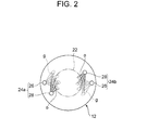
FIG. 2 is a side cross-sectional view of the dual-fuel diesel engine according to the above embodiment. -
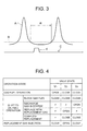
FIG. 3 is a diagram of a relationship between the pressure inside a combustion chamber and an injection timing of a replacement gas according to the above embodiment. -
FIG. 4 is a table of an operation procedure for performing injection of the replacement gas in the above embodiment. - Embodiments of the present invention will now be described in detail with reference to the accompanying drawings. It is intended, however, that unless particularly specified, dimensions, materials, shapes, relative positions and the like of components described in the embodiments shall be interpreted as illustrative only and not limitative of the scope of the present invention.
- An embodiment of a dual-fuel diesel engine to which the present invention is applied will be described in reference to
FIGs. 1 to 4 . The present embodiment is an example where the present invention is applied to a two-cycle dual-fuel diesel engine. - As illustrated in
FIG. 1 , a dual-fuel diesel engine 10 of the present embodiment includes acylinder 12 of a cylindrical shape, acylinder head 14 connected to the upper end of thecylinder 12, and apiston 16 housed inside thecylinder 12 so as to be freely reciprocable. A combustion chamber "c" is defined by the surroundingwall 12a of thecylinder 12, thecylinder head 14, and thetop face 16a of thepiston 16.piston rings 18 are disposed on the outer circumferential face of thepiston 16 so as to seal a gap between the outer circumferential face of thepiston 16 and the surroundingwall 12a of thecylinder 12. - On the surrounding
wall 12a at a bottom region of thecylinder 12, a plurality ofscavenging ports 20 are opened at equal intervals in the circumferential direction. Thescavenging ports 20 are formed above thetop face 16a of thepiston 16 being positioned in the region of the bottom dead center (as indicated by the double-dotted chain line in the drawing). Upon thepiston 16 being positioned in the region of the bottom dead center, air is supplied to the combustion chamber "c" from thescavenging ports 20. - Further, while an exhaust port opens at the center of the
cylinder head 14, anexhaust valve 22 is disposed on the exhaust port for opening and closing the exhaust port. In the scavenging stroke in which thepiston 16 ascends, thisexhaust valve 22 is kept open until thepiston 16 reaches the position of approximately 100° before top dead center. Then, the air supplied to the combustion chamber "c" from thescavenging ports 20 scavenges the exhaust gas from the previous stroke that has remained in the combustion chamber "c". - On the
cylinder head 14, a pair of dual-fuel injectors exhaust valve 22. The dual-fuel injectors cylinder 12 at an interval of 180° from each other. The dual-fuel injection devices gas fuel injector 26 that injects a gas fuel "g" such as natural gas to the combustion chamber "c" and apilot fuel injector 28 that similarly injects an oil fuel "o" having high compression-ignition properties to the combustion chamber "c". - The
gas fuel injectors 26 and thepilot fuel injectors 28 are connected to an engine control unit (ECU) 30 throughcables 32, so that theECU 12 controls fuel injecting operation. The ECU 30 is connected to acrank angle sensor 36 that detects a rotation angle of acrank shaft 34 through acable 38. TheECU 30 detects a phase of thepiston 16 by receiving a detection signal of a rotation angle of thecrank shaft 34 from thecrank angle sensor 36 through thecable 38. - The
gas fuel injectors 26 and thepilot fuel injectors 28 inject a gas fuel "g" and an oil fuel "o" into the combustion chamber "c" at a predetermined timing based on a signal transmitted from theECU 30. Upon thepiston 16 being in the vicinity of the top dead center (for instance, 0° to 100° before top dead center), thegas fuel injectors 26 and thepilot fuel injectors 28 inject the corresponding fuels nearly at the same time. In the combustion chamber "c" of high-temperature atmosphere, the oil fuel "o" having high compression-ignition properties self-ignites, which causes the gas fuel "g" injected nearly at the same time to combust so as to generate flame in the combustion chamber "c". - In the vicinity of the dual-
fuel diesel engine 10, an oilfuel reservoir tank 40, a gasfuel reservoir tank 42 and a replacementgas reservoir tank 44 are disposed. The oilfuel reservoir tank 40 is connected to theoil fuel injectors 28 of the dual-fuel injectors fuel supply path 46. Aliquid pump 48 is disposed in the oilfuel supply path 46. The gasfuel reservoir tank 42 is connected to thegas fuel injectors 26 of the dual-fuel injectors fuel supply path 50. An oil fuel is stored in the oilfuel reservoir tank 40, while a gas fuel such as natural gas is stored in a pressurized state in the gasfuel reservoir tank 42. - An electromagnetic opening-and-closing valve V1 is disposed in the gas
fuel supply path 50. The gasfuel supply path 50 is connected to the replacementgas reservoir tank 44 through a replacementgas supply path 52. The replacementgas supply path 52 is connected to the gasfuel supply path 50 at the downstream side relative to the electromagnetic opening-and-closing valve V1. In the replacementgas reservoir tank 44, an inert gas such as nitrogen gas or air is stored in a pressurized state as a replacement gas. Further, to the gasfuel supply path 50, anatmosphere introducing path 54 is connected at the downstream side relative to the connection point to the replacementgas supply path 52. An electromagnetic opening-and-closing valve V3 is disposed in theatmosphere introducing path 54. Theliquid pump 48 and the electromagnetic opening-and-closing valves V1 to V3 are connected to theECU 30 throughcables 56, so that theECU 30 controls their operations. - In such configuration, except in the extremely-low-load operating range, the dual-
fuel injectors gas fuel injectors 26 is stopped and only the oil fuel "o" is injected from the oil fuel injectors 28 (single combustion mode). - In
FIG. 3 , the line A represents the pressure of the combustion chamber "c", the line B represents the pressure of the replacement gas inside the replacementgas reservoir tank 44, and the line C represents the time when the replacement gas is injected from thegas fuel injectors 26. The replacement gas pressure inside the replacementgas reservoir tank 44 is kept constant. The time "d" when the replacement gas is injected from thegas fuel injectors 26 is selected to be in the time range R in which thepiston 16 is positioned in the region of the bottom dead center and the pressure of the combustion chamber "c" is lower than the pressure inside the replacementgas reservoir tank 44. - In the present embodiment, when shifting from the dual-fuel combustion mode to the single combustion mode, the
ECU 30 performs opening-and-closing operations for the electromagnetic opening-and-closing valves V1, V2 and V3 according to the procedure illustrated inFIG. 4 . In the drawing, during the dual-fuel combustion mode, theECU 30 controls the electromagnetic opening-and-closing valve V1 to be open and the electromagnetic opening-and-closing valves V2 and V3 to be closed. When shifting to the single combustion mode, the electromagnetic opening-and-closing valve V1 is closed so as to block the gas fuel. Then, the electromagnetic opening-and-closing valve V3 is opened to discharge the gas fuel remaining in the gasfuel supply path 50 to the outside of the system. - Next, the electromagnetic opening-and-closing valve V2 is opened to introduce the replacement gas from the replacement
gas reservoir tank 44 into the gasfuel supply path 50 so as to replace contents in the gasfuel supply path 50 with the replacement gas. After the replacement is completed, the electromagnetic opening-and-closing valves V2 and V3 are closed. Then, the electromagnetic opening-and-closing valve V2 is opened to inject the replacement gas from thegas fuel injectors 26. As a result, during the single combustion mode, it is possible to blow off combustion residues adhering to the nozzle holes of thegas fuel injectors 26 and thus to prevent blockage of the nozzle holes. - Next, in order to return to the dual combustion mode from this state, the electromagnetic opening-and-closing valve V2 is closed at first, and then the electromagnetic opening-and-closing valve V3 is opened so as to discharge the replacement gas inside the gas
fuel supply path 50 to the outside of the system. Then, the electromagnetic opening-and-closing valve V1 is opened to replace the contents of the gasfuel supply path 50 with the gas fuel. Further, the electromagnetic opening-and-closing valve V3 is closed to supply the gas fuel "g" to thegas fuel injectors 26. - According to the present embodiment, by injecting the replacement gas from the
gas fuel injectors 26 during operation in the single injection mode in which the oil fuel "o" is injected, it is possible to blow off the combustion residues adhering to the nozzle holes of thegas fuel injectors 26. As a result, it is possible to prevent blockage of the nozzle holes of thegas fuel injectors 26 and to shift from the single combustion mode to the dual combustion mode smoothly. Further, by injecting the replacement gas in the time range R in which thepiston 16 is positioned in the region of the bottom dead center and the pressure of the combustion chamber "c" is lower than the pressure inside the replacementgas reservoir tank 44, injection of the replacement gas is facilitated. - Still further, only by opening the electromagnetic opening-and-closing valve V2 by the
ECU 30, the replacement gas inside the inertgas reservoir tank 44 is injected from thegas fuel injectors 26 by its own pressure. Thus, there is no driving device needed for injecting the replacement gas, and thus the cost is reduced. Moreover, automation is enabled by a simple control mechanism where theECU 30 only controls the electromagnetic opening-and-closing valves V1, V2 and V3. Furthermore, upon switching between the dual combustion mode and the single combustion mode, it is possible to discharge the gas fuel or the replacement gas remaining in the gasfuel supply path 50 to the outside air from theatmosphere introducing path 54. As a result, the previously remaining gas is not injected from thegas fuel injectors 26 immediately after the switch, which makes it possible to smoothly switch to supplying the next gas. - While the present embodiment is an example where a pair of dual-
fuel injectors cylinder head 14, the present invention may be applied to the case where there is one dual-fuel injector, or there are three or more of the same. Further, while the present embodiment is an example where the present invention is applied to a two-cycle dual-fuel diesel engine, the present invention may be applied to a four-cycle dual-fuel diesel engine. - According to the present invention, during operation in the single combustion mode where only an oil fuel is injected, it is possible to prevent blockage of the nozzle holes of the gas fuel injectors and to smoothly shift from the single combustion mode to the dual combustion mode.
Claims (4)
- An operation method for a dual-fuel diesel engine configured to inject an oil fuel for ignition from a pilot fuel injector and inject a gas fuel from a gas fuel injector into a combustion chamber inside a cylinder, the method comprising:a first step of operating the dual-fuel diesel engine in a single combustion mode in which only the oil fuel is injected into the combustion chamber; anda second step of injecting a replacement gas from the gas fuel injector so as to remove combustion residues adhering to a nozzle hole of the gas fuel injector upon a pressure in the combustion chamber becoming lower than a supply pressure of the replacement gas during operation in the single injection mode.
- The operation method for a dual-fuel diesel engine according to claim 1,
wherein a replacement gas reservoir tank is connected to the gas fuel injector via a replacement gas supply path, and
wherein, in the second step, the replacement gas is injected into the combustion chamber from the replacement gas reservoir tank upon the pressure in the combustion chamber becoming lower than a pressure in the replacement gas reservoir tank. - A dual-fuel diesel engine comprising:a cylinder;a piston configured to reciprocate inside the cylinder;a cylinder head configured to define a combustion chamber with the cylinder;a pilot fuel injector configured to inject an oil fuel;a gas fuel injector configured to inject a gas fuel;an oil fuel supply device configured to supply the oil fuel to the pilot fuel injector;a gas fuel supply device configured to supply the gas fuel to the gas fuel injector;a replacement gas supply device configured to supply a replacement gas to the gas fuel injector;a piston position detection device configured to detect a position of the piston; anda controller configured to inject the replacement gas from the gas fuel injector upon a pressure in the combustion chamber becoming lower than a supply pressure of the replacement gas during operation in a single injection mode in which only the oil fuel is injected into the combustion chamber.
- The dual-fuel diesel engine according to claim 3,
wherein the gas fuel supply device includes a gas fuel reservoir tank connected to the gas fuel injector via a gas fuel supply path and a first opening-and-closing valve disposed in the gas fuel supply path,
wherein the replacement gas supply device includes a replacement gas reservoir tank connected to the gas fuel injector via a replacement gas fuel supply path that branches from the gas fuel supply path at a downstream side relative to the first opening-and-closing valve and a second opening-and-closing valve disposed in the replacement gas supply path,
wherein the dual-fuel diesel engine further includes an atmosphere introducing path that branches from the gas fuel supply path at a downstream side relative to a branch point where the replacement gas supply path branches and a third opening-and-closing valve disposed in the atmosphere introducing path, and
wherein the controller is configured capable of controlling each of the opening-and-closing valves.
Applications Claiming Priority (2)
| Application Number | Priority Date | Filing Date | Title |
|---|---|---|---|
| JP2012090234A JP5851918B2 (en) | 2012-04-11 | 2012-04-11 | Dual fuel diesel engine and operating method thereof |
| PCT/JP2013/052936 WO2013153844A1 (en) | 2012-04-11 | 2013-02-07 | Dual-fuel diesel engine and method for operating same |
Publications (2)
| Publication Number | Publication Date |
|---|---|
| EP2837803A1 true EP2837803A1 (en) | 2015-02-18 |
| EP2837803A4 EP2837803A4 (en) | 2015-11-18 |
Family
ID=49327424
Family Applications (1)
| Application Number | Title | Priority Date | Filing Date |
|---|---|---|---|
| EP13776253.0A Withdrawn EP2837803A4 (en) | 2012-04-11 | 2013-02-07 | Dual-fuel diesel engine and method for operating same |
Country Status (6)
| Country | Link |
|---|---|
| US (1) | US20150013638A1 (en) |
| EP (1) | EP2837803A4 (en) |
| JP (1) | JP5851918B2 (en) |
| KR (1) | KR101564867B1 (en) |
| CN (1) | CN104136749B (en) |
| WO (1) | WO2013153844A1 (en) |
Families Citing this family (13)
| Publication number | Priority date | Publication date | Assignee | Title |
|---|---|---|---|---|
| JP5765819B2 (en) * | 2012-04-11 | 2015-08-19 | 三菱重工業株式会社 | 2-cycle gas engine |
| US10465616B2 (en) * | 2013-08-05 | 2019-11-05 | Achates Power, Inc. | Dual-fuel constructions for opposed-piston engines with shaped combustion chambers |
| US9194344B1 (en) * | 2014-05-28 | 2015-11-24 | Electro-Motive Diesel, Inc. | Dual fuel engine having selective compression reduction |
| JP6320873B2 (en) * | 2014-08-07 | 2018-05-09 | 日野自動車株式会社 | Dual fuel engine and combustion method thereof |
| WO2016074091A1 (en) * | 2014-11-12 | 2016-05-19 | Verail Technologies, Inc. | Multi-fuel internal combustion engine, fuel systems and related methods |
| DK3121428T3 (en) * | 2015-05-19 | 2019-10-14 | Winterthur Gas & Diesel Ag | Process for operating a large diesel engine, using this method and large diesel engine |
| JP6645174B2 (en) * | 2015-12-22 | 2020-02-14 | 株式会社豊田自動織機 | Liquid fuel temperature control system for dual fuel diesel engine |
| EP3404235A1 (en) * | 2017-05-19 | 2018-11-21 | Winterthur Gas & Diesel AG | Large diesel motor and method for operating same |
| DE102017129028A1 (en) * | 2017-12-06 | 2019-06-06 | Man Energy Solutions Se | Dual-fuel engine and method of operating a dual-fuel engine |
| CN109931188B (en) * | 2019-02-18 | 2024-06-07 | 英嘉动力科技无锡有限公司 | Compression ignition type dual-fuel internal combustion engine system |
| JP2024143751A (en) | 2023-03-30 | 2024-10-11 | 株式会社ジャパンエンジンコーポレーション | Gas engine and its operating method |
| US12535041B2 (en) * | 2023-11-30 | 2026-01-27 | Caterpillar Inc. | Systems and methods for at-cylinder fuel switching |
| CN118564340B (en) * | 2024-06-03 | 2025-11-25 | 中船动力研究院有限公司 | A modular multi-fuel reserved low-carbon and zero-carbon dual-fuel engine |
Family Cites Families (12)
| Publication number | Priority date | Publication date | Assignee | Title |
|---|---|---|---|---|
| DE3219132C2 (en) | 1982-05-21 | 1985-11-21 | Karl Mayer Textil-Maschinen-Fabrik Gmbh, 6053 Obertshausen | Direct warping machine with a device for regulating the warping speed |
| NO823336L (en) * | 1982-10-04 | 1984-04-05 | Moss Rosenberg Verft As | DEVICE FOR DIOSTEL DIESEL ENGINE AND PROCEDURES FOR OPERATION OF TOSTOFFS DIESEL ENGINES |
| JPS604761U (en) * | 1983-06-23 | 1985-01-14 | 三井造船株式会社 | Arrangement structure of fuel injection valve in dual fuel engine |
| US6032617A (en) * | 1998-05-27 | 2000-03-07 | Caterpillar Inc. | Dual fuel engine which ignites a homogeneous mixture of gaseous fuel, air, and pilot fuel |
| US6705277B1 (en) * | 2000-07-13 | 2004-03-16 | Caterpillar Inc | Method and apparatus for delivering multiple fuel injections to the cylinder of an engine wherein the pilot fuel injection occurs during the intake stroke |
| US6550430B2 (en) * | 2001-02-27 | 2003-04-22 | Clint D. J. Gray | Method of operating a dual fuel internal |
| JP2003193874A (en) | 2001-12-26 | 2003-07-09 | Nippon Ekosu Kk | Dual fuel diesel engine combining gas fuel |
| JP4225276B2 (en) * | 2004-12-13 | 2009-02-18 | 三菱自動車工業株式会社 | Internal combustion engine |
| GB2447046B (en) * | 2007-02-28 | 2009-09-02 | Inspecs Ltd | Engine fuel supply system |
| JP4370586B2 (en) * | 2007-12-04 | 2009-11-25 | 明男 石田 | Dual operation mode engine system |
| CN101737176A (en) * | 2008-11-21 | 2010-06-16 | 深圳市沃尔奔达新能源股份有限公司 | Natural gas/diesel dual-fuel ECU electronic control injection system |
| US8844498B2 (en) * | 2010-11-11 | 2014-09-30 | Ge Oil & Gas Compression Systems, Llc | Positive displacement radical injection system |
-
2012
- 2012-04-11 JP JP2012090234A patent/JP5851918B2/en active Active
-
2013
- 2013-02-07 EP EP13776253.0A patent/EP2837803A4/en not_active Withdrawn
- 2013-02-07 CN CN201380010160.8A patent/CN104136749B/en active Active
- 2013-02-07 KR KR1020147026711A patent/KR101564867B1/en active Active
- 2013-02-07 WO PCT/JP2013/052936 patent/WO2013153844A1/en not_active Ceased
- 2013-02-07 US US14/383,684 patent/US20150013638A1/en not_active Abandoned
Also Published As
| Publication number | Publication date |
|---|---|
| CN104136749B (en) | 2017-03-01 |
| US20150013638A1 (en) | 2015-01-15 |
| JP5851918B2 (en) | 2016-02-03 |
| WO2013153844A1 (en) | 2013-10-17 |
| KR101564867B1 (en) | 2015-10-30 |
| CN104136749A (en) | 2014-11-05 |
| KR20140134686A (en) | 2014-11-24 |
| JP2013217337A (en) | 2013-10-24 |
| EP2837803A4 (en) | 2015-11-18 |
Similar Documents
| Publication | Publication Date | Title |
|---|---|---|
| US20150013638A1 (en) | Dual-fuel diesel engine and operation method of the same | |
| EP2837789A1 (en) | 2-cycle gas engine | |
| EP2837802A1 (en) | Dual-fuel diesel engine | |
| US10287969B2 (en) | Internal combustion engine and method for operating an internal combustion engine | |
| EP2857668A1 (en) | Fuel gas injection valve, dual-fuel gas engine, and fuel gas injection method | |
| EP2905450B1 (en) | Uniflow scavenging 2-cycle engine | |
| EP2860376B1 (en) | Two-stroke uniflow engine | |
| EP2891780B1 (en) | Uniflow scavenging two-cycle engine | |
| US20160252011A1 (en) | Two-cycle gas engine | |
| KR102261412B1 (en) | Method of supplying fuel to engine | |
| KR101864971B1 (en) | Gas fuel supply system and method for detecting abnormality of gas fuel supply system | |
| JP2012036780A (en) | Two-stroke gas engine | |
| EP2921675A1 (en) | Diesel engine control device, diesel engine, and diesel engine control method | |
| KR102580971B1 (en) | Method of operating a large diesel engine, use of this method, as well as large diesel engine | |
| KR101978012B1 (en) | Fuel injection system | |
| CN112368470A (en) | Method for increasing the load in a four-stroke internal combustion engine | |
| KR20150060973A (en) | Diesel engine control device, diesel engine, and diesel engine control method | |
| JP2014101884A (en) | Two-stroke gas engine | |
| JP2021181783A (en) | Internal combustion engine | |
| JP2011220284A (en) | Engine control device | |
| EP4675099A1 (en) | Engine | |
| KR102611647B1 (en) | Internal combustion engine |
Legal Events
| Date | Code | Title | Description |
|---|---|---|---|
| PUAI | Public reference made under article 153(3) epc to a published international application that has entered the european phase |
Free format text: ORIGINAL CODE: 0009012 |
|
| 17P | Request for examination filed |
Effective date: 20140915 |
|
| AK | Designated contracting states |
Kind code of ref document: A1 Designated state(s): AL AT BE BG CH CY CZ DE DK EE ES FI FR GB GR HR HU IE IS IT LI LT LU LV MC MK MT NL NO PL PT RO RS SE SI SK SM TR |
|
| AX | Request for extension of the european patent |
Extension state: BA ME |
|
| DAX | Request for extension of the european patent (deleted) | ||
| RA4 | Supplementary search report drawn up and despatched (corrected) |
Effective date: 20151019 |
|
| RIC1 | Information provided on ipc code assigned before grant |
Ipc: F02B 77/04 20060101ALI20151013BHEP Ipc: F02D 41/30 20060101ALI20151013BHEP Ipc: F02M 61/14 20060101ALI20151013BHEP Ipc: F02D 19/08 20060101AFI20151013BHEP Ipc: F02B 25/04 20060101ALI20151013BHEP Ipc: F02D 41/00 20060101ALI20151013BHEP Ipc: F02D 19/10 20060101ALI20151013BHEP Ipc: F02D 41/38 20060101ALI20151013BHEP Ipc: F02D 19/06 20060101ALI20151013BHEP Ipc: F02D 35/02 20060101ALI20151013BHEP Ipc: F02D 19/12 20060101ALI20151013BHEP |
|
| STAA | Information on the status of an ep patent application or granted ep patent |
Free format text: STATUS: THE APPLICATION HAS BEEN WITHDRAWN |
|
| 18W | Application withdrawn |
Effective date: 20160622 |