EP2837796A1 - Method for manufacturing coupled turbine blades, and coupled turbine blades - Google Patents
Method for manufacturing coupled turbine blades, and coupled turbine blades Download PDFInfo
- Publication number
- EP2837796A1 EP2837796A1 EP13775470.1A EP13775470A EP2837796A1 EP 2837796 A1 EP2837796 A1 EP 2837796A1 EP 13775470 A EP13775470 A EP 13775470A EP 2837796 A1 EP2837796 A1 EP 2837796A1
- Authority
- EP
- European Patent Office
- Prior art keywords
- fabric
- fabrics
- vanes
- section
- vane
- Prior art date
- Legal status (The legal status is an assumption and is not a legal conclusion. Google has not performed a legal analysis and makes no representation as to the accuracy of the status listed.)
- Granted
Links
Images




Classifications
-
- F—MECHANICAL ENGINEERING; LIGHTING; HEATING; WEAPONS; BLASTING
- F01—MACHINES OR ENGINES IN GENERAL; ENGINE PLANTS IN GENERAL; STEAM ENGINES
- F01D—NON-POSITIVE DISPLACEMENT MACHINES OR ENGINES, e.g. STEAM TURBINES
- F01D9/00—Stators
- F01D9/02—Nozzles; Nozzle boxes; Stator blades; Guide conduits, e.g. individual nozzles
-
- F—MECHANICAL ENGINEERING; LIGHTING; HEATING; WEAPONS; BLASTING
- F01—MACHINES OR ENGINES IN GENERAL; ENGINE PLANTS IN GENERAL; STEAM ENGINES
- F01D—NON-POSITIVE DISPLACEMENT MACHINES OR ENGINES, e.g. STEAM TURBINES
- F01D5/00—Blades; Blade-carrying members; Heating, heat-insulating, cooling or antivibration means on the blades or the members
- F01D5/12—Blades
- F01D5/22—Blade-to-blade connections, e.g. for damping vibrations
- F01D5/225—Blade-to-blade connections, e.g. for damping vibrations by shrouding
-
- F—MECHANICAL ENGINEERING; LIGHTING; HEATING; WEAPONS; BLASTING
- F01—MACHINES OR ENGINES IN GENERAL; ENGINE PLANTS IN GENERAL; STEAM ENGINES
- F01D—NON-POSITIVE DISPLACEMENT MACHINES OR ENGINES, e.g. STEAM TURBINES
- F01D5/00—Blades; Blade-carrying members; Heating, heat-insulating, cooling or antivibration means on the blades or the members
- F01D5/12—Blades
- F01D5/28—Selecting particular materials; Particular measures relating thereto; Measures against erosion or corrosion
- F01D5/282—Selecting composite materials, e.g. blades with reinforcing filaments
-
- F—MECHANICAL ENGINEERING; LIGHTING; HEATING; WEAPONS; BLASTING
- F01—MACHINES OR ENGINES IN GENERAL; ENGINE PLANTS IN GENERAL; STEAM ENGINES
- F01D—NON-POSITIVE DISPLACEMENT MACHINES OR ENGINES, e.g. STEAM TURBINES
- F01D9/00—Stators
- F01D9/02—Nozzles; Nozzle boxes; Stator blades; Guide conduits, e.g. individual nozzles
- F01D9/04—Nozzles; Nozzle boxes; Stator blades; Guide conduits, e.g. individual nozzles forming ring or sector
- F01D9/042—Nozzles; Nozzle boxes; Stator blades; Guide conduits, e.g. individual nozzles forming ring or sector fixing blades to stators
-
- F—MECHANICAL ENGINEERING; LIGHTING; HEATING; WEAPONS; BLASTING
- F05—INDEXING SCHEMES RELATING TO ENGINES OR PUMPS IN VARIOUS SUBCLASSES OF CLASSES F01-F04
- F05D—INDEXING SCHEME FOR ASPECTS RELATING TO NON-POSITIVE-DISPLACEMENT MACHINES OR ENGINES, GAS-TURBINES OR JET-PROPULSION PLANTS
- F05D2230/00—Manufacture
- F05D2230/50—Building or constructing in particular ways
-
- F—MECHANICAL ENGINEERING; LIGHTING; HEATING; WEAPONS; BLASTING
- F05—INDEXING SCHEMES RELATING TO ENGINES OR PUMPS IN VARIOUS SUBCLASSES OF CLASSES F01-F04
- F05D—INDEXING SCHEME FOR ASPECTS RELATING TO NON-POSITIVE-DISPLACEMENT MACHINES OR ENGINES, GAS-TURBINES OR JET-PROPULSION PLANTS
- F05D2300/00—Materials; Properties thereof
- F05D2300/60—Properties or characteristics given to material by treatment or manufacturing
- F05D2300/601—Fabrics
-
- F—MECHANICAL ENGINEERING; LIGHTING; HEATING; WEAPONS; BLASTING
- F05—INDEXING SCHEMES RELATING TO ENGINES OR PUMPS IN VARIOUS SUBCLASSES OF CLASSES F01-F04
- F05D—INDEXING SCHEME FOR ASPECTS RELATING TO NON-POSITIVE-DISPLACEMENT MACHINES OR ENGINES, GAS-TURBINES OR JET-PROPULSION PLANTS
- F05D2300/00—Materials; Properties thereof
- F05D2300/60—Properties or characteristics given to material by treatment or manufacturing
- F05D2300/603—Composites; e.g. fibre-reinforced
- F05D2300/6033—Ceramic matrix composites [CMC]
-
- Y—GENERAL TAGGING OF NEW TECHNOLOGICAL DEVELOPMENTS; GENERAL TAGGING OF CROSS-SECTIONAL TECHNOLOGIES SPANNING OVER SEVERAL SECTIONS OF THE IPC; TECHNICAL SUBJECTS COVERED BY FORMER USPC CROSS-REFERENCE ART COLLECTIONS [XRACs] AND DIGESTS
- Y02—TECHNOLOGIES OR APPLICATIONS FOR MITIGATION OR ADAPTATION AGAINST CLIMATE CHANGE
- Y02T—CLIMATE CHANGE MITIGATION TECHNOLOGIES RELATED TO TRANSPORTATION
- Y02T50/00—Aeronautics or air transport
- Y02T50/60—Efficient propulsion technologies, e.g. for aircraft
-
- Y—GENERAL TAGGING OF NEW TECHNOLOGICAL DEVELOPMENTS; GENERAL TAGGING OF CROSS-SECTIONAL TECHNOLOGIES SPANNING OVER SEVERAL SECTIONS OF THE IPC; TECHNICAL SUBJECTS COVERED BY FORMER USPC CROSS-REFERENCE ART COLLECTIONS [XRACs] AND DIGESTS
- Y10—TECHNICAL SUBJECTS COVERED BY FORMER USPC
- Y10T—TECHNICAL SUBJECTS COVERED BY FORMER US CLASSIFICATION
- Y10T29/00—Metal working
- Y10T29/49—Method of mechanical manufacture
- Y10T29/49316—Impeller making
- Y10T29/4932—Turbomachine making
- Y10T29/49321—Assembling individual fluid flow interacting members, e.g., blades, vanes, buckets, on rotary support member
-
- Y—GENERAL TAGGING OF NEW TECHNOLOGICAL DEVELOPMENTS; GENERAL TAGGING OF CROSS-SECTIONAL TECHNOLOGIES SPANNING OVER SEVERAL SECTIONS OF THE IPC; TECHNICAL SUBJECTS COVERED BY FORMER USPC CROSS-REFERENCE ART COLLECTIONS [XRACs] AND DIGESTS
- Y10—TECHNICAL SUBJECTS COVERED BY FORMER USPC
- Y10T—TECHNICAL SUBJECTS COVERED BY FORMER US CLASSIFICATION
- Y10T29/00—Metal working
- Y10T29/49—Method of mechanical manufacture
- Y10T29/49316—Impeller making
- Y10T29/49336—Blade making
- Y10T29/49337—Composite blade
Definitions
- the present invention relates to coupled vanes of a turbine applied to an aeronautic engine for example, and a method of production thereof.
- FIG. 13(a) is a general perspective view of a typical aeronautic turbofan engine and FIG. 13(b) is a general perspective view in which a part of its turbine rotor vanes is enlarged, because a strong centrifugal force C acts on the turbine rotor vane, the turbine rotor vane is in general produced from any of Ni-based alloys or such. Further, as shown in FIG.
- a turbine rotor vane 70 has a complex shape comprising a vane section 72, a platform section 74 elongated in a vertical direction relative to faces of the vane, a dovetail section 76 disposed at one end of the vane section 72, and a tip shroud section 78 elongated in a vertical direction relative to the faces of the vane at another end, it is readily produced by casting a metal material such as a Ni-based alloy.
- the similar applies to turbine stator vanes and any of them has a complex shape but is readily produced by using a metal material such as a Ni-based alloy.
- Turbine vanes may be used either as single vanes or as coupled vanes.
- tip shroud sections are mutually joined, thereby being made into coupled vanes.
- a shroud section (outer band section) and a platform section (inner band section) of each vane may be respectively joined to these counterparts so that coupled vanes are made, or coupled vanes are integrally formed by casting.
- FIG. 13(c) is a schematic perspective view depicting a turbine rotor vane of a coupled-vane structure, in which a coupled-vane 80 is comprised of vane sections 82, platform sections 84 elongated in vertical directions relative to faces of the vanes, dovetail sections 86 disposed at one ends of the vane sections 82, and tip shroud sections 88 elongated in vertical directions relative to the faces of the vanes at another ends.
- its shape comes to be more complex but can be produced by using an advanced mold.
- Ceramic matrix composites each of which is comprised of a ceramic fiber fabric and a ceramic matrix, are expected to be applied to turbine vanes.
- Ceramic matrix composites are superior in light of weight and thermal resistance, if they can be used as turbine vanes, it could be expected to reduce weight of engines and reduce fuel consumption rates.
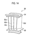
- FIG. 14 is that in which four turbine stator vanes are coupled and the turbine stator vane 90 of a coupled-vane structure is comprised of vane sections 92a, 92b, 92c, 92d, an outer band section 94 and an inner band section 96 respectively elongated in vertical directions relative to faces of the vanes.
- vane sections 92a, 92b, 92c and 92d to the outer band section 94 and the inner band section 96 applied is adhesive to bond them or they are mechanically connected.
- a method for producing coupled vanes of a turbine having an axis is comprised of: arranging a plurality of first fabrics of ceramic fibers in radial directions relative to the axis to form a plurality of vane sections; arranging a second fabric of the ceramic fibers in a circumferential direction relative to the axis; connecting the first fabrics with the second fabric by bending and laying first ends of the first fabrics on the second fabric in parallel; incorporating the first fabrics connected with the second fabric into a mold to mold the first and second fabrics into a unitary body; and impregnating the plurality of first fabrics and the second fabric molded into the unitary body with a matrix.
- coupled vanes of a turbine having an axis are comprised of: a plurality of vane sections comprising a plurality of first fabrics of ceramic fibers arranged in radial directions relative to the axis; and a tip shroud section or an outer band section, wherein a second fabric of the ceramic fibers is arranged in a circumferential direction relative to the axis, wherein the first fabrics are connected with the second fabric by bending and laying first ends of the first fabrics on the second fabric in parallel, wherein the first and second fabrics are molded into a unitary body by incorporating the first fabrics connected with the second fabric into a mold, and wherein the plurality of first fabrics and the second fabric molded into the unitary body is impregnated with a matrix.
- first and second fabrics are, after being overlapped in parallel, impregnated with the matrix so that fibers thereof overlap each other and then join together, coupled vanes of a turbine are produced with sufficient strength.
- a composite member in which a plurality of members of a ceramic composite material is joined together can be produced, and, as a composite member produced thereby exemplified are coupled vanes in which a plurality of rotor vanes or stator vanes of a turbine is combined.
- fabrics for vane sections and a fabric for a connecting section are prepared, and the plural fabrics of the vane sections are joined by the fabric for the connecting section, and are thereafter incorporated into a mold and molded into a unitary body, and an obtained molded body is impregnated with a ceramic matrix, thereby producing the coupled vanes.
- the connecting section is a tip shroud section
- stator vanes the connecting section is an outer band section.
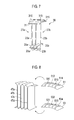
- FIG. 1 (a) is a schematic perspective view for illustrating the coupled vanes for the rotor vanes in accordance with one embodiment of the present invention.
- the coupled vanes 1 for the rotor vanes according to the present embodiment include a plurality (two, exemplified in FIG. 1(a) ) of vane sections.
- the coupled vanes 1 for the rotor vanes according to the present embodiment as shown in FIG. 1(a) are comprised of two vane sections 2a,2b elongated in radial directions relative to an axis of the turbine, platform sections 3a,3b elongated in vertical directions relative to these vane faces (in a circumferential direction relative to the axis of the turbine), and dovetail sections 4a,4b arranged in one ends of the vane sections 2a,2b.
- two vane sections 2a,2b are connected at another ends thereof by a single tip shroud section 5.
- the coupled vanes 1 for the rotor vanes according to the present embodiment are comprised of the plurality of rotor vanes having similar shapes of rotor vanes of the prior art
- the coupled vanes 1 differ from those of the prior art in that the single tip shroud section unitarily connects the plurality of rotor vanes together.
- the dovetail sections 4a,4b of the coupled vanes 1 for the rotor vanes as described are made fit in a disk and, when the disk rotates, strong centrifugal force acts thereon in longitudinal directions of the vane sections 2a,2b.
- the respective fabrics are of a ceramic fabric
- the coupled vanes 1 are produced by, after connecting two fabrics constituting two vane sections 2a,2b (the fabric for the vane sections) by the fabric constituting the tip shroud section 5 (the fabric for the connecting section), incorporating them into a mold and molding them into a unitary body, impregnating the obtained molded body with the ceramic matrix, and fibers therein overlap each other, connection strength among the respective members (among the vane sections 2 and the tip shroud section 5 for example) is high, and therefore the coupled vanes 1 in use can be proof against high load (centrifugal force or such).
- coupled vanes 1 according to the present embodiment exemplified in FIG. 1(a) have two vane sections, the number of the vane sections in the present embodiment is not particularly limited.
- the coupled vanes 1 according to the present embodiment may include two or more vane sections.
- the present embodiment can be applied to turbine stator vanes in which the connecting sections are inner band sections or outer band sections.
- the connecting sections may be both the outer band sections and the inner band sections.
- the coupled vanes according to the present embodiment may have two connecting sections, one as the outer band sections and the other as the inner band sections.
- FIG. 1(b) is a schematic perspective view for illustrating the coupled vanes for the stator vanes in accordance with the present embodiment.
- the coupled vanes 11 for the stator vanes according to the present embodiment include a plurality of (four, exemplified in FIG. 1(b) ) vane sections.
- the coupled vanes 11 according to the present embodiment shown in FIG. 1(b) are comprised of four vane sections 12a,12b,12c,12d, which are mutually connected at these one ends and the other ends by the outer band section 15 and the inner band section 16.
- the coupled vanes 11 for the stator vanes according to the present embodiment exemplified in FIG. 1(b) are of ceramic fibers, and the coupled vanes 11 are produced by, after connecting four fabrics constituting four vane sections 12a,12b,12c,12d (the fabrics for the vane sections) by the fabrics constituting the outer band section 15 (the fabrics for the connecting sections) and the inner band section 16, incorporating them into a mold and molding them into a unitary body, and impregnating the obtained molded body with the ceramic matrix.
- connection strength among the respective members is high and therefore the coupled vanes 11 in use can be proof against high load.
- the coupled vanes 11 according to the present embodiment exemplified in FIG. 1(b) have four vane sections, the number of the vane sections in the present embodiment is not particularly limited.
- the coupled vanes 11 according to the present embodiment may include two or more vane sections, and may include still more vane sections, the number of which is four for example.
- the production method for the composite members according to the present embodiment can be applied to the production of the coupled vanes used as turbine vanes.
- the method is a method for producing a ceramic matrix composite member, which is comprised of preparing the fabric(s) for the connecting section(s) and a plurality of fabrics for the vane sections, a step of connecting the plural fabrics of the vane sections by the fabric(s) for the connecting section(s), a step of molding by incorporating the connected fabrics body into a mold and molding it into a unitary body to obtain a molded body, and a step of impregnating by impregnating the molded body with a matrix.
- fibers in the respective fabrics are made to overlap each other and are thereafter impregnated with the matrix.
- the step of connecting in the production method according to the present embodiment is a step of, based on the step of preparing the fabric(s) for the connecting section(s) and the plurality of fabrics for the vane sections, connecting the plurality of fabrics for the vane sections by the fabric for the connecting section to obtain a fabric-connected body.
- the step of connecting in a case for obtaining the coupled vanes for the rotor vanes according to the present embodiment and the step of connecting in a case for obtaining the coupled vanes for the stator vanes according to the present embodiment, based on the production method according to the present embodiment, will be respectively described below.
- the respective fabrics described below consist essentially of ceramic fibers, and more specifically fabrics without being impregnated with a matrix before the step of impregnating can be used. Or the fabrics may be partially or totally impregnated with the matrix in advance.
- FIG. 2 (a) and (b) is a drawing showing a fabric 21 in which a fabric 23 of ceramic fibers, which is to be a vane section and a dovetail section, is continuous with a fabric 25 of the ceramic fibers, which is to be a platform section, wherein FIG. 2(a) is a schematic side view and FIG. 2(b) is a sectional view taken from the line A-A in FIG. 2(a) .
- the fabric 21 is a three-dimensional fabric that is three-dimensionally woven to have a considerable thickness as shown in FIG. 2(b) . Its lower end is a part to be the dovetail section and the fabric is so woven to, just above it, branch into three parts.
- the center of these three branching parts is a part to be the vane section, and those along both sides thereof are a pair of fabrics 25 in flange-like shapes, which are to be the platform section.
- the pair of fabrics 25 is so woven to be a shape adapted for overlapping each other when being bent as described later.
- the part to be the vane section is so woven to further branch into two parts at its upper portion. While the fabric 21 is a three-dimensional fabric, the totality of which is a unitary body, the fabric 21 may be formed by overlapping and sewing a plurality of fabrics together.
- the pair of fabrics 25 of the ceramic fibers to be the platform section is respectively bent in a desired angle (about 90 degrees in a case of a turbine rotor) so that the fabrics 25 overlap each other in parallel and these fibers overlap and get close contact with each other. Thereby the fabrics 25 connect together.
- Parts 251 which are to be two platform sections and where the fabrics 25 overlap each other may be stitched together. It is advantageous in further increasing strength of the obtained fabric for the vane section.
- a fabric 27 for the vane section of an embodiment shown in FIG. 3(b) is obtained in a away described above.
- the fabrics 27 for the vane sections are, in a way as shown in FIGs. 4 , 5 , 6 and 7 , connected with a fabric 31 for the connecting section which will constitute the tip shroud section.
- the fabric for the connecting section is a generally rectangular fabric and is formed to have two through-holes allowing passage of one ends of the fabrics 27 for the vane sections.
- the through-holes can be formed by any known method such as machining.
- While the fabric 31 for the connecting section has two through-holes 311,312, one ends of the fabrics 27 for the vane sections is made to pass through these through-holes. After respectively having ends of two fabrics 27a,27b for the vane sections to pass through the through holes 311,312, as shown in FIG. 6 , parts passing therethrough are bent so as to become the connecting section.
- the other members 315 may be as shown in FIG. 6 added thereto, and a fabric connected body 38 as shown in FIG. 7 can be obtained. To put the bent ends between the fabric 31 for the connecting section and the other members 315 contributes to improvement of strength.
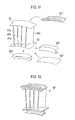
- FIG. 8 is a schematic drawing showing four fabrics 47a,47b,47c,47d, which will constitute the vane section, a fabric 51 for the connecting section, which will constitute the outer band section, and a fabric 53 for the connecting section, which will constitute the inner band section.
- the fabric 51 for the connecting section, which will constitute the outer band section, and the fabric 53 for the connecting section, which will constitute the inner band section, are in general rectangular fabrics and are formed to have through holes which allow passage of ends of the respective fabrics 47a,47b,47c,47d for the vane sections as described later.
- a plurality of fabrics 47 for the vane sections is prepared and, in a way as shown in FIG. 9 , connected with the fabrics 51,53 for the connecting section.
- the fabrics 51,53 respectively have four through holes 511,512,513,514 and 531,532,533,534, and the ends of the fabrics 47 for the vane sections are made to pass through the through-holes.
- the parts passing therethrough are, as shown in FIG. 10 , bent so as to become the connecting section later.
- the other members 516,517 and 536,537 may be added thereto and then the fabric connected body 58 as shown in FIG. 12 is obtained.
- the fabrics for the vane sections and the fabrics for the connecting sections as described above can be produced by a known method, and a fabric of a three-dimensional structure can be used.
- the fabric of the three-dimensional structure is, for example, obtained by bundling several hundred through several thousand of ceramic fibers to form a bundle of fibers, and weaving the bundle of fibers in X-,Y-,Z-directions.
- a fabric of a three-dimensional structure is obtained by, after obtaining a plurality of layers in which the bundle of fibers is arranged in the X-direction and the bundle of fibers is arranged in the Y-direction perpendicular thereto, overlaying these layers on each other and sewing them with the other bundle of fibers in a thickness direction (Z-direction). Processing is, if necessary, thereafter achieved to obtain the fabrics for the vane sections and the fabric for the connecting section in desired shapes.
- the fabrics for the vane sections and the fabric for the connecting section may be those having a three-directional structure or may be those partially not having a three-directional structure.
- Ceramic fibers of SiC, C, Si 3 N 4 , Al 2 O 3 or BN can be used. Further, the diameter of the ceramic fibers may be similar to that of the known ceramic fibers and may be about several through several tens micrometers for example.
- the step of molding in the production method according to the present embodiment is a step of incorporating the fabric connected body into a mold and molding it into a unitary body to obtain a molded body.
- the fabric connected body obtained by the step of connecting as described above is incorporated into a mold and then molded.
- the fabric connected body is incorporated and then molded.
- Internal shape of the mold is complementary to a shape of the desired molded body, and, by deforming the fabric connected body along the mold, the fabric connected body can be, inside the mold, molded into a unitary body.
- the step of impregnating is a step of impregnating the molded body with the matrix.
- a ceramic matrix is formed in the molded body by methods such as a step of chemical reaction from a gas or a step of pouring solid powder into the molded body and sintering it.
- the method exemplified is, for example, a method of exposing the molded body made to be the unitary body to ingredient gases in a chamber and depositing the matrix by chemical reaction onto surfaces of the molded body, or a method of impregnating the molded body made to be the unitary body with a substance (precursor), in which an ingredient powder solid is made to be slurry-like, and sintering it.
- a substance precursor
- the ceramic matrix composite in accordance with the present embodiment can be obtained in a way as described above.
- fibers in one member go over the connecting part to reach the other member (the tip shroud section for example) and overlap with fibers in the other member, and thereby both these members are connected by the matrix. More specifically, the fibers are not discontinuous at the connecting part and both these fibers are, with considerable overlapping, connected together. Even when a force is applied to the connecting part, because the fibers extending beyond the connecting part reinforce it, sufficient strength comparable to that at the other parts can be expected.
- the respective fabrics are still sufficiently flexible and can be therefore freely bent so as to have the fibers therein to get sufficiently close contact with each other, thereby enabling strong connection.
- Coupled vanes for a turbine with sufficient strength and its production method are provided.
Landscapes
- Engineering & Computer Science (AREA)
- Mechanical Engineering (AREA)
- General Engineering & Computer Science (AREA)
- Chemical & Material Sciences (AREA)
- Materials Engineering (AREA)
- Composite Materials (AREA)
- Turbine Rotor Nozzle Sealing (AREA)
Abstract
Description
- The present invention relates to coupled vanes of a turbine applied to an aeronautic engine for example, and a method of production thereof.
- On a turbine vane as one of components of a jet engine for example, in use, acts an intense stress due to strong centrifugal force or gas flow. Since particularly high strength as well as thermal resistance is therefore necessary for such a turbine vane, metal materials are generally used for production. While
FIG. 13(a) is a general perspective view of a typical aeronautic turbofan engine andFIG. 13(b) is a general perspective view in which a part of its turbine rotor vanes is enlarged, because a strong centrifugal force C acts on the turbine rotor vane, the turbine rotor vane is in general produced from any of Ni-based alloys or such. Further, as shown inFIG. 13(b) , although aturbine rotor vane 70 has a complex shape comprising avane section 72, a platform section 74 elongated in a vertical direction relative to faces of the vane, adovetail section 76 disposed at one end of thevane section 72, and atip shroud section 78 elongated in a vertical direction relative to the faces of the vane at another end, it is readily produced by casting a metal material such as a Ni-based alloy. The similar applies to turbine stator vanes and any of them has a complex shape but is readily produced by using a metal material such as a Ni-based alloy. - Turbine vanes may be used either as single vanes or as coupled vanes. In a case of rotor vanes, tip shroud sections are mutually joined, thereby being made into coupled vanes. In a case of stator vanes, a shroud section (outer band section) and a platform section (inner band section) of each vane may be respectively joined to these counterparts so that coupled vanes are made, or coupled vanes are integrally formed by casting.
FIG. 13(c) is a schematic perspective view depicting a turbine rotor vane of a coupled-vane structure, in which a coupled-vane 80 is comprised ofvane sections 82,platform sections 84 elongated in vertical directions relative to faces of the vanes,dovetail sections 86 disposed at one ends of thevane sections 82, andtip shroud sections 88 elongated in vertical directions relative to the faces of the vanes at another ends. In this case, its shape comes to be more complex but can be produced by using an advanced mold. - And, in recent years, ceramic matrix composites (CMC), each of which is comprised of a ceramic fiber fabric and a ceramic matrix, are expected to be applied to turbine vanes. As ceramic matrix composites are superior in light of weight and thermal resistance, if they can be used as turbine vanes, it could be expected to reduce weight of engines and reduce fuel consumption rates.
- Some proposals for turbine vanes to which ceramic matrix composites are applied and production methods have been so far brought forward. Further there have been proposals for turbine vanes of coupled-vane structures exemplified in
FIG. 14 (see thePTL 1 or 2 for example).FIG. 14 is that in which four turbine stator vanes are coupled and theturbine stator vane 90 of a coupled-vane structure is comprised ofvane sections outer band section 94 and aninner band section 96 respectively elongated in vertical directions relative to faces of the vanes. Among these fourvane sections outer band section 94 and theinner band section 96 applied is adhesive to bond them or they are mechanically connected. -
- PTL 1:
US Patent 6648597 - PTL 2: Japanese Patent Application Laid-open No.
H07-189607 - The cause that ceramic matrix composites exhibit high strength largely depends on reinforcement fibers in matrixes. Interfaces of adhesion or mechanical joining, however, render reinforcement fibers cut there and are therefore prominently inferior in strength as compared with regions where the fibers are continuous. If some reinforcement members were added in order to assure strength, the quality of lightweight as an advantage of the ceramic matrix composites would be impaired. The present invention has been achieved in light of these problems.
- According to a first aspect of the present invention, a method for producing coupled vanes of a turbine having an axis is comprised of: arranging a plurality of first fabrics of ceramic fibers in radial directions relative to the axis to form a plurality of vane sections; arranging a second fabric of the ceramic fibers in a circumferential direction relative to the axis; connecting the first fabrics with the second fabric by bending and laying first ends of the first fabrics on the second fabric in parallel; incorporating the first fabrics connected with the second fabric into a mold to mold the first and second fabrics into a unitary body; and impregnating the plurality of first fabrics and the second fabric molded into the unitary body with a matrix.
- According to a second aspect of the present invention, coupled vanes of a turbine having an axis are comprised of: a plurality of vane sections comprising a plurality of first fabrics of ceramic fibers arranged in radial directions relative to the axis; and a tip shroud section or an outer band section, wherein a second fabric of the ceramic fibers is arranged in a circumferential direction relative to the axis, wherein the first fabrics are connected with the second fabric by bending and laying first ends of the first fabrics on the second fabric in parallel, wherein the first and second fabrics are molded into a unitary body by incorporating the first fabrics connected with the second fabric into a mold, and wherein the plurality of first fabrics and the second fabric molded into the unitary body is impregnated with a matrix.
- Because the first and second fabrics are, after being overlapped in parallel, impregnated with the matrix so that fibers thereof overlap each other and then join together, coupled vanes of a turbine are produced with sufficient strength.
-
-
FIG. 1(a) is a schematic perspective view illustrating coupled vanes applied to rotor vanes in accordance with an embodiment of the present invention, andFIG. 1(b) is a schematic perspective view illustrating coupled vanes applied to stator vanes in accordance with the embodiment. -
FIG. 2 is a schematic drawing illustrating a connecting step for obtaining the coupled vanes applied to the rotor vanes in accordance with the embodiment. -
FIG. 3 is another schematic drawing illustrating the connecting step for obtaining the coupled vanes applied to the rotor vanes in accordance with the embodiment. -
FIG. 4 is still another schematic drawing illustrating the connecting step for obtaining the coupled vanes applied to the rotor vanes in accordance with the embodiment. -
FIG. 5 is further still another schematic drawing illustrating the connecting step for obtaining the coupled vanes applied to the rotor vanes in accordance with the embodiment. -
FIG. 6 is further still another schematic drawing illustrating the connecting step for obtaining the coupled vanes applied to the rotor vanes in accordance with the embodiment. -
FIG. 7 is further still another schematic drawing illustrating the connecting step for obtaining the coupled vanes applied to the rotor vanes in accordance with the embodiment. -
FIG. 8 is a schematic drawing illustrating a connecting step for obtaining the coupled vanes applied to the stator vanes in accordance with the embodiment. -
FIG. 9 is another schematic drawing illustrating the connecting step for obtaining the coupled vanes applied to the stator vanes in accordance with the embodiment. -
FIG. 10 is still another schematic drawing illustrating the connecting step for obtaining the coupled vanes applied to the stator vanes in accordance with the embodiment. -
FIG. 11 is still another schematic drawing illustrating the connecting step for obtaining the coupled vanes applied to the stator vanes in accordance with the embodiment. -
FIG. 12 is still another schematic drawing illustrating the connecting step for obtaining the coupled vanes applied to the stator vanes in accordance with the embodiment. -
FIG. 13(a) is a schematic perspective view of an aeronautic turbofan engine according to the prior art,FIG. 13(b) is a schematic perspective view in which a part of its turbine rotor vanes is enlarged, andFIG. 13(c) is a schematic perspective view in which turbine rotor vanes of a coupled-vane structure are enlarged. -
FIG. 14 is a schematic perspective view illustrating turbine rotor vanes of a coupled-vane structure according to the prior art. - Exemplary embodiments of the present invention will be described hereinafter with reference to the appended drawings.
- According to the respective embodiments, a composite member in which a plurality of members of a ceramic composite material is joined together can be produced, and, as a composite member produced thereby exemplified are coupled vanes in which a plurality of rotor vanes or stator vanes of a turbine is combined. From a ceramic fabric, fabrics for vane sections and a fabric for a connecting section are prepared, and the plural fabrics of the vane sections are joined by the fabric for the connecting section, and are thereafter incorporated into a mold and molded into a unitary body, and an obtained molded body is impregnated with a ceramic matrix, thereby producing the coupled vanes. In a case of rotor vanes, the connecting section is a tip shroud section, and, in a case of stator vanes, the connecting section is an outer band section.
-
FIG. 1 (a) is a schematic perspective view for illustrating the coupled vanes for the rotor vanes in accordance with one embodiment of the present invention. - As shown in
FIG. 1(a) , the coupledvanes 1 for the rotor vanes according to the present embodiment include a plurality (two, exemplified inFIG. 1(a) ) of vane sections. The coupledvanes 1 for the rotor vanes according to the present embodiment as shown inFIG. 1(a) are comprised of twovane sections platform sections dovetail sections vane sections vane sections tip shroud section 5. More specifically, whereas the coupledvanes 1 for the rotor vanes according to the present embodiment are comprised of the plurality of rotor vanes having similar shapes of rotor vanes of the prior art, the coupledvanes 1 differ from those of the prior art in that the single tip shroud section unitarily connects the plurality of rotor vanes together. - The
dovetail sections vanes 1 for the rotor vanes as described are made fit in a disk and, when the disk rotates, strong centrifugal force acts thereon in longitudinal directions of thevane sections - Because in the coupled
vanes 1 according to the present embodiment exemplified inFIG. 1(a) , as described later in more detail, the respective fabrics are of a ceramic fabric, and the coupledvanes 1 are produced by, after connecting two fabrics constituting twovane sections tip shroud section 5 for example) is high, and therefore the coupledvanes 1 in use can be proof against high load (centrifugal force or such). - According to the prior art in contrast, as respective members were connected by applying adhesive or mechanically connected, there might be a case where strength at connecting part among the respective members were insufficient.
- While the coupled
vanes 1 according to the present embodiment exemplified inFIG. 1(a) have two vane sections, the number of the vane sections in the present embodiment is not particularly limited. The coupledvanes 1 according to the present embodiment may include two or more vane sections. - Further the present embodiment can be applied to turbine stator vanes in which the connecting sections are inner band sections or outer band sections. Here the connecting sections may be both the outer band sections and the inner band sections. More specifically, the coupled vanes according to the present embodiment may have two connecting sections, one as the outer band sections and the other as the inner band sections.
-
FIG. 1(b) is a schematic perspective view for illustrating the coupled vanes for the stator vanes in accordance with the present embodiment. - As shown in
FIG. 1(b) , the coupled vanes 11 for the stator vanes according to the present embodiment include a plurality of (four, exemplified inFIG. 1(b) ) vane sections. The coupled vanes 11 according to the present embodiment shown inFIG. 1(b) are comprised of fourvane sections outer band section 15 and theinner band section 16. - To the coupled vanes 11 for the stator vanes according to the present embodiment as described, in use, strong load caused by gas flow is applied on these blade sections.
- The coupled vanes 11 for the stator vanes according to the present embodiment exemplified in
FIG. 1(b) , as described later in more detail, the respective fabrics are of ceramic fibers, and the coupled vanes 11 are produced by, after connecting four fabrics constituting fourvane sections inner band section 16, incorporating them into a mold and molding them into a unitary body, and impregnating the obtained molded body with the ceramic matrix. As fibers therein overlap each other, connection strength among the respective members (among the vane sections 12 and theouter band section 15 or theinner band section 16 for example) is high and therefore the coupled vanes 11 in use can be proof against high load. - According to the prior art in contrast, as respective members were connected by applying adhesive or mechanically connected, there might be a case where strength at connecting part among the respective members were insufficient.
- While the coupled vanes 11 according to the present embodiment exemplified in
FIG. 1(b) have four vane sections, the number of the vane sections in the present embodiment is not particularly limited. The coupled vanes 11 according to the present embodiment may include two or more vane sections, and may include still more vane sections, the number of which is four for example. - A production method of the composite members according to the present embodiment will be next described.
- The production method for the composite members according to the present embodiment can be applied to the production of the coupled vanes used as turbine vanes. The method is a method for producing a ceramic matrix composite member, which is comprised of preparing the fabric(s) for the connecting section(s) and a plurality of fabrics for the vane sections, a step of connecting the plural fabrics of the vane sections by the fabric(s) for the connecting section(s), a step of molding by incorporating the connected fabrics body into a mold and molding it into a unitary body to obtain a molded body, and a step of impregnating by impregnating the molded body with a matrix. At the step of connecting, fibers in the respective fabrics are made to overlap each other and are thereafter impregnated with the matrix.
- The step of connecting in the production method according to the present embodiment will be described hereinafter.
- The step of connecting in the production method according to the present embodiment is a step of, based on the step of preparing the fabric(s) for the connecting section(s) and the plurality of fabrics for the vane sections, connecting the plurality of fabrics for the vane sections by the fabric for the connecting section to obtain a fabric-connected body. The step of connecting in a case for obtaining the coupled vanes for the rotor vanes according to the present embodiment and the step of connecting in a case for obtaining the coupled vanes for the stator vanes according to the present embodiment, based on the production method according to the present embodiment, will be respectively described below.
- The step of connecting in the case for obtaining the coupled vanes for the rotor vanes will be described with reference to the drawings.
- Unless otherwise described, the respective fabrics described below consist essentially of ceramic fibers, and more specifically fabrics without being impregnated with a matrix before the step of impregnating can be used. Or the fabrics may be partially or totally impregnated with the matrix in advance.
-
FIG. 2 (a) and (b) is a drawing showing afabric 21 in which afabric 23 of ceramic fibers, which is to be a vane section and a dovetail section, is continuous with afabric 25 of the ceramic fibers, which is to be a platform section, whereinFIG. 2(a) is a schematic side view andFIG. 2(b) is a sectional view taken from the line A-A inFIG. 2(a) . - The
fabric 21 is a three-dimensional fabric that is three-dimensionally woven to have a considerable thickness as shown inFIG. 2(b) . Its lower end is a part to be the dovetail section and the fabric is so woven to, just above it, branch into three parts. The center of these three branching parts is a part to be the vane section, and those along both sides thereof are a pair offabrics 25 in flange-like shapes, which are to be the platform section. The pair offabrics 25 is so woven to be a shape adapted for overlapping each other when being bent as described later. The part to be the vane section is so woven to further branch into two parts at its upper portion. While thefabric 21 is a three-dimensional fabric, the totality of which is a unitary body, thefabric 21 may be formed by overlapping and sewing a plurality of fabrics together. - After obtaining the
fabric 21 described above, as shown inFIG. 3(a) , the pair offabrics 25 of the ceramic fibers to be the platform section is respectively bent in a desired angle (about 90 degrees in a case of a turbine rotor) so that thefabrics 25 overlap each other in parallel and these fibers overlap and get close contact with each other. Thereby thefabrics 25 connect together.Parts 251 which are to be two platform sections and where thefabrics 25 overlap each other may be stitched together. It is advantageous in further increasing strength of the obtained fabric for the vane section. - A
fabric 27 for the vane section of an embodiment shown inFIG. 3(b) is obtained in a away described above. - After obtaining a plurality of
fabrics 27 for the vane sections shown inFIG. 3(b) in this way, thefabrics 27 for the vane sections are, in a way as shown inFIGs. 4 ,5 ,6 and7 , connected with afabric 31 for the connecting section which will constitute the tip shroud section. In the meantime, the fabric for the connecting section is a generally rectangular fabric and is formed to have two through-holes allowing passage of one ends of thefabrics 27 for the vane sections. The through-holes can be formed by any known method such as machining. - While the
fabric 31 for the connecting section has two through-holes 311,312, one ends of thefabrics 27 for the vane sections is made to pass through these through-holes. After respectively having ends of twofabrics FIG. 6 , parts passing therethrough are bent so as to become the connecting section. - And, the
other members 315 may be as shown inFIG. 6 added thereto, and a fabric connectedbody 38 as shown inFIG. 7 can be obtained. To put the bent ends between thefabric 31 for the connecting section and theother members 315 contributes to improvement of strength. - Next the step of connecting in the case of obtaining the composite member for the stator vanes will be described with reference to the drawings.
-
FIG. 8 is a schematic drawing showing fourfabrics fabric 51 for the connecting section, which will constitute the outer band section, and afabric 53 for the connecting section, which will constitute the inner band section. - The
fabric 51 for the connecting section, which will constitute the outer band section, and thefabric 53 for the connecting section, which will constitute the inner band section, are in general rectangular fabrics and are formed to have through holes which allow passage of ends of therespective fabrics - A plurality of fabrics 47 for the vane sections is prepared and, in a way as shown in
FIG. 9 , connected with thefabrics - Here the
fabrics fabrics FIG. 10 , the parts passing therethrough are, as shown inFIG. 10 , bent so as to become the connecting section later. And, as shown inFIGs. 10 and11 , the other members 516,517 and 536,537 may be added thereto and then the fabric connectedbody 58 as shown inFIG. 12 is obtained. - The fabrics for the vane sections and the fabrics for the connecting sections as described above can be produced by a known method, and a fabric of a three-dimensional structure can be used. The fabric of the three-dimensional structure is, for example, obtained by bundling several hundred through several thousand of ceramic fibers to form a bundle of fibers, and weaving the bundle of fibers in X-,Y-,Z-directions. More concretely, for example, a fabric of a three-dimensional structure is obtained by, after obtaining a plurality of layers in which the bundle of fibers is arranged in the X-direction and the bundle of fibers is arranged in the Y-direction perpendicular thereto, overlaying these layers on each other and sewing them with the other bundle of fibers in a thickness direction (Z-direction). Processing is, if necessary, thereafter achieved to obtain the fabrics for the vane sections and the fabric for the connecting section in desired shapes.
- In the meantime, the fabrics for the vane sections and the fabric for the connecting section may be those having a three-directional structure or may be those partially not having a three-directional structure.
- Any particular limitation is given in regard to the material and its diameter of the ceramic fibers constituting the fabrics for the vane sections and the fabric for the connecting section. Ceramic fibers of SiC, C, Si3N4, Al2O3 or BN can be used. Further, the diameter of the ceramic fibers may be similar to that of the known ceramic fibers and may be about several through several tens micrometers for example.
- The step of molding in the production method according to the present embodiment will be described hereinafter.
- The step of molding in the production method according to the present embodiment is a step of incorporating the fabric connected body into a mold and molding it into a unitary body to obtain a molded body.
- In the step of molding, the fabric connected body obtained by the step of connecting as described above is incorporated into a mold and then molded. Into a mold dividable into six parts for example, the fabric connected body is incorporated and then molded. Internal shape of the mold is complementary to a shape of the desired molded body, and, by deforming the fabric connected body along the mold, the fabric connected body can be, inside the mold, molded into a unitary body.
- Next, the step of impregnating will be described hereinafter.
- The step of impregnating is a step of impregnating the molded body with the matrix.
- In the step of impregnating, a ceramic matrix is formed in the molded body by methods such as a step of chemical reaction from a gas or a step of pouring solid powder into the molded body and sintering it.
- As the method exemplified is, for example, a method of exposing the molded body made to be the unitary body to ingredient gases in a chamber and depositing the matrix by chemical reaction onto surfaces of the molded body, or a method of impregnating the molded body made to be the unitary body with a substance (precursor), in which an ingredient powder solid is made to be slurry-like, and sintering it.
- The ceramic matrix composite in accordance with the present embodiment can be obtained in a way as described above.
- According to the embodiments as described above, fibers in one member (the vane section for example) go over the connecting part to reach the other member (the tip shroud section for example) and overlap with fibers in the other member, and thereby both these members are connected by the matrix. More specifically, the fibers are not discontinuous at the connecting part and both these fibers are, with considerable overlapping, connected together. Even when a force is applied to the connecting part, because the fibers extending beyond the connecting part reinforce it, sufficient strength comparable to that at the other parts can be expected.
- Further according to the embodiments as described above, it is not necessary to impregnate the fabrics with the matrix in advance. Therefore the respective fabrics are still sufficiently flexible and can be therefore freely bent so as to have the fibers therein to get sufficiently close contact with each other, thereby enabling strong connection.
- Although the invention has been described above by reference to certain embodiments of the invention, the invention is not limited to the embodiments described above. Modifications and variations of the embodiments described above will occur to those skilled in the art, in light of the above teachings.
- Coupled vanes for a turbine with sufficient strength and its production method are provided.
-
- 1 Coupled vane
- 2a,2b Vane section
- 3a,3b Platform section
- 4a,4b Dovetail section
- 5 Tip shroud section
- 11 Coupled vane
- 12a,12b,12c,12d Vane section
- 15 Outer band section
- 16 Inner band section
- 21 Fabric
- 23 Fabric
- 25 Fabric
- 27a,27b Fabric for a vane section
- 251 Part of a fabric
- 31 Fabric for a connecting section
- 311,312 Through-hole
- 315 Member
- 38 Fabric connected body
- 47a,47b,47c,47d Fabric for a vane section
- 51,53 Fabric for a connecting section
- 511,512,513,514,531,532,533,534 Through-hole
- 516,517,536,537 Member
- 58 Fabric connected body
- 70 Turbine rotor vane
- 72 Vane section
- 74 Platform section
- 76 Dovetail section
- 78 Tip shroud section
- 80 Coupled vane
- 82 Vane section
- 84 Platform section
- 86 Dovetail section
- 88 Tip shroud section
- 90 Turbine stator vane
- 92a,92b,92c,92d Vane section
- 94 Outer band section
- 96 Inner band section
- C Centrifugal force
Claims (7)
- A method for producing coupled vanes of a turbine having an axis, comprising:arranging a plurality of first fabrics of ceramic fibers in radial directions relative to the axis to form a plurality of vane sections;arranging a second fabric of the ceramic fibers in a circumferential direction relative to the axis;connecting the first fabrics with the second fabric by bending and laying first ends of the first fabrics on the second fabric in parallel;incorporating the first fabrics connected with the second fabric into a mold to mold the first and second fabrics into a unitary body; andimpregnating the plurality of first fabrics and the second fabric molded into the unitary body with a matrix.
- The method of claim 1, wherein the second fabric has a shape of a tip shroud section or an outer band section.
- The method of claim 1, wherein the second fabric has through-holes allowing passage of the first ends, further comprising:getting the first ends through the through-holes before the step of connecting.
- The method of claim 1, further comprising:laying third fabrics of the ceramic fibers, each of the third fabric having a flange section, on the first fabrics; andbending and deploying the flange sections and accumulating ends of the flange portions to form a platform section.
- The method of claim 1, further comprising:arranging a fourth fabric of the ceramic fibers in the circumferential direction relative to the axis; andbending and laying second ends of the first fabrics on the fourth fabric before the step of impregnating.
- The method of any of claims 1 through 5, wherein the ceramic fibers do not include the matrix before the step of impregnating.
- Coupled vanes of a turbine having an axis, comprising:a plurality of vane sections comprising a plurality of first fabrics of ceramic fibers arranged in radial directions relative to the axis; anda tip shroud section or an outer band section, wherein a second fabric of the ceramic fibers is arranged in a circumferential direction relative to the axis,wherein the first fabrics are connected with the second fabric by bending and laying first ends of the first fabrics on the second fabric in parallel,wherein the first and second fabrics are molded into a unitary body by incorporating the first fabrics connected with the second fabric into a mold, andwherein the plurality of first fabrics and the second fabric molded into the unitary body is impregnated with a matrix.
Applications Claiming Priority (2)
| Application Number | Priority Date | Filing Date | Title |
|---|---|---|---|
| JP2012089557A JP6035826B2 (en) | 2012-04-10 | 2012-04-10 | Ceramic matrix composite member used as turbine blade and method for producing the same |
| PCT/JP2013/060220 WO2013154007A1 (en) | 2012-04-10 | 2013-04-03 | Method for manufacturing coupled turbine blades, and coupled turbine blades |
Publications (3)
| Publication Number | Publication Date |
|---|---|
| EP2837796A1 true EP2837796A1 (en) | 2015-02-18 |
| EP2837796A4 EP2837796A4 (en) | 2015-12-02 |
| EP2837796B1 EP2837796B1 (en) | 2020-06-24 |
Family
ID=49327575
Family Applications (1)
| Application Number | Title | Priority Date | Filing Date |
|---|---|---|---|
| EP13775470.1A Active EP2837796B1 (en) | 2012-04-10 | 2013-04-03 | Method for producing coupled turbine vanes |
Country Status (5)
| Country | Link |
|---|---|
| US (1) | US9752445B2 (en) |
| EP (1) | EP2837796B1 (en) |
| JP (1) | JP6035826B2 (en) |
| CN (1) | CN104246175B (en) |
| WO (1) | WO2013154007A1 (en) |
Cited By (3)
| Publication number | Priority date | Publication date | Assignee | Title |
|---|---|---|---|---|
| GB2521736A (en) * | 2013-11-01 | 2015-07-01 | Mbda Uk Ltd | Method of manufacturing ceramic matrix composite objects |
| EP3078647A1 (en) * | 2015-04-08 | 2016-10-12 | Rolls-Royce Corporation | Method for fabricating a ceramic matrix composite rotor blade |
| US10556831B2 (en) | 2013-11-01 | 2020-02-11 | Mbda Uk Limited | Method of manufacturing ceramic matrix composite objects |
Families Citing this family (20)
| Publication number | Priority date | Publication date | Assignee | Title |
|---|---|---|---|---|
| JP6035826B2 (en) * | 2012-04-10 | 2016-11-30 | 株式会社Ihi | Ceramic matrix composite member used as turbine blade and method for producing the same |
| JP2016017491A (en) * | 2014-07-10 | 2016-02-01 | 株式会社Ihi | Turbine blade |
| JP6372210B2 (en) | 2014-07-14 | 2018-08-15 | 株式会社Ihi | Turbine vane made of ceramic matrix composite |
| FR3037097B1 (en) * | 2015-06-03 | 2017-06-23 | Snecma | COMPOSITE AUBE COMPRISING A PLATFORM WITH A STIFFENER |
| US10309240B2 (en) * | 2015-07-24 | 2019-06-04 | General Electric Company | Method and system for interfacing a ceramic matrix composite component to a metallic component |
| US10358922B2 (en) | 2016-11-10 | 2019-07-23 | Rolls-Royce Corporation | Turbine wheel with circumferentially-installed inter-blade heat shields |
| US10544793B2 (en) | 2017-01-25 | 2020-01-28 | General Electric Company | Thermal isolation structure for rotating turbine frame |
| FR3063448B1 (en) * | 2017-03-01 | 2019-04-05 | Safran Aircraft Engines | PREFORME AND AUBE MONOBLOC FOR TURBOMACHINE |
| US10563528B2 (en) * | 2017-05-23 | 2020-02-18 | Rolls-Royce North American Technologies Inc. | Turbine vane with ceramic matrix composite airfoil |
| US10907487B2 (en) | 2018-10-16 | 2021-02-02 | Honeywell International Inc. | Turbine shroud assemblies for gas turbine engines |
| US11035239B2 (en) | 2018-10-25 | 2021-06-15 | General Electric Company | Ceramic matrix composite turbine nozzle shell and method of assembly |
| US11174203B2 (en) | 2018-10-25 | 2021-11-16 | General Electric Company | Ceramic matrix composite turbine nozzle shell and method of assembly |
| US11162372B2 (en) | 2019-12-04 | 2021-11-02 | Rolls-Royce Plc | Turbine vane doublet with ceramic matrix composite material construction |
| US11428160B2 (en) | 2020-12-31 | 2022-08-30 | General Electric Company | Gas turbine engine with interdigitated turbine and gear assembly |
| CN117207639B (en) * | 2022-06-02 | 2025-10-24 | 中国航发商用航空发动机有限责任公司 | Blade laying method and CMC blade manufacturing method |
| US11732589B1 (en) | 2022-07-15 | 2023-08-22 | Raytheon Technologies Corporation | Airfoil vane multiplet with interleaved fiber plies |
| US11952917B2 (en) * | 2022-08-05 | 2024-04-09 | Rtx Corporation | Vane multiplet with conjoined singlet vanes |
| FR3142932B1 (en) * | 2022-12-09 | 2024-12-13 | Safran Ceram | One-piece blade preform incorporating overlapping unidirectional fabric portions |
| US12078083B2 (en) * | 2022-12-20 | 2024-09-03 | Rtx Corporation | Contour weaves for interwoven vanes |
| US12428965B2 (en) * | 2024-01-31 | 2025-09-30 | Rtx Corporation | Load bearing feature for ceramic matrix composite turbine components |
Family Cites Families (21)
| Publication number | Priority date | Publication date | Assignee | Title |
|---|---|---|---|---|
| JPH07189607A (en) | 1993-12-28 | 1995-07-28 | Toshiba Corp | Gas turbine high temperature passage component |
| FR2817192B1 (en) * | 2000-11-28 | 2003-08-08 | Snecma Moteurs | ASSEMBLY FORMED BY AT LEAST ONE BLADE AND A BLADE ATTACHMENT PLATFORM FOR A TURBOMACHINE, AND METHOD FOR THE PRODUCTION THEREOF |
| JP3978766B2 (en) * | 2001-11-12 | 2007-09-19 | 株式会社Ihi | Ceramic matrix composite member with band and method for manufacturing the same |
| US6648597B1 (en) | 2002-05-31 | 2003-11-18 | Siemens Westinghouse Power Corporation | Ceramic matrix composite turbine vane |
| FR2887601B1 (en) * | 2005-06-24 | 2007-10-05 | Snecma Moteurs Sa | MECHANICAL PIECE AND METHOD FOR MANUFACTURING SUCH A PART |
| US7510379B2 (en) * | 2005-12-22 | 2009-03-31 | General Electric Company | Composite blading member and method for making |
| FR2939129B1 (en) | 2008-11-28 | 2014-08-22 | Snecma Propulsion Solide | TURBOMACHINE TURBINE IN COMPOSITE MATERIAL AND PROCESS FOR MANUFACTURING THE SAME. |
| US9062562B2 (en) * | 2008-11-28 | 2015-06-23 | Herakles | Composite material turbomachine engine blade or vane, compressor stator segment or turbine nozzle segment incorporating such vanes and method for manufacturing same |
| GB0901189D0 (en) * | 2009-01-26 | 2009-03-11 | Rolls Royce Plc | Manufacturing a composite component |
| FR2943942B1 (en) * | 2009-04-06 | 2016-01-29 | Snecma | PROCESS FOR MANUFACTURING A TURBOMACHINE BLADE OF COMPOSITE MATERIAL |
| FR2946999B1 (en) * | 2009-06-18 | 2019-08-09 | Safran Aircraft Engines | CMC TURBINE DISPENSER ELEMENT, PROCESS FOR MANUFACTURING SAME, AND DISPENSER AND GAS TURBINE INCORPORATING SAME. |
| FR2953885B1 (en) * | 2009-12-14 | 2012-02-10 | Snecma | TURBOMACHINE DRAFT IN COMPOSITE MATERIAL AND METHOD FOR MANUFACTURING THE SAME |
| US20110206522A1 (en) * | 2010-02-24 | 2011-08-25 | Ioannis Alvanos | Rotating airfoil fabrication utilizing cmc |
| US9151166B2 (en) * | 2010-06-07 | 2015-10-06 | Rolls-Royce North American Technologies, Inc. | Composite gas turbine engine component |
| FR2976968B1 (en) * | 2011-06-21 | 2015-06-05 | Snecma | TURBOMACHINE COMPRESSOR COMPRESSOR OR TURBINE DISPENSER PART AND METHOD FOR MANUFACTURING THE SAME |
| FR2979662B1 (en) * | 2011-09-07 | 2013-09-27 | Snecma | PROCESS FOR MANUFACTURING TURBINE DISPENSER SECTOR OR COMPRESSOR RECTIFIER OF COMPOSITE MATERIAL FOR TURBOMACHINE AND TURBINE OR COMPRESSOR INCORPORATING A DISPENSER OR RECTIFIER FORMED OF SUCH SECTORS |
| JP6174839B2 (en) * | 2011-10-14 | 2017-08-02 | 株式会社Ihi | Ceramic matrix composite member and manufacturing method thereof |
| FR2983428B1 (en) * | 2011-12-01 | 2014-01-17 | Snecma Propulsion Solide | PROCESS FOR MANUFACTURING A TURBOMACHINE BLADE IN COMPOSITE MATERIAL WITH INTEGRATED PLATFORMS |
| US9308708B2 (en) * | 2012-03-23 | 2016-04-12 | General Electric Company | Process for producing ceramic composite components |
| JP6035826B2 (en) * | 2012-04-10 | 2016-11-30 | 株式会社Ihi | Ceramic matrix composite member used as turbine blade and method for producing the same |
| FR3012064B1 (en) * | 2013-10-23 | 2016-07-29 | Snecma | FIBROUS PREFORMS FOR TURBOMACHINE HOLLOW DREAM |
-
2012
- 2012-04-10 JP JP2012089557A patent/JP6035826B2/en active Active
-
2013
- 2013-04-03 EP EP13775470.1A patent/EP2837796B1/en active Active
- 2013-04-03 WO PCT/JP2013/060220 patent/WO2013154007A1/en not_active Ceased
- 2013-04-03 CN CN201380016815.2A patent/CN104246175B/en not_active Expired - Fee Related
-
2014
- 2014-09-08 US US14/479,593 patent/US9752445B2/en active Active
Cited By (4)
| Publication number | Priority date | Publication date | Assignee | Title |
|---|---|---|---|---|
| GB2521736A (en) * | 2013-11-01 | 2015-07-01 | Mbda Uk Ltd | Method of manufacturing ceramic matrix composite objects |
| US10556831B2 (en) | 2013-11-01 | 2020-02-11 | Mbda Uk Limited | Method of manufacturing ceramic matrix composite objects |
| EP3078647A1 (en) * | 2015-04-08 | 2016-10-12 | Rolls-Royce Corporation | Method for fabricating a ceramic matrix composite rotor blade |
| US10563523B2 (en) | 2015-04-08 | 2020-02-18 | Rolls-Royce Corporation | Method for fabricating a ceramic matrix composite rotor blade |
Also Published As
| Publication number | Publication date |
|---|---|
| CN104246175A (en) | 2014-12-24 |
| WO2013154007A1 (en) | 2013-10-17 |
| EP2837796B1 (en) | 2020-06-24 |
| US9752445B2 (en) | 2017-09-05 |
| US20150003978A1 (en) | 2015-01-01 |
| CN104246175B (en) | 2016-07-13 |
| JP6035826B2 (en) | 2016-11-30 |
| EP2837796A4 (en) | 2015-12-02 |
| JP2013217320A (en) | 2013-10-24 |
Similar Documents
| Publication | Publication Date | Title |
|---|---|---|
| EP2837796B1 (en) | Method for producing coupled turbine vanes | |
| EP2767698B1 (en) | Ceramic matrix composite member | |
| JP6248090B2 (en) | Manufacturing method of ceramic composite material parts | |
| JP5970182B2 (en) | Manufacturing process of parts made of ceramic base material and metal material | |
| JP6010297B2 (en) | Turbine airfoil component containing ceramic matrix and its manufacturing process | |
| JP5311126B2 (en) | CMC turbine stationary blade | |
| US20150093249A1 (en) | Blade for a gas turbine | |
| JP6001849B2 (en) | Parts containing ceramic matrix and their coatings | |
| JP6003660B2 (en) | Ceramic matrix composite | |
| JP2012137086A (en) | Turbine airfoil component containing ceramic-based material, and process therefor | |
| JP2015514026A5 (en) | ||
| US10480108B2 (en) | Ceramic matrix composite components reinforced for managing multi-axial stresses and methods for fabricating the same | |
| CN106232943B (en) | The turbine stator vane being made up of ceramic matric composite | |
| CN103620164A (en) | Turbine engine part forming a compressor stator or turbine nozzle, and method for manufacturing same | |
| EP2882941B1 (en) | A turbine blade sealing structure with a specific arrangement of plies | |
| WO2016163040A1 (en) | Shield member and jet engine using same | |
| CN116635580A (en) | Fiber Preforms for Aerodynamic Profiles of Turbine Airfoils | |
| JP2016017491A (en) | Turbine blade | |
| WO2019046022A1 (en) | Hybrid cmc component having integral and modular shrouds |
Legal Events
| Date | Code | Title | Description |
|---|---|---|---|
| PUAI | Public reference made under article 153(3) epc to a published international application that has entered the european phase |
Free format text: ORIGINAL CODE: 0009012 |
|
| 17P | Request for examination filed |
Effective date: 20141014 |
|
| AK | Designated contracting states |
Kind code of ref document: A1 Designated state(s): AL AT BE BG CH CY CZ DE DK EE ES FI FR GB GR HR HU IE IS IT LI LT LU LV MC MK MT NL NO PL PT RO RS SE SI SK SM TR |
|
| AX | Request for extension of the european patent |
Extension state: BA ME |
|
| DAX | Request for extension of the european patent (deleted) | ||
| RA4 | Supplementary search report drawn up and despatched (corrected) |
Effective date: 20151104 |
|
| RIC1 | Information provided on ipc code assigned before grant |
Ipc: F01D 5/28 20060101ALI20151029BHEP Ipc: F01D 5/22 20060101ALI20151029BHEP Ipc: F02C 7/00 20060101AFI20151029BHEP |
|
| REG | Reference to a national code |
Ref country code: DE Ref legal event code: R079 Ref document number: 602013070159 Country of ref document: DE Free format text: PREVIOUS MAIN CLASS: F02C0007000000 Ipc: F01D0009040000 |
|
| GRAP | Despatch of communication of intention to grant a patent |
Free format text: ORIGINAL CODE: EPIDOSNIGR1 |
|
| STAA | Information on the status of an ep patent application or granted ep patent |
Free format text: STATUS: GRANT OF PATENT IS INTENDED |
|
| RIC1 | Information provided on ipc code assigned before grant |
Ipc: F01D 9/04 20060101AFI20191219BHEP |
|
| INTG | Intention to grant announced |
Effective date: 20200121 |
|
| GRAS | Grant fee paid |
Free format text: ORIGINAL CODE: EPIDOSNIGR3 |
|
| GRAA | (expected) grant |
Free format text: ORIGINAL CODE: 0009210 |
|
| STAA | Information on the status of an ep patent application or granted ep patent |
Free format text: STATUS: THE PATENT HAS BEEN GRANTED |
|
| AK | Designated contracting states |
Kind code of ref document: B1 Designated state(s): AL AT BE BG CH CY CZ DE DK EE ES FI FR GB GR HR HU IE IS IT LI LT LU LV MC MK MT NL NO PL PT RO RS SE SI SK SM TR |
|
| REG | Reference to a national code |
Ref country code: GB Ref legal event code: FG4D |
|
| REG | Reference to a national code |
Ref country code: CH Ref legal event code: EP |
|
| REG | Reference to a national code |
Ref country code: AT Ref legal event code: REF Ref document number: 1284094 Country of ref document: AT Kind code of ref document: T Effective date: 20200715 |
|
| REG | Reference to a national code |
Ref country code: DE Ref legal event code: R096 Ref document number: 602013070159 Country of ref document: DE |
|
| REG | Reference to a national code |
Ref country code: IE Ref legal event code: FG4D |
|
| PG25 | Lapsed in a contracting state [announced via postgrant information from national office to epo] |
Ref country code: NO Free format text: LAPSE BECAUSE OF FAILURE TO SUBMIT A TRANSLATION OF THE DESCRIPTION OR TO PAY THE FEE WITHIN THE PRESCRIBED TIME-LIMIT Effective date: 20200924 Ref country code: GR Free format text: LAPSE BECAUSE OF FAILURE TO SUBMIT A TRANSLATION OF THE DESCRIPTION OR TO PAY THE FEE WITHIN THE PRESCRIBED TIME-LIMIT Effective date: 20200925 Ref country code: FI Free format text: LAPSE BECAUSE OF FAILURE TO SUBMIT A TRANSLATION OF THE DESCRIPTION OR TO PAY THE FEE WITHIN THE PRESCRIBED TIME-LIMIT Effective date: 20200624 Ref country code: LT Free format text: LAPSE BECAUSE OF FAILURE TO SUBMIT A TRANSLATION OF THE DESCRIPTION OR TO PAY THE FEE WITHIN THE PRESCRIBED TIME-LIMIT Effective date: 20200624 Ref country code: SE Free format text: LAPSE BECAUSE OF FAILURE TO SUBMIT A TRANSLATION OF THE DESCRIPTION OR TO PAY THE FEE WITHIN THE PRESCRIBED TIME-LIMIT Effective date: 20200624 |
|
| REG | Reference to a national code |
Ref country code: LT Ref legal event code: MG4D |
|
| PG25 | Lapsed in a contracting state [announced via postgrant information from national office to epo] |
Ref country code: LV Free format text: LAPSE BECAUSE OF FAILURE TO SUBMIT A TRANSLATION OF THE DESCRIPTION OR TO PAY THE FEE WITHIN THE PRESCRIBED TIME-LIMIT Effective date: 20200624 Ref country code: HR Free format text: LAPSE BECAUSE OF FAILURE TO SUBMIT A TRANSLATION OF THE DESCRIPTION OR TO PAY THE FEE WITHIN THE PRESCRIBED TIME-LIMIT Effective date: 20200624 Ref country code: RS Free format text: LAPSE BECAUSE OF FAILURE TO SUBMIT A TRANSLATION OF THE DESCRIPTION OR TO PAY THE FEE WITHIN THE PRESCRIBED TIME-LIMIT Effective date: 20200624 Ref country code: BG Free format text: LAPSE BECAUSE OF FAILURE TO SUBMIT A TRANSLATION OF THE DESCRIPTION OR TO PAY THE FEE WITHIN THE PRESCRIBED TIME-LIMIT Effective date: 20200924 |
|
| REG | Reference to a national code |
Ref country code: NL Ref legal event code: MP Effective date: 20200624 |
|
| REG | Reference to a national code |
Ref country code: AT Ref legal event code: MK05 Ref document number: 1284094 Country of ref document: AT Kind code of ref document: T Effective date: 20200624 |
|
| PG25 | Lapsed in a contracting state [announced via postgrant information from national office to epo] |
Ref country code: AL Free format text: LAPSE BECAUSE OF FAILURE TO SUBMIT A TRANSLATION OF THE DESCRIPTION OR TO PAY THE FEE WITHIN THE PRESCRIBED TIME-LIMIT Effective date: 20200624 Ref country code: NL Free format text: LAPSE BECAUSE OF FAILURE TO SUBMIT A TRANSLATION OF THE DESCRIPTION OR TO PAY THE FEE WITHIN THE PRESCRIBED TIME-LIMIT Effective date: 20200624 |
|
| PG25 | Lapsed in a contracting state [announced via postgrant information from national office to epo] |
Ref country code: PT Free format text: LAPSE BECAUSE OF FAILURE TO SUBMIT A TRANSLATION OF THE DESCRIPTION OR TO PAY THE FEE WITHIN THE PRESCRIBED TIME-LIMIT Effective date: 20201026 Ref country code: AT Free format text: LAPSE BECAUSE OF FAILURE TO SUBMIT A TRANSLATION OF THE DESCRIPTION OR TO PAY THE FEE WITHIN THE PRESCRIBED TIME-LIMIT Effective date: 20200624 Ref country code: ES Free format text: LAPSE BECAUSE OF FAILURE TO SUBMIT A TRANSLATION OF THE DESCRIPTION OR TO PAY THE FEE WITHIN THE PRESCRIBED TIME-LIMIT Effective date: 20200624 Ref country code: RO Free format text: LAPSE BECAUSE OF FAILURE TO SUBMIT A TRANSLATION OF THE DESCRIPTION OR TO PAY THE FEE WITHIN THE PRESCRIBED TIME-LIMIT Effective date: 20200624 Ref country code: CZ Free format text: LAPSE BECAUSE OF FAILURE TO SUBMIT A TRANSLATION OF THE DESCRIPTION OR TO PAY THE FEE WITHIN THE PRESCRIBED TIME-LIMIT Effective date: 20200624 Ref country code: SM Free format text: LAPSE BECAUSE OF FAILURE TO SUBMIT A TRANSLATION OF THE DESCRIPTION OR TO PAY THE FEE WITHIN THE PRESCRIBED TIME-LIMIT Effective date: 20200624 Ref country code: EE Free format text: LAPSE BECAUSE OF FAILURE TO SUBMIT A TRANSLATION OF THE DESCRIPTION OR TO PAY THE FEE WITHIN THE PRESCRIBED TIME-LIMIT Effective date: 20200624 |
|
| PG25 | Lapsed in a contracting state [announced via postgrant information from national office to epo] |
Ref country code: IS Free format text: LAPSE BECAUSE OF FAILURE TO SUBMIT A TRANSLATION OF THE DESCRIPTION OR TO PAY THE FEE WITHIN THE PRESCRIBED TIME-LIMIT Effective date: 20201024 Ref country code: PL Free format text: LAPSE BECAUSE OF FAILURE TO SUBMIT A TRANSLATION OF THE DESCRIPTION OR TO PAY THE FEE WITHIN THE PRESCRIBED TIME-LIMIT Effective date: 20200624 Ref country code: SK Free format text: LAPSE BECAUSE OF FAILURE TO SUBMIT A TRANSLATION OF THE DESCRIPTION OR TO PAY THE FEE WITHIN THE PRESCRIBED TIME-LIMIT Effective date: 20200624 |
|
| REG | Reference to a national code |
Ref country code: DE Ref legal event code: R097 Ref document number: 602013070159 Country of ref document: DE |
|
| PG25 | Lapsed in a contracting state [announced via postgrant information from national office to epo] |
Ref country code: DK Free format text: LAPSE BECAUSE OF FAILURE TO SUBMIT A TRANSLATION OF THE DESCRIPTION OR TO PAY THE FEE WITHIN THE PRESCRIBED TIME-LIMIT Effective date: 20200624 |
|
| PLBE | No opposition filed within time limit |
Free format text: ORIGINAL CODE: 0009261 |
|
| STAA | Information on the status of an ep patent application or granted ep patent |
Free format text: STATUS: NO OPPOSITION FILED WITHIN TIME LIMIT |
|
| 26N | No opposition filed |
Effective date: 20210325 |
|
| PG25 | Lapsed in a contracting state [announced via postgrant information from national office to epo] |
Ref country code: SI Free format text: LAPSE BECAUSE OF FAILURE TO SUBMIT A TRANSLATION OF THE DESCRIPTION OR TO PAY THE FEE WITHIN THE PRESCRIBED TIME-LIMIT Effective date: 20200624 |
|
| PG25 | Lapsed in a contracting state [announced via postgrant information from national office to epo] |
Ref country code: MC Free format text: LAPSE BECAUSE OF FAILURE TO SUBMIT A TRANSLATION OF THE DESCRIPTION OR TO PAY THE FEE WITHIN THE PRESCRIBED TIME-LIMIT Effective date: 20200624 |
|
| PG25 | Lapsed in a contracting state [announced via postgrant information from national office to epo] |
Ref country code: LU Free format text: LAPSE BECAUSE OF NON-PAYMENT OF DUE FEES Effective date: 20210403 |
|
| REG | Reference to a national code |
Ref country code: BE Ref legal event code: MM Effective date: 20210430 |
|
| PG25 | Lapsed in a contracting state [announced via postgrant information from national office to epo] |
Ref country code: LI Free format text: LAPSE BECAUSE OF NON-PAYMENT OF DUE FEES Effective date: 20210430 Ref country code: CH Free format text: LAPSE BECAUSE OF NON-PAYMENT OF DUE FEES Effective date: 20210430 |
|
| PG25 | Lapsed in a contracting state [announced via postgrant information from national office to epo] |
Ref country code: IE Free format text: LAPSE BECAUSE OF NON-PAYMENT OF DUE FEES Effective date: 20210403 |
|
| PG25 | Lapsed in a contracting state [announced via postgrant information from national office to epo] |
Ref country code: IS Free format text: LAPSE BECAUSE OF FAILURE TO SUBMIT A TRANSLATION OF THE DESCRIPTION OR TO PAY THE FEE WITHIN THE PRESCRIBED TIME-LIMIT Effective date: 20201024 |
|
| PGFP | Annual fee paid to national office [announced via postgrant information from national office to epo] |
Ref country code: IT Payment date: 20220323 Year of fee payment: 10 |
|
| PG25 | Lapsed in a contracting state [announced via postgrant information from national office to epo] |
Ref country code: BE Free format text: LAPSE BECAUSE OF NON-PAYMENT OF DUE FEES Effective date: 20210430 |
|
| PG25 | Lapsed in a contracting state [announced via postgrant information from national office to epo] |
Ref country code: HU Free format text: LAPSE BECAUSE OF FAILURE TO SUBMIT A TRANSLATION OF THE DESCRIPTION OR TO PAY THE FEE WITHIN THE PRESCRIBED TIME-LIMIT; INVALID AB INITIO Effective date: 20130403 |
|
| PG25 | Lapsed in a contracting state [announced via postgrant information from national office to epo] |
Ref country code: CY Free format text: LAPSE BECAUSE OF FAILURE TO SUBMIT A TRANSLATION OF THE DESCRIPTION OR TO PAY THE FEE WITHIN THE PRESCRIBED TIME-LIMIT Effective date: 20200624 |
|
| PG25 | Lapsed in a contracting state [announced via postgrant information from national office to epo] |
Ref country code: MK Free format text: LAPSE BECAUSE OF FAILURE TO SUBMIT A TRANSLATION OF THE DESCRIPTION OR TO PAY THE FEE WITHIN THE PRESCRIBED TIME-LIMIT Effective date: 20200624 Ref country code: IT Free format text: LAPSE BECAUSE OF NON-PAYMENT OF DUE FEES Effective date: 20230403 |
|
| PG25 | Lapsed in a contracting state [announced via postgrant information from national office to epo] |
Ref country code: MT Free format text: LAPSE BECAUSE OF FAILURE TO SUBMIT A TRANSLATION OF THE DESCRIPTION OR TO PAY THE FEE WITHIN THE PRESCRIBED TIME-LIMIT Effective date: 20200624 |
|
| PGFP | Annual fee paid to national office [announced via postgrant information from national office to epo] |
Ref country code: DE Payment date: 20250319 Year of fee payment: 13 |
|
| PG25 | Lapsed in a contracting state [announced via postgrant information from national office to epo] |
Ref country code: TR Free format text: LAPSE BECAUSE OF FAILURE TO SUBMIT A TRANSLATION OF THE DESCRIPTION OR TO PAY THE FEE WITHIN THE PRESCRIBED TIME-LIMIT Effective date: 20200624 |
|
| PGFP | Annual fee paid to national office [announced via postgrant information from national office to epo] |
Ref country code: GB Payment date: 20260319 Year of fee payment: 14 |
|
| PGFP | Annual fee paid to national office [announced via postgrant information from national office to epo] |
Ref country code: FR Payment date: 20260320 Year of fee payment: 14 |