EP2837776A1 - A panel attachment system - Google Patents
A panel attachment system Download PDFInfo
- Publication number
- EP2837776A1 EP2837776A1 EP14177939.7A EP14177939A EP2837776A1 EP 2837776 A1 EP2837776 A1 EP 2837776A1 EP 14177939 A EP14177939 A EP 14177939A EP 2837776 A1 EP2837776 A1 EP 2837776A1
- Authority
- EP
- European Patent Office
- Prior art keywords
- panel
- bracket
- panel attachment
- link
- attachment device
- Prior art date
- Legal status (The legal status is an assumption and is not a legal conclusion. Google has not performed a legal analysis and makes no representation as to the accuracy of the status listed.)
- Granted
Links
- 239000002184 metal Substances 0.000 claims description 5
- 229910001092 metal group alloy Inorganic materials 0.000 claims description 2
- 239000007789 gas Substances 0.000 description 6
- 238000001816 cooling Methods 0.000 description 3
- 239000000835 fiber Substances 0.000 description 2
- 238000009434 installation Methods 0.000 description 2
- 238000012986 modification Methods 0.000 description 2
- 230000004048 modification Effects 0.000 description 2
- OKTJSMMVPCPJKN-UHFFFAOYSA-N Carbon Chemical compound [C] OKTJSMMVPCPJKN-UHFFFAOYSA-N 0.000 description 1
- 230000000712 assembly Effects 0.000 description 1
- 238000000429 assembly Methods 0.000 description 1
- 238000005452 bending Methods 0.000 description 1
- 210000000988 bone and bone Anatomy 0.000 description 1
- 229910052799 carbon Inorganic materials 0.000 description 1
- 238000006073 displacement reaction Methods 0.000 description 1
- 239000000463 material Substances 0.000 description 1
- 238000000034 method Methods 0.000 description 1
- 238000003825 pressing Methods 0.000 description 1
- 239000011208 reinforced composite material Substances 0.000 description 1
Images

Classifications
-
- F—MECHANICAL ENGINEERING; LIGHTING; HEATING; WEAPONS; BLASTING
- F16—ENGINEERING ELEMENTS AND UNITS; GENERAL MEASURES FOR PRODUCING AND MAINTAINING EFFECTIVE FUNCTIONING OF MACHINES OR INSTALLATIONS; THERMAL INSULATION IN GENERAL
- F16B—DEVICES FOR FASTENING OR SECURING CONSTRUCTIONAL ELEMENTS OR MACHINE PARTS TOGETHER, e.g. NAILS, BOLTS, CIRCLIPS, CLAMPS, CLIPS OR WEDGES; JOINTS OR JOINTING
- F16B5/00—Joining sheets or plates, e.g. panels, to one another or to strips or bars parallel to them
-
- F—MECHANICAL ENGINEERING; LIGHTING; HEATING; WEAPONS; BLASTING
- F01—MACHINES OR ENGINES IN GENERAL; ENGINE PLANTS IN GENERAL; STEAM ENGINES
- F01D—NON-POSITIVE DISPLACEMENT MACHINES OR ENGINES, e.g. STEAM TURBINES
- F01D25/00—Component parts, details, or accessories, not provided for in, or of interest apart from, other groups
- F01D25/28—Supporting or mounting arrangements, e.g. for turbine casing
-
- F—MECHANICAL ENGINEERING; LIGHTING; HEATING; WEAPONS; BLASTING
- F02—COMBUSTION ENGINES; HOT-GAS OR COMBUSTION-PRODUCT ENGINE PLANTS
- F02C—GAS-TURBINE PLANTS; AIR INTAKES FOR JET-PROPULSION PLANTS; CONTROLLING FUEL SUPPLY IN AIR-BREATHING JET-PROPULSION PLANTS
- F02C7/00—Features, components parts, details or accessories, not provided for in, or of interest apart form groups F02C1/00 - F02C6/00; Air intakes for jet-propulsion plants
- F02C7/20—Mounting or supporting of plant; Accommodating heat expansion or creep
-
- F—MECHANICAL ENGINEERING; LIGHTING; HEATING; WEAPONS; BLASTING
- F02—COMBUSTION ENGINES; HOT-GAS OR COMBUSTION-PRODUCT ENGINE PLANTS
- F02K—JET-PROPULSION PLANTS
- F02K1/00—Plants characterised by the form or arrangement of the jet pipe or nozzle; Jet pipes or nozzles peculiar thereto
- F02K1/04—Mounting of an exhaust cone in the jet pipe
-
- F—MECHANICAL ENGINEERING; LIGHTING; HEATING; WEAPONS; BLASTING
- F02—COMBUSTION ENGINES; HOT-GAS OR COMBUSTION-PRODUCT ENGINE PLANTS
- F02K—JET-PROPULSION PLANTS
- F02K1/00—Plants characterised by the form or arrangement of the jet pipe or nozzle; Jet pipes or nozzles peculiar thereto
- F02K1/78—Other construction of jet pipes
- F02K1/80—Couplings or connections
-
- F—MECHANICAL ENGINEERING; LIGHTING; HEATING; WEAPONS; BLASTING
- F02—COMBUSTION ENGINES; HOT-GAS OR COMBUSTION-PRODUCT ENGINE PLANTS
- F02K—JET-PROPULSION PLANTS
- F02K1/00—Plants characterised by the form or arrangement of the jet pipe or nozzle; Jet pipes or nozzles peculiar thereto
- F02K1/78—Other construction of jet pipes
- F02K1/82—Jet pipe walls, e.g. liners
-
- F—MECHANICAL ENGINEERING; LIGHTING; HEATING; WEAPONS; BLASTING
- F05—INDEXING SCHEMES RELATING TO ENGINES OR PUMPS IN VARIOUS SUBCLASSES OF CLASSES F01-F04
- F05D—INDEXING SCHEME FOR ASPECTS RELATING TO NON-POSITIVE-DISPLACEMENT MACHINES OR ENGINES, GAS-TURBINES OR JET-PROPULSION PLANTS
- F05D2230/00—Manufacture
- F05D2230/50—Building or constructing in particular ways
- F05D2230/54—Building or constructing in particular ways by sheet metal manufacturing
-
- F—MECHANICAL ENGINEERING; LIGHTING; HEATING; WEAPONS; BLASTING
- F05—INDEXING SCHEMES RELATING TO ENGINES OR PUMPS IN VARIOUS SUBCLASSES OF CLASSES F01-F04
- F05D—INDEXING SCHEME FOR ASPECTS RELATING TO NON-POSITIVE-DISPLACEMENT MACHINES OR ENGINES, GAS-TURBINES OR JET-PROPULSION PLANTS
- F05D2250/00—Geometry
- F05D2250/10—Two-dimensional
- F05D2250/18—Two-dimensional patterned
-
- F—MECHANICAL ENGINEERING; LIGHTING; HEATING; WEAPONS; BLASTING
- F05—INDEXING SCHEMES RELATING TO ENGINES OR PUMPS IN VARIOUS SUBCLASSES OF CLASSES F01-F04
- F05D—INDEXING SCHEME FOR ASPECTS RELATING TO NON-POSITIVE-DISPLACEMENT MACHINES OR ENGINES, GAS-TURBINES OR JET-PROPULSION PLANTS
- F05D2300/00—Materials; Properties thereof
- F05D2300/50—Intrinsic material properties or characteristics
- F05D2300/502—Thermal properties
- F05D2300/5021—Expansivity
-
- Y—GENERAL TAGGING OF NEW TECHNOLOGICAL DEVELOPMENTS; GENERAL TAGGING OF CROSS-SECTIONAL TECHNOLOGIES SPANNING OVER SEVERAL SECTIONS OF THE IPC; TECHNICAL SUBJECTS COVERED BY FORMER USPC CROSS-REFERENCE ART COLLECTIONS [XRACs] AND DIGESTS
- Y10—TECHNICAL SUBJECTS COVERED BY FORMER USPC
- Y10T—TECHNICAL SUBJECTS COVERED BY FORMER US CLASSIFICATION
- Y10T403/00—Joints and connections
- Y10T403/32—Articulated members
- Y10T403/32606—Pivoted
- Y10T403/32951—Transverse pin or stud
Definitions
- the present invention relates to a panel attachment system and particularly, but not exclusively, to a panel attachment system for an exhaust gas duct.
- the exhaust duct for a gas turbine engine is conventionally a circular duct which connects to the turbine stage outlet of the engine.
- the use of a circular duct is convenient since it can be readily connected to the turbine outlet of the engine.
- thermal expansion of the exhaust duct resulting from the heat of the exhaust gas flow may be readily accommodated by the radial growth of the exhaust duct.
- the exit portion of the exhaust duct is desirable for the exit portion of the exhaust duct to be non-circular because this can make the mechanical installation of the exhaust duct into its supporting structure easier and more convenient.
- the exhaust duct is advantageous for the exhaust duct to be rectilinear in cross-section to facilitate the mounting of the exhaust duct within its surrounding structure.
- a panel attachment device for removably connecting a panel to a casing, the panel attachment device comprising:
- the relative rotation between the first bracket and the second bracket enables the panel attachment device to maintain a desired predetermined spacing between panel and casing without transmitting bending loads into the link. This allows the link to be sized to withstand only axial loads thus enabling the weight of the attachment device to be reduced so making the device more efficient and attractive to a user.
- the link is an elongate member.
- the link may be formed with a length to suit a particular panel to casing spacing by simply varying the distance between the first end and the second end.
- each of the first end and second end comprises a spherical bearing, the outer diameter of each spherical bearing being fixedly connected to a corresponding one of the first and second ends, the inner diameter of each spherical bearing being fixedly connected to a corresponding one of the first and second brackets, the axis of each spherical bearing being coincident with one another.
- a spherical bearing allows for relative rotation between respective ones of the first and second brackets and corresponding first and second ends of the link both in the plane of the link (i.e. fore/aft) and across the plane of the link (i.e. side to side). This makes the attachment device more convenient and capable of handling a wide variety of small relative displacements between the first and second brackets and corresponding first and second ends of the link.
- the link comprises a centre portion interposed between the first end and the second end, a lateral cross-sectional area of the centre portion being smaller than a lateral cross-sectional area of the first end and the second end.
- each of the first bracket, second bracket and link is formed from a sheet metal or a sheet metal alloy.
- first and second brackets and the link are produced at low cost and because, as outlined above, these parts need only withstand axial loads they can be structurally efficient.
- a cross-section of the centre portion is streamlined in a plane substantially normal to the axis of each of the spherical bearings.
- a panel attachment system comprising:
- the use of a plurality of panel attachment assemblies enables a panel to be attached to a casing while accommodating any thermal growth of the panel and still maintaining the positional arrangement of the panel and casing.
- a single fixed mount is positioned so that the thermal growth of the panel occurs in directions that are predictable and optimum for the particular design.
- aspects of the invention provide devices, methods and systems which include and/or implement some or all of the actions described herein.
- the illustrative aspects of the invention are designed to solve one or more of the problems herein described and/or one or more other problems not discussed.
- a panel attachment device according to a first embodiment of the invention is designated generally by the reference numeral 100.
- the panel attachment device 100 removably connects a panel 210 to a casing 220 of an exhaust system (not shown) for a gas turbine engine (not shown)
- the panel attachment device 100 comprises a first bracket 110, a second bracket 120 and a link 130.
- the first bracket 110 is fixedly connected to the panel 210 while the second bracket 120 is fixedly connected to the opposing casing 220.
- each of the first and second brackets 110,120 are formed from sheet metal pressings.
- the first and second brackets 110,120 may be formed from a fibre reinforced material, such as a carbon fibre reinforced composite material.
- the link 130 is formed from sheet metal and comprises a first end 132, a second end 134 and a centre portion 136.
- the link 130 has a 'dog bone' profile with a cross-sectional area 137 of the centre portion 136 being smaller than a cross-sectional area 133,135 of the first and second ends 132,134.
- the centre portion 136 is formed with a generally rectangular cross-sectional area.
- the width sides of the rectangular cross-section are streamlined in order to minimise the disruption they produce on an air flow (shown as 'A' in Figure 2 ) passing over the centre portion 136.
- Each of the first end 132 and second end 134 has a hole therethrough to accommodate a spherical bearing 140.
- An outer diameter 142 of the spherical bearing 140 is fixedly connected to the first end 132 and the second end 134 of the link 130.
- An inner diameter 144 of the spherical bearing 140 is fixedly connected to respective ones of the first and second brackets 110,120.
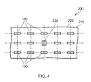
- a panel attachment system according to a second embodiment of the invention is designated generally by the reference numeral 200.
- Features of the panel attachment system 200 which correspond to those of panel attachment device 100 have been given corresponding reference numerals for ease of reference.
- the panel attachment system 200 has a panel 210 that is spaced apart from a casing 220.
- a single fixed mount 230 fixedly connects the panel 210 and the casing 220.
- a plurality of panel attachment devices 100 are then arranged across the surface of the casing 220, and the panel 210.
- the panel attachment devices 100 are arranged row-wise across the panel/casing surface with each of the links 130 arranged so that they each lie in the same plane or in parallel planes. This ensures that any lateral and longitudinal movement of the panel 210 relative to the casing 220 resulting from thermal growth of the panel 210 can readily be accommodated by relative movement between the first and second ends of the link 132,134 and respective ones of the first and second brackets 110,120.
Landscapes
- Engineering & Computer Science (AREA)
- General Engineering & Computer Science (AREA)
- Mechanical Engineering (AREA)
- Chemical & Material Sciences (AREA)
- Combustion & Propulsion (AREA)
- Pivots And Pivotal Connections (AREA)
- Exhaust Silencers (AREA)
- Connection Of Plates (AREA)
Abstract
Description
- The present invention relates to a panel attachment system and particularly, but not exclusively, to a panel attachment system for an exhaust gas duct.
- The exhaust duct for a gas turbine engine is conventionally a circular duct which connects to the turbine stage outlet of the engine. The use of a circular duct is convenient since it can be readily connected to the turbine outlet of the engine. In addition, thermal expansion of the exhaust duct resulting from the heat of the exhaust gas flow may be readily accommodated by the radial growth of the exhaust duct.
- However, in many gas turbine engine installations it is desirable for the exit portion of the exhaust duct to be non-circular because this can make the mechanical installation of the exhaust duct into its supporting structure easier and more convenient.
- In particular it is advantageous for the exhaust duct to be rectilinear in cross-section to facilitate the mounting of the exhaust duct within its surrounding structure.
- Due to the need to accommodate dimensional changes in the exhaust duct resulting from the hot exhaust gases passing through the exhaust duct it is known to provide a duct mounting arrangement that independently accommodates both axial and lateral growth of the exhaust duct resulting from thermal expansion of the duct. Such mounting arrangements are required to accommodate movement of the duct both axially and laterally and can be mechanically complicated.
- According to a first aspect of the present invention there is provided a panel attachment device for removably connecting a panel to a casing, the panel attachment device comprising:
- a first bracket;
- a second bracket; and
- a link having a first end and an opposite second end,
- The relative rotation between the first bracket and the second bracket enables the panel attachment device to maintain a desired predetermined spacing between panel and casing without transmitting bending loads into the link. This allows the link to be sized to withstand only axial loads thus enabling the weight of the attachment device to be reduced so making the device more efficient and attractive to a user.
- Optionally, the link is an elongate member.
- The link may be formed with a length to suit a particular panel to casing spacing by simply varying the distance between the first end and the second end.
- Optionally, each of the first end and second end comprises a spherical bearing, the outer diameter of each spherical bearing being fixedly connected to a corresponding one of the first and second ends, the inner diameter of each spherical bearing being fixedly connected to a corresponding one of the first and second brackets, the axis of each spherical bearing being coincident with one another.
- A spherical bearing allows for relative rotation between respective ones of the first and second brackets and corresponding first and second ends of the link both in the plane of the link (i.e. fore/aft) and across the plane of the link (i.e. side to side). This makes the attachment device more convenient and capable of handling a wide variety of small relative displacements between the first and second brackets and corresponding first and second ends of the link.
- Optionally, the link comprises a centre portion interposed between the first end and the second end, a lateral cross-sectional area of the centre portion being smaller than a lateral cross-sectional area of the first end and the second end.
- Optionally, each of the first bracket, second bracket and link is formed from a sheet metal or a sheet metal alloy.
- The use of sheet metal enables the first and second brackets and the link to be produced at low cost and because, as outlined above, these parts need only withstand axial loads they can be structurally efficient.
- Optionally, a cross-section of the centre portion is streamlined in a plane substantially normal to the axis of each of the spherical bearings.
- It is common practice for a cooling air flow to be circulated in the space between the panel and the casing. Since the link is positioned in this space it can reduce the flow efficiency of this cooling air flow. Consequently it is desirable to streamline the centre portion of the link so as to minimise any disruption to the cooling air flow passing over the link.
- According to a second aspect of the present invention there is provided a panel attachment system comprising:
- a panel;
- a casing;
- a centre mount; and
- a plurality of panel attachment devices as defined by the first embodiment of the invention,
- The use of a plurality of panel attachment assemblies enables a panel to be attached to a casing while accommodating any thermal growth of the panel and still maintaining the positional arrangement of the panel and casing.
- A single fixed mount is positioned so that the thermal growth of the panel occurs in directions that are predictable and optimum for the particular design.
- Other aspects of the invention provide devices, methods and systems which include and/or implement some or all of the actions described herein. The illustrative aspects of the invention are designed to solve one or more of the problems herein described and/or one or more other problems not discussed.
- There now follows a description of an embodiment of the invention, by way of nonlimiting example, with reference being made to the accompanying drawings in which:
-
Figure 1 shows a perspective view of a panel attachment device according to a first embodiment of the invention; -
Figure 2 shows an end view of the attachment device ofFigure 1 ; -
Figure 3 shows an elevational view of the attachment device ofFigure 1 ; and -
Figure 4 is a schematic plan view of panel attachment system according to a second embodiment of the invention. - It is noted that the drawings may not be to scale. The drawings are intended to depict only typical aspects of the invention, and therefore should not be considered as limiting the scope of the invention. In the drawings, like numbering represents like elements between the drawings.
- Referring to
Figures 1 to 3 , a panel attachment device according to a first embodiment of the invention is designated generally by thereference numeral 100. Thepanel attachment device 100 removably connects apanel 210 to acasing 220 of an exhaust system (not shown) for a gas turbine engine (not shown) - The
panel attachment device 100 comprises afirst bracket 110, asecond bracket 120 and alink 130. - The
first bracket 110 is fixedly connected to thepanel 210 while thesecond bracket 120 is fixedly connected to theopposing casing 220. In the present arrangement each of the first and second brackets 110,120 are formed from sheet metal pressings. In alternative arrangements, the first and second brackets 110,120 may be formed from a fibre reinforced material, such as a carbon fibre reinforced composite material. - The
link 130 is formed from sheet metal and comprises afirst end 132, asecond end 134 and acentre portion 136. Thelink 130 has a 'dog bone' profile with a cross-sectional area 137 of thecentre portion 136 being smaller than a cross-sectional area 133,135 of the first and second ends 132,134. - The
centre portion 136 is formed with a generally rectangular cross-sectional area. The width sides of the rectangular cross-section are streamlined in order to minimise the disruption they produce on an air flow (shown as 'A' inFigure 2 ) passing over thecentre portion 136. - Each of the
first end 132 andsecond end 134 has a hole therethrough to accommodate aspherical bearing 140. Anouter diameter 142 of thespherical bearing 140 is fixedly connected to thefirst end 132 and thesecond end 134 of thelink 130. Aninner diameter 144 of thespherical bearing 140 is fixedly connected to respective ones of the first and second brackets 110,120. - In this way, any relative movement between the
link 130 and each of the first and second brackets 110,120 can be readily accommodated by the spherical bearing 140 movement. - Referring to
Figure 4 , a panel attachment system according to a second embodiment of the invention is designated generally by thereference numeral 200. Features of thepanel attachment system 200 which correspond to those ofpanel attachment device 100 have been given corresponding reference numerals for ease of reference. - The
panel attachment system 200 has apanel 210 that is spaced apart from acasing 220. A singlefixed mount 230 fixedly connects thepanel 210 and thecasing 220. A plurality ofpanel attachment devices 100 are then arranged across the surface of thecasing 220, and thepanel 210. - The
panel attachment devices 100 are arranged row-wise across the panel/casing surface with each of thelinks 130 arranged so that they each lie in the same plane or in parallel planes. This ensures that any lateral and longitudinal movement of thepanel 210 relative to thecasing 220 resulting from thermal growth of thepanel 210 can readily be accommodated by relative movement between the first and second ends of the link 132,134 and respective ones of the first and second brackets 110,120. - The foregoing description of various aspects of the invention has been presented for purposes of illustration and description. It is not intended to be exhaustive or to limit the invention to the precise form disclosed, and obviously, many modifications and variations are possible. Such modifications and variations that may be apparent to a person of skill in the art are included within the scope of the invention as defined by the accompanying claims.
Claims (7)
- A panel attachment device (100) for removably connecting a panel (210) to a casing (220), the panel attachment device (100) comprising:a first bracket (110);a second bracket (120); anda link (130) having a first end (132) and an opposite second end (134),wherein the first end (132) is removably connected to the first bracket (110) and the second end (134) is removably connected to the second bracket (120), each of the first end (132) and second end (134) being located by, and rotatable relative to, the first bracket (110) and second bracket (120) respectively.
- The panel attachment device (100) as claimed in Claim 1, wherein the link (130) is an elongate member.
- The panel attachment device (100) as claimed in Claim 1, wherein each of the first end (132) and second end (134) comprises a spherical bearing (140), the outer diameter (142) of each spherical bearing (140) being fixedly connected to a corresponding one of the first and second ends(132;134), the inner diameter (144) of each spherical bearing (140) being fixedly connected to a corresponding one of the first and second brackets (110;120), the axis of each spherical bearing (140) being coincident with one another.
- The panel attachment device (100) as claimed in Claim 1, wherein the link (130) comprises a centre portion (136) interposed between the first end (132) and the second end (134), a lateral cross-sectional area of the centre portion (136) being smaller than a lateral cross-sectional area of the first end (132) and the second end (134).
- The panel attachment device (100) as claimed in Claim 1, wherein each of the first bracket (110), second bracket (120) and link (130) is formed from a sheet metal or a sheet metal alloy.
- The panel attachment device (100) as claimed in Claim 1, wherein a cross-section of the centre portion (136) is streamlined in a plane substantially normal to the axis of each of the spherical bearings.
- A panel attachment system (200) comprising:a panel (210);a casing (220);a centre mount (230); anda plurality of panel attachment devices (100) as claimed in any one of Claims 1 to 6, the centre mount (230) fixedly connecting the panel (210) and the casing (220), each of the first brackets (110) being fixedly connected to the panel (210), and each of the second brackets (120) being fixedly connected to the casing (220), such that each of the spherical bearing axes is parallel to each other.
Applications Claiming Priority (1)
| Application Number | Priority Date | Filing Date | Title |
|---|---|---|---|
| GBGB1314667.5A GB201314667D0 (en) | 2013-08-16 | 2013-08-16 | A panel attachment system |
Publications (2)
| Publication Number | Publication Date |
|---|---|
| EP2837776A1 true EP2837776A1 (en) | 2015-02-18 |
| EP2837776B1 EP2837776B1 (en) | 2016-09-14 |
Family
ID=49301794
Family Applications (1)
| Application Number | Title | Priority Date | Filing Date |
|---|---|---|---|
| EP14177939.7A Not-in-force EP2837776B1 (en) | 2013-08-16 | 2014-07-22 | A panel attachment system |
Country Status (3)
| Country | Link |
|---|---|
| US (1) | US9243654B2 (en) |
| EP (1) | EP2837776B1 (en) |
| GB (1) | GB201314667D0 (en) |
Cited By (1)
| Publication number | Priority date | Publication date | Assignee | Title |
|---|---|---|---|---|
| FR3097204A1 (en) * | 2019-06-17 | 2020-12-18 | Airbus Operations | ENGINE ATTACHMENT FOR AN AIRCRAFT ENGINE CONTAINING A CONNECTING ROD AND ANTI-TIPPING SYSTEM OF THE ROD |
Families Citing this family (1)
| Publication number | Priority date | Publication date | Assignee | Title |
|---|---|---|---|---|
| EP2679780B8 (en) * | 2012-06-28 | 2016-09-14 | General Electric Technology GmbH | Diffuser for the exhaust section of a gas turbine and gas turbine with such a diffuser |
Citations (5)
| Publication number | Priority date | Publication date | Assignee | Title |
|---|---|---|---|---|
| GB2141492A (en) * | 1983-06-13 | 1984-12-19 | United Technologies Corp | Nozzle flap edge seal |
| EP0741074A1 (en) * | 1995-05-03 | 1996-11-06 | The Boeing Company | Three link failsafe engine mount |
| US5689435A (en) * | 1995-12-20 | 1997-11-18 | General Electric Company | Systems and methods for automated bracket design |
| US20090077978A1 (en) * | 2007-09-24 | 2009-03-26 | United Technologies Corporation One Financial Plaza | Self-aligning liner support hanger |
| US20090293498A1 (en) * | 2008-06-02 | 2009-12-03 | Dale William Petty | Pivoting liner hanger |
Family Cites Families (26)
| Publication number | Priority date | Publication date | Assignee | Title |
|---|---|---|---|---|
| US3295764A (en) * | 1965-04-27 | 1967-01-03 | United Aircraft Corp | Variable area exhaust nozzle |
| FR2180440B1 (en) * | 1972-04-17 | 1976-06-11 | Snecma | |
| FR2288868A1 (en) | 1973-12-03 | 1976-05-21 | Snecma | TURBOREACTOR AND REACTOR EJECTION CHANNEL PROVIDED WITH SUCH A CHANNEL |
| US4571936A (en) * | 1985-07-10 | 1986-02-25 | The United States Of America As Represented By The Secretary Of The Air Force | Length adjustable strut link with low aerodynamic drag |
| ES2075782B1 (en) | 1992-02-20 | 1998-03-16 | Sener Ing & Sist | ADJUSTABLE VARIABLE GEOMETRY NOZZLE FOR GAS TURBINES. |
| US5277860A (en) * | 1992-09-03 | 1994-01-11 | Sinclair William S | Process for making an all-plastic rod end |
| US5277382A (en) * | 1992-10-13 | 1994-01-11 | General Electric Company | Aircraft engine forward mount |
| US5303880A (en) * | 1992-10-28 | 1994-04-19 | General Electric Company | Aircraft engine pin mount |
| US5351423A (en) * | 1993-01-15 | 1994-10-04 | Raynald Vohl | Ball and socket joint for snowblower chute control rod linkages |
| US5402605A (en) * | 1993-04-12 | 1995-04-04 | Paules; Eugene | Oscillating sander |
| US5460487A (en) * | 1994-11-09 | 1995-10-24 | United Technologies Corporation | Pitch adjustment assembly for bearingless main rotors |
| US5649417A (en) * | 1995-03-24 | 1997-07-22 | The Boeing Company | Fail-safe engine mount system |
| US5781989A (en) * | 1996-11-27 | 1998-07-21 | Eastlex Machine Corporation | Fastener attaching apparatus |
| US5782078A (en) * | 1996-12-17 | 1998-07-21 | General Electric Company | Tapered jam nut for turbine frame mount link |
| US6174210B1 (en) * | 1998-06-02 | 2001-01-16 | Bombardier Inc. | Watercraft control mechanism |
| US6170252B1 (en) * | 1998-12-14 | 2001-01-09 | United Technologies Corporation | Locator for a gearbox mount |
| US6212974B1 (en) * | 1998-12-17 | 2001-04-10 | United Technologies Corporation | Variable stiffness positioning link for a gearbox |
| US7584621B2 (en) | 2005-08-05 | 2009-09-08 | Siemens Energy, Inc. | Radially expanding turbine engine exhaust cylinder interface |
| DE07750434T1 (en) * | 2007-02-09 | 2010-01-28 | Bell Helicopter Textron, Inc., Fort Worth | SELF-STABLE THRUST-SAFETY CLAMP |
| CN101796265B (en) * | 2007-08-10 | 2013-01-16 | 杜克引擎有限公司 | Axial piston machines with rotation restraint mechanism |
| US8079607B2 (en) * | 2008-04-08 | 2011-12-20 | Roller Bearing Company Of America, Inc. | Spherical bearing for a steering joint |
| US8511098B2 (en) | 2008-06-12 | 2013-08-20 | United Technologies Corporation | Slideable liner link assembly |
| JP2011529163A (en) * | 2008-07-25 | 2011-12-01 | ケーブルクラフト モーション コントロールズ エルエルシー | High temperature bearing assembly and method of forming the same |
| US8667754B2 (en) * | 2008-08-26 | 2014-03-11 | The Boeing Company | Composite tie rod and method for making the same |
| AU2009238281B1 (en) * | 2009-11-16 | 2010-10-28 | CITS Engineering Pty Limited | Improvements in two-stroke engines |
| FR2975132B1 (en) | 2011-05-09 | 2015-06-26 | Snecma | SUSPENSION LINKS OF THE COLD FLOW CHANNEL OF A TURBOJUSTER WITH EXCENTRIC BALLS |
-
2013
- 2013-08-16 GB GBGB1314667.5A patent/GB201314667D0/en not_active Ceased
-
2014
- 2014-07-22 US US14/337,524 patent/US9243654B2/en active Active
- 2014-07-22 EP EP14177939.7A patent/EP2837776B1/en not_active Not-in-force
Patent Citations (5)
| Publication number | Priority date | Publication date | Assignee | Title |
|---|---|---|---|---|
| GB2141492A (en) * | 1983-06-13 | 1984-12-19 | United Technologies Corp | Nozzle flap edge seal |
| EP0741074A1 (en) * | 1995-05-03 | 1996-11-06 | The Boeing Company | Three link failsafe engine mount |
| US5689435A (en) * | 1995-12-20 | 1997-11-18 | General Electric Company | Systems and methods for automated bracket design |
| US20090077978A1 (en) * | 2007-09-24 | 2009-03-26 | United Technologies Corporation One Financial Plaza | Self-aligning liner support hanger |
| US20090293498A1 (en) * | 2008-06-02 | 2009-12-03 | Dale William Petty | Pivoting liner hanger |
Cited By (1)
| Publication number | Priority date | Publication date | Assignee | Title |
|---|---|---|---|---|
| FR3097204A1 (en) * | 2019-06-17 | 2020-12-18 | Airbus Operations | ENGINE ATTACHMENT FOR AN AIRCRAFT ENGINE CONTAINING A CONNECTING ROD AND ANTI-TIPPING SYSTEM OF THE ROD |
Also Published As
| Publication number | Publication date |
|---|---|
| US9243654B2 (en) | 2016-01-26 |
| EP2837776B1 (en) | 2016-09-14 |
| GB201314667D0 (en) | 2013-10-02 |
| US20150050072A1 (en) | 2015-02-19 |
Similar Documents
| Publication | Publication Date | Title |
|---|---|---|
| US7900872B2 (en) | Nacelle inlet thermal anti-icing spray duct support system | |
| CN104271892B (en) | Dual spring bearings housing | |
| US7594404B2 (en) | Embedded mount for mid-turbine frame | |
| EP2149681A2 (en) | Nested bearing cages | |
| US9146004B2 (en) | Cabin air compressor support bracket | |
| US20140263837A1 (en) | Nacelle inlet thermal anti-ice spray duct | |
| US11084599B2 (en) | Inlet screen for aircraft engines | |
| US9243654B2 (en) | Panel attachment system | |
| EP2796699B1 (en) | A panel attachment system and a method of using the same | |
| KR20080042760A (en) | Devices with turbomachines, coolers and carrying frames | |
| EP3187717A1 (en) | Tube thermal coupling assembly | |
| EP3708809A3 (en) | Heat exchanger suspension system with pipe-to linkage spring rate ratio | |
| US9599132B2 (en) | Anti-rotation lug for mounting components together | |
| US20150028166A1 (en) | Panel attachment system | |
| EP3531058B1 (en) | Heat exchanger assembly | |
| EP2837811A1 (en) | A panel attachment system | |
| EP2765295A2 (en) | A panel mounting arrangement | |
| EP3354578A1 (en) | Flexible joints assembly with flexure rods | |
| EP2946094A1 (en) | Heat shield for gas turbine engine gearbox | |
| US10927711B2 (en) | Tunable compliant attachment structure | |
| EP2647801A3 (en) | Bearing cooling system for flexible shaft turbomachine | |
| US20140175791A1 (en) | Single tool installation/removal of restraint cable with anti-rotation feature | |
| EP2933467A1 (en) | A panel connection system and a method of using the same |
Legal Events
| Date | Code | Title | Description |
|---|---|---|---|
| 17P | Request for examination filed |
Effective date: 20140722 |
|
| AK | Designated contracting states |
Kind code of ref document: A1 Designated state(s): AL AT BE BG CH CY CZ DE DK EE ES FI FR GB GR HR HU IE IS IT LI LT LU LV MC MK MT NL NO PL PT RO RS SE SI SK SM TR |
|
| AX | Request for extension of the european patent |
Extension state: BA ME |
|
| PUAI | Public reference made under article 153(3) epc to a published international application that has entered the european phase |
Free format text: ORIGINAL CODE: 0009012 |
|
| RAP1 | Party data changed (applicant data changed or rights of an application transferred) |
Owner name: ROLLS-ROYCE PLC |
|
| R17P | Request for examination filed (corrected) |
Effective date: 20150812 |
|
| RBV | Designated contracting states (corrected) |
Designated state(s): AL AT BE BG CH CY CZ DE DK EE ES FI FR GB GR HR HU IE IS IT LI LT LU LV MC MK MT NL NO PL PT RO RS SE SI SK SM TR |
|
| GRAP | Despatch of communication of intention to grant a patent |
Free format text: ORIGINAL CODE: EPIDOSNIGR1 |
|
| GRAS | Grant fee paid |
Free format text: ORIGINAL CODE: EPIDOSNIGR3 |
|
| INTG | Intention to grant announced |
Effective date: 20160616 |
|
| GRAA | (expected) grant |
Free format text: ORIGINAL CODE: 0009210 |
|
| AK | Designated contracting states |
Kind code of ref document: B1 Designated state(s): AL AT BE BG CH CY CZ DE DK EE ES FI FR GB GR HR HU IE IS IT LI LT LU LV MC MK MT NL NO PL PT RO RS SE SI SK SM TR |
|
| REG | Reference to a national code |
Ref country code: GB Ref legal event code: FG4D |
|
| REG | Reference to a national code |
Ref country code: CH Ref legal event code: EP |
|
| REG | Reference to a national code |
Ref country code: IE Ref legal event code: FG4D |
|
| REG | Reference to a national code |
Ref country code: AT Ref legal event code: REF Ref document number: 829243 Country of ref document: AT Kind code of ref document: T Effective date: 20161015 |
|
| REG | Reference to a national code |
Ref country code: DE Ref legal event code: R096 Ref document number: 602014003624 Country of ref document: DE |
|
| REG | Reference to a national code |
Ref country code: LT Ref legal event code: MG4D |
|
| REG | Reference to a national code |
Ref country code: NL Ref legal event code: MP Effective date: 20160914 |
|
| PG25 | Lapsed in a contracting state [announced via postgrant information from national office to epo] |
Ref country code: NO Free format text: LAPSE BECAUSE OF FAILURE TO SUBMIT A TRANSLATION OF THE DESCRIPTION OR TO PAY THE FEE WITHIN THE PRESCRIBED TIME-LIMIT Effective date: 20161214 Ref country code: RS Free format text: LAPSE BECAUSE OF FAILURE TO SUBMIT A TRANSLATION OF THE DESCRIPTION OR TO PAY THE FEE WITHIN THE PRESCRIBED TIME-LIMIT Effective date: 20160914 Ref country code: LT Free format text: LAPSE BECAUSE OF FAILURE TO SUBMIT A TRANSLATION OF THE DESCRIPTION OR TO PAY THE FEE WITHIN THE PRESCRIBED TIME-LIMIT Effective date: 20160914 Ref country code: FI Free format text: LAPSE BECAUSE OF FAILURE TO SUBMIT A TRANSLATION OF THE DESCRIPTION OR TO PAY THE FEE WITHIN THE PRESCRIBED TIME-LIMIT Effective date: 20160914 Ref country code: HR Free format text: LAPSE BECAUSE OF FAILURE TO SUBMIT A TRANSLATION OF THE DESCRIPTION OR TO PAY THE FEE WITHIN THE PRESCRIBED TIME-LIMIT Effective date: 20160914 |
|
| REG | Reference to a national code |
Ref country code: AT Ref legal event code: MK05 Ref document number: 829243 Country of ref document: AT Kind code of ref document: T Effective date: 20160914 |
|
| PG25 | Lapsed in a contracting state [announced via postgrant information from national office to epo] |
Ref country code: LV Free format text: LAPSE BECAUSE OF FAILURE TO SUBMIT A TRANSLATION OF THE DESCRIPTION OR TO PAY THE FEE WITHIN THE PRESCRIBED TIME-LIMIT Effective date: 20160914 Ref country code: NL Free format text: LAPSE BECAUSE OF FAILURE TO SUBMIT A TRANSLATION OF THE DESCRIPTION OR TO PAY THE FEE WITHIN THE PRESCRIBED TIME-LIMIT Effective date: 20160914 Ref country code: GR Free format text: LAPSE BECAUSE OF FAILURE TO SUBMIT A TRANSLATION OF THE DESCRIPTION OR TO PAY THE FEE WITHIN THE PRESCRIBED TIME-LIMIT Effective date: 20161215 Ref country code: SE Free format text: LAPSE BECAUSE OF FAILURE TO SUBMIT A TRANSLATION OF THE DESCRIPTION OR TO PAY THE FEE WITHIN THE PRESCRIBED TIME-LIMIT Effective date: 20160914 |
|
| PG25 | Lapsed in a contracting state [announced via postgrant information from national office to epo] |
Ref country code: RO Free format text: LAPSE BECAUSE OF FAILURE TO SUBMIT A TRANSLATION OF THE DESCRIPTION OR TO PAY THE FEE WITHIN THE PRESCRIBED TIME-LIMIT Effective date: 20160914 Ref country code: EE Free format text: LAPSE BECAUSE OF FAILURE TO SUBMIT A TRANSLATION OF THE DESCRIPTION OR TO PAY THE FEE WITHIN THE PRESCRIBED TIME-LIMIT Effective date: 20160914 |
|
| PG25 | Lapsed in a contracting state [announced via postgrant information from national office to epo] |
Ref country code: PL Free format text: LAPSE BECAUSE OF FAILURE TO SUBMIT A TRANSLATION OF THE DESCRIPTION OR TO PAY THE FEE WITHIN THE PRESCRIBED TIME-LIMIT Effective date: 20160914 Ref country code: ES Free format text: LAPSE BECAUSE OF FAILURE TO SUBMIT A TRANSLATION OF THE DESCRIPTION OR TO PAY THE FEE WITHIN THE PRESCRIBED TIME-LIMIT Effective date: 20160914 Ref country code: CZ Free format text: LAPSE BECAUSE OF FAILURE TO SUBMIT A TRANSLATION OF THE DESCRIPTION OR TO PAY THE FEE WITHIN THE PRESCRIBED TIME-LIMIT Effective date: 20160914 Ref country code: IS Free format text: LAPSE BECAUSE OF FAILURE TO SUBMIT A TRANSLATION OF THE DESCRIPTION OR TO PAY THE FEE WITHIN THE PRESCRIBED TIME-LIMIT Effective date: 20170114 Ref country code: BG Free format text: LAPSE BECAUSE OF FAILURE TO SUBMIT A TRANSLATION OF THE DESCRIPTION OR TO PAY THE FEE WITHIN THE PRESCRIBED TIME-LIMIT Effective date: 20161214 Ref country code: SK Free format text: LAPSE BECAUSE OF FAILURE TO SUBMIT A TRANSLATION OF THE DESCRIPTION OR TO PAY THE FEE WITHIN THE PRESCRIBED TIME-LIMIT Effective date: 20160914 Ref country code: SM Free format text: LAPSE BECAUSE OF FAILURE TO SUBMIT A TRANSLATION OF THE DESCRIPTION OR TO PAY THE FEE WITHIN THE PRESCRIBED TIME-LIMIT Effective date: 20160914 Ref country code: BE Free format text: LAPSE BECAUSE OF FAILURE TO SUBMIT A TRANSLATION OF THE DESCRIPTION OR TO PAY THE FEE WITHIN THE PRESCRIBED TIME-LIMIT Effective date: 20160914 Ref country code: PT Free format text: LAPSE BECAUSE OF FAILURE TO SUBMIT A TRANSLATION OF THE DESCRIPTION OR TO PAY THE FEE WITHIN THE PRESCRIBED TIME-LIMIT Effective date: 20170116 Ref country code: AT Free format text: LAPSE BECAUSE OF FAILURE TO SUBMIT A TRANSLATION OF THE DESCRIPTION OR TO PAY THE FEE WITHIN THE PRESCRIBED TIME-LIMIT Effective date: 20160914 |
|
| REG | Reference to a national code |
Ref country code: DE Ref legal event code: R097 Ref document number: 602014003624 Country of ref document: DE |
|
| PG25 | Lapsed in a contracting state [announced via postgrant information from national office to epo] |
Ref country code: IT Free format text: LAPSE BECAUSE OF FAILURE TO SUBMIT A TRANSLATION OF THE DESCRIPTION OR TO PAY THE FEE WITHIN THE PRESCRIBED TIME-LIMIT Effective date: 20160914 |
|
| PLBE | No opposition filed within time limit |
Free format text: ORIGINAL CODE: 0009261 |
|
| STAA | Information on the status of an ep patent application or granted ep patent |
Free format text: STATUS: NO OPPOSITION FILED WITHIN TIME LIMIT |
|
| REG | Reference to a national code |
Ref country code: FR Ref legal event code: PLFP Year of fee payment: 4 |
|
| PG25 | Lapsed in a contracting state [announced via postgrant information from national office to epo] |
Ref country code: DK Free format text: LAPSE BECAUSE OF FAILURE TO SUBMIT A TRANSLATION OF THE DESCRIPTION OR TO PAY THE FEE WITHIN THE PRESCRIBED TIME-LIMIT Effective date: 20160914 |
|
| 26N | No opposition filed |
Effective date: 20170615 |
|
| PG25 | Lapsed in a contracting state [announced via postgrant information from national office to epo] |
Ref country code: SI Free format text: LAPSE BECAUSE OF FAILURE TO SUBMIT A TRANSLATION OF THE DESCRIPTION OR TO PAY THE FEE WITHIN THE PRESCRIBED TIME-LIMIT Effective date: 20160914 |
|
| REG | Reference to a national code |
Ref country code: CH Ref legal event code: PL |
|
| REG | Reference to a national code |
Ref country code: IE Ref legal event code: MM4A |
|
| PG25 | Lapsed in a contracting state [announced via postgrant information from national office to epo] |
Ref country code: IE Free format text: LAPSE BECAUSE OF NON-PAYMENT OF DUE FEES Effective date: 20170722 Ref country code: LI Free format text: LAPSE BECAUSE OF NON-PAYMENT OF DUE FEES Effective date: 20170731 Ref country code: CH Free format text: LAPSE BECAUSE OF NON-PAYMENT OF DUE FEES Effective date: 20170731 |
|
| PG25 | Lapsed in a contracting state [announced via postgrant information from national office to epo] |
Ref country code: LU Free format text: LAPSE BECAUSE OF NON-PAYMENT OF DUE FEES Effective date: 20170722 |
|
| REG | Reference to a national code |
Ref country code: FR Ref legal event code: PLFP Year of fee payment: 5 |
|
| PG25 | Lapsed in a contracting state [announced via postgrant information from national office to epo] |
Ref country code: MT Free format text: LAPSE BECAUSE OF NON-PAYMENT OF DUE FEES Effective date: 20170722 |
|
| PG25 | Lapsed in a contracting state [announced via postgrant information from national office to epo] |
Ref country code: AL Free format text: LAPSE BECAUSE OF FAILURE TO SUBMIT A TRANSLATION OF THE DESCRIPTION OR TO PAY THE FEE WITHIN THE PRESCRIBED TIME-LIMIT Effective date: 20160914 |
|
| PG25 | Lapsed in a contracting state [announced via postgrant information from national office to epo] |
Ref country code: HU Free format text: LAPSE BECAUSE OF FAILURE TO SUBMIT A TRANSLATION OF THE DESCRIPTION OR TO PAY THE FEE WITHIN THE PRESCRIBED TIME-LIMIT; INVALID AB INITIO Effective date: 20140722 Ref country code: MC Free format text: LAPSE BECAUSE OF FAILURE TO SUBMIT A TRANSLATION OF THE DESCRIPTION OR TO PAY THE FEE WITHIN THE PRESCRIBED TIME-LIMIT Effective date: 20160914 |
|
| PG25 | Lapsed in a contracting state [announced via postgrant information from national office to epo] |
Ref country code: CY Free format text: LAPSE BECAUSE OF FAILURE TO SUBMIT A TRANSLATION OF THE DESCRIPTION OR TO PAY THE FEE WITHIN THE PRESCRIBED TIME-LIMIT Effective date: 20160914 |
|
| PG25 | Lapsed in a contracting state [announced via postgrant information from national office to epo] |
Ref country code: MK Free format text: LAPSE BECAUSE OF FAILURE TO SUBMIT A TRANSLATION OF THE DESCRIPTION OR TO PAY THE FEE WITHIN THE PRESCRIBED TIME-LIMIT Effective date: 20160914 |
|
| PG25 | Lapsed in a contracting state [announced via postgrant information from national office to epo] |
Ref country code: TR Free format text: LAPSE BECAUSE OF FAILURE TO SUBMIT A TRANSLATION OF THE DESCRIPTION OR TO PAY THE FEE WITHIN THE PRESCRIBED TIME-LIMIT Effective date: 20160914 |
|
| PGFP | Annual fee paid to national office [announced via postgrant information from national office to epo] |
Ref country code: DE Payment date: 20200928 Year of fee payment: 7 Ref country code: GB Payment date: 20200724 Year of fee payment: 7 Ref country code: FR Payment date: 20200728 Year of fee payment: 7 |
|
| REG | Reference to a national code |
Ref country code: DE Ref legal event code: R119 Ref document number: 602014003624 Country of ref document: DE |
|
| GBPC | Gb: european patent ceased through non-payment of renewal fee |
Effective date: 20210722 |
|
| PG25 | Lapsed in a contracting state [announced via postgrant information from national office to epo] |
Ref country code: GB Free format text: LAPSE BECAUSE OF NON-PAYMENT OF DUE FEES Effective date: 20210722 Ref country code: DE Free format text: LAPSE BECAUSE OF NON-PAYMENT OF DUE FEES Effective date: 20220201 |
|
| PG25 | Lapsed in a contracting state [announced via postgrant information from national office to epo] |
Ref country code: FR Free format text: LAPSE BECAUSE OF NON-PAYMENT OF DUE FEES Effective date: 20210731 |