EP2837734A1 - Air conditioner - Google Patents
Air conditioner Download PDFInfo
- Publication number
- EP2837734A1 EP2837734A1 EP13767408.1A EP13767408A EP2837734A1 EP 2837734 A1 EP2837734 A1 EP 2837734A1 EP 13767408 A EP13767408 A EP 13767408A EP 2837734 A1 EP2837734 A1 EP 2837734A1
- Authority
- EP
- European Patent Office
- Prior art keywords
- air
- humidity
- air blowing
- dehumidifying
- temperature
- Prior art date
- Legal status (The legal status is an assumption and is not a legal conclusion. Google has not performed a legal analysis and makes no representation as to the accuracy of the status listed.)
- Withdrawn
Links
Images



Classifications
-
- F—MECHANICAL ENGINEERING; LIGHTING; HEATING; WEAPONS; BLASTING
- F24—HEATING; RANGES; VENTILATING
- F24F—AIR-CONDITIONING; AIR-HUMIDIFICATION; VENTILATION; USE OF AIR CURRENTS FOR SCREENING
- F24F3/00—Air-conditioning systems in which conditioned primary air is supplied from one or more central stations to distributing units in the rooms or spaces where it may receive secondary treatment; Apparatus specially designed for such systems
- F24F3/12—Air-conditioning systems in which conditioned primary air is supplied from one or more central stations to distributing units in the rooms or spaces where it may receive secondary treatment; Apparatus specially designed for such systems characterised by the treatment of the air otherwise than by heating and cooling
- F24F3/14—Air-conditioning systems in which conditioned primary air is supplied from one or more central stations to distributing units in the rooms or spaces where it may receive secondary treatment; Apparatus specially designed for such systems characterised by the treatment of the air otherwise than by heating and cooling by humidification; by dehumidification
-
- D—TEXTILES; PAPER
- D06—TREATMENT OF TEXTILES OR THE LIKE; LAUNDERING; FLEXIBLE MATERIALS NOT OTHERWISE PROVIDED FOR
- D06F—LAUNDERING, DRYING, IRONING, PRESSING OR FOLDING TEXTILE ARTICLES
- D06F58/00—Domestic laundry dryers
-
- F—MECHANICAL ENGINEERING; LIGHTING; HEATING; WEAPONS; BLASTING
- F24—HEATING; RANGES; VENTILATING
- F24F—AIR-CONDITIONING; AIR-HUMIDIFICATION; VENTILATION; USE OF AIR CURRENTS FOR SCREENING
- F24F11/00—Control or safety arrangements
- F24F11/30—Control or safety arrangements for purposes related to the operation of the system, e.g. for safety or monitoring
-
- F—MECHANICAL ENGINEERING; LIGHTING; HEATING; WEAPONS; BLASTING
- F24—HEATING; RANGES; VENTILATING
- F24F—AIR-CONDITIONING; AIR-HUMIDIFICATION; VENTILATION; USE OF AIR CURRENTS FOR SCREENING
- F24F11/00—Control or safety arrangements
- F24F11/30—Control or safety arrangements for purposes related to the operation of the system, e.g. for safety or monitoring
- F24F11/49—Control or safety arrangements for purposes related to the operation of the system, e.g. for safety or monitoring ensuring correct operation, e.g. by trial operation or configuration checks
-
- F—MECHANICAL ENGINEERING; LIGHTING; HEATING; WEAPONS; BLASTING
- F24—HEATING; RANGES; VENTILATING
- F24F—AIR-CONDITIONING; AIR-HUMIDIFICATION; VENTILATION; USE OF AIR CURRENTS FOR SCREENING
- F24F11/00—Control or safety arrangements
- F24F11/70—Control systems characterised by their outputs; Constructional details thereof
- F24F11/72—Control systems characterised by their outputs; Constructional details thereof for controlling the supply of treated air, e.g. its pressure
- F24F11/74—Control systems characterised by their outputs; Constructional details thereof for controlling the supply of treated air, e.g. its pressure for controlling air flow rate or air velocity
-
- F—MECHANICAL ENGINEERING; LIGHTING; HEATING; WEAPONS; BLASTING
- F24—HEATING; RANGES; VENTILATING
- F24F—AIR-CONDITIONING; AIR-HUMIDIFICATION; VENTILATION; USE OF AIR CURRENTS FOR SCREENING
- F24F11/00—Control or safety arrangements
- F24F11/89—Arrangement or mounting of control or safety devices
-
- F—MECHANICAL ENGINEERING; LIGHTING; HEATING; WEAPONS; BLASTING
- F26—DRYING
- F26B—DRYING SOLID MATERIALS OR OBJECTS BY REMOVING LIQUID THEREFROM
- F26B9/00—Machines or apparatus for drying solid materials or objects at rest or with only local agitation; Domestic airing cupboards
- F26B9/06—Machines or apparatus for drying solid materials or objects at rest or with only local agitation; Domestic airing cupboards in stationary drums or chambers
-
- D—TEXTILES; PAPER
- D06—TREATMENT OF TEXTILES OR THE LIKE; LAUNDERING; FLEXIBLE MATERIALS NOT OTHERWISE PROVIDED FOR
- D06F—LAUNDERING, DRYING, IRONING, PRESSING OR FOLDING TEXTILE ARTICLES
- D06F2103/00—Parameters monitored or detected for the control of domestic laundry washing machines, washer-dryers or laundry dryers
-
- D—TEXTILES; PAPER
- D06—TREATMENT OF TEXTILES OR THE LIKE; LAUNDERING; FLEXIBLE MATERIALS NOT OTHERWISE PROVIDED FOR
- D06F—LAUNDERING, DRYING, IRONING, PRESSING OR FOLDING TEXTILE ARTICLES
- D06F2103/00—Parameters monitored or detected for the control of domestic laundry washing machines, washer-dryers or laundry dryers
- D06F2103/02—Characteristics of laundry or load
- D06F2103/08—Humidity
-
- D—TEXTILES; PAPER
- D06—TREATMENT OF TEXTILES OR THE LIKE; LAUNDERING; FLEXIBLE MATERIALS NOT OTHERWISE PROVIDED FOR
- D06F—LAUNDERING, DRYING, IRONING, PRESSING OR FOLDING TEXTILE ARTICLES
- D06F2103/00—Parameters monitored or detected for the control of domestic laundry washing machines, washer-dryers or laundry dryers
- D06F2103/02—Characteristics of laundry or load
- D06F2103/12—Temperature
-
- D—TEXTILES; PAPER
- D06—TREATMENT OF TEXTILES OR THE LIKE; LAUNDERING; FLEXIBLE MATERIALS NOT OTHERWISE PROVIDED FOR
- D06F—LAUNDERING, DRYING, IRONING, PRESSING OR FOLDING TEXTILE ARTICLES
- D06F2103/00—Parameters monitored or detected for the control of domestic laundry washing machines, washer-dryers or laundry dryers
- D06F2103/28—Air properties
- D06F2103/32—Temperature
-
- D—TEXTILES; PAPER
- D06—TREATMENT OF TEXTILES OR THE LIKE; LAUNDERING; FLEXIBLE MATERIALS NOT OTHERWISE PROVIDED FOR
- D06F—LAUNDERING, DRYING, IRONING, PRESSING OR FOLDING TEXTILE ARTICLES
- D06F2103/00—Parameters monitored or detected for the control of domestic laundry washing machines, washer-dryers or laundry dryers
- D06F2103/28—Air properties
- D06F2103/34—Humidity
-
- D—TEXTILES; PAPER
- D06—TREATMENT OF TEXTILES OR THE LIKE; LAUNDERING; FLEXIBLE MATERIALS NOT OTHERWISE PROVIDED FOR
- D06F—LAUNDERING, DRYING, IRONING, PRESSING OR FOLDING TEXTILE ARTICLES
- D06F2103/00—Parameters monitored or detected for the control of domestic laundry washing machines, washer-dryers or laundry dryers
- D06F2103/28—Air properties
- D06F2103/36—Flow or velocity
-
- D—TEXTILES; PAPER
- D06—TREATMENT OF TEXTILES OR THE LIKE; LAUNDERING; FLEXIBLE MATERIALS NOT OTHERWISE PROVIDED FOR
- D06F—LAUNDERING, DRYING, IRONING, PRESSING OR FOLDING TEXTILE ARTICLES
- D06F2103/00—Parameters monitored or detected for the control of domestic laundry washing machines, washer-dryers or laundry dryers
- D06F2103/64—Radiation, e.g. microwaves
-
- D—TEXTILES; PAPER
- D06—TREATMENT OF TEXTILES OR THE LIKE; LAUNDERING; FLEXIBLE MATERIALS NOT OTHERWISE PROVIDED FOR
- D06F—LAUNDERING, DRYING, IRONING, PRESSING OR FOLDING TEXTILE ARTICLES
- D06F2105/00—Systems or parameters controlled or affected by the control systems of washing machines, washer-dryers or laundry dryers
- D06F2105/16—Air properties
- D06F2105/24—Flow or velocity
-
- D—TEXTILES; PAPER
- D06—TREATMENT OF TEXTILES OR THE LIKE; LAUNDERING; FLEXIBLE MATERIALS NOT OTHERWISE PROVIDED FOR
- D06F—LAUNDERING, DRYING, IRONING, PRESSING OR FOLDING TEXTILE ARTICLES
- D06F2105/00—Systems or parameters controlled or affected by the control systems of washing machines, washer-dryers or laundry dryers
- D06F2105/30—Blowers
-
- D—TEXTILES; PAPER
- D06—TREATMENT OF TEXTILES OR THE LIKE; LAUNDERING; FLEXIBLE MATERIALS NOT OTHERWISE PROVIDED FOR
- D06F—LAUNDERING, DRYING, IRONING, PRESSING OR FOLDING TEXTILE ARTICLES
- D06F58/00—Domestic laundry dryers
- D06F58/32—Control of operations performed in domestic laundry dryers
- D06F58/34—Control of operations performed in domestic laundry dryers characterised by the purpose or target of the control
- D06F58/36—Control of operational steps, e.g. for optimisation or improvement of operational steps depending on the condition of the laundry
- D06F58/38—Control of operational steps, e.g. for optimisation or improvement of operational steps depending on the condition of the laundry of drying, e.g. to achieve the target humidity
-
- F—MECHANICAL ENGINEERING; LIGHTING; HEATING; WEAPONS; BLASTING
- F24—HEATING; RANGES; VENTILATING
- F24F—AIR-CONDITIONING; AIR-HUMIDIFICATION; VENTILATION; USE OF AIR CURRENTS FOR SCREENING
- F24F2110/00—Control inputs relating to air properties
- F24F2110/20—Humidity
Definitions
- the present invention relates to an air conditioner for dehumidifying the interior of a room and, more particularly, to an air conditioner having a function of drying the wash, that is, objects to be dried, that are dried in the room.
- Some conventional air conditioners are configured so as to recognize the decrease in sensible heat caused by the evaporation of water sucked up by objects to be dried by means of comparison using a controlling means between the detection result of temperature detected by an infrared detection means and the detection result of indoor atmosphere temperature detected by a temperature detecting means, and to determine the existence of the distribution of temperature lower than the indoor temperature caused by the decrease in sensible heat of the objects to be dried to be the arrangement range of the objects to be dried (for example, refer to Patent Literature 1).
- Patent Literature 1 Japanese Patent Laid-Open No. 2007-240100 (pages 2 to 4, Figures 3 to 5 )
- the above-described conventional air conditioner has a problem that, since a dehumidifying operation is controlled based on the detected temperature, even in an environment in which the humidity is low and the objects to be dried is easily dried, the same dehumidifying action is performed, so that electric power is consumed than necessary by the performing of unnecessary dehumidifying operation.
- the conventional air conditioner has a problem that electric power is consumed than necessary by the air blow of an excessive air blowing amount unsuitable for the situation.
- the present invention has been made to solve the above-described problems, and accordingly an object thereof is to provide an air conditioner that provides energy saving performance enhanced by the operation control carried out so that the number of rotations of the blower fan is changed so as to be suitable for the environmental conditions.
- An air conditioner of the present invention includes a dehumidifying means for removing water contained in air; an air blowing means, consisting of a motor and a blower fan, that sucks air in a room and blows out dried air, which is obtained by causing sucked air to pass through the dehumidifying means, into an interior of a room; a humidity detecting means for detecting a humidity of indoor air; a temperature detecting means for detecting a temperature of indoor air; a surface temperature detecting means for detecting a surface temperature in a room within a predetermined range; and a controlling means for controlling an air blowing amount of the air blowing means and the temperature detecting means, wherein the controlling means performs air blowing operation for operating the air blowing means for predetermined time, detects, from a surface temperature detected by the surface temperature detecting means and within the predetermined range, that objects to be dried such as wet clothing are arranged, and changes a number of rotations of the blower fan during operation of the air blowing means according to
- the present invention since the number of rotations of a blower fan is changed during the operation of an air blowing means according to the detection results of temperature and humidity, dehumidification and air blowing suitable for the drying of objects to be dried can be accomplished, and unnecessary electric power consumption can be reduced without impairing the drying performance of objects to be dried.
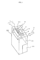
- Figure 1 is an appearance perspective view showing an air conditioner in accordance with a first embodiment of the present invention
- Figure 2 is a top plan view of a displaying means and an operating part of the air conditioner in accordance with the first embodiment of the present invention, which is viewed from the upside
- Figure 3 is a schematic configuration view showing the interior of the air conditioner in accordance with the first embodiment of the present invention
- Figure 4 is a schematic perspective view enlargedly showing a wind direction changing means shown in Figure 1
- Figure 5 is a conceptual view showing the detection range of an infrared sensor of the air conditioner in accordance with the first embodiment of the present invention.
- the air conditioner in accordance with the first embodiment of the present invention is configured by an air conditioner housing 100 configured so as to be self-standable, a suction port 101 for taking indoor air A into the air conditioner housing 100, a water storage tank 102 for storing water that is removed from the air taken into the suction port 101, and an exhaust port 103 for discharging dried air B, from which water has been removed, from the air conditioner housing 100 into the interior of a room.
- the exhaust port 103 is provided with a wind direction changeable means 1 that can change the wind direction of the dried air B, and the wind direction changeable means 1 is configured by a longitudinal louver 1a for changing the direction of wind in the vertical direction and a transverse louvers 1b for changing the direction of wind in the horizontal direction.
- the water storage tank 102 is detachably mounted to the air conditioner housing 100.
- an operating part 8 on the top surface of the air conditioner housing 100, there are provided an operating part 8 and a displaying means 12 for displaying various pieces of information on operation status, temperature, humidity, and the like.
- the operating part 8 is provided with, for example, a power switch 9, a dehumidification mode switch 10, and a drying mode switch 11.
- the above-described air conditioner includes a blower fan 2 constituting an air blowing means for generating a series of air flows that suck the indoor air A through the suction port 101 and discharge the dried air B through the exhaust port 103, a fan motor 2a for rotating the blower fan 2, a temperature sensor 3 (temperature detecting means) for detecting the temperature of the indoor air A sucked through the suction port 101, a humidity sensor 4 (humidity detecting means) for detecting the humidity of the indoor air A, and a dehumidifying means 5 for removing water contained in the indoor air A and generating the dried air B.
- a blower fan 2 constituting an air blowing means for generating a series of air flows that suck the indoor air A through the suction port 101 and discharge the dried air B through the exhaust port 103
- a fan motor 2a for rotating the blower fan 2
- a temperature sensor 3 temperature detecting means
- a humidity sensor 4 humidity detecting means
- a dehumidifying means 5 for
- the above-described air conditioner includes a longitudinally turnable motor 1c for turning the longitudinal louver 1a constituting the wind direction changeable means 1 in the vertical direction, a transversely turnable motor 1d for turning the transverse louvers 1b constituting the wind direction changeable means 1 in the horizontal direction, an infrared sensor 6 that is a surface temperature detecting means, and a control circuit 7 that incorporates a controlling means for controlling the wind direction changeable means 1, and controls the infrared sensor 6, which is a surface temperature detecting means, and the like.
- the various sensors such as the temperature sensor 3, the humidity sensor 4, and the infrared sensor 6 are configured so as to be controlled by the control circuit 7 and to detect various kinds of data, and furthermore, based on the detection results, the control circuit 7 controls the drive of the dehumidifying means 5, the fan motor 2a, the displaying means 12, and the like.
- the dehumidifying means 5 has only to be a means capable of removing and condensing water in the air.
- a system that forms a heat pump circuit and condenses water in the air in an evaporator there are used a desiccant system that condenses water in the air, which has been removed by a adsorbent, by using a heat exchanger, and the like system.
- the water removed from the indoor air A by the dehumidifying means 5 is stored in the water storage tank 102 as condensed water C.
- the longitudinal louver 1 a has a rectangular opening extending in the width direction of the air conditioner housing 100, and is configured so as to be turnable in the vertical direction substantially with the rotating shaft of the longitudinally turnable motor 1c being the axis.
- the transverse louvers 1b are arranged at equal intervals in the longitudinal louver 1a, are pivotally supported on the far portion on the side opposite to the opening of the longitudinal louver 1 a, and are configured so as to interlock with the drive of the transversely turnable motor 1 d.
- the infrared sensor 6 is mounted onto one surface of the transverse louver 1b arranged approximately in the center of the longitudinal louver 1a. Thereby, the detection range of surface temperature detected by the infrared sensor 6 is made approximately equal to the direction of the dried air B which direction is changed by the wind direction changeable means 1.
- the infrared sensor 6 can detect the surface temperature of objects lying in the whole region within the range in which the wind direction changeable means 1 can blow air, for example, clothing and towels that are wet after washing (hereinafter, referred generally to as "objects to be dried").
- the infrared sensor 6 an infrared sensor utilizing, for example, a thermoelectromotive force effect is used.
- the infrared sensor 6 is configured by an infrared ray absorbing membrane 6a that receives heat radiation (infrared rays) generated from the surface in a predetermined region, and a thermistor 6b for detecting the temperature of the infrared ray absorbing membrane 6a (refer to Figures 3 and 4 ).
- This infrared sensor 6 converts the difference between the temperature (hot contact) of a thermosensible portion of the infrared ray absorbing membrane 6a that is raised by the absorption of heat radiation and the temperature (cold contact) of the infrared ray absorbing membrane 6a detected by the thermistor 6b into an electric signal such as voltage, and sends the electric signal to the control circuit 7. From the magnitude of this electric signal, the surface temperature in the predetermined region can be detected.
- the whole scanning range 200 is a planar range spreading in the transverse direction (horizontal direction) and the longitudinal direction (vertical direction).
- the infrared sensor 6 is controlled so as to detect the surface temperature in the whole scanning range 200 for each area divided into plural numbers in both of the horizontal direction and the vertical direction (for example, 201 denotes an area of one section). Thereby, a detailed temperature map for a wide-range region can be prepared.
- the action of the control circuit 7 is started by the input of the power switch 9 shown in Figure 2 .
- the selection of dehumidification mode is detected by the operation of the dehumidification switch 10 provided in the operating part 8, air can be blown through the exhaust port 103 by driving the wind direction changeable means 1 so that the indoor humidity is the optimum humidity, the blower fan 2 is rotated by driving the fan motor 2a, and the dehumidifying means 5 is driven.
- control circuit 7 drives the longitudinally turnable motor 1c and the transversely turnable motor 1d of the wind direction changeable means 1 so that air is blown in the direction of the desired region of the interior of the room.
- the indoor air A is taken into the air conditioner housing 100 through the suction port 101, and after the temperature and humidity of the interior of the room have been detected by the temperature sensor 3 and the humidity sensor 4, respectively, the indoor air A is turned to the dried air B by the dehumidification accomplished by the dehumidifying means 5, and the dried air B is blown out into the interior of the room through the exhaust port 103.
- control circuit 7 is started by the input of the power switch 9 shown in Figure 2 .
- the selection of standard drying mode from the drying modes of objects to be dried represented by the wash such as clothing is detected by the operation of the drying mode switch 11 provided in the operating part 8, air can be blown through the exhaust port 103 by driving the wind direction changeable means 1, the blower fan 2 is rotated by driving the fan motor 2a, and the dehumidifying means 5 is driven.
- control circuit 7 reads the humidity of the interior of the room via the humidity sensor 4 from the indoor air A taken into the air conditioner housing 100, and determines whether or not the read humidity is higher than a preset humidity.
- the preset humidity is numerical value data that is preset corresponding to the indoor temperature detected by the temperature sensor 3, and the configuration is made such that the preset humidity is stored as the numerical value data in the a storing means, not shown, incorporated in the control circuit 7, and is read out into the control circuit 7 as necessary.
- the fan motor 2a and the wind direction changeable means 1 are controlled so that the dehumidifying capability of the dehumidifying means 5 is at the maximum until the indoor humidity decreases to a value not higher than the predetermined humidity.
- the control circuit 7 detects the surface temperature of each area (201) divided into plural numbers by using the infrared sensor 6, identifies the range in which the objects to be dried are arranged from the detection result of surface temperature, controls the longitudinally turnable motor 1c and the transversely turnable motor 1d so that the dried air B hits the identified range, and turns the louvers 1a and 1b to the direction of the objects to be dried.
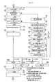
- Figure 6 is a part of a flowchart showing the action in the energy-saving drying mode of the air conditioner in accordance with the first embodiment of the present invention, showing Step 0 to Step 18 and Step 71
- Figure 7 is a part of the flowchart showing the action in the energy-saving drying mode of the air conditioner in accordance with the first embodiment of the present invention, showing Step 19 to Step 38
- Figure 8 is a part of the flowchart showing the action in the energy-saving drying mode of the air conditioner in accordance with the first embodiment of the present invention, showing Step 39 to Step 70
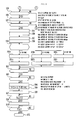
- Figure 9 is a part of the flowchart showing the action in the energy-saving drying mode of the air conditioner in accordance with the first embodiment of the present invention, showing Step 42 to Step 54.
- the dehumidifying means 5 In the standard drying mode, the dehumidifying means 5 is operated from the beginning of operation start, whereas, in the energy-saving drying mode, the dehumidifying means 5 is not operated at the beginning of operation start, and the fan motor 2a, which is an air blowing means, is operated to rotate the blower fan 2, whereby only the air blowing operation is performed.
- the fan motor 2a which is an air blowing means
- the representation of energy-saving drying mode has been used; however, the representation is not limited to this one, and any representation expressing the reduction in electric power consumption may be used.
- the term of electricity-saving mode or power-saving mode may be used.
- the action of the control circuit 7 is started by the input of the power switch 9.
- the drying mode switch 11 provided in the operating part 8
- the measurement of total operation time T from the operation start is started (S0
- the wind direction changeable means 1 is driven to enable air blowing through the exhaust port 103
- the air blowing operation is started by driving the fan motor 2a to rotate the blower fan 2 (S1).
- the operation of the dehumidifying means 5 is not started.
- the longitudinally turnable motor 1c and the transversely turnable motor 1d are controlled to enable the louvers 1a and 1b to be turned to regulate the air blowing directions (S2).
- the control circuit 7 operates the infrared sensor 6.
- the detection range (the whole scanning range 200) of surface temperature detected by the infrared sensor 6 is approximately equal to the direction of the dried air B that is changed by the longitudinal louver 1a and the transverse louvers 1b, so that the surface temperature of the whole region within the range in which the louvers 1a and 1b can blow air can be detected. Therefore, the surface temperature in the whole scanning range 200 of the infrared sensor 6 is detected for each area divided into plural numbers (for example, 201 denotes an area of one section) (S3 and S4).
- the surface temperature thereof becomes lower than the surrounding temperature.
- the infrared sensor 6 By detecting the range of the lowered temperature by using the infrared sensor 6, it is detected that the objects to be dried are arranged in this range.
- the early-stage degree of drying of objects to be dried is displayed on the displaying means 12 as an object-to-be-dried display mark 12a (S5), and the early-stage level of energy saving is displayed on the displaying means 12 as an energy saving level display mark 12b (S6).
- the shapes of the object-to-be-dried display mark 12a and the energy saving level display mark 12b are not limited to those shown in Figure 2 .
- Each shape may be a shape such that it can be seen that the mark shows the objects to be dried and a shape such that it can be seen that the mark shows the level of energy saving, respectively.
- the object-to-be-dried display mark 12a may be configured so that the display is changed according to the progress of drying, and in the case where the level of energy saving changes during the process, the energy saving level display mark 12b is configured so that the display is changed according to the change in the level of energy saving.
- the control circuit 7 shifts to an action for determining the number of rotations of the blower fan 2 (S7), the number of divided areas, in which the objects to be dried are arranged, is counted (S8), and the amounts of the objects to be dried are calculated (S9). It can be determined that if the number of counted areas is large, the amounts of the objects to be dried are large, and if the number of counted areas is small, the amounts of the objects to be dried are small.
- the process does not shift to the early-stage humidity determination until preset time has elapsed (S11 and S12) so that the temperature and humidity can be detected steadily.
- the indoor air A is taken into the air conditioner housing 100 through the suction port 101 by the rotation of the blower fan 2, and, at this time, the control circuit 7 reads indoor temperature RT detected by the temperature sensor 3, and reads the indoor humidity RH1 detected by the humidity sensor 4 (S14).
- the control circuit 7 compares the detected temperature RT of the indoor air A with a preset temperature (S 15).
- the preset temperature is set, for example, at 15°C, and if RT is lower than 15°C in S15, the process proceeds to S71, where the dehumidifying operation is started. If RT is 15°C or higher in S15, the process proceeds to S16.
- the control circuit 7 compares the detected humidity RH1 of the indoor air A with a preset humidity (S16).
- the preset humidity is set, for example, at 80%, and if RH1 is higher than 80% in S16, the process proceeds to S71, where the dehumidifying operation is started. If RH1 is 80% or lower in S16, the process proceeds to S17.
- the condition of the indoor air A in the situation sifting from S16 to S 17 is a condition that the humidity is low and the temperature is high, so that it can be said that the objects to be dried that are, for example, wet are relatively easy to dry.
- condition of the indoor air A in the situation sifting to S71 in S15 and S16 is a condition that the objects to be dried cannot be dried sufficiently by air blowing. Therefore, the process directly shifts to the dehumidifying operation without the continuation of air blowing operation. Specifically, control is changed over so that drying is promoted to prevent the objects to be dried from becoming undried, whereby the objects to be dried are made able to be dried at the time of operation end.
- the control circuit 7 carries out control for detecting the maximum value RHMax of humidity (S 17 and S18). If the control circuit 7 detects the maximum value RHMax of humidity, the process proceeds to S33, and if the control circuit 7 does not detect the maximum value RHMax of humidity, the process proceeds to S22.
- the detection is made by determining whether or not the average humidity RHAve for preset time, for example, 10 minutes begins to lower (S19 and S20). If the lowering condition is detected two times continuously (S31 and S32), it is determined that the maximum value RHMax of humidity is detected.
- the highest humidity among the detected humidities RH1 may be made the maximum value RHMax of humidity, or the humidity RHMax at the time when the humidity RH1 turns from rising to lowering may be made the maximum value RHMax of humidity.
- the process proceeds to S22, the condition of the indoor air A is checked (S22 to S30) while the temperature and humidity are measured until the maximum value RHMax of humidity can be detected, and the air blowing operation is continued. However, in this process, if the control circuit 7 determines that the process should be shifted directly to the dehumidifying operation without the continuation of air blowing operation (S24 and S25), the process proceeds to S71, where the dehumidifying operation is started.
- the control circuit 7 decides the maximum value RHMax of humidity, measures the temperature RT of the indoor air A at that time (S34), and again counts the number of divided areas in which the objects to be dried are arranged (S35). From this counted number of areas, a variable H for setting the air blowing operation time is determined according to the number of rotations (S35a to S36d).
- the variable H is set so that, as the number of areas counted in S35 increases, the value of the variable H becomes smaller. For example, if the detected number of areas is not smaller than 3/4 of the total number of divided areas, H is set at 1.0, and if the detected number of areas is not smaller than 2/4 (1/2) thereof, H is set at 1.1.
- This is a process for setting the air blowing operation time according to the number of rotations to prevent a trouble from occurring in the drying condition because, in the case where the air blowing operation is performed by decreasing the number of rotations, if the air blowing operation time is the same, the progress status of drying differs.
- the control circuit 7 detects the change state of the maximum value RHMax of humidity (S37) and calculates the remaining air blowing operation time Tf(S38), and the process proceeds to S39.
- the air blowing time Tf is set so as to be longer with the increase in the maximum value RHMax of humidity.
- the humidity is kept in a state of being high, and wet damage may occur in a living space.
- the upper limit of air blowing operation time is set at 500 minutes at the maximum.
- the humidity is measured frequently (S42 to S50), and during the time when air blowing is performed, control for changing the number of rotations of the blower fan 2 is carried out continuously based on the counted number of areas (S54a to S54d).
- control circuit 7 starts the dehumidifying operation.
- the control circuit 7 operates the blower fan 2 and the dehumidifying means 5, and starts the measurement of the dehumidifying operation time TJ from the start of dehumidifying operation (S56), and thereafter the process proceeds to S57.
- the control circuit 7 shifts to an action for determining the number of rotations of the blower fan 2 (S57).
- the control circuit 7 counts the number of divided areas in which the objects to be dried are arranged (S58), and calculates the amounts of the objects to be dried (S59).
- the control circuit 7 changes the number of rotations of the blower fan 2 according to the counted number of areas (S60a to S60c), and reduces the electric power consumption.
- control circuit 7 changes the display of the energy saving level display mark 12b on the displaying means 12 according to the change in the number of rotations of the blower fan 2 (S61a to S61c). For example, as the level of energy saving becomes higher, the number of marks is increased or decreased.
- the configuration can be made such that when the operation mode is selected, the level of energy saving of each operation mode is set in advance, and by displaying the energy saving level display mark 12b increasingly or decreasingly according to the level of energy saving, the user is caused to use the display as the reference at the time when the energy-saving operation is selected.
- the control circuit 7 determines whether or not the humidity RH1 of the indoor air A is not higher than 50% (S63). If the humidity RH1 of the indoor air A is not higher than 50%, the process proceeds to S64.
- finish time Y of dehumidifying operation is started.
- the finish time Y is calculated from the dehumidifying operation time TJ from the start of dehumidifying operation and the indoor temperature RT (S65), and the process proceeds to S66, where the remaining operation time TY of dehumidifying operation is measured.
- the display of the object-to-be-dried display mark 12a that is displayed on the displaying means 12 and indicates the degree of drying is changed.
- the display is changed, for example, only one of three displays is lighted (S68). Thereby, the user can be notified that the drying progresses and approaches the finish.
- the air blowing operation in which merely air is blown is performed before the dehumidifying operation. Therefore, in contrast to the drying operation in which the dehumidifying operation is performed from the beginning, the drying operation for the objects to be dried, in which the electric power consumption is reduced by the air blowing operation suitable for the drying of objects to be dried such as clothing, can be performed.
- the number of rotations of the blower fan is changed based on the humidity of the indoor air, the surface temperature of the objects to be dried, and the number of areas in which the objects to be dried are arranged. Therefore, the electric power consumption can be reduced by carrying out high-efficiency air blowing control suitable for the amounts of the objects to be dried.
- the time of air blowing operation and the time of dehumidifying operation are determined according to the humidity of indoor air. Therefore, the electric power consumption can be reduced by the operation performed for high-efficiency operation time suitable for the environment.
- the numerical values of preset time, temperature, humidity, and the like that are used as the reference of control in the explanation of the first embodiment are one example, and are not limited to the above-described numerical values.
- the predetermined numerical values used as the reference can be set as appropriate according to the environment in which the air conditioner is used and the liking of user in the range of not departing from the scope of the present invention.
- the air conditioner in accordance with the present invention can be used as a system for drying the wash, that is, objects to be dried, that is dried in a room.
- 1 wind direction changeable means 1a longitudinal louver, 1b transverse louver, 1c longitudinally turnable motor, 1d transversely turnable motor, 2 blower fan, 2a fan motor, 3 temperature sensor, 4 humidity sensor, 5 dehumidifying means, 6 infrared sensor, 6a absorbing membrane, 6b thermistor, 7 control circuit, 8 operating part, 9 power switch, 10 dehumidification switch, 11 drying mode switch, 12 displaying means, 12a object-to-be-dried display mark, 12b energy saving level display mark, 100 air conditioner housing, 101 suction port, 102 water storage tank, 103 exhaust port, 200 whole scanning range, 201 divided area, A indoor air, B dried air.
Landscapes
- Engineering & Computer Science (AREA)
- Mechanical Engineering (AREA)
- General Engineering & Computer Science (AREA)
- Chemical & Material Sciences (AREA)
- Combustion & Propulsion (AREA)
- Textile Engineering (AREA)
- Physics & Mathematics (AREA)
- Fluid Mechanics (AREA)
- Air Conditioning Control Device (AREA)
- Control Of Washing Machine And Dryer (AREA)
- Drying Of Solid Materials (AREA)
Abstract
Description
- The present invention relates to an air conditioner for dehumidifying the interior of a room and, more particularly, to an air conditioner having a function of drying the wash, that is, objects to be dried, that are dried in the room.
- Some conventional air conditioners are configured so as to recognize the decrease in sensible heat caused by the evaporation of water sucked up by objects to be dried by means of comparison using a controlling means between the detection result of temperature detected by an infrared detection means and the detection result of indoor atmosphere temperature detected by a temperature detecting means, and to determine the existence of the distribution of temperature lower than the indoor temperature caused by the decrease in sensible heat of the objects to be dried to be the arrangement range of the objects to be dried (for example, refer to Patent Literature 1).
- Patent Literature 1: Japanese Patent Laid-Open No.
2007-240100 pages 2 to 4,Figures 3 to 5 ) - The above-described conventional air conditioner has a problem that, since a dehumidifying operation is controlled based on the detected temperature, even in an environment in which the humidity is low and the objects to be dried is easily dried, the same dehumidifying action is performed, so that electric power is consumed than necessary by the performing of unnecessary dehumidifying operation.
- Also, in the case where the amounts of the objects to be dried are small, although the situation is such that sufficient drying is accelerated by an operation in which the air blow amount per unit area is decreased, the operation is performed with the number of rotations of a blower fan being constant regardless of the amounts of the objects to be dried. Therefore, the conventional air conditioner has a problem that electric power is consumed than necessary by the air blow of an excessive air blowing amount unsuitable for the situation.
- The present invention has been made to solve the above-described problems, and accordingly an object thereof is to provide an air conditioner that provides energy saving performance enhanced by the operation control carried out so that the number of rotations of the blower fan is changed so as to be suitable for the environmental conditions.
- An air conditioner of the present invention includes a dehumidifying means for removing water contained in air; an air blowing means, consisting of a motor and a blower fan, that sucks air in a room and blows out dried air, which is obtained by causing sucked air to pass through the dehumidifying means, into an interior of a room; a humidity detecting means for detecting a humidity of indoor air; a temperature detecting means for detecting a temperature of indoor air; a surface temperature detecting means for detecting a surface temperature in a room within a predetermined range; and a controlling means for controlling an air blowing amount of the air blowing means and the temperature detecting means, wherein the controlling means performs air blowing operation for operating the air blowing means for predetermined time, detects, from a surface temperature detected by the surface temperature detecting means and within the predetermined range, that objects to be dried such as wet clothing are arranged, and changes a number of rotations of the blower fan during operation of the air blowing means according to a detection result.
- According to the present invention, since the number of rotations of a blower fan is changed during the operation of an air blowing means according to the detection results of temperature and humidity, dehumidification and air blowing suitable for the drying of objects to be dried can be accomplished, and unnecessary electric power consumption can be reduced without impairing the drying performance of objects to be dried.
-
-
Figure 1 is an appearance perspective view showing an air conditioner in accordance with a first embodiment of the present invention. -
Figure 2 is a top plan view of a displaying means and an operating part of the air conditioner in accordance with the first embodiment of the present invention, which is viewed from the upside. -
Figure 3 is a schematic configuration view showing the interior of the air conditioner in accordance with the first embodiment of the present invention. -
Figure 4 is a schematic perspective view enlargedly showing a wind direction changing means shown inFigure 1 . -
Figure 5 is a conceptual view showing the detection range of an infrared sensor of the air conditioner in accordance with the first embodiment of the present invention. -
Figure 6 is a part of a flowchart showing the action in the energy-saving drying mode of the air conditioner in accordance with the first embodiment of the present invention, showing Step 0 to Step 18 andStep 71. -
Figure 7 is a part of the flowchart showing the action in the energy-saving drying mode of the air conditioner in accordance with the first embodiment of the present invention, showingStep 19 toStep 38. -
Figure 8 is a part of the flowchart showing the action in the energy-saving drying mode of the air conditioner in accordance with the first embodiment of the present invention, showingStep 39 toStep 70. -
Figure 9 is a part of the flowchart showing a part of the action in the energy-saving drying mode of the air conditioner in accordance with the first embodiment of the present invention, showingStep 42 to Step 54. -
Figure 1 is an appearance perspective view showing an air conditioner in accordance with a first embodiment of the present invention,Figure 2 is a top plan view of a displaying means and an operating part of the air conditioner in accordance with the first embodiment of the present invention, which is viewed from the upside,Figure 3 is a schematic configuration view showing the interior of the air conditioner in accordance with the first embodiment of the present invention,Figure 4 is a schematic perspective view enlargedly showing a wind direction changing means shown inFigure 1 , andFigure 5 is a conceptual view showing the detection range of an infrared sensor of the air conditioner in accordance with the first embodiment of the present invention. - As shown in
Figure 1 , the air conditioner in accordance with the first embodiment of the present invention is configured by anair conditioner housing 100 configured so as to be self-standable, asuction port 101 for taking indoor air A into theair conditioner housing 100, awater storage tank 102 for storing water that is removed from the air taken into thesuction port 101, and anexhaust port 103 for discharging dried air B, from which water has been removed, from the air conditioner housing 100 into the interior of a room. - The
exhaust port 103 is provided with a wind direction changeable means 1 that can change the wind direction of the dried air B, and the wind directionchangeable means 1 is configured by alongitudinal louver 1a for changing the direction of wind in the vertical direction and atransverse louvers 1b for changing the direction of wind in the horizontal direction. Thewater storage tank 102 is detachably mounted to theair conditioner housing 100. - Further, as shown in
Figure 2 , on the top surface of theair conditioner housing 100, there are provided anoperating part 8 and adisplaying means 12 for displaying various pieces of information on operation status, temperature, humidity, and the like. Theoperating part 8 is provided with, for example, apower switch 9, adehumidification mode switch 10, and adrying mode switch 11. - Also, as shown in
Figure 3 , the above-described air conditioner includes ablower fan 2 constituting an air blowing means for generating a series of air flows that suck the indoor air A through thesuction port 101 and discharge the dried air B through theexhaust port 103, a fan motor 2a for rotating theblower fan 2, a temperature sensor 3 (temperature detecting means) for detecting the temperature of the indoor air A sucked through thesuction port 101, a humidity sensor 4 (humidity detecting means) for detecting the humidity of the indoor air A, and adehumidifying means 5 for removing water contained in the indoor air A and generating the dried air B. - Further, the above-described air conditioner includes a longitudinally
turnable motor 1c for turning thelongitudinal louver 1a constituting the wind direction changeable means 1 in the vertical direction, a transverselyturnable motor 1d for turning thetransverse louvers 1b constituting the wind direction changeable means 1 in the horizontal direction, aninfrared sensor 6 that is a surface temperature detecting means, and acontrol circuit 7 that incorporates a controlling means for controlling the wind direction changeable means 1, and controls theinfrared sensor 6, which is a surface temperature detecting means, and the like. - The various sensors such as the
temperature sensor 3, thehumidity sensor 4, and theinfrared sensor 6 are configured so as to be controlled by thecontrol circuit 7 and to detect various kinds of data, and furthermore, based on the detection results, thecontrol circuit 7 controls the drive of thedehumidifying means 5, the fan motor 2a, thedisplaying means 12, and the like. - The dehumidifying means 5 has only to be a means capable of removing and condensing water in the air. For example, as the most common system, there are used a system that forms a heat pump circuit and condenses water in the air in an evaporator, a desiccant system that condenses water in the air, which has been removed by a adsorbent, by using a heat exchanger, and the like system. The water removed from the indoor air A by the dehumidifying
means 5 is stored in thewater storage tank 102 as condensed water C. - As shown in
Figure 4 , thelongitudinal louver 1 a has a rectangular opening extending in the width direction of theair conditioner housing 100, and is configured so as to be turnable in the vertical direction substantially with the rotating shaft of the longitudinallyturnable motor 1c being the axis. Thetransverse louvers 1b are arranged at equal intervals in thelongitudinal louver 1a, are pivotally supported on the far portion on the side opposite to the opening of thelongitudinal louver 1 a, and are configured so as to interlock with the drive of the transverselyturnable motor 1 d. - The
infrared sensor 6 is mounted onto one surface of thetransverse louver 1b arranged approximately in the center of thelongitudinal louver 1a. Thereby, the detection range of surface temperature detected by theinfrared sensor 6 is made approximately equal to the direction of the dried air B which direction is changed by the wind direction changeable means 1. - That is to say, the
infrared sensor 6 can detect the surface temperature of objects lying in the whole region within the range in which the wind direction changeable means 1 can blow air, for example, clothing and towels that are wet after washing (hereinafter, referred generally to as "objects to be dried"). - As the
infrared sensor 6, an infrared sensor utilizing, for example, a thermoelectromotive force effect is used. Theinfrared sensor 6 is configured by an infrared ray absorbing membrane 6a that receives heat radiation (infrared rays) generated from the surface in a predetermined region, and athermistor 6b for detecting the temperature of the infrared ray absorbing membrane 6a (refer toFigures 3 and4 ). - This
infrared sensor 6 converts the difference between the temperature (hot contact) of a thermosensible portion of the infrared ray absorbing membrane 6a that is raised by the absorption of heat radiation and the temperature (cold contact) of the infrared ray absorbing membrane 6a detected by thethermistor 6b into an electric signal such as voltage, and sends the electric signal to thecontrol circuit 7. From the magnitude of this electric signal, the surface temperature in the predetermined region can be detected. - Hereunder, the method for detecting the surface temperature in the predetermined region is explained with reference to
Figure 5 . - As shown in
Figure 5 , in the case where the whole region that can be detected by theinfrared sensor 6 is taken as awhole scanning range 200, thewhole scanning range 200 is a planar range spreading in the transverse direction (horizontal direction) and the longitudinal direction (vertical direction). - The
infrared sensor 6 is controlled so as to detect the surface temperature in thewhole scanning range 200 for each area divided into plural numbers in both of the horizontal direction and the vertical direction (for example, 201 denotes an area of one section). Thereby, a detailed temperature map for a wide-range region can be prepared. - The action of the
control circuit 7 is started by the input of thepower switch 9 shown inFigure 2 . When the selection of dehumidification mode is detected by the operation of thedehumidification switch 10 provided in theoperating part 8, air can be blown through theexhaust port 103 by driving the wind direction changeable means 1 so that the indoor humidity is the optimum humidity, theblower fan 2 is rotated by driving the fan motor 2a, and thedehumidifying means 5 is driven. - Also, the
control circuit 7 drives the longitudinallyturnable motor 1c and the transverselyturnable motor 1d of the wind direction changeable means 1 so that air is blown in the direction of the desired region of the interior of the room. Thereby, the indoor air A is taken into the air conditioner housing 100 through thesuction port 101, and after the temperature and humidity of the interior of the room have been detected by thetemperature sensor 3 and thehumidity sensor 4, respectively, the indoor air A is turned to the dried air B by the dehumidification accomplished by thedehumidifying means 5, and the dried air B is blown out into the interior of the room through theexhaust port 103. - Further, the action of the
control circuit 7 is started by the input of thepower switch 9 shown inFigure 2 . When the selection of standard drying mode from the drying modes of objects to be dried represented by the wash such as clothing is detected by the operation of thedrying mode switch 11 provided in theoperating part 8, air can be blown through theexhaust port 103 by driving the wind directionchangeable means 1, theblower fan 2 is rotated by driving the fan motor 2a, and thedehumidifying means 5 is driven. - Thereafter, the
control circuit 7 reads the humidity of the interior of the room via thehumidity sensor 4 from the indoor air A taken into theair conditioner housing 100, and determines whether or not the read humidity is higher than a preset humidity. - The preset humidity is numerical value data that is preset corresponding to the indoor temperature detected by the
temperature sensor 3, and the configuration is made such that the preset humidity is stored as the numerical value data in the a storing means, not shown, incorporated in thecontrol circuit 7, and is read out into thecontrol circuit 7 as necessary. - When the indoor humidity is higher than the predetermined humidity as the result of humidity determination, the fan motor 2a and the wind direction changeable means 1 are controlled so that the dehumidifying capability of the
dehumidifying means 5 is at the maximum until the indoor humidity decreases to a value not higher than the predetermined humidity. - When the indoor humidity is decreased to a value not higher than the predetermined humidity by the above-described control, the
control circuit 7 detects the surface temperature of each area (201) divided into plural numbers by using theinfrared sensor 6, identifies the range in which the objects to be dried are arranged from the detection result of surface temperature, controls the longitudinallyturnable motor 1c and the transverselyturnable motor 1d so that the dried air B hits the identified range, and turns thelouvers - Next, the action at the time when an energy-saving drying mode, in which the objects to be dried are dried while electric power consumption is reduced, is selected from the drying modes is explained with reference to
Figures 6 to 9 . -
Figure 6 is a part of a flowchart showing the action in the energy-saving drying mode of the air conditioner in accordance with the first embodiment of the present invention, showing Step 0 to Step 18 andStep 71,Figure 7 is a part of the flowchart showing the action in the energy-saving drying mode of the air conditioner in accordance with the first embodiment of the present invention, showingStep 19 toStep 38,Figure 8 is a part of the flowchart showing the action in the energy-saving drying mode of the air conditioner in accordance with the first embodiment of the present invention, showingStep 39 toStep 70, andFigure 9 is a part of the flowchart showing the action in the energy-saving drying mode of the air conditioner in accordance with the first embodiment of the present invention, showingStep 42 to Step 54. - In the standard drying mode, the
dehumidifying means 5 is operated from the beginning of operation start, whereas, in the energy-saving drying mode, thedehumidifying means 5 is not operated at the beginning of operation start, and the fan motor 2a, which is an air blowing means, is operated to rotate theblower fan 2, whereby only the air blowing operation is performed. - In the above explanation, the representation of energy-saving drying mode has been used; however, the representation is not limited to this one, and any representation expressing the reduction in electric power consumption may be used. For example, the term of electricity-saving mode or power-saving mode may be used.
- The action of the
control circuit 7 is started by the input of thepower switch 9. When, by operating the dryingmode switch 11 provided in theoperating part 8, it is detected that the energy-saving drying mode has been selected from the drying modes of objects to be dried, the measurement of total operation time T from the operation start is started (S0, the wind directionchangeable means 1 is driven to enable air blowing through theexhaust port 103, and the air blowing operation is started by driving the fan motor 2a to rotate the blower fan 2 (S1). As described before, at this stage, the operation of the dehumidifying means 5 is not started. - With the start of air blowing operation, the preparation for detecting the arrangement of objects to be dried is started. The longitudinally
turnable motor 1c and the transverselyturnable motor 1d are controlled to enable thelouvers - Thereafter, the
control circuit 7 operates theinfrared sensor 6. As described before, the detection range (the whole scanning range 200) of surface temperature detected by theinfrared sensor 6 is approximately equal to the direction of the dried air B that is changed by thelongitudinal louver 1a and thetransverse louvers 1b, so that the surface temperature of the whole region within the range in which thelouvers whole scanning range 200 of theinfrared sensor 6 is detected for each area divided into plural numbers (for example, 201 denotes an area of one section) (S3 and S4). - For example, for the objects to be dried such as wet clothing, since water is vaporized by the receipt of blown air, the surface temperature thereof becomes lower than the surrounding temperature. By detecting the range of the lowered temperature by using the
infrared sensor 6, it is detected that the objects to be dried are arranged in this range. - The early-stage degree of drying of objects to be dried is displayed on the displaying means 12 as an object-to-
be-dried display mark 12a (S5), and the early-stage level of energy saving is displayed on the displaying means 12 as an energy savinglevel display mark 12b (S6). - The shapes of the object-to-
be-dried display mark 12a and the energy savinglevel display mark 12b are not limited to those shown inFigure 2 . Each shape may be a shape such that it can be seen that the mark shows the objects to be dried and a shape such that it can be seen that the mark shows the level of energy saving, respectively. Also, the object-to-be-dried display mark 12a may be configured so that the display is changed according to the progress of drying, and in the case where the level of energy saving changes during the process, the energy savinglevel display mark 12b is configured so that the display is changed according to the change in the level of energy saving. - At the stage at which the positions of objects to be dried can be detected, the
control circuit 7 shifts to an action for determining the number of rotations of the blower fan 2 (S7), the number of divided areas, in which the objects to be dried are arranged, is counted (S8), and the amounts of the objects to be dried are calculated (S9). It can be determined that if the number of counted areas is large, the amounts of the objects to be dried are large, and if the number of counted areas is small, the amounts of the objects to be dried are small. - The
control circuit 7 changes the number of rotations of theblower fan 2 according to the counted number of areas (S10a to S10d) to reduce the electric power consumption. For example, taking the number of all divided areas in the detectable range as X1, the number of divided areas counted as such that the objects to be dried are arranged as X2, the maximum air volume as Q, and the correction factors prepared in advance as m and n, the number of rotations of theblower fan 2 is set as the number of rotations that generates a blowing air amount satisfying the air volume F necessary for the objects to be dried that is calculated by a formula of F = m × (X1/X2) × Q + n. - Next, a process for measuring the temperature and humidity of the indoor air A is started. The process does not shift to the early-stage humidity determination until preset time has elapsed (S11 and S12) so that the temperature and humidity can be detected steadily.
- After the preset time set, for example, at 10 minutes has elapsed, to make early-stage environment determination (S13), the indoor air A is taken into the
air conditioner housing 100 through thesuction port 101 by the rotation of theblower fan 2, and, at this time, thecontrol circuit 7 reads indoor temperature RT detected by thetemperature sensor 3, and reads the indoor humidity RH1 detected by the humidity sensor 4 (S14). - Next, the
control circuit 7 compares the detected temperature RT of the indoor air A with a preset temperature (S 15). The preset temperature is set, for example, at 15°C, and if RT is lower than 15°C in S15, the process proceeds to S71, where the dehumidifying operation is started. If RT is 15°C or higher in S15, the process proceeds to S16. - If the process proceeds to S16, the
control circuit 7 compares the detected humidity RH1 of the indoor air A with a preset humidity (S16). The preset humidity is set, for example, at 80%, and if RH1 is higher than 80% in S16, the process proceeds to S71, where the dehumidifying operation is started. If RH1 is 80% or lower in S16, the process proceeds to S17. - The condition of the indoor air A in the situation sifting from S16 to
S 17 is a condition that the humidity is low and the temperature is high, so that it can be said that the objects to be dried that are, for example, wet are relatively easy to dry. - Also, the condition of the indoor air A in the situation sifting to S71 in S15 and S16 is a condition that the objects to be dried cannot be dried sufficiently by air blowing. Therefore, the process directly shifts to the dehumidifying operation without the continuation of air blowing operation. Specifically, control is changed over so that drying is promoted to prevent the objects to be dried from becoming undried, whereby the objects to be dried are made able to be dried at the time of operation end.
- Next, if the humidity RH1 is lower than the preset humidity and the temperature RT is higher than the preset temperature, the
control circuit 7 carries out control for detecting the maximum value RHMax of humidity (S 17 and S18). If thecontrol circuit 7 detects the maximum value RHMax of humidity, the process proceeds to S33, and if thecontrol circuit 7 does not detect the maximum value RHMax of humidity, the process proceeds to S22. - For the detection of the maximum value RHMax of humidity, the detection is made by determining whether or not the average humidity RHAve for preset time, for example, 10 minutes begins to lower (S19 and S20). If the lowering condition is detected two times continuously (S31 and S32), it is determined that the maximum value RHMax of humidity is detected.
- As the method for detecting the maximum value RHMax of humidity, the highest humidity among the detected humidities RH1 may be made the maximum value RHMax of humidity, or the humidity RHMax at the time when the humidity RH1 turns from rising to lowering may be made the maximum value RHMax of humidity.
- When the process proceeds to S22, the condition of the indoor air A is checked (S22 to S30) while the temperature and humidity are measured until the maximum value RHMax of humidity can be detected, and the air blowing operation is continued. However, in this process, if the
control circuit 7 determines that the process should be shifted directly to the dehumidifying operation without the continuation of air blowing operation (S24 and S25), the process proceeds to S71, where the dehumidifying operation is started. - Next, from S33, a process for determining the air blowing operation time is started. The
control circuit 7 decides the maximum value RHMax of humidity, measures the temperature RT of the indoor air A at that time (S34), and again counts the number of divided areas in which the objects to be dried are arranged (S35). From this counted number of areas, a variable H for setting the air blowing operation time is determined according to the number of rotations (S35a to S36d). - The variable H is set so that, as the number of areas counted in S35 increases, the value of the variable H becomes smaller. For example, if the detected number of areas is not smaller than 3/4 of the total number of divided areas, H is set at 1.0, and if the detected number of areas is not smaller than 2/4 (1/2) thereof, H is set at 1.1. This is a process for setting the air blowing operation time according to the number of rotations to prevent a trouble from occurring in the drying condition because, in the case where the air blowing operation is performed by decreasing the number of rotations, if the air blowing operation time is the same, the progress status of drying differs.
- Next, the
control circuit 7 detects the change state of the maximum value RHMax of humidity (S37) and calculates the remaining air blowing operation time Tf(S38), and the process proceeds to S39. Herein, the air blowing time Tf is set so as to be longer with the increase in the maximum value RHMax of humidity. Thereby, even if the humidity is high, the dehumidifying operation time for which the electric power consumption is high can be shortened, so that a higher energy-saving effect can be achieved. - Thereafter, if air blowing time of 1/2 or more of Tf calculated in S38 has elapsed (S39), the display of the degree of drying is changed (S40). After the air blowing operation has been continued until the remaining air blowing operation time has been finished (S41), the process proceeds to the dehumidifying operation (S55).
- By continuing the air blowing operation until the remaining air blowing operation time has been finished in S41, the humidity is kept in a state of being high, and wet damage may occur in a living space. To avoid this damage, the upper limit of air blowing operation time is set at 500 minutes at the maximum.
- During the air blowing operation time, since wet damage occurs more easily with the increase in humidity, it is necessary to shorten the air blowing operation time according to the humidity. To shorten the air blowing operation time with the increase in humidity, the humidity is measured frequently (S42 to S50), and during the time when air blowing is performed, control for changing the number of rotations of the
blower fan 2 is carried out continuously based on the counted number of areas (S54a to S54d). - Next, the process proceeds to S55, where the
control circuit 7 starts the dehumidifying operation. Thecontrol circuit 7 operates theblower fan 2 and the dehumidifying means 5, and starts the measurement of the dehumidifying operation time TJ from the start of dehumidifying operation (S56), and thereafter the process proceeds to S57. - The
control circuit 7 shifts to an action for determining the number of rotations of the blower fan 2 (S57). Thecontrol circuit 7 counts the number of divided areas in which the objects to be dried are arranged (S58), and calculates the amounts of the objects to be dried (S59). Thecontrol circuit 7 changes the number of rotations of theblower fan 2 according to the counted number of areas (S60a to S60c), and reduces the electric power consumption. - As in the air blowing operation, taking the number of all divided areas in the detectable range as X1, the number of divided areas counted as such that the objects to be dried are arranged as X2, the maximum air volume as Q, and the correction factors prepared in advance as m and n, the number of rotations of the
blower fan 2 is set as the number of rotations that generates a blowing air amount satisfying the air volume F necessary for the objects to be dried that is calculated by a formula of F = m × (X1/X2) × Q+n. - Then, the
control circuit 7 changes the display of the energy savinglevel display mark 12b on the displaying means 12 according to the change in the number of rotations of the blower fan 2 (S61a to S61c). For example, as the level of energy saving becomes higher, the number of marks is increased or decreased. - For the energy saving
level display mark 12b, the configuration can be made such that when the operation mode is selected, the level of energy saving of each operation mode is set in advance, and by displaying the energy savinglevel display mark 12b increasingly or decreasingly according to the level of energy saving, the user is caused to use the display as the reference at the time when the energy-saving operation is selected. - Next, after 10 minutes has elapsed from the start of dehumidifying operation (S62), the
control circuit 7 determines whether or not the humidity RH1 of the indoor air A is not higher than 50% (S63). If the humidity RH1 of the indoor air A is not higher than 50%, the process proceeds to S64. - In S64, a process for calculating finish time Y of dehumidifying operation is started. The finish time Y is calculated from the dehumidifying operation time TJ from the start of dehumidifying operation and the indoor temperature RT (S65), and the process proceeds to S66, where the remaining operation time TY of dehumidifying operation is measured.
- If the remaining operation time TY of dehumidifying operation is not shorter than 1/2 of the finish time Y of dehumidifying operation (S67), the display of the object-to-
be-dried display mark 12a that is displayed on the displayingmeans 12 and indicates the degree of drying is changed. The display is changed, for example, only one of three displays is lighted (S68). Thereby, the user can be notified that the drying progresses and approaches the finish. - The operation is continued, and if the remaining operation time TY of dehumidifying operation is not shorter than the finish time Y of dehumidifying operation (S69), the process proceeds to S70, where the operation is finished, and the operation of energy-saving drying mode is completed.
- As described above, according to the first embodiment of the present invention, in the case where it is determined that the environment is such that the drying of objects to be dried is accelerated even by the air blowing operation only according to the surface temperature and humidity of the object to be dried, the air blowing operation in which merely air is blown is performed before the dehumidifying operation. Therefore, in contrast to the drying operation in which the dehumidifying operation is performed from the beginning, the drying operation for the objects to be dried, in which the electric power consumption is reduced by the air blowing operation suitable for the drying of objects to be dried such as clothing, can be performed.
- Also, the number of rotations of the blower fan is changed based on the humidity of the indoor air, the surface temperature of the objects to be dried, and the number of areas in which the objects to be dried are arranged. Therefore, the electric power consumption can be reduced by carrying out high-efficiency air blowing control suitable for the amounts of the objects to be dried.
- Further, the time of air blowing operation and the time of dehumidifying operation are determined according to the humidity of indoor air. Therefore, the electric power consumption can be reduced by the operation performed for high-efficiency operation time suitable for the environment.
- The numerical values of preset time, temperature, humidity, and the like that are used as the reference of control in the explanation of the first embodiment are one example, and are not limited to the above-described numerical values. The predetermined numerical values used as the reference can be set as appropriate according to the environment in which the air conditioner is used and the liking of user in the range of not departing from the scope of the present invention.
- As described above, the air conditioner in accordance with the present invention can be used as a system for drying the wash, that is, objects to be dried, that is dried in a room.
- 1 wind direction changeable means, 1a longitudinal louver, 1b transverse louver, 1c longitudinally turnable motor, 1d transversely turnable motor, 2 blower fan, 2a fan motor, 3 temperature sensor, 4 humidity sensor, 5 dehumidifying means, 6 infrared sensor, 6a absorbing membrane, 6b thermistor, 7 control circuit, 8 operating part, 9 power switch, 10 dehumidification switch, 11 drying mode switch, 12 displaying means, 12a object-to-be-dried display mark, 12b energy saving level display mark, 100 air conditioner housing, 101 suction port, 102 water storage tank, 103 exhaust port, 200 whole scanning range, 201 divided area, A indoor air, B dried air.
Claims (10)
- An air conditioner comprising:dehumidifying means for removing water contained in air;air blowing means, consisting of a motor and a blower fan, that sucks air in a room and blows out dried air, which is obtained by causing sucked air to pass through the dehumidifying means, into an interior of a room;humidity detecting means for detecting a humidity of indoor air;temperature detecting means for detecting a temperature of indoor air;surface temperature detecting means for detecting a surface temperature in a room within a predetermined range; andcontrolling means for controlling an air blowing amount of the air blowing means and the temperature detecting means, whereinthe controlling means performs air blowing operation for operating the air blowing means for predetermined time, detects, from a surface temperature detected by the surface temperature detecting means and within the predetermined range, that objects to be dried such as wet clothing are arranged, and changes a number of rotations of the blower fan during operation of the air blowing means according to a detection result.
- An air conditioner comprising:dehumidifying means for removing water contained in air;air blowing means, consisting of a motor and a blower fan, that sucks air in a room and blows out dried air, which is obtained by causing sucked air to pass through the dehumidifying means, into an interior of a room;humidity detecting means for detecting a humidity of indoor air;temperature detecting means for detecting a temperature of indoor air;surface temperature detecting means for detecting a surface temperature in a room within a predetermined range; andcontrolling means for controlling an air blowing amount of the air blowing means and the temperature detecting means, whereinafter the controlling means performs air blowing operation for operating the air blowing means for predetermined time, the controlling means performs dehumidifying operation for operating the dehumidifying means, detects, from a surface temperature detected by the surface temperature detecting means and within the predetermined range, that objects to be dried such as wet clothing are arranged, and changes a number of rotations of the blower fan during operation of the dehumidifying means according to a detection result.
- An air conditioner comprising:dehumidifying means for removing water contained in air;air blowing means, consisting of a motor and a blower fan, that sucks air in a room and blows out dried air, which is obtained by causing sucked air to pass through the dehumidifying means, into an interior of the room;humidity detecting means for detecting a humidity of indoor air;temperature detecting means for detecting a temperature of indoor air;surface temperature detecting means for detecting a surface temperature in a room within a predetermined range; andcontrolling means for controlling an air blowing amount of the air blowing means and the temperature detecting means, whereinafter the controlling means performs air blowing operation for operating the air blowing means for predetermined time, the controlling means performs dehumidifying operation for operating the dehumidifying means, detects, from a surface temperature detected by the surface temperature detecting means and within the predetermined range, that objects to be dried such as wet clothing are arranged, and changes a number of rotations of the blower fan during operation of the air blowing means and the dehumidifying means according to a detection result.
- The air conditioner according to any of claims 2 to 3, wherein the controlling means performs operation of the air blowing means and determines whether or not a humidity of indoor air detected by the humidity detecting means is higher than a preset humidity, and if a humidity of indoor air is higher than the preset humidity, starts operation of the dehumidifying means immediately.
- The air conditioner according to any of claims 2 to 3, wherein the controlling means performs operation of the air blowing means and determines whether or not a temperature of indoor air detected by the temperature detecting means is lower than a preset temperature, and if a temperature of indoor air is lower than the preset temperature, starts operation of the dehumidifying means immediately.
- The air conditioner according to any of claims 2 to 5, wherein the controlling means determines, from a humidity of indoor air detected by the humidity detecting means, an operation time of the air blowing means before an operation of the dehumidifying means is started.
- The air conditioner according to any of claims 1 to 6, wherein, when the controlling means changes a number of rotations of the air blower fan, the controlling means changes an operation time of the air blowing means according to a changed number of rotations.
- The air conditioner according to any of claims 2 to 7, wherein, based on a detection result of a temperature of indoor air detected by the temperature detecting means or a humidity of indoor air detected by the humidity detecting means or both of the temperature and the humidity, the controlling means changes a maximum operation time of the air blowing means before operation of the dehumidifying means is started.
- The dehumidifier according to any of claims 1 to 8, wherein
the predetermined range is divided into a plurality of areas adjacent to each other in two perpendicularly intersecting axis line directions, and
the detection direction is changed successively so that temperatures from one end part to other end part of each of the areas are detected individually by the controlling means, whereby the surface temperature detecting means detects a surface temperature distribution of the whole area. - The dehumidifier according to any of claims 1 to 8, wherein
the predetermined range is divided into a plurality of areas adjacent to each other in a vertical direction and a horizontal direction,
the wind direction changeable means can change a blowing-out direction of dried air to at least the vertical direction and the horizontal direction, and
a direction of the surface temperature detecting means is controlled by the controlling means so that a temperature detection surface is directed to the blowing-out direction corresponding to the successive change of the blowing-out direction of the wind direction changeable means.
Applications Claiming Priority (2)
| Application Number | Priority Date | Filing Date | Title |
|---|---|---|---|
| JP2012076286 | 2012-03-29 | ||
| PCT/JP2013/053938 WO2013145935A1 (en) | 2012-03-29 | 2013-02-19 | Air conditioner |
Publications (2)
| Publication Number | Publication Date |
|---|---|
| EP2837734A1 true EP2837734A1 (en) | 2015-02-18 |
| EP2837734A4 EP2837734A4 (en) | 2016-01-13 |
Family
ID=49259217
Family Applications (1)
| Application Number | Title | Priority Date | Filing Date |
|---|---|---|---|
| EP13767408.1A Withdrawn EP2837734A4 (en) | 2012-03-29 | 2013-02-19 | AIR CONDITIONER |
Country Status (5)
| Country | Link |
|---|---|
| EP (1) | EP2837734A4 (en) |
| JP (1) | JP5839113B2 (en) |
| CN (1) | CN104204338B (en) |
| TW (1) | TWI567350B (en) |
| WO (1) | WO2013145935A1 (en) |
Cited By (2)
| Publication number | Priority date | Publication date | Assignee | Title |
|---|---|---|---|---|
| CN114353268A (en) * | 2021-12-10 | 2022-04-15 | 珠海格力节能环保制冷技术研究中心有限公司 | Control method and device of air conditioner and air conditioner |
| DE102023130479A1 (en) * | 2023-11-03 | 2025-05-08 | Krüger Holding AG | Device and method for controlling a room air dryer, room air dryer and server- or cloud-based computer system |
Families Citing this family (1)
| Publication number | Priority date | Publication date | Assignee | Title |
|---|---|---|---|---|
| CN111021018B (en) * | 2019-11-11 | 2020-11-24 | 珠海格力电器股份有限公司 | Dehumidifier automatic control method, computer readable storage medium and dehumidifier |
Family Cites Families (10)
| Publication number | Priority date | Publication date | Assignee | Title |
|---|---|---|---|---|
| KR970010008B1 (en) * | 1995-04-13 | 1997-06-20 | 삼성전자 주식회사 | Infrared Object Detection Device |
| JPH10170050A (en) * | 1996-12-10 | 1998-06-26 | Kusatsu Denki Kk | Bathroom ventilation dryer |
| JP2004226050A (en) * | 2003-01-27 | 2004-08-12 | Lg Electronics Inc | Air conditioning equipment |
| JP2007181585A (en) * | 2006-01-10 | 2007-07-19 | Matsushita Electric Ind Co Ltd | Dehumidifier |
| JP4915111B2 (en) * | 2006-03-10 | 2012-04-11 | パナソニック株式会社 | Dehumidifier |
| WO2009113284A1 (en) * | 2008-03-13 | 2009-09-17 | パナソニック株式会社 | Method for controlling drying of clothes and dryer for clothes |
| JP2009219582A (en) * | 2008-03-14 | 2009-10-01 | Panasonic Corp | Dehumidifying dryer |
| JP2010002068A (en) * | 2008-06-18 | 2010-01-07 | Sharp Corp | Air cleaner |
| JP5610797B2 (en) * | 2010-03-09 | 2014-10-22 | 三菱電機株式会社 | Dehumidifier |
| WO2011111515A1 (en) * | 2010-03-09 | 2011-09-15 | 三菱電機株式会社 | Dehumidifier |
-
2013
- 2013-02-19 EP EP13767408.1A patent/EP2837734A4/en not_active Withdrawn
- 2013-02-19 JP JP2014507513A patent/JP5839113B2/en not_active Expired - Fee Related
- 2013-02-19 WO PCT/JP2013/053938 patent/WO2013145935A1/en not_active Ceased
- 2013-02-19 CN CN201380014910.9A patent/CN104204338B/en not_active Expired - Fee Related
- 2013-03-06 TW TW102107793A patent/TWI567350B/en not_active IP Right Cessation
Cited By (2)
| Publication number | Priority date | Publication date | Assignee | Title |
|---|---|---|---|---|
| CN114353268A (en) * | 2021-12-10 | 2022-04-15 | 珠海格力节能环保制冷技术研究中心有限公司 | Control method and device of air conditioner and air conditioner |
| DE102023130479A1 (en) * | 2023-11-03 | 2025-05-08 | Krüger Holding AG | Device and method for controlling a room air dryer, room air dryer and server- or cloud-based computer system |
Also Published As
| Publication number | Publication date |
|---|---|
| WO2013145935A1 (en) | 2013-10-03 |
| JPWO2013145935A1 (en) | 2015-12-10 |
| CN104204338B (en) | 2016-09-21 |
| CN104204338A (en) | 2014-12-10 |
| EP2837734A4 (en) | 2016-01-13 |
| JP5839113B2 (en) | 2016-01-06 |
| TW201407109A (en) | 2014-02-16 |
| HK1200509A1 (en) | 2015-08-07 |
| TWI567350B (en) | 2017-01-21 |
Similar Documents
| Publication | Publication Date | Title |
|---|---|---|
| EP2832920A1 (en) | Air conditioner | |
| EP2833078A1 (en) | Air conditioner | |
| EP2832919B1 (en) | Dehumidifier | |
| JP6104303B2 (en) | Air conditioner | |
| JP5839051B2 (en) | Dehumidifier | |
| JP5839113B2 (en) | Air conditioner | |
| EP2545979A1 (en) | Dehumidifier | |
| JP5610797B2 (en) | Dehumidifier | |
| HK1201315B (en) | Air conditioner | |
| HK1200509B (en) | Air conditioner | |
| HK1201302B (en) | Air conditioner | |
| NZ613995B2 (en) | Air-conditioning apparatus | |
| HK1199913B (en) | Dehumidifier | |
| HK1197446B (en) | Dehumidifier | |
| HK1197446A (en) | Dehumidifier |
Legal Events
| Date | Code | Title | Description |
|---|---|---|---|
| PUAI | Public reference made under article 153(3) epc to a published international application that has entered the european phase |
Free format text: ORIGINAL CODE: 0009012 |
|
| 17P | Request for examination filed |
Effective date: 20140819 |
|
| AK | Designated contracting states |
Kind code of ref document: A1 Designated state(s): AL AT BE BG CH CY CZ DE DK EE ES FI FR GB GR HR HU IE IS IT LI LT LU LV MC MK MT NL NO PL PT RO RS SE SI SK SM TR |
|
| AX | Request for extension of the european patent |
Extension state: BA ME |
|
| DAX | Request for extension of the european patent (deleted) | ||
| RA4 | Supplementary search report drawn up and despatched (corrected) |
Effective date: 20151210 |
|
| RIC1 | Information provided on ipc code assigned before grant |
Ipc: D06F 58/00 20060101AFI20151204BHEP Ipc: F24F 3/14 20060101ALI20151204BHEP Ipc: D06F 58/28 20060101ALI20151204BHEP Ipc: F24F 11/00 20060101ALI20151204BHEP |
|
| GRAP | Despatch of communication of intention to grant a patent |
Free format text: ORIGINAL CODE: EPIDOSNIGR1 |
|
| RIC1 | Information provided on ipc code assigned before grant |
Ipc: F24F 11/30 20180101ALI20190619BHEP Ipc: D06F 58/00 20060101AFI20190619BHEP Ipc: F24F 3/14 20060101ALI20190619BHEP Ipc: D06F 58/28 20060101ALI20190619BHEP Ipc: F24F 110/20 20180101ALN20190619BHEP |
|
| RIC1 | Information provided on ipc code assigned before grant |
Ipc: F24F 3/14 20060101ALI20190627BHEP Ipc: D06F 58/28 20060101ALI20190627BHEP Ipc: F24F 110/20 20180101ALN20190627BHEP Ipc: F24F 11/30 20180101ALI20190627BHEP Ipc: D06F 58/00 20060101AFI20190627BHEP |
|
| INTG | Intention to grant announced |
Effective date: 20190723 |
|
| STAA | Information on the status of an ep patent application or granted ep patent |
Free format text: STATUS: THE APPLICATION IS DEEMED TO BE WITHDRAWN |
|
| 18D | Application deemed to be withdrawn |
Effective date: 20191203 |