EP2837523A1 - Large capacity lithium-ion-battery pack - Google Patents
Large capacity lithium-ion-battery pack Download PDFInfo
- Publication number
- EP2837523A1 EP2837523A1 EP20140180640 EP14180640A EP2837523A1 EP 2837523 A1 EP2837523 A1 EP 2837523A1 EP 20140180640 EP20140180640 EP 20140180640 EP 14180640 A EP14180640 A EP 14180640A EP 2837523 A1 EP2837523 A1 EP 2837523A1
- Authority
- EP
- European Patent Office
- Prior art keywords
- ion
- large capacity
- battery pack
- single lithium
- cover member
- Prior art date
- Legal status (The legal status is an assumption and is not a legal conclusion. Google has not performed a legal analysis and makes no representation as to the accuracy of the status listed.)
- Granted
Links
Images







Classifications
-
- H—ELECTRICITY
- H01—ELECTRIC ELEMENTS
- H01M—PROCESSES OR MEANS, e.g. BATTERIES, FOR THE DIRECT CONVERSION OF CHEMICAL ENERGY INTO ELECTRICAL ENERGY
- H01M10/00—Secondary cells; Manufacture thereof
- H01M10/05—Accumulators with non-aqueous electrolyte
- H01M10/052—Li-accumulators
- H01M10/0525—Rocking-chair batteries, i.e. batteries with lithium insertion or intercalation in both electrodes; Lithium-ion batteries
-
- B—PERFORMING OPERATIONS; TRANSPORTING
- B60—VEHICLES IN GENERAL
- B60L—PROPULSION OF ELECTRICALLY-PROPELLED VEHICLES; SUPPLYING ELECTRIC POWER FOR AUXILIARY EQUIPMENT OF ELECTRICALLY-PROPELLED VEHICLES; ELECTRODYNAMIC BRAKE SYSTEMS FOR VEHICLES IN GENERAL; MAGNETIC SUSPENSION OR LEVITATION FOR VEHICLES; MONITORING OPERATING VARIABLES OF ELECTRICALLY-PROPELLED VEHICLES; ELECTRIC SAFETY DEVICES FOR ELECTRICALLY-PROPELLED VEHICLES
- B60L50/00—Electric propulsion with power supplied within the vehicle
- B60L50/50—Electric propulsion with power supplied within the vehicle using propulsion power supplied by batteries or fuel cells
- B60L50/60—Electric propulsion with power supplied within the vehicle using propulsion power supplied by batteries or fuel cells using power supplied by batteries
- B60L50/66—Arrangements of batteries
-
- B—PERFORMING OPERATIONS; TRANSPORTING
- B60—VEHICLES IN GENERAL
- B60L—PROPULSION OF ELECTRICALLY-PROPELLED VEHICLES; SUPPLYING ELECTRIC POWER FOR AUXILIARY EQUIPMENT OF ELECTRICALLY-PROPELLED VEHICLES; ELECTRODYNAMIC BRAKE SYSTEMS FOR VEHICLES IN GENERAL; MAGNETIC SUSPENSION OR LEVITATION FOR VEHICLES; MONITORING OPERATING VARIABLES OF ELECTRICALLY-PROPELLED VEHICLES; ELECTRIC SAFETY DEVICES FOR ELECTRICALLY-PROPELLED VEHICLES
- B60L58/00—Methods or circuit arrangements for monitoring or controlling batteries or fuel cells, specially adapted for electric vehicles
- B60L58/10—Methods or circuit arrangements for monitoring or controlling batteries or fuel cells, specially adapted for electric vehicles for monitoring or controlling batteries
- B60L58/24—Methods or circuit arrangements for monitoring or controlling batteries or fuel cells, specially adapted for electric vehicles for monitoring or controlling batteries for controlling the temperature of batteries
- B60L58/26—Methods or circuit arrangements for monitoring or controlling batteries or fuel cells, specially adapted for electric vehicles for monitoring or controlling batteries for controlling the temperature of batteries by cooling
-
- H—ELECTRICITY
- H01—ELECTRIC ELEMENTS
- H01M—PROCESSES OR MEANS, e.g. BATTERIES, FOR THE DIRECT CONVERSION OF CHEMICAL ENERGY INTO ELECTRICAL ENERGY
- H01M10/00—Secondary cells; Manufacture thereof
- H01M10/60—Heating or cooling; Temperature control
- H01M10/65—Means for temperature control structurally associated with the cells
- H01M10/655—Solid structures for heat exchange or heat conduction
- H01M10/6552—Closed pipes transferring heat by thermal conductivity or phase transition, e.g. heat pipes
-
- H—ELECTRICITY
- H01—ELECTRIC ELEMENTS
- H01M—PROCESSES OR MEANS, e.g. BATTERIES, FOR THE DIRECT CONVERSION OF CHEMICAL ENERGY INTO ELECTRICAL ENERGY
- H01M10/00—Secondary cells; Manufacture thereof
- H01M10/60—Heating or cooling; Temperature control
- H01M10/65—Means for temperature control structurally associated with the cells
- H01M10/655—Solid structures for heat exchange or heat conduction
- H01M10/6553—Terminals or leads
-
- H—ELECTRICITY
- H01—ELECTRIC ELEMENTS
- H01M—PROCESSES OR MEANS, e.g. BATTERIES, FOR THE DIRECT CONVERSION OF CHEMICAL ENERGY INTO ELECTRICAL ENERGY
- H01M50/00—Constructional details or processes of manufacture of the non-active parts of electrochemical cells other than fuel cells, e.g. hybrid cells
- H01M50/20—Mountings; Secondary casings or frames; Racks, modules or packs; Suspension devices; Shock absorbers; Transport or carrying devices; Holders
- H01M50/204—Racks, modules or packs for multiple batteries or multiple cells
- H01M50/207—Racks, modules or packs for multiple batteries or multiple cells characterised by their shape
- H01M50/213—Racks, modules or packs for multiple batteries or multiple cells characterised by their shape adapted for cells having curved cross-section, e.g. round or elliptic
-
- H—ELECTRICITY
- H01—ELECTRIC ELEMENTS
- H01M—PROCESSES OR MEANS, e.g. BATTERIES, FOR THE DIRECT CONVERSION OF CHEMICAL ENERGY INTO ELECTRICAL ENERGY
- H01M50/00—Constructional details or processes of manufacture of the non-active parts of electrochemical cells other than fuel cells, e.g. hybrid cells
- H01M50/20—Mountings; Secondary casings or frames; Racks, modules or packs; Suspension devices; Shock absorbers; Transport or carrying devices; Holders
- H01M50/218—Mountings; Secondary casings or frames; Racks, modules or packs; Suspension devices; Shock absorbers; Transport or carrying devices; Holders characterised by the material
- H01M50/22—Mountings; Secondary casings or frames; Racks, modules or packs; Suspension devices; Shock absorbers; Transport or carrying devices; Holders characterised by the material of the casings or racks
- H01M50/227—Organic material
-
- H—ELECTRICITY
- H01—ELECTRIC ELEMENTS
- H01M—PROCESSES OR MEANS, e.g. BATTERIES, FOR THE DIRECT CONVERSION OF CHEMICAL ENERGY INTO ELECTRICAL ENERGY
- H01M50/00—Constructional details or processes of manufacture of the non-active parts of electrochemical cells other than fuel cells, e.g. hybrid cells
- H01M50/20—Mountings; Secondary casings or frames; Racks, modules or packs; Suspension devices; Shock absorbers; Transport or carrying devices; Holders
- H01M50/271—Lids or covers for the racks or secondary casings
- H01M50/273—Lids or covers for the racks or secondary casings characterised by the material
- H01M50/278—Organic material
-
- H—ELECTRICITY
- H01—ELECTRIC ELEMENTS
- H01M—PROCESSES OR MEANS, e.g. BATTERIES, FOR THE DIRECT CONVERSION OF CHEMICAL ENERGY INTO ELECTRICAL ENERGY
- H01M50/00—Constructional details or processes of manufacture of the non-active parts of electrochemical cells other than fuel cells, e.g. hybrid cells
- H01M50/30—Arrangements for facilitating escape of gases
-
- H—ELECTRICITY
- H01—ELECTRIC ELEMENTS
- H01M—PROCESSES OR MEANS, e.g. BATTERIES, FOR THE DIRECT CONVERSION OF CHEMICAL ENERGY INTO ELECTRICAL ENERGY
- H01M50/00—Constructional details or processes of manufacture of the non-active parts of electrochemical cells other than fuel cells, e.g. hybrid cells
- H01M50/50—Current conducting connections for cells or batteries
- H01M50/502—Interconnectors for connecting terminals of adjacent batteries; Interconnectors for connecting cells outside a battery casing
- H01M50/503—Interconnectors for connecting terminals of adjacent batteries; Interconnectors for connecting cells outside a battery casing characterised by the shape of the interconnectors
-
- H—ELECTRICITY
- H01—ELECTRIC ELEMENTS
- H01M—PROCESSES OR MEANS, e.g. BATTERIES, FOR THE DIRECT CONVERSION OF CHEMICAL ENERGY INTO ELECTRICAL ENERGY
- H01M50/00—Constructional details or processes of manufacture of the non-active parts of electrochemical cells other than fuel cells, e.g. hybrid cells
- H01M50/50—Current conducting connections for cells or batteries
- H01M50/502—Interconnectors for connecting terminals of adjacent batteries; Interconnectors for connecting cells outside a battery casing
- H01M50/509—Interconnectors for connecting terminals of adjacent batteries; Interconnectors for connecting cells outside a battery casing characterised by the type of connection, e.g. mixed connections
-
- H—ELECTRICITY
- H01—ELECTRIC ELEMENTS
- H01M—PROCESSES OR MEANS, e.g. BATTERIES, FOR THE DIRECT CONVERSION OF CHEMICAL ENERGY INTO ELECTRICAL ENERGY
- H01M50/00—Constructional details or processes of manufacture of the non-active parts of electrochemical cells other than fuel cells, e.g. hybrid cells
- H01M50/50—Current conducting connections for cells or batteries
- H01M50/502—Interconnectors for connecting terminals of adjacent batteries; Interconnectors for connecting cells outside a battery casing
- H01M50/521—Interconnectors for connecting terminals of adjacent batteries; Interconnectors for connecting cells outside a battery casing characterised by the material
- H01M50/522—Inorganic material
-
- H—ELECTRICITY
- H01—ELECTRIC ELEMENTS
- H01M—PROCESSES OR MEANS, e.g. BATTERIES, FOR THE DIRECT CONVERSION OF CHEMICAL ENERGY INTO ELECTRICAL ENERGY
- H01M10/00—Secondary cells; Manufacture thereof
- H01M10/60—Heating or cooling; Temperature control
- H01M10/61—Types of temperature control
- H01M10/613—Cooling or keeping cold
-
- H—ELECTRICITY
- H01—ELECTRIC ELEMENTS
- H01M—PROCESSES OR MEANS, e.g. BATTERIES, FOR THE DIRECT CONVERSION OF CHEMICAL ENERGY INTO ELECTRICAL ENERGY
- H01M10/00—Secondary cells; Manufacture thereof
- H01M10/60—Heating or cooling; Temperature control
- H01M10/62—Heating or cooling; Temperature control specially adapted for specific applications
- H01M10/625—Vehicles
-
- H—ELECTRICITY
- H01—ELECTRIC ELEMENTS
- H01M—PROCESSES OR MEANS, e.g. BATTERIES, FOR THE DIRECT CONVERSION OF CHEMICAL ENERGY INTO ELECTRICAL ENERGY
- H01M10/00—Secondary cells; Manufacture thereof
- H01M10/60—Heating or cooling; Temperature control
- H01M10/64—Heating or cooling; Temperature control characterised by the shape of the cells
- H01M10/643—Cylindrical cells
-
- H—ELECTRICITY
- H01—ELECTRIC ELEMENTS
- H01M—PROCESSES OR MEANS, e.g. BATTERIES, FOR THE DIRECT CONVERSION OF CHEMICAL ENERGY INTO ELECTRICAL ENERGY
- H01M2220/00—Batteries for particular applications
- H01M2220/20—Batteries in motive systems, e.g. vehicle, ship, plane
-
- H—ELECTRICITY
- H01—ELECTRIC ELEMENTS
- H01M—PROCESSES OR MEANS, e.g. BATTERIES, FOR THE DIRECT CONVERSION OF CHEMICAL ENERGY INTO ELECTRICAL ENERGY
- H01M50/00—Constructional details or processes of manufacture of the non-active parts of electrochemical cells other than fuel cells, e.g. hybrid cells
- H01M50/30—Arrangements for facilitating escape of gases
- H01M50/342—Non-re-sealable arrangements
- H01M50/3425—Non-re-sealable arrangements in the form of rupturable membranes or weakened parts, e.g. pierced with the aid of a sharp member
-
- H—ELECTRICITY
- H01—ELECTRIC ELEMENTS
- H01M—PROCESSES OR MEANS, e.g. BATTERIES, FOR THE DIRECT CONVERSION OF CHEMICAL ENERGY INTO ELECTRICAL ENERGY
- H01M50/00—Constructional details or processes of manufacture of the non-active parts of electrochemical cells other than fuel cells, e.g. hybrid cells
- H01M50/50—Current conducting connections for cells or batteries
- H01M50/572—Means for preventing undesired use or discharge
- H01M50/574—Devices or arrangements for the interruption of current
- H01M50/581—Devices or arrangements for the interruption of current in response to temperature
-
- H—ELECTRICITY
- H01—ELECTRIC ELEMENTS
- H01M—PROCESSES OR MEANS, e.g. BATTERIES, FOR THE DIRECT CONVERSION OF CHEMICAL ENERGY INTO ELECTRICAL ENERGY
- H01M50/00—Constructional details or processes of manufacture of the non-active parts of electrochemical cells other than fuel cells, e.g. hybrid cells
- H01M50/60—Arrangements or processes for filling or topping-up with liquids; Arrangements or processes for draining liquids from casings
- H01M50/609—Arrangements or processes for filling with liquid, e.g. electrolytes
- H01M50/627—Filling ports
-
- Y—GENERAL TAGGING OF NEW TECHNOLOGICAL DEVELOPMENTS; GENERAL TAGGING OF CROSS-SECTIONAL TECHNOLOGIES SPANNING OVER SEVERAL SECTIONS OF THE IPC; TECHNICAL SUBJECTS COVERED BY FORMER USPC CROSS-REFERENCE ART COLLECTIONS [XRACs] AND DIGESTS
- Y02—TECHNOLOGIES OR APPLICATIONS FOR MITIGATION OR ADAPTATION AGAINST CLIMATE CHANGE
- Y02E—REDUCTION OF GREENHOUSE GAS [GHG] EMISSIONS, RELATED TO ENERGY GENERATION, TRANSMISSION OR DISTRIBUTION
- Y02E60/00—Enabling technologies; Technologies with a potential or indirect contribution to GHG emissions mitigation
- Y02E60/10—Energy storage using batteries
-
- Y—GENERAL TAGGING OF NEW TECHNOLOGICAL DEVELOPMENTS; GENERAL TAGGING OF CROSS-SECTIONAL TECHNOLOGIES SPANNING OVER SEVERAL SECTIONS OF THE IPC; TECHNICAL SUBJECTS COVERED BY FORMER USPC CROSS-REFERENCE ART COLLECTIONS [XRACs] AND DIGESTS
- Y02—TECHNOLOGIES OR APPLICATIONS FOR MITIGATION OR ADAPTATION AGAINST CLIMATE CHANGE
- Y02P—CLIMATE CHANGE MITIGATION TECHNOLOGIES IN THE PRODUCTION OR PROCESSING OF GOODS
- Y02P70/00—Climate change mitigation technologies in the production process for final industrial or consumer products
- Y02P70/50—Manufacturing or production processes characterised by the final manufactured product
-
- Y—GENERAL TAGGING OF NEW TECHNOLOGICAL DEVELOPMENTS; GENERAL TAGGING OF CROSS-SECTIONAL TECHNOLOGIES SPANNING OVER SEVERAL SECTIONS OF THE IPC; TECHNICAL SUBJECTS COVERED BY FORMER USPC CROSS-REFERENCE ART COLLECTIONS [XRACs] AND DIGESTS
- Y02—TECHNOLOGIES OR APPLICATIONS FOR MITIGATION OR ADAPTATION AGAINST CLIMATE CHANGE
- Y02T—CLIMATE CHANGE MITIGATION TECHNOLOGIES RELATED TO TRANSPORTATION
- Y02T10/00—Road transport of goods or passengers
- Y02T10/60—Other road transportation technologies with climate change mitigation effect
- Y02T10/70—Energy storage systems for electromobility, e.g. batteries
Definitions
- This invention relates to lithium ion batteries, and more particular, to a large capacity lithium-ion-battery pack.
- a lithium ion battery is a new type of power source for storing energy which performs advantages of high energy, high working voltage, wide range of working temperature, and long storage life.
- the lithium ion battery becomes a new generation of green power and rapidly becomes a new favorite in battery market.
- lithium iron phosphate batteries are preferred power supplies for electric automobiles.
- a conventional power supply for an electric automobile usually includes a number of single lithium iron phosphate batteries in a series-parallel connection state to form a lithium-ion-battery group.
- the lithium-ion-battery group is generally manufactured as follow: firstly to manufacture a number of single lithium iron phosphate batteries, then to calculate how many single lithium iron phosphate batteries are need to be deployed according to the power requirement of the electric automobile, and finally the single lithium iron phosphate batteries are assembled together in a in a series-parallel connection state through metallic plates by screwing and welding. The assembly process is complicated and will cost a lot of manpower.
- the volume of the lithium-ion-battery group is usually very large, which adverse to utilize the confined space of the electric automobile.
- the present invention is directed to a large capacity lithium-ion-battery pack that substantially obviates one or more of the problems due to limitations and disadvantages of the related art.
- a large capacity lithium-ion-battery pack including: an dielectric housing which comprising a number of receiving barrels; a number of single lithium ion batteries, each single lithium battery being received in a respective receiving barrel, and each single lithium battery comprising an anode currency collector and a cathode currency collector mounted at two ends of the single lithium battery; a dielectric cover member assembled to the housing; two electrode poles; and a conductive connecting assembly comprising: a number of upper contact plates embedded in the cover member by injection molding and a number of lower contact plates embedded in the housing by injection molding, the upper contact plates and the lower contact plates respectively being disposed at two opposite ends of the single lithium ion batteries; wherein a part of each upper contact plate protrude out of the cover member for electrically contacting the anode currency collector or the cathode currency collector of a corresponding single lithium battery, a part of each lower contact plate protrude out of the housing for electrically contacting the anode currency collector or the ca
- FIG. 1 to FIG. 4 show a large capacity lithium-ion-battery pack 100, according to a first embodiment.
- the large capacity lithium-ion-battery pack 100 includes a housing 10, a cover member 20, a number of single lithium ion batteries 30, a conductive connecting assembly 40 ( FIG. 6 ), and two electrode poles 50.
- the housing 10 is made of plastic and substantially cuboid.
- the housing 10 includes a bottom wall 11 and a side wall 12 extending from four sides of the bottom wall 11.
- a number of receiving barrels 13 are positioned on the bottom wall 11.
- Each receiving barrel 13 is cylindrical and has an opening at one end away from the bottom wall 11.
- the receiving barrels 13 and the side wall 12 cooperatively form a number of a receiving space 14.
- each receiving barrel 13 is separated from another receiving barrel 13.
- An enhancing rib 15 connects between two receiving barrels 13.
- the receiving barrels 13 are made of polypropylene or polyethylene, which are anti-corrosion from lithium ion electrolyte.
- the bottom wall 11 One surface opposite to the side wall 12 of the bottom wall 11 defines a number of lower fluid leading grooves 111.
- the bottom wall 11 also defines a number of lower welding holes 112, lower safety holes 113, and lower fluid passing holes 114 in each lower fluid leading groove 111. All of the lower welding holes 112, lower safety holes 113, and lower fluid passing holes 114 are through holes.
- the cover member 20 is made of plastic and substantially rectangular and is configured to assemble to one side of the housing 10 away from the bottom wall 11.
- the cover member 20 includes an upper surface 21 and a lower surface 22 opposite to the upper surface 21 for attaching to the housing 10.
- the upper surface 21 defines a number of upper fluid leading grooves 211.
- the cover member 20 also defines a number of upper welding holes 212, upper safety holes 213, and upper fluid passing holes 214 in each upper fluid leading groove 211. All of the upper welding holes 212, upper safety holes 213, and upper fluid passing holes 214 are through holes extending to the lower surface 22.
- Each single lithium ion battery 30 is cylindrical and receives lithium ion electrolyte.
- a diameter of each single lithium ion battery 30 corresponds to an inner diameter of each receiving barrel 13.
- the single lithium ion battery 30 can be cuboid or other shapes, and accordingly the receiving barrel 13 is cuboid or other shapes.
- the single lithium ion batteries 30 received in the receiving barrels 13 and each can be electrically connected with other single lithium ion batteries 30 in two manners of in parallel connection or in series connection.
- the heat dissipation pipes 60 communicate the receiving barrels 13 accommodating single lithium ion batteries 30 in parallel connection.
- the heat dissipation pipes 60 can be various structures. In the embodiment, the heat dissipation pipes 60 disposed on bottom of the receiving barrels 13 accommodating single lithium ion batteries 30 in parallel connection.
- the heat dissipation pipes 60 are made from bent copper pipes.
- Each single lithium ion battery 30 includes an anode electrode plate 31 and a cathode electrode plate 32 wrapped with and insulated from each other.
- An anode currency collector 71 and a cathode currency collector 72 are welded (for example, by ultrasonic welding, resistance welding, or laser welding) on two ends and respectively electrically connected to the anode electrode plate 31 and a cathode electrode plate 32 of each single lithium ion battery 30.
- the conductive connecting assembly 40 includes a number of upper contact plates 41 and a number of lower contact plates 42 identical with the upper contact plates 41.
- the upper contact plates 41 and the lower contact plates 42 are made of metal such as copper by stamping.
- Each upper contact plate 41 includes a substantially rectangular upper base portion 411. At least one upper contact portion 412 protrudes on a surface of the upper base portion 411, namely each upper contact portion 412 is a protrusion on the upper base portion 411.
- Each upper base portion 411 also includes an upper safety film 414.
- the upper safety film 414 is integrally formed with the upper base portion 411 and thinner than the upper base portion 411.
- Each lower contact plate 42 includes a substantially rectangular lower base portion 421. At least one lower contact portion 422 protrudes on a surface of the lower base portion 421, namely each lower contact portion 422 is a protrusion on the lower base portion 421. There is also a lower connection arm 423 electrically connecting two neighboring lower contact plates 42 of part of all of the lower contact plates 42. An area of the lower connection arm 423 is far less than an area of lower base portion 421. Therefore, when current pass through the lower connection arm 423 exceeds a predetermined value, the lower connection arm 423 will fuse.
- Each lower base portion 421 also includes a lower safety film 424. In the embodiment, the lower safety film 424 is integrally formed with the lower base portion 421 and thinner than the lower base portion 421.
- the two electrode poles 50 are made of metal and include a cylindrical anode electrode pole 51 and a cylindrical cathode electrode pole 52.
- metallic members are firstly made.
- Metallic members include the conductive connecting assembly 40, the two electrode poles 50, and the heat dissipation pipes 60. Then a part of the metallic members are respectively positioned in injection molds for forming the housing 10 and the cover member 20.
- the upper contact plates 41, the anode electrode pole 51, and the cathode electrode pole 52 are positioned in the injection mold for forming the cover member 20.
- the lower contact plates 42 and the heat dissipation pipes 60 are positioned in the injection mold for forming the housing 10.
- the dissipation pipes 60 can be positioned in the mold for forming the cover member 20 or simultaneously positioned in the molds for forming the housing 10 and the cover member 20. Then, the housing 10 and the cover member 20 are formed by an injection molding process with metallic members being embedded therein.
- the lower fluid leading grooves 111 are formed on one surface opposite to the side wall 12 of the bottom wall 11.
- the lower welding holes 112, the lower safety holes 113, and the lower fluid passing holes 114 are formed in each lower fluid leading groove 111.
- the upper fluid leading grooves 211 are formed on the upper surface 21.
- the upper welding holes 212, the upper safety holes 213, and the upper fluid passing holes 214 are formed in each upper fluid leading groove 211.
- the upper contact plates 41 are embedded in the cover member 20 with the upper base portion 411 being buried in the cover member 20 and the upper contact portion 412 and the upper safety film 414 protruding out from the cover member 20.
- the upper connection arms 413 are buried in the cover member 20 and each upper connection arm 413 connects two corresponding upper contact plates 41 of part of all of the upper contact plates 41.
- the upper contact portion 412 is under the lower surface 22 and corresponds to an anode electrode plate 31 or a cathode electrode plate 32.
- the lower contact plates 42 are embedded in the bottom wall 11 with the lower base portion 421 being buried in the bottom wall 11, and the lower contact portion 422 and the lower safety film 424 protruding out from one surface opposite to the lower fluid leading grooves 111 of the bottom wall 11.
- the lower contact portion 422 is positioned at the bottom of a receiving barrel 13 for corresponding to an anode electrode plate 31 or a cathode electrode plate 32.
- the lower connection arms 423 are buried in bottom wall 11 and each lower connection arm 423 connects two corresponding lower contact plates 42 of part of all of the lower contact plates 42.
- All of the single lithium ion batteries 30 are accommodated in the receiving barrels 13 respectively.
- the anode currency collector 71 or the cathode currency collector 72 on one end of each single lithium ion battery 30 contacts with the lower contact portion 422 of a corresponding lower contact plate 42.
- Each lower welding hole 112 corresponds to a lower contact portion 422.
- the lower contact portion 422 is connected with the anode currency collector 71 or the cathode currency collector 72 on one end of each single lithium ion battery 30 by laser welding via the lower welding hole 112.
- Each lower safety hole 113 corresponds to a lower safety film 424.
- Each lower fluid passing hole 114 corresponds to a receiving space 14.
- each single lithium ion battery 30 faces the cover member 20.
- the anode currency collector 71 or the cathode currency collector 72 on the other end of each single lithium ion battery 30 contacts with the upper contact portion 412 of a corresponding upper contact plate 41.
- Each upper welding hole 212 corresponds to an upper contact portion 412.
- the upper contact portion 412 is connected with the anode currency collector 71 or the cathode currency collector 72 on the other end of each single lithium ion battery 30 by laser welding via the upper welding hole 212.
- Each upper safety hole 213 corresponds to an upper safety film 414.
- Each upper fluid passing hole 214 also corresponds to a receiving space 14.
- the upper contact plates 41 and the lower contact plates 42 are disposed at two opposite ends of the single lithium ion batteries 30.
- the upper fluid leading grooves 111 and the lower fluid leading grooves 211 are enclosed by enclosure trips (not show).
- the cover member 20 and the housing 10 are welded together by laser welding.
- Lithium ion electrolyte is injected in the receiving barrels 13 through the upper fluid passing holes 214 and then the upper fluid passing holes 214 are enclosed again.
- Protective plates are assembled to the outside of the housing 10 such the large capacity lithium-ion-battery pack 100 is manufactured. All of the single lithium ion batteries 30 are in a series-parallel connection state through the conductive connecting assembly 40 for providing a high voltage power source.
- the anode electrode pole 51 and the cathode electrode pole 52 are embedded in the cover member 20 and electrically connected to the anode and the cathode of the high voltage power source. Loads can be electrically connected the anode electrode pole 51 and the cathode electrode pole 52.
- FIG. 12 to FIG. 16 show a large capacity lithium-ion-battery pack 300, according to a second embodiment.
- the large capacity lithium-ion-battery pack 300 is similar to the large capacity lithium-ion-battery pack 100 except that the upper contact plates 41 embedded in the cover member 90 are not welded to the single lithium ion batteries 30.
- the cover member 90 is pluggable from the end of each single lithium ion battery 30 facing the cover member 90.
- the cover member 90 of large capacity lithium-ion-battery pack 300 includes a lower surface 91 facing the housing 10.
- a number of cap units 92 connected with each other extend from the lower surface 91.
- Each cap unit 92 is substantially hollow cylindrical and receives a metallic conductive post 93.
- Each cap unit 92 is configured to cap on one end facing the cover member 90 of a receiving barrel 13.
- the conductive post 93 includes a circular main portion 931 and a cylindrical insertion pin 932 extending from the center of one surface of the main portion 931.
- the main portion 931 is clamped in a respective cap unit 92.
- the other surface away from the insertion pin 932 of the main portion 931 electrically contacts with the upper contact portion 412 of a respective upper contact plate 41.
- Each single lithium ion battery 30 includes a dielectric top holder 33 disposed at the end facing the cover member 90 of each single lithium ion battery 30.
- a conductive clamping element 34 is mounted in the center of the top holder 33.
- the clamping element 34 is in an opening drum-like shape.
- a diameter of the clamping element 34 in the middle is less than those of two ends.
- the clamping element 34 defines an insertion space 341 for receiving the insertion pin 932.
- the clamping element 34 is welded to the anode currency collector 71 or the cathode currency connector 71 on the end facing the cover member 90 of the single lithium ion battery 30.
- the insertion pin 932 is inserted into the insertion space 341 and electrically contacts with the clamping element 34. Therefore, the upper contact portion 412 of each upper contact plate 41 is electrically connected to the anode currency collector 71 or the cathode currency connector 71 (on the end facing the cover member 90 of the single lithium ion battery 30 through the insertion pin 932 and the clamping element 34.
- the cap unit 92 further defines a fluid injection hole (not show) such lithium ion electrolyte can be injected to a respective single lithium ion battery 30.
- FIG. 3 and FIG. 4 distinctly illustrate an embodiment that eight single lithium ion batteries 30 are in a series-parallel connection state through the conductive connecting assembly 40, in according with the present disclosure.
- the eight sign lithium ion batteries 30 are labeled as I, II,III, IV,V, VI,VII, and VIII.
- two upper contact plates each include one upper contact portion are used to connect the anodes of the batteries I and III
- two lower contact plates each includes two lower contact portions are used connects the cathodes of the batteries I and III and connect the anodes of the batteries II and IV.
- two upper contact plates each includes two upper contact portion are used connects the cathodes of the batteries II and IV and connect the anodes of the batteries V and VII.
- two lower contact plates each includes two lower contact portion are used connects the cathodes of the batteries V and VII and connect the anodes of the batteries VI and VIII.
- an upper contact plates includes two upper contact portions are used to connect the cathodes of the batteries VI and VIII.
- the batteries I and III are connected with each other in parallel through an upper connection arm and a lower connection arm.
- the batteries II and IV are connected with each other in parallel each other through an upper connection arm and a lower connection arm.
- the batteries V and VII are connected with each other in parallel each other through an upper connection arm and a lower connection arm.
- the batteries VI and VIII are connected with each other in parallel through a lower connection arm.
- the batteries I and III are connected to batteries II and IV, batteries V and VII, and the batteries VI and VIII in series.
- the anode electrical pole 51 is connected to the upper contact plate on the battery I.
- the cathode electrical pole 52 is connected to the upper contact plate on the battery VIII.
- the large capacity lithium-ion-battery pack performs at least following advantages compared to conventional battery group.
- (2) The upper connection arm or the lower connection arm will fuse when the current exceed the predetermined value, it makes the large capacity lithium-ion-battery pack safer to use.
- the single lithium ion batteries connected in parallel are communicated with each other, when one of them break down and generate heat, heat can be translated to other single lithium ion batteries. Therefore, it is safer to use.
Landscapes
- Chemical & Material Sciences (AREA)
- Chemical Kinetics & Catalysis (AREA)
- Electrochemistry (AREA)
- General Chemical & Material Sciences (AREA)
- Engineering & Computer Science (AREA)
- Manufacturing & Machinery (AREA)
- Transportation (AREA)
- Life Sciences & Earth Sciences (AREA)
- Sustainable Development (AREA)
- Sustainable Energy (AREA)
- Power Engineering (AREA)
- Mechanical Engineering (AREA)
- Materials Engineering (AREA)
- Inorganic Chemistry (AREA)
- Connection Of Batteries Or Terminals (AREA)
- Battery Mounting, Suspending (AREA)
- Secondary Cells (AREA)
Abstract
Description
- This invention relates to lithium ion batteries, and more particular, to a large capacity lithium-ion-battery pack.
- Compared with a Zn - Mn dry battery, a lithium ion battery is a new type of power source for storing energy which performs advantages of high energy, high working voltage, wide range of working temperature, and long storage life. The lithium ion battery becomes a new generation of green power and rapidly becomes a new favorite in battery market. Especially, lithium iron phosphate batteries are preferred power supplies for electric automobiles.
- However, it is still low working voltage and small capacity just for a single lithium iron phosphate battery, such that the single battery is merely used separately. Therefore, a conventional power supply for an electric automobile usually includes a number of single lithium iron phosphate batteries in a series-parallel connection state to form a lithium-ion-battery group. The lithium-ion-battery group is generally manufactured as follow: firstly to manufacture a number of single lithium iron phosphate batteries, then to calculate how many single lithium iron phosphate batteries are need to be deployed according to the power requirement of the electric automobile, and finally the single lithium iron phosphate batteries are assembled together in a in a series-parallel connection state through metallic plates by screwing and welding. The assembly process is complicated and will cost a lot of manpower. In addition, the volume of the lithium-ion-battery group is usually very large, which adverse to utilize the confined space of the electric automobile.
- Therefore, it is desirable to provide a disclosure, which can overcome the problems and limitations mentioned above.
- The present invention is directed to a large capacity lithium-ion-battery pack that substantially obviates one or more of the problems due to limitations and disadvantages of the related art.
- In an aspect of the present invention, there is provided a large capacity lithium-ion-battery pack including: an dielectric housing which comprising a number of receiving barrels; a number of single lithium ion batteries, each single lithium battery being received in a respective receiving barrel, and each single lithium battery comprising an anode currency collector and a cathode currency collector mounted at two ends of the single lithium battery; a dielectric cover member assembled to the housing; two electrode poles; and a conductive connecting assembly comprising: a number of upper contact plates embedded in the cover member by injection molding and a number of lower contact plates embedded in the housing by injection molding, the upper contact plates and the lower contact plates respectively being disposed at two opposite ends of the single lithium ion batteries; wherein a part of each upper contact plate protrude out of the cover member for electrically contacting the anode currency collector or the cathode currency collector of a corresponding single lithium battery, a part of each lower contact plate protrude out of the housing for electrically contacting the anode currency collector or the cathode currency of a corresponding single lithium battery, all of the single lithium ion batteries are in a series-parallel connection state through the conductive connecting assembly, and the two electrode poles are respectively electrically connected to the anode and the cathode of all of the single lithium ion batteries connected in a series-parallel connection state.
- It is to be understood that both the foregoing general description and the following detailed description are exemplary and explanatory and are intended to provide further explanations of the invention as claimed.
- Many aspects of the present disclosure can be better understood with reference to the following drawings. The components in the drawings are not necessary drawn to scale, the emphasis instead being placing upon clearly illustrating the principles of the present disclosure. Moreover, in the drawings, like reference numerals designate corresponding parts throughout views.
-
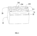
FIG. 1 is an isometric view of showing a large capacity lithium-ion-battery pack, in accordance with a first embodiment of the present invention. -
FIG. 2 is an isometric view of showing the large capacity lithium-ion-battery pack ofFIG. 1 , which a cover member is moved away. -
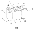
FIG. 3 is an isometric, schematic view of showing a number of single lithium ion batteries connected with a conductive connecting assembly of the large capacity lithium-ion-battery pack ofFIG. 1 . -
FIG.4 is similar toFIG. 3 , but viewed from another angle. -
FIG. 5 is a cross sectional view of a single lithium ion battery ofFIG. 3 . -
FIG. 6 is an isometric view of showing the conductive connecting assembly of the large capacity lithium-ion-battery pack ofFIG. 3 . -
FIG. 7 is a top view of the large capacity lithium-ion-battery pack ofFIG. 1 . -
FIG. 8 is a bottom view of the large capacity lithium-ion-battery pack ofFIG.1 -
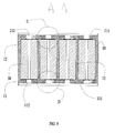
FIG. 9 is a cross sectional view along line A-A of the large capacity lithium-ion battery pack ofFIG.7 -
FIG. 10 is a cross sectional view along line B-B of the large capacity lithium-ion battery pack ofFIG.7 -
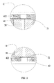
FIG. 11 is an enlarged view of a circled portion C and a circle portion D ofFIG. 9 . -
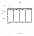
FIG. 12 is a cross sectional view of showing a large capacity lithium-ion-battery pack, in accordance with a second embodiment of the present invention. -
FIG. 13 is an enlarged view of a circled portion E ofFIG. 12 . -
FIG. 14 is an isometric view of showing covering portions of a cover member of the large capacity lithium-ion-battery pack ofFIG. 13 . -
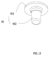
FIG. 15 is an isometric view of showing an electrical pole of a cover member of the large capacity lithium-ion-battery pack ofFIG. 13 . -
FIG. 16 is an isometric view of showing a clamping plate of a cover member of the large capacity lithium-ion-battery pack ofFIG. 13 . - Embodiments of present disclosure will now be described in detail below and with reference to the drawings.
-
FIG. 1 to FIG. 4 show a large capacity lithium-ion-battery pack 100, according to a first embodiment. The large capacity lithium-ion-battery pack 100 includes ahousing 10, acover member 20, a number of singlelithium ion batteries 30, a conductive connecting assembly 40 (FIG. 6 ), and twoelectrode poles 50. - Also referring to
FIG. 5 to FIG. 9 , thehousing 10 is made of plastic and substantially cuboid. Thehousing 10 includes abottom wall 11 and aside wall 12 extending from four sides of thebottom wall 11. A number of receivingbarrels 13 are positioned on thebottom wall 11. Eachreceiving barrel 13 is cylindrical and has an opening at one end away from thebottom wall 11. The receivingbarrels 13 and theside wall 12 cooperatively form a number of areceiving space 14. In the embodiment, each receivingbarrel 13 is separated from another receivingbarrel 13. An enhancingrib 15 connects between tworeceiving barrels 13. Thereceiving barrels 13 are made of polypropylene or polyethylene, which are anti-corrosion from lithium ion electrolyte. One surface opposite to theside wall 12 of thebottom wall 11 defines a number of lowerfluid leading grooves 111. Thebottom wall 11 also defines a number oflower welding holes 112,lower safety holes 113, and lowerfluid passing holes 114 in each lowerfluid leading groove 111. All of thelower welding holes 112,lower safety holes 113, and lowerfluid passing holes 114 are through holes. - The
cover member 20 is made of plastic and substantially rectangular and is configured to assemble to one side of thehousing 10 away from thebottom wall 11. Thecover member 20 includes anupper surface 21 and alower surface 22 opposite to theupper surface 21 for attaching to thehousing 10. Theupper surface 21 defines a number of upperfluid leading grooves 211. Thecover member 20 also defines a number ofupper welding holes 212,upper safety holes 213, and upperfluid passing holes 214 in each upperfluid leading groove 211. All of theupper welding holes 212,upper safety holes 213, and upperfluid passing holes 214 are through holes extending to thelower surface 22. - Each single
lithium ion battery 30 is cylindrical and receives lithium ion electrolyte. A diameter of each singlelithium ion battery 30 corresponds to an inner diameter of eachreceiving barrel 13. In alternative embodiments, the singlelithium ion battery 30 can be cuboid or other shapes, and accordingly thereceiving barrel 13 is cuboid or other shapes. The singlelithium ion batteries 30 received in thereceiving barrels 13 and each can be electrically connected with other singlelithium ion batteries 30 in two manners of in parallel connection or in series connection. There are also a number ofheat dissipation pipes 60 disposed on the top or bottom of the receivingbarrels 13 accommodating singlelithium ion batteries 30 in parallel connection. Theheat dissipation pipes 60 communicate thereceiving barrels 13 accommodating singlelithium ion batteries 30 in parallel connection. Theheat dissipation pipes 60 can be various structures. In the embodiment, theheat dissipation pipes 60 disposed on bottom of thereceiving barrels 13 accommodating singlelithium ion batteries 30 in parallel connection. Theheat dissipation pipes 60 are made from bent copper pipes. - Each single
lithium ion battery 30 includes ananode electrode plate 31 and acathode electrode plate 32 wrapped with and insulated from each other. Ananode currency collector 71 and a cathode currency collector 72 (as shown inFIG. 11 ) are welded (for example, by ultrasonic welding, resistance welding, or laser welding) on two ends and respectively electrically connected to theanode electrode plate 31 and acathode electrode plate 32 of each singlelithium ion battery 30. - The conductive connecting assembly 40 includes a number of
upper contact plates 41 and a number oflower contact plates 42 identical with theupper contact plates 41. Theupper contact plates 41 and thelower contact plates 42 are made of metal such as copper by stamping. Eachupper contact plate 41 includes a substantially rectangularupper base portion 411. At least oneupper contact portion 412 protrudes on a surface of theupper base portion 411, namely eachupper contact portion 412 is a protrusion on theupper base portion 411. There is also anupper connection arm 413 electrically connecting two neighboringupper contact plates 41 of part of all of theupper contact plates 41. An area of theupper connection arm 413 is far less than an area ofupper base portion 411. Therefore, when current pass through theupper connection arm 413 exceeds a predetermined value, theupper connection arm 413 will fuse. Eachupper base portion 411 also includes anupper safety film 414. In the embodiment theupper safety film 414 is integrally formed with theupper base portion 411 and thinner than theupper base portion 411. - Each
lower contact plate 42 includes a substantially rectangularlower base portion 421. At least onelower contact portion 422 protrudes on a surface of thelower base portion 421, namely eachlower contact portion 422 is a protrusion on thelower base portion 421. There is also alower connection arm 423 electrically connecting two neighboringlower contact plates 42 of part of all of thelower contact plates 42. An area of thelower connection arm 423 is far less than an area oflower base portion 421. Therefore, when current pass through thelower connection arm 423 exceeds a predetermined value, thelower connection arm 423 will fuse. Eachlower base portion 421 also includes alower safety film 424. In the embodiment, thelower safety film 424 is integrally formed with thelower base portion 421 and thinner than thelower base portion 421. - The two
electrode poles 50 are made of metal and include a cylindricalanode electrode pole 51 and a cylindricalcathode electrode pole 52. - When manufacturing the large capacity lithium-ion-
battery pack 100, metallic members are firstly made. Metallic members include the conductive connecting assembly 40, the twoelectrode poles 50, and theheat dissipation pipes 60. Then a part of the metallic members are respectively positioned in injection molds for forming thehousing 10 and thecover member 20. Specially, theupper contact plates 41, theanode electrode pole 51, and thecathode electrode pole 52 are positioned in the injection mold for forming thecover member 20. Thelower contact plates 42 and theheat dissipation pipes 60 are positioned in the injection mold for forming thehousing 10. In alternative embodiments, thedissipation pipes 60 can be positioned in the mold for forming thecover member 20 or simultaneously positioned in the molds for forming thehousing 10 and thecover member 20. Then, thehousing 10 and thecover member 20 are formed by an injection molding process with metallic members being embedded therein. - During the injection molding process, the lower
fluid leading grooves 111 are formed on one surface opposite to theside wall 12 of thebottom wall 11. The lower welding holes 112, thelower safety holes 113, and the lowerfluid passing holes 114 are formed in each lowerfluid leading groove 111. The upperfluid leading grooves 211 are formed on theupper surface 21. The upper welding holes 212, the upper safety holes 213, and the upperfluid passing holes 214 are formed in each upperfluid leading groove 211. - The
upper contact plates 41 are embedded in thecover member 20 with theupper base portion 411 being buried in thecover member 20 and theupper contact portion 412 and theupper safety film 414 protruding out from thecover member 20. Theupper connection arms 413 are buried in thecover member 20 and eachupper connection arm 413 connects two correspondingupper contact plates 41 of part of all of theupper contact plates 41. Theupper contact portion 412 is under thelower surface 22 and corresponds to ananode electrode plate 31 or acathode electrode plate 32. Thelower contact plates 42 are embedded in thebottom wall 11 with thelower base portion 421 being buried in thebottom wall 11, and thelower contact portion 422 and thelower safety film 424 protruding out from one surface opposite to the lowerfluid leading grooves 111 of thebottom wall 11. Thelower contact portion 422 is positioned at the bottom of a receivingbarrel 13 for corresponding to ananode electrode plate 31 or acathode electrode plate 32. Thelower connection arms 423 are buried inbottom wall 11 and eachlower connection arm 423 connects two correspondinglower contact plates 42 of part of all of thelower contact plates 42. - All of the single
lithium ion batteries 30 are accommodated in the receivingbarrels 13 respectively. Theanode currency collector 71 or thecathode currency collector 72 on one end of each singlelithium ion battery 30 contacts with thelower contact portion 422 of a correspondinglower contact plate 42. Eachlower welding hole 112 corresponds to alower contact portion 422. Thelower contact portion 422 is connected with theanode currency collector 71 or thecathode currency collector 72 on one end of each singlelithium ion battery 30 by laser welding via thelower welding hole 112. Eachlower safety hole 113 corresponds to alower safety film 424. Each lowerfluid passing hole 114 corresponds to a receivingspace 14. - Then the
cover member 20 is assembled to thehousing 10 with thelower surface 22 facing and attaching on thehousing 10. The other end of each singlelithium ion battery 30 faces thecover member 20. Theanode currency collector 71 or thecathode currency collector 72 on the other end of each singlelithium ion battery 30 contacts with theupper contact portion 412 of a correspondingupper contact plate 41. Eachupper welding hole 212 corresponds to anupper contact portion 412. Theupper contact portion 412 is connected with theanode currency collector 71 or thecathode currency collector 72 on the other end of each singlelithium ion battery 30 by laser welding via theupper welding hole 212. Eachupper safety hole 213 corresponds to anupper safety film 414. Each upperfluid passing hole 214 also corresponds to a receivingspace 14. Theupper contact plates 41 and thelower contact plates 42 are disposed at two opposite ends of the singlelithium ion batteries 30. - Finally, the upper
fluid leading grooves 111 and the lowerfluid leading grooves 211 are enclosed by enclosure trips (not show). Thecover member 20 and thehousing 10 are welded together by laser welding. Lithium ion electrolyte is injected in the receivingbarrels 13 through the upperfluid passing holes 214 and then the upperfluid passing holes 214 are enclosed again. Protective plates are assembled to the outside of thehousing 10 such the large capacity lithium-ion-battery pack 100 is manufactured. All of the singlelithium ion batteries 30 are in a series-parallel connection state through the conductive connecting assembly 40 for providing a high voltage power source. Theanode electrode pole 51 and thecathode electrode pole 52 are embedded in thecover member 20 and electrically connected to the anode and the cathode of the high voltage power source. Loads can be electrically connected theanode electrode pole 51 and thecathode electrode pole 52. -
FIG. 12 to FIG. 16 show a large capacity lithium-ion-battery pack 300, according to a second embodiment. The large capacity lithium-ion-battery pack 300 is similar to the large capacity lithium-ion-battery pack 100 except that theupper contact plates 41 embedded in thecover member 90 are not welded to the singlelithium ion batteries 30. Thecover member 90 is pluggable from the end of each singlelithium ion battery 30 facing thecover member 90. - The
cover member 90 of large capacity lithium-ion-battery pack 300 includes alower surface 91 facing thehousing 10. A number ofcap units 92 connected with each other extend from thelower surface 91. Eachcap unit 92 is substantially hollow cylindrical and receives a metallicconductive post 93. Eachcap unit 92 is configured to cap on one end facing thecover member 90 of a receivingbarrel 13. Theconductive post 93 includes a circularmain portion 931 and acylindrical insertion pin 932 extending from the center of one surface of themain portion 931. Themain portion 931 is clamped in arespective cap unit 92. The other surface away from theinsertion pin 932 of themain portion 931 electrically contacts with theupper contact portion 412 of a respectiveupper contact plate 41. - Each single
lithium ion battery 30 includes a dielectrictop holder 33 disposed at the end facing thecover member 90 of each singlelithium ion battery 30. Aconductive clamping element 34 is mounted in the center of thetop holder 33. The clampingelement 34 is in an opening drum-like shape. A diameter of the clampingelement 34 in the middle is less than those of two ends. The clampingelement 34 defines aninsertion space 341 for receiving theinsertion pin 932. The clampingelement 34 is welded to theanode currency collector 71 or thecathode currency connector 71 on the end facing thecover member 90 of the singlelithium ion battery 30. When thecover member 90 is assembled to thehousing 10, theinsertion pin 932 is inserted into theinsertion space 341 and electrically contacts with the clampingelement 34. Therefore, theupper contact portion 412 of eachupper contact plate 41 is electrically connected to theanode currency collector 71 or the cathode currency connector 71 (on the end facing thecover member 90 of the singlelithium ion battery 30 through theinsertion pin 932 and the clampingelement 34. Thecap unit 92 further defines a fluid injection hole (not show) such lithium ion electrolyte can be injected to a respective singlelithium ion battery 30. -
FIG. 3 andFIG. 4 distinctly illustrate an embodiment that eight singlelithium ion batteries 30 are in a series-parallel connection state through the conductive connecting assembly 40, in according with the present disclosure. As shown inFIG. 3 , the eight signlithium ion batteries 30 are labeled as I, II,III, IV,V, VI,VII, and VIII. Firstly, two upper contact plates each include one upper contact portion are used to connect the anodes of the batteries I and III, then two lower contact plates each includes two lower contact portions are used connects the cathodes of the batteries I and III and connect the anodes of the batteries II and IV. Then two upper contact plates each includes two upper contact portion are used connects the cathodes of the batteries II and IV and connect the anodes of the batteries V and VII. Then two lower contact plates each includes two lower contact portion are used connects the cathodes of the batteries V and VII and connect the anodes of the batteries VI and VIII. Finally an upper contact plates includes two upper contact portions are used to connect the cathodes of the batteries VI and VIII. - The batteries I and III are connected with each other in parallel through an upper connection arm and a lower connection arm. The batteries II and IV are connected with each other in parallel each other through an upper connection arm and a lower connection arm. The batteries V and VII are connected with each other in parallel each other through an upper connection arm and a lower connection arm. The batteries VI and VIII are connected with each other in parallel through a lower connection arm. The batteries I and III are connected to batteries II and IV, batteries V and VII, and the batteries VI and VIII in series. The anode
electrical pole 51 is connected to the upper contact plate on the battery I. The cathodeelectrical pole 52 is connected to the upper contact plate on the battery VIII. - The large capacity lithium-ion-battery pack performs at least following advantages compared to conventional battery group. (1) Because the conductive connecting assembly is embedded in the housing and the cover member, it is easy to manufacture related to use screws such that the production efficiency is improved. (2) The upper connection arm or the lower connection arm will fuse when the current exceed the predetermined value, it makes the large capacity lithium-ion-battery pack safer to use. (3) It no need of providing a steel shell and covers for each signal lithium ion battery compared with a conventional signal lithium ion battery. Therefore, the cost is reduced. (4) The single lithium ion batteries connected in parallel are communicated with each other, when one of them break down and generate heat, heat can be translated to other single lithium ion batteries. Therefore, it is safer to use. (5) It convenient to maintain, for example, when one of single lithium ion batteries need to be change, it is just need move the cover member and then change the single lithium ion battery.
- It will be apparent to those skilled in the art that various modification and variations can be made in the multicolor illumination device and related method of the present invention without departing from the spirit or scope of the invention. Thus, it is intended that the present invention cover modifications and variations that come within the scope of the appended claims and their equivalents.
Claims (12)
- A large capacity lithium-ion-battery pack (100) comprising:an dielectric housing (10) comprising a number of receiving barrels (13);a number of single lithium ion batteries (30), each single lithium battery being received in a respective receiving barrel (13), and each single lithium battery comprising an anode currency collector (71) and a cathode currency collector (72) mounted at two ends of the single lithium battery;a dielectric cover member (20) assembled to the housing ;two electrode poles (50); anda conductive connecting assembly (40) comprising:a number of upper contact plates (41) embedded in the cover member (20) by injection molding and a number of lower contact plates (42) embedded in the housing (10) by injection molding, the upper contact plates (41) and the lower contact plates (42) respectively being disposed at two opposite ends of the single lithium ion batteries;wherein a part of each upper contact plate (41) protrude out of the cover member (20) for electrically contacting the anode currency collector (71) or the cathode currency collector (72) of a corresponding single lithium ion battery, a part of each lower contact plate (42) protrude out of the housing (10) for electrically contacting the anode currency collector (71) or the cathode currency collector (72) of a corresponding single lithium battery, all of the single lithium ion batteries are in a series-parallel connection state through the conductive connecting assembly (40), and the two electrode poles (50) are respectively electrically connected to the anode and the cathode of all of the single lithium ion batteries connected in a series-parallel connection state.
- The large capacity lithium-ion-battery pack as claimed in claim 1, wherein the housing (10) is made of plastic and substantially cuboid, the housing (10) comprises a bottom wall (11) and a side wall (12) extending from sides of the bottom wall (11), the receiving barrels (13) are positioned on the bottom wall (11), each receiving barrel (13) is cylindrical and has an opening at one end away from the bottom wall (11); the receiving barrels (13) and the side wall (12) cooperatively form a number of a receiving space (14), each receiving barrel (13) is separated from another receiving barrel, and an enhancing rib (15) connects between two receiving barrels.
- The large capacity lithium-ion-battery pack as claimed in claim 2, wherein the upper contact plates (41) are identical with the lower contact plates (42) and made of metal by stamping, each upper contact plate (41) comprises a rectangular upper base portion (411), at least one upper contact portion (412) protruding on a surface of the upper base portion (411); each lower contact plate (42) comprise a rectangular lower base portion (421), at least one lower contact portion (422) protruding on a surface of the lower base portion (421).
- The large capacity lithium-ion-battery pack as claimed in claim 3, wherein an upper connection arm (413) electrically connecting two neighboring upper contact plates (41) of part of all of the upper contact plates, an area of the upper connection arm (413) is far less than an area of upper base portion (411); a lower connection arm (423) electrically connecting two neighboring lower contact plates (42) of part of all of the lower contact plates, an area of the lower connection arm (423) is far less than an area of lower base portion (421).
- The large capacity lithium-ion-battery pack as claimed in claim 4, wherein each upper base portion (411) also comprises an upper safety film (414), the upper safety film (414) is integrally formed with the upper base portion (411) and thinner than the upper base portion (411); each lower base portion (421) also comprises a lower safety film (424), the lower safety film (424) is integrally formed with the lower base portion (421) and thinner than the lower base portion (421).
- The large capacity lithium-ion-battery pack as claimed in claim 5, wherein the at least one upper contact portion (412) and the upper safety film (414)are the part of each upper contact plate (41) protruding out of the cover; the at least one lower contact portion (422) and the lower safety film (424) are the part of each lower contact plate (42) protruding out of the housing (10), each upper contact portion (412) and each lower contact portion (422) electrically contacts the anode currency collector (71) and the cathode currency collector (72) of a corresponding single lithium battery.
- The large capacity lithium-ion-battery pack as claimed in claim 6, wherein the cover member (20) is mounted to a side away from the bottom wall (11) of the housing (10), the cover member (20) comprises an upper surface and a lower surface opposite to the upper surface for attaching to the housing, the upper surface defines a number of upper fluid leading grooves (211), the cover member (20) also defines a number of upper welding holes (212), upper safety holes (213), and upper fluid passing holes (214) in each upper fluid leading groove (211), all of the upper welding holes (212), the upper safety holes (213), and the upper fluid passing holes (214) are through holes extending to the lower surface; each upper welding hole (212) corresponds to an upper contact portion (412), the upper contact portion (412) is connected with the anode currency collector (71) or the cathode currency collector (72) on the end of each single lithium ion battery by laser welding via the upper welding hole (212), each upper safety hole (213) corresponds to an upper safety film (414), and each upper fluid passing hole (214) corresponds to a receiving space (14).
- The large capacity lithium-ion-battery pack as claimed in claim 6, wherein one surface opposite to the side wall of the bottom wall (11) defines a number of lower fluid leading grooves (111); the bottom wall (11) also defines a number of lower welding holes (112), lower safety holes (113), and lower fluid passing holes in each lower fluid leading groove, all of the lower welding holes (112), the lower safety holes (113), and the lower fluid passing holes are through holes; each lower welding hole (112) corresponds to a lower contact portion (422), the lower contact portion (422) is connected with the anode currency collector (71) or the cathode currency collector (72) on one end of each single lithium ion battery by laser welding via the lower welding hole (112), each lower safety hole (113) corresponds to a lower safety film (424), and each lower fluid passing hole corresponds to a receiving space (14).
- The large capacity lithium-ion-battery pack as claimed in claim 1, wherein the cover member (90) comprises a lower surface (91) facing the housing, a number of cap units (92) connected with each other extend from the lower surface (91), each cap unit (92) is hollow cylindrical and receives a metallic conductive post (93), and each cap unit (92) is configured to cap on one end facing the cover member (90) of a receiving barrel.
- The large capacity lithium-ion-battery pack as claimed in claim 9, wherein the conductive post (93) comprises a circular main portion (931) and a cylindrical insertion pin (932) extending from the center of one surface of the main portion (931), the main portion (931) is clamped in a respective cap unit (92) and electrically contacts with the upper contact portion of a respective upper contact plate (41); each single lithium ion battery comprises a dielectric top holder (33) disposed at the end facing the cover member (90), a conductive clamping element (34) is mounted in the center of the top holder (33), the clamping element (34) is in an opening drum-like shape and defines an insertion space for receiving the insertion pin (932), and the insertion pin (932) is inserted into the insertion space and electrically contacts with the clamping element (34).
- The large capacity lithium-ion-battery pack as claimed in claim 1, wherein a number of heat dissipation pipes (60) disposed on the bottom of the receiving barrels accommodating single lithium ion batteries in parallel connection, the dissipation pipes (60) communicate the receiving barrels accommodating single lithium ion batteries in parallel connection.
- The large capacity lithium-ion-battery pack as claimed in claim 11, wherein the heat dissipation pipes (60) are made from bent copper pipes.
Applications Claiming Priority (1)
| Application Number | Priority Date | Filing Date | Title |
|---|---|---|---|
| CN201310350387.9A CN104377335B (en) | 2013-08-12 | 2013-08-12 | High capacity lithium ion battery bag |
Publications (2)
| Publication Number | Publication Date |
|---|---|
| EP2837523A1 true EP2837523A1 (en) | 2015-02-18 |
| EP2837523B1 EP2837523B1 (en) | 2018-03-07 |
Family
ID=51301171
Family Applications (1)
| Application Number | Title | Priority Date | Filing Date |
|---|---|---|---|
| EP14180640.6A Not-in-force EP2837523B1 (en) | 2013-08-12 | 2014-08-12 | Large capacity lithium-ion-battery pack |
Country Status (3)
| Country | Link |
|---|---|
| US (1) | US9979046B2 (en) |
| EP (1) | EP2837523B1 (en) |
| CN (1) | CN104377335B (en) |
Families Citing this family (14)
| Publication number | Priority date | Publication date | Assignee | Title |
|---|---|---|---|---|
| KR101393167B1 (en) | 2009-05-20 | 2014-05-08 | 존슨 컨트롤즈 테크놀로지, 엘엘씨 | Lithium ion battery module |
| DE102015215597B4 (en) * | 2015-08-14 | 2021-05-20 | Audi Ag | Energy storage arrangement, in particular for a motor vehicle, motor vehicle and method for producing an energy storage receptacle for an energy storage arrangement |
| CN106608193B (en) * | 2015-10-23 | 2019-01-18 | 深圳格林德能源有限公司 | A kind of series-parallel dynamical system with ultimate self-balancing of supper-intelligent dynamic |
| JP6414577B2 (en) * | 2016-09-16 | 2018-10-31 | トヨタ自動車株式会社 | Stacked battery |
| CN206076357U (en) * | 2016-10-14 | 2017-04-05 | 宁德时代新能源科技股份有限公司 | Battery modules |
| EP3799178A4 (en) * | 2018-05-21 | 2021-08-18 | Panasonic Intellectual Property Management Co., Ltd. | FLOW BATTERY |
| CN109103034B (en) * | 2018-07-10 | 2020-10-02 | 宁波中车新能源科技有限公司 | A blowout-proof fixing frame for fixing a supercapacitor module |
| AT521581B1 (en) * | 2018-08-24 | 2020-07-15 | Raiffeisenlandesbank Oberoesterreich Ag | Contacting device for battery cells assembled into a module |
| US11145932B2 (en) | 2018-09-24 | 2021-10-12 | Milwaukee Electric Tool Corporation | Battery cell module and battery pack |
| CN110854322A (en) * | 2019-09-20 | 2020-02-28 | 杭州乾代科技有限公司 | Modularized lithium battery module |
| DE102020110012A1 (en) | 2020-04-09 | 2021-10-14 | Bayerische Motoren Werke Aktiengesellschaft | Electric energy storage device and motor vehicle |
| CN111640890A (en) * | 2020-06-01 | 2020-09-08 | 江西优特汽车技术有限公司 | Design method of portable diagnosis power supply |
| CN111900289A (en) * | 2020-07-22 | 2020-11-06 | 福建东方醒狮新能源有限公司 | Safety solid battery |
| DE102021106344A1 (en) | 2021-03-16 | 2022-09-22 | Bayerische Motoren Werke Aktiengesellschaft | Round cell battery module comprising round cell battery units and a cell connection device, vehicle and cell connection device |
Citations (3)
| Publication number | Priority date | Publication date | Assignee | Title |
|---|---|---|---|---|
| DE102007010745A1 (en) * | 2007-02-27 | 2008-08-28 | Daimler Ag | Battery has heating plate for tempering battery and heating plate has bores in area of pole of solitary cells, and pole of individual cells extends through bores |
| EP2202824A1 (en) * | 2008-03-04 | 2010-06-30 | Panasonic Corporation | Battery module and battery pack using said battery module |
| US20100323228A1 (en) * | 2008-09-26 | 2010-12-23 | Takeshi Okamoto | Lead acid battery manufacturing method and lead acid battery |
Family Cites Families (14)
| Publication number | Priority date | Publication date | Assignee | Title |
|---|---|---|---|---|
| US2836642A (en) * | 1956-10-22 | 1958-05-27 | Bauer Rudolf Erich | Dry battery assembly |
| GB1602610A (en) * | 1977-08-11 | 1981-11-11 | Ching Wa Pun | Electric batteries |
| US4346151A (en) * | 1980-12-29 | 1982-08-24 | The Gates Rubber Company | Multicell sealed rechargeable battery |
| KR100662165B1 (en) * | 2001-08-06 | 2006-12-27 | 마츠시타 덴끼 산교 가부시키가이샤 | Square sealed battery |
| EP1689009A1 (en) * | 2005-02-04 | 2006-08-09 | Yao, Li-ho | Battery pack |
| CN100470916C (en) * | 2005-11-08 | 2009-03-18 | 比亚迪股份有限公司 | Lithium-ion secondary battery |
| CN101471520A (en) * | 2007-12-25 | 2009-07-01 | 英业达股份有限公司 | Shell structure integrated with power supply conductive module and electronic device applied to shell structure |
| US20110177381A1 (en) * | 2008-11-07 | 2011-07-21 | Mitsubishi Heavy Industries, Ltd. | Bus bar for secondary battery and secondary battery module |
| KR101393167B1 (en) * | 2009-05-20 | 2014-05-08 | 존슨 컨트롤즈 테크놀로지, 엘엘씨 | Lithium ion battery module |
| AT508742B1 (en) * | 2009-09-10 | 2011-07-15 | Norman Neuhold | INSERT FOR AN ACCUMULATOR PART |
| US20130224532A1 (en) * | 2010-11-05 | 2013-08-29 | Alelion Batteries Ab | Battery assembly |
| CN202067850U (en) * | 2011-05-18 | 2011-12-07 | 深圳市倍特力电池有限公司 | Combined type battery |
| TWI371883B (en) * | 2011-07-08 | 2012-09-01 | Simplo Technology Company Ltd | Battery module and related forming method,battery cell assembly,bus layout structure of a battery module and related layout method,cpnnection structure and connection method between battery cells and conductiog buses of a battery module, and connection s |
| CN203521509U (en) * | 2013-08-12 | 2014-04-02 | 深圳市沃特玛电池有限公司 | High-capacity lithium ion battery pack |
-
2013
- 2013-08-12 CN CN201310350387.9A patent/CN104377335B/en not_active Expired - Fee Related
-
2014
- 2014-08-11 US US14/457,072 patent/US9979046B2/en not_active Expired - Fee Related
- 2014-08-12 EP EP14180640.6A patent/EP2837523B1/en not_active Not-in-force
Patent Citations (3)
| Publication number | Priority date | Publication date | Assignee | Title |
|---|---|---|---|---|
| DE102007010745A1 (en) * | 2007-02-27 | 2008-08-28 | Daimler Ag | Battery has heating plate for tempering battery and heating plate has bores in area of pole of solitary cells, and pole of individual cells extends through bores |
| EP2202824A1 (en) * | 2008-03-04 | 2010-06-30 | Panasonic Corporation | Battery module and battery pack using said battery module |
| US20100323228A1 (en) * | 2008-09-26 | 2010-12-23 | Takeshi Okamoto | Lead acid battery manufacturing method and lead acid battery |
Also Published As
| Publication number | Publication date |
|---|---|
| US9979046B2 (en) | 2018-05-22 |
| CN104377335B (en) | 2017-07-07 |
| EP2837523B1 (en) | 2018-03-07 |
| US20150044539A1 (en) | 2015-02-12 |
| CN104377335A (en) | 2015-02-25 |
Similar Documents
| Publication | Publication Date | Title |
|---|---|---|
| EP2837523B1 (en) | Large capacity lithium-ion-battery pack | |
| CN107710450B (en) | Battery module and battery pack including battery module | |
| US20230261278A1 (en) | Battery pack and vehicle comprising same | |
| EP3570347A1 (en) | Battery module having guide coupling structure and battery pack comprising same | |
| EP2672284B1 (en) | Voltage sensing assembly and battery module having same | |
| KR100890178B1 (en) | High Capacity Lithium Ion Secondary Battery with Metal Casing | |
| EP3376559A1 (en) | Battery module | |
| CN110970585A (en) | Battery cell assemblies, battery modules, battery packs and vehicles | |
| KR20190071454A (en) | Battery Module Having Bus bar Assembly | |
| JP2022513581A (en) | Coin-type lithium-ion battery and its manufacturing method | |
| JP7295096B2 (en) | battery pack | |
| EP2775550B1 (en) | Manufacturing method for battery cells | |
| JP6454423B2 (en) | Battery cell and battery system | |
| KR20140090459A (en) | Rechargeable battery pack | |
| KR20130053026A (en) | Rechargeable battery | |
| KR20150032086A (en) | Rechargeable battery having safty member | |
| US10615383B2 (en) | Battery module, and battery pack and vehicle comprising same | |
| KR101233514B1 (en) | Secondary battery | |
| CN203521509U (en) | High-capacity lithium ion battery pack | |
| KR101039518B1 (en) | Battery cell connection member | |
| GB2544363A (en) | Prismatic accumulator cell and accumulator pack | |
| KR102817994B1 (en) | The capacitor module | |
| CN223871583U (en) | Battery Module | |
| CN221574035U (en) | Battery monomer, shell assembly and battery module | |
| KR102459671B1 (en) | Electric energy storage moulde |
Legal Events
| Date | Code | Title | Description |
|---|---|---|---|
| 17P | Request for examination filed |
Effective date: 20140812 |
|
| AK | Designated contracting states |
Kind code of ref document: A1 Designated state(s): AL AT BE BG CH CY CZ DE DK EE ES FI FR GB GR HR HU IE IS IT LI LT LU LV MC MK MT NL NO PL PT RO RS SE SI SK SM TR |
|
| AX | Request for extension of the european patent |
Extension state: BA ME |
|
| PUAI | Public reference made under article 153(3) epc to a published international application that has entered the european phase |
Free format text: ORIGINAL CODE: 0009012 |
|
| R17P | Request for examination filed (corrected) |
Effective date: 20150814 |
|
| RBV | Designated contracting states (corrected) |
Designated state(s): AL AT BE BG CH CY CZ DE DK EE ES FI FR GB GR HR HU IE IS IT LI LT LU LV MC MK MT NL NO PL PT RO RS SE SI SK SM TR |
|
| RIC1 | Information provided on ipc code assigned before grant |
Ipc: H01M 2/02 20060101ALI20170705BHEP Ipc: B60L 11/18 20060101AFI20170705BHEP Ipc: H01M 2/34 20060101ALI20170705BHEP Ipc: H01M 2/10 20060101ALI20170705BHEP Ipc: H01M 10/0525 20100101ALI20170705BHEP Ipc: H01M 10/6552 20140101ALI20170705BHEP Ipc: H01M 2/20 20060101ALI20170705BHEP Ipc: H01M 2/30 20060101ALI20170705BHEP Ipc: H01M 10/6553 20140101ALI20170705BHEP Ipc: H01M 2/12 20060101ALI20170705BHEP Ipc: H01M 2/04 20060101ALI20170705BHEP |
|
| GRAP | Despatch of communication of intention to grant a patent |
Free format text: ORIGINAL CODE: EPIDOSNIGR1 |
|
| INTG | Intention to grant announced |
Effective date: 20170922 |
|
| RIN1 | Information on inventor provided before grant (corrected) |
Inventor name: LI, YAO |
|
| GRAS | Grant fee paid |
Free format text: ORIGINAL CODE: EPIDOSNIGR3 |
|
| GRAA | (expected) grant |
Free format text: ORIGINAL CODE: 0009210 |
|
| AK | Designated contracting states |
Kind code of ref document: B1 Designated state(s): AL AT BE BG CH CY CZ DE DK EE ES FI FR GB GR HR HU IE IS IT LI LT LU LV MC MK MT NL NO PL PT RO RS SE SI SK SM TR |
|
| REG | Reference to a national code |
Ref country code: GB Ref legal event code: FG4D |
|
| REG | Reference to a national code |
Ref country code: CH Ref legal event code: EP Ref country code: AT Ref legal event code: REF Ref document number: 976180 Country of ref document: AT Kind code of ref document: T Effective date: 20180315 |
|
| REG | Reference to a national code |
Ref country code: IE Ref legal event code: FG4D |
|
| REG | Reference to a national code |
Ref country code: DE Ref legal event code: R096 Ref document number: 602014021891 Country of ref document: DE |
|
| REG | Reference to a national code |
Ref country code: NL Ref legal event code: MP Effective date: 20180307 |
|
| REG | Reference to a national code |
Ref country code: LT Ref legal event code: MG4D |
|
| PG25 | Lapsed in a contracting state [announced via postgrant information from national office to epo] |
Ref country code: FI Free format text: LAPSE BECAUSE OF FAILURE TO SUBMIT A TRANSLATION OF THE DESCRIPTION OR TO PAY THE FEE WITHIN THE PRESCRIBED TIME-LIMIT Effective date: 20180307 Ref country code: HR Free format text: LAPSE BECAUSE OF FAILURE TO SUBMIT A TRANSLATION OF THE DESCRIPTION OR TO PAY THE FEE WITHIN THE PRESCRIBED TIME-LIMIT Effective date: 20180307 Ref country code: NO Free format text: LAPSE BECAUSE OF FAILURE TO SUBMIT A TRANSLATION OF THE DESCRIPTION OR TO PAY THE FEE WITHIN THE PRESCRIBED TIME-LIMIT Effective date: 20180607 Ref country code: ES Free format text: LAPSE BECAUSE OF FAILURE TO SUBMIT A TRANSLATION OF THE DESCRIPTION OR TO PAY THE FEE WITHIN THE PRESCRIBED TIME-LIMIT Effective date: 20180307 Ref country code: LT Free format text: LAPSE BECAUSE OF FAILURE TO SUBMIT A TRANSLATION OF THE DESCRIPTION OR TO PAY THE FEE WITHIN THE PRESCRIBED TIME-LIMIT Effective date: 20180307 Ref country code: CY Free format text: LAPSE BECAUSE OF FAILURE TO SUBMIT A TRANSLATION OF THE DESCRIPTION OR TO PAY THE FEE WITHIN THE PRESCRIBED TIME-LIMIT Effective date: 20180307 |
|
| REG | Reference to a national code |
Ref country code: AT Ref legal event code: MK05 Ref document number: 976180 Country of ref document: AT Kind code of ref document: T Effective date: 20180307 |
|
| REG | Reference to a national code |
Ref country code: FR Ref legal event code: PLFP Year of fee payment: 5 |
|
| PG25 | Lapsed in a contracting state [announced via postgrant information from national office to epo] |
Ref country code: BG Free format text: LAPSE BECAUSE OF FAILURE TO SUBMIT A TRANSLATION OF THE DESCRIPTION OR TO PAY THE FEE WITHIN THE PRESCRIBED TIME-LIMIT Effective date: 20180607 Ref country code: SE Free format text: LAPSE BECAUSE OF FAILURE TO SUBMIT A TRANSLATION OF THE DESCRIPTION OR TO PAY THE FEE WITHIN THE PRESCRIBED TIME-LIMIT Effective date: 20180307 Ref country code: LV Free format text: LAPSE BECAUSE OF FAILURE TO SUBMIT A TRANSLATION OF THE DESCRIPTION OR TO PAY THE FEE WITHIN THE PRESCRIBED TIME-LIMIT Effective date: 20180307 Ref country code: GR Free format text: LAPSE BECAUSE OF FAILURE TO SUBMIT A TRANSLATION OF THE DESCRIPTION OR TO PAY THE FEE WITHIN THE PRESCRIBED TIME-LIMIT Effective date: 20180608 Ref country code: RS Free format text: LAPSE BECAUSE OF FAILURE TO SUBMIT A TRANSLATION OF THE DESCRIPTION OR TO PAY THE FEE WITHIN THE PRESCRIBED TIME-LIMIT Effective date: 20180307 |
|
| PG25 | Lapsed in a contracting state [announced via postgrant information from national office to epo] |
Ref country code: EE Free format text: LAPSE BECAUSE OF FAILURE TO SUBMIT A TRANSLATION OF THE DESCRIPTION OR TO PAY THE FEE WITHIN THE PRESCRIBED TIME-LIMIT Effective date: 20180307 Ref country code: NL Free format text: LAPSE BECAUSE OF FAILURE TO SUBMIT A TRANSLATION OF THE DESCRIPTION OR TO PAY THE FEE WITHIN THE PRESCRIBED TIME-LIMIT Effective date: 20180307 Ref country code: PL Free format text: LAPSE BECAUSE OF FAILURE TO SUBMIT A TRANSLATION OF THE DESCRIPTION OR TO PAY THE FEE WITHIN THE PRESCRIBED TIME-LIMIT Effective date: 20180307 Ref country code: AL Free format text: LAPSE BECAUSE OF FAILURE TO SUBMIT A TRANSLATION OF THE DESCRIPTION OR TO PAY THE FEE WITHIN THE PRESCRIBED TIME-LIMIT Effective date: 20180307 Ref country code: IT Free format text: LAPSE BECAUSE OF FAILURE TO SUBMIT A TRANSLATION OF THE DESCRIPTION OR TO PAY THE FEE WITHIN THE PRESCRIBED TIME-LIMIT Effective date: 20180307 Ref country code: RO Free format text: LAPSE BECAUSE OF FAILURE TO SUBMIT A TRANSLATION OF THE DESCRIPTION OR TO PAY THE FEE WITHIN THE PRESCRIBED TIME-LIMIT Effective date: 20180307 |
|
| PG25 | Lapsed in a contracting state [announced via postgrant information from national office to epo] |
Ref country code: CZ Free format text: LAPSE BECAUSE OF FAILURE TO SUBMIT A TRANSLATION OF THE DESCRIPTION OR TO PAY THE FEE WITHIN THE PRESCRIBED TIME-LIMIT Effective date: 20180307 Ref country code: SM Free format text: LAPSE BECAUSE OF FAILURE TO SUBMIT A TRANSLATION OF THE DESCRIPTION OR TO PAY THE FEE WITHIN THE PRESCRIBED TIME-LIMIT Effective date: 20180307 Ref country code: SK Free format text: LAPSE BECAUSE OF FAILURE TO SUBMIT A TRANSLATION OF THE DESCRIPTION OR TO PAY THE FEE WITHIN THE PRESCRIBED TIME-LIMIT Effective date: 20180307 Ref country code: AT Free format text: LAPSE BECAUSE OF FAILURE TO SUBMIT A TRANSLATION OF THE DESCRIPTION OR TO PAY THE FEE WITHIN THE PRESCRIBED TIME-LIMIT Effective date: 20180307 |
|
| REG | Reference to a national code |
Ref country code: DE Ref legal event code: R097 Ref document number: 602014021891 Country of ref document: DE |
|
| PG25 | Lapsed in a contracting state [announced via postgrant information from national office to epo] |
Ref country code: PT Free format text: LAPSE BECAUSE OF FAILURE TO SUBMIT A TRANSLATION OF THE DESCRIPTION OR TO PAY THE FEE WITHIN THE PRESCRIBED TIME-LIMIT Effective date: 20180709 |
|
| PLBE | No opposition filed within time limit |
Free format text: ORIGINAL CODE: 0009261 |
|
| STAA | Information on the status of an ep patent application or granted ep patent |
Free format text: STATUS: NO OPPOSITION FILED WITHIN TIME LIMIT |
|
| REG | Reference to a national code |
Ref country code: DE Ref legal event code: R079 Ref document number: 602014021891 Country of ref document: DE Free format text: PREVIOUS MAIN CLASS: B60L0011180000 Ipc: B60L0050500000 |
|
| PG25 | Lapsed in a contracting state [announced via postgrant information from national office to epo] |
Ref country code: DK Free format text: LAPSE BECAUSE OF FAILURE TO SUBMIT A TRANSLATION OF THE DESCRIPTION OR TO PAY THE FEE WITHIN THE PRESCRIBED TIME-LIMIT Effective date: 20180307 |
|
| 26N | No opposition filed |
Effective date: 20181210 |
|
| PG25 | Lapsed in a contracting state [announced via postgrant information from national office to epo] |
Ref country code: SI Free format text: LAPSE BECAUSE OF FAILURE TO SUBMIT A TRANSLATION OF THE DESCRIPTION OR TO PAY THE FEE WITHIN THE PRESCRIBED TIME-LIMIT Effective date: 20180307 |
|
| PG25 | Lapsed in a contracting state [announced via postgrant information from national office to epo] |
Ref country code: MC Free format text: LAPSE BECAUSE OF FAILURE TO SUBMIT A TRANSLATION OF THE DESCRIPTION OR TO PAY THE FEE WITHIN THE PRESCRIBED TIME-LIMIT Effective date: 20180307 |
|
| REG | Reference to a national code |
Ref country code: CH Ref legal event code: PL |
|
| PG25 | Lapsed in a contracting state [announced via postgrant information from national office to epo] |
Ref country code: LU Free format text: LAPSE BECAUSE OF NON-PAYMENT OF DUE FEES Effective date: 20180812 Ref country code: LI Free format text: LAPSE BECAUSE OF NON-PAYMENT OF DUE FEES Effective date: 20180831 Ref country code: CH Free format text: LAPSE BECAUSE OF NON-PAYMENT OF DUE FEES Effective date: 20180831 |
|
| REG | Reference to a national code |
Ref country code: BE Ref legal event code: MM Effective date: 20180831 |
|
| REG | Reference to a national code |
Ref country code: IE Ref legal event code: MM4A |
|
| PG25 | Lapsed in a contracting state [announced via postgrant information from national office to epo] |
Ref country code: IE Free format text: LAPSE BECAUSE OF NON-PAYMENT OF DUE FEES Effective date: 20180812 |
|
| PG25 | Lapsed in a contracting state [announced via postgrant information from national office to epo] |
Ref country code: BE Free format text: LAPSE BECAUSE OF NON-PAYMENT OF DUE FEES Effective date: 20180831 |
|
| PG25 | Lapsed in a contracting state [announced via postgrant information from national office to epo] |
Ref country code: MT Free format text: LAPSE BECAUSE OF NON-PAYMENT OF DUE FEES Effective date: 20180812 |
|
| PGFP | Annual fee paid to national office [announced via postgrant information from national office to epo] |
Ref country code: DE Payment date: 20191024 Year of fee payment: 6 |
|
| REG | Reference to a national code |
Ref country code: GB Ref legal event code: 732E Free format text: REGISTERED BETWEEN 20200109 AND 20200115 |
|
| PGFP | Annual fee paid to national office [announced via postgrant information from national office to epo] |
Ref country code: FR Payment date: 20191030 Year of fee payment: 6 |
|
| REG | Reference to a national code |
Ref country code: DE Ref legal event code: R081 Ref document number: 602014021891 Country of ref document: DE Owner name: SHENZHEN ANDING NEW ENERGY TECHNOLOGY DEVELOPM, CN Free format text: FORMER OWNER: OPTIMUM BATTERY CO., LTD., SHENZHEN, GUANGDONG, CN Ref country code: DE Ref legal event code: R082 Ref document number: 602014021891 Country of ref document: DE Representative=s name: GRUENECKER PATENT- UND RECHTSANWAELTE PARTG MB, DE |
|
| PG25 | Lapsed in a contracting state [announced via postgrant information from national office to epo] |
Ref country code: TR Free format text: LAPSE BECAUSE OF FAILURE TO SUBMIT A TRANSLATION OF THE DESCRIPTION OR TO PAY THE FEE WITHIN THE PRESCRIBED TIME-LIMIT Effective date: 20180307 |
|
| PGFP | Annual fee paid to national office [announced via postgrant information from national office to epo] |
Ref country code: GB Payment date: 20191030 Year of fee payment: 6 |
|
| PG25 | Lapsed in a contracting state [announced via postgrant information from national office to epo] |
Ref country code: HU Free format text: LAPSE BECAUSE OF FAILURE TO SUBMIT A TRANSLATION OF THE DESCRIPTION OR TO PAY THE FEE WITHIN THE PRESCRIBED TIME-LIMIT; INVALID AB INITIO Effective date: 20140812 |
|
| PG25 | Lapsed in a contracting state [announced via postgrant information from national office to epo] |
Ref country code: MK Free format text: LAPSE BECAUSE OF NON-PAYMENT OF DUE FEES Effective date: 20180307 |
|
| PG25 | Lapsed in a contracting state [announced via postgrant information from national office to epo] |
Ref country code: IS Free format text: LAPSE BECAUSE OF FAILURE TO SUBMIT A TRANSLATION OF THE DESCRIPTION OR TO PAY THE FEE WITHIN THE PRESCRIBED TIME-LIMIT Effective date: 20180707 |
|
| REG | Reference to a national code |
Ref country code: DE Ref legal event code: R119 Ref document number: 602014021891 Country of ref document: DE |
|
| GBPC | Gb: european patent ceased through non-payment of renewal fee |
Effective date: 20200812 |
|
| PG25 | Lapsed in a contracting state [announced via postgrant information from national office to epo] |
Ref country code: DE Free format text: LAPSE BECAUSE OF NON-PAYMENT OF DUE FEES Effective date: 20210302 Ref country code: FR Free format text: LAPSE BECAUSE OF NON-PAYMENT OF DUE FEES Effective date: 20200831 |
|
| PG25 | Lapsed in a contracting state [announced via postgrant information from national office to epo] |
Ref country code: GB Free format text: LAPSE BECAUSE OF NON-PAYMENT OF DUE FEES Effective date: 20200812 |