EP2837472A2 - Robot system, robot control apparatus, method for controlling robot - Google Patents
Robot system, robot control apparatus, method for controlling robot Download PDFInfo
- Publication number
- EP2837472A2 EP2837472A2 EP14179260.6A EP14179260A EP2837472A2 EP 2837472 A2 EP2837472 A2 EP 2837472A2 EP 14179260 A EP14179260 A EP 14179260A EP 2837472 A2 EP2837472 A2 EP 2837472A2
- Authority
- EP
- European Patent Office
- Prior art keywords
- probe
- robot
- actuators
- work stand
- correction amount
- Prior art date
- Legal status (The legal status is an assumption and is not a legal conclusion. Google has not performed a legal analysis and makes no representation as to the accuracy of the status listed.)
- Withdrawn
Links
Images







Classifications
-
- B—PERFORMING OPERATIONS; TRANSPORTING
- B25—HAND TOOLS; PORTABLE POWER-DRIVEN TOOLS; MANIPULATORS
- B25J—MANIPULATORS; CHAMBERS PROVIDED WITH MANIPULATION DEVICES
- B25J9/00—Program-controlled manipulators
- B25J9/16—Program controls
- B25J9/1679—Program controls characterised by the tasks executed
- B25J9/1692—Calibration of manipulator
-
- G—PHYSICS
- G01—MEASURING; TESTING
- G01L—MEASURING FORCE, STRESS, TORQUE, WORK, MECHANICAL POWER, MECHANICAL EFFICIENCY, OR FLUID PRESSURE
- G01L5/00—Apparatus for, or methods of, measuring force, work, mechanical power, or torque, specially adapted for specific purposes
- G01L5/22—Apparatus for, or methods of, measuring force, work, mechanical power, or torque, specially adapted for specific purposes for measuring the force applied to control members, e.g. control members of vehicles, triggers
-
- G—PHYSICS
- G05—CONTROLLING; REGULATING
- G05B—CONTROL OR REGULATING SYSTEMS IN GENERAL; FUNCTIONAL ELEMENTS OF SUCH SYSTEMS; MONITORING OR TESTING ARRANGEMENTS FOR SUCH SYSTEMS OR ELEMENTS
- G05B2219/00—Program-control systems
- G05B2219/30—Nc systems
- G05B2219/39—Robotics, robotics to robotics hand
- G05B2219/39021—With probe, touch reference positions
Definitions
- the present invention relates to a robot system, a robot control apparatus, and a method for controlling a robot.
- Japanese Unexamined Patent Application Publication 11-123682 discloses a visual sensor mounted on a robot that is installed on an automated guided vehicle.
- the visual sensor detects a position of a marker set on a work stand, and based on the detected position of the marker, a position at which the automated guided vehicle is stopped is detected.
- the visual sensor which cannot be used while the robot is working, is provided for the only purpose of detecting the position at which the automated guided vehicle is stopped.
- the present invention has been made in view of the above-described circumstances, and it is an object of the present invention to provide a robot system, a robot control apparatus, and a method for controlling a robot that ensure correction of the position of a work stand relative to a robot without using a visual sensor.
- a robot system includes a robot and a controller.
- the robot includes an arm, a plurality of actuators, a plurality of sensors, a probe, and a force sensor.
- the arm includes a plurality of joints.
- the plurality of actuators are configured to drive the plurality of joints.
- the plurality of sensors are configured to detect operation states of the plurality of actuators.
- the probe is mounted on the arm.
- the force sensor is configured to detect force received by the probe.
- the controller is configured to control the robot, and includes a determination section, an operation state acquisition section, a coordinate calculation section, and a position correction amount calculation section.
- the determination section is configured to determine whether the force received by the probe from a structure disposed at a predetermined position on a work stand satisfies a predetermined condition.
- the operation state acquisition section is configured to acquire the operation states of the plurality of actuators when the force received by the probe satisfies the predetermined condition.
- the coordinate calculation section is configured to calculate a position coordinate of the probe based on the operation states of the plurality of actuators.
- the position correction amount calculation section is configured to calculate a correction amount of a position of the work stand relative to the robot based on the position coordinate of the probe.
- the structure on the work stand may include a plurality of structures.
- the controller may further include a direction correction amount calculation section configured to calculate a correction amount of the work stand in a reference direction relative to the robot based on the position coordinate of the probe calculated for each of the plurality of structures.
- the determination section may be configured to determine whether the probe is in contact with the structure in a predetermined posture.
- the probe and the structure may have shapes that are fittable with each other.
- the determination section may be configured to determine whether the probe and the structure are fitted with each other.
- the robot system may further include a contact control unit configured to control the plurality of actuators to bring the probe into contact with the structure. Based on force received by the probe when motive power in a plurality of directions is applied to the probe, the contact control unit may be configured to select one direction among the plurality of directions as a displacement direction of the probe.
- the contact control unit may be configured to determine operation states of the plurality of actuators based on an inverse kinetics algorithm when the motive power in the plurality of directions is applied to the probe.
- the structure may include three surfaces intersecting to each other to define a recessed portion.
- the determination section may be configured to determine whether the probe is in contact with the three surfaces.
- the robot system may further include a contact control unit configured to control the plurality of actuators to bring the probe into contact with the structure.
- the contact control unit may be configured to displace the probe while keeping the probe in a predetermined posture.
- the contact control unit may be configured to determine the operation states of the plurality of actuators based on an inverse kinetics algorithm to which a limitation condition to keep the probe in the predetermined posture is added.
- a robot control apparatus configured to control a robot.
- the robot includes an arm, a plurality of actuators, a plurality of sensors, a probe, and a force sensor.
- the arm includes a plurality of joints.
- the plurality of actuators are configured to drive the plurality of joints.
- the plurality of sensors are configured to detect operation states of the plurality of actuators.
- the probe is mounted on the arm.
- the force sensor is configured to detect force received by the probe.
- the robot control apparatus includes a determination section, an operation state acquisition section, a coordinate calculation section, and a position correction amount calculation section.
- the determination section is configured to determine whether the force received by the probe from a structure disposed at a predetermined position on a work stand satisfies a predetermined condition.
- the operation state acquisition section is configured to acquire the operation states of the plurality of actuators when the force received by the probe satisfies the predetermined condition.
- the coordinate calculation section is configured to calculate a position coordinate of the probe based on the operation states of the plurality of actuators.
- the position correction amount calculation section is configured to calculate a correction amount of a position of the work stand relative to the robot based on the position coordinate of the probe.
- the structure on the work stand may include a plurality of structures.
- the robot control apparatus may further include a direction correction amount calculation section configured to calculate a correction amount of the work stand in a reference direction relative to the robot based on the position coordinate of the probe calculated for each of the plurality of structures.
- the determination section may be configured to determine whether the probe is in contact with the structure in a predetermined posture.
- the probe and the structure may have shapes that are fittable with each other.
- the determination section may be configured to determine whether the probe and the structure are fitted with each other.
- the robot control apparatus may further include a contact control unit configured to control the plurality of actuators to bring the probe into contact with the structure. Based on force received by the probe when motive power in a plurality of directions is applied to the probe, the contact control unit may be configured to select one direction among the plurality of directions as a displacement direction of the probe.
- the contact control unit may be configured to determine operation states of the plurality of actuators based on an inverse kinetics algorithm when the motive power in the plurality of directions is applied to the probe.
- the structure may include three surfaces intersecting to each other to define a recessed portion.
- the determination section may be configured to determine whether the probe is in contact with the three surfaces.
- the robot control apparatus may further include a contact control unit configured to control the plurality of actuators to bring the probe into contact with the structure.
- the contact control unit may be configured to displace the probe while keeping the probe in a predetermined posture.
- the contact control unit may be configured to determine the operation states of the plurality of actuators based on an inverse kinetics algorithm to which a limitation condition to keep the probe in the predetermined posture is added.
- a robot system includes the robot control apparatus.
- the robot system may further include the robot.
- a method is for controlling a robot for controlling a robot.
- the robot includes an arm, a plurality of actuators, a plurality of sensors, a probe, and a force sensor.
- the arm includes a plurality of joints.
- the plurality of actuators are configured to drive the plurality of joints.
- the plurality of sensors are configured to detect operation states of the plurality of actuators.
- the probe is mounted on the arm.
- the force sensor is configured to detect force received by the probe.
- the method includes determining whether the force received by the probe from a structure disposed at a predetermined position on a work stand satisfies a predetermined condition.
- the operation states of the plurality of actuators are acquired when the force received by the probe satisfies the predetermined condition.
- a position coordinate of the probe is calculated based on the operation states of the plurality of actuators.
- a correction amount of a position of the work stand relative to the robot is calculated based on the position coordinate of the probe.
- the aspects of the present disclosure ensure correction of the position of the work stand relative to the robot without using a visual sensor.
- FIG. 1 is a schematic view of a robot system 1 according to an embodiment.
- FIG. 2 is a block diagram illustrating an exemplary configuration of the robot system 1.
- the robot system 1 includes a robot 2 and a controller 10.
- the robot 2 includes an articulated arm 21.
- the controller 10 controls the robot 2.
- the controller 10 is an example of the robot control apparatus.
- the robot 2 is disposed on a carriage 9, and movable relative to a work stand 8 and positioned relative to the work stand 8.
- the controller 10 is accommodated in the carriage 9.
- the arm 21 of the robot 2 will not be limited to one arm but may have two or more arms.
- the arm 21 of the robot 2 includes a plurality of rotatable joints 31 to 37, and a plurality of links 41 to 47 coupled to each other through the joints 31 to 37.
- Each of the joints 31 to 37 is rotatable in directions indicated by the two-headed arrows shown in FIG. 1 .
- Each of the joints 31 to 37 has a rotation axis that is orthogonal to the rotation axis of an adjacent joint.
- the arm 21 of the robot 2 includes seven joints 31 to 37, which provide seven degrees of freedom.
- the arm 21 of the robot 2 includes one redundant degree of freedom in addition to six degrees of freedom, which are necessary for making changes in position and posture (three degrees of translational freedom and three degrees of rotational freedom). It should be noted that the number of joints of the arm 21 may be six.
- the robot 2 includes a plurality of servomotors 51 to 57 to drive the joints 31 to 37 into rotation.
- the servomotors 51 to 57 drive the joints 31 to 37 into rotation in response to a command from the controller 10.
- the servomotors 51 to 57 include encoders to detect a rotation angle and output a detection signal that corresponds to the rotation angle.
- the servomotors 51 to 57 are examples of the actuators to drive the joints.
- the encoders are examples of the sensors to detect operation states of the actuators.
- the rotation angles of the servomotors 51 to 57 are examples of the operation states of the actuators.
- a rod-shaped probe 6 is disposed on the distal end of the arm 21 of the robot 2.
- a force sensor 7 is disposed between the distal end of the arm 21 and the probe 6. The force sensor 7 detects force received by the probe 6, and outputs to the controller 10 a detection signal that corresponds to the received force.
- An example of the force sensor 7 is a six-axis force sensor to detect force in three translational directions and in three rotational directions. Other examples of the force sensor 7 than the rod-shaped probe 6 include end effectors such as a hand.
- a plurality of holes 8a are formed at a plurality of predetermined positions on a surface 81 of the work stand 8.
- the holes 8a and the probe 6 are fittable with each other.
- the portions of the work stand 8 in which the holes 8a are formed are examples of the structure disposed on the work stand 8.
- the probe 6 is a columnar rod having a circular cross-section
- the hole 8a is a bottomed hole having a circular cross-section.
- the shape of the probe 6 and the shape of the hole 8a are not particularly limited insofar as the probe 6 and the hole 8a are fittable with each other.
- the probe 6 When the probe 6 is fitted with the hole 8a, the probe 6 has its posture accord with the shape of the hole 8a to enable the probe 6 to contact the inner surface of the hole 8a.
- a gap of approximately 10 ⁇ m is formed between the outer surface of the probe 6 and the inner surface of the hole 8a.
- the controller 10 includes a microprocessor and a memory.
- the memory stores programs to be executed by the microprocessor and data used for control.
- the programs may be provided from an information recording medium readable by a computer or may be provided through a communication line.
- the controller 10 performs various types of processing in accordance with the programs read from the memory.
- the controller 10 performs such work processing as to subject an object to a predetermined kind of work such as mounting of parts.
- the controller 10 drives the servomotors 51 to 57 based on data indicating operation content, thus enabling the arm 21 of the robot 2 to perform the predetermined work.
- the data indicating the operation content the target position of the arm 21 is described using a work stand coordinate system, which is based on the work stand 8, instead of using a robot coordinate system, which is based on the robot 2.
- the controller 10 stores the position of the origin of the work stand coordinate system in the robot coordinate system, and uses the position of the origin to calculate the target position of the arm 21 in the robot coordinate system.
- the controller 10 performs calibration processing described below.
- the target position of the arm 21 calculated by the controller 10 in the above-described work processing may be displaced from an originally intended target position. This is addressed by the controller 10 performing the calibration processing prior to the work processing.
- the calibration processing performed by the controller 10 will be described in detail below.
- the tables in FIGs. 3 to 5 show exemplary data stored in the memory of the controller 10 in association with the calibration processing.
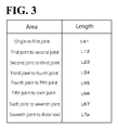
- FIG. 3 shows an exemplary area length table.
- the area length table shows the lengths of all the arm sections ranging from the origin of the robot coordinate system to the distal end of the probe 6. These arm sections are delimited by the joints 31 to 37, and the lengths between adjacent pairs of the joints 31 to 37 respectively correspond to the lengths of the links 41 to 46.
- the area length table is used to calculate a position coordinate of the distal end of the probe 6.
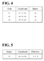
- FIG. 4 shows an exemplary hole coordinate table.
- the hole coordinate table shows the positions of the holes 8a in the robot coordinate system in the case where the robot 2 is correctly positioned relative to the work stand 8.
- the position of the hole 8a corresponds to the position of the probe 6 when the probe 6 is fitted with the hole 8a.
- the hole coordinate table also shows the depths of the holes 8a.
- the hole coordinate table is used to calculate the amount of position correction and the amount of direction correction, which are respectively for calculating the position and the reference directions of the work stand 8 relative the robot 2.
- FIG. 5 shows an exemplary origin coordinate table.
- the origin coordinate table shows the position of the origin of the work stand coordinate system in the robot coordinate system.
- the origin coordinate table also shows three-axis reference directions of the work stand coordinate system in the robot coordinate system.
- the origin position and the reference directions of the work stand coordinate system shown in the origin coordinate table are targets of calibration in the calibration processing, and are also used to calculate the target position of the arm 21 in the work processing.
- the controller 10 includes functional sections associated with the calibration processing; namely, a determination section 11, an operation state acquisition section 12, a coordinate calculation section 13, a position correction amount calculation section 14, and a direction correction amount calculation section 15. These functional sections are implemented when the microprocessor of the controller 10 executes the programs stored in the memory.
- the determination section 11 determines whether the probe 6 is fitted with the hole 8a of the work stand 8 based on force that is received by the probe 6 and detected by the force sensor 7. When the determination section 11 determines that the probe 6 is fitted with the hole 8a of the work stand 8, the determination section 11 outputs to the operation state acquisition section 12 a notification indicating that the probe 6 is fitted with the hole 8a. The determination as to whether the probe 6 is fitted with the hole 8a of the work stand 8 will be described in detail later.
- the operation state acquisition section 12 acquires rotation angles of the servomotors 51 to 57 detected by the servomotors 51 to 57, and outputs the acquired rotation angles to the coordinate calculation section 13. That is, the rotation angles of the servomotors 51 to 57 that the operation state acquisition section 12 acquires here indicate states of the joints 31 to 37 of the arm 21 with the probe 6 fitted with the hole 8a of the work stand 8.
- the coordinate calculation section 13 When the coordinate calculation section 13 receives the rotation angles of the servomotors 51 to 57 from the operation state acquisition section 12, the coordinate calculation section 13 calculates a position coordinate of the distal end of the probe 6 based on the rotation angles of the servomotors 51 to 57, and outputs the calculated position coordinate to the position correction amount calculation section 14 and the direction correction amount calculation section 15. Specifically, based on the rotation angles of the servomotors 51 to 57 and the length of each arm section read from the area length table of FIG. 3 , the coordinate calculation section 13 calculates the position coordinate of the distal end of the probe 6 in the robot coordinate system.
- the position correction amount calculation section 14 calculates a position correction amount for correcting the position of the work stand 8 relative to the robot 2 based on the position coordinate of the distal end of the probe 6.
- the calculated position correction amount is the difference between the calculated position coordinate of the distal end of the probe 6 and the position coordinate of a hole 8a read from the hole coordinate table of FIG. 4 .
- the position correction amount thus calculated is used to correct the position of the work stand 8 relative to the robot 2 in the manner shown in FIG. 7 .
- the controller 10 adds the calculated position correction amount to the position coordinate of the origin of the work stand coordinate system in the robot coordinate system that has been read from the origin coordinate table of FIG. 5 , so as to rewrite the content of the origin coordinate table.
- the direction correction amount calculation section 15 calculates a direction correction amount for correcting the reference directions of the work stand 8 relative to the robot 2 based on the position coordinate of the distal end of the probe 6 calculated for each of the plurality of holes 8a. If the position coordinates of the plurality of holes 8a are already known, the position coordinates of the plurality of holes 8a may serve as a basis for defining one or a plurality of directions. For example, if position coordinates of two holes 8a are available, it is possible to define a longitudinal direction of a line segment containing the two holes 8a.
- the direction correction amount is as shown in FIG. 8 ; that is, the direction correction amount may be assumed the difference between a direction defined by the position coordinates of the distal end of the probe 6 calculated for the plurality of holes 8a (calculated direction) and a direction defined by the position coordinates of the plurality of holes 8a read from the hole coordinate table of FIG. 4 (stored direction).
- the stored direction may be stored in the hole coordinate table in advance.
- the direction correction amount thus calculated is used to correct the reference directions of the work stand 8 relative to the robot 2 in the manner shown in FIG. 9 .
- the controller 10 adds the calculated direction correction amount to the reference directions of the work stand coordinate system in the robot coordinate system that have been read from the origin coordinate table of FIG. 5 , so as to rewrite the content of the origin coordinate table.
- the above-described calibration processing ensures calibration of the origin position and the reference directions of the work stand coordinate system in the robot coordinate system. This, as a result, eliminates or minimizes displacement of the target position of the arm 21 calculated by the controller 10 in the subsequent work processing relative to the originally intended target position.
- the rewriting of the origin coordinate table should not be construed in a limiting sense.
- Another possible example is to store the calculated position correction amount and the calculated direction correction amount, and apply the position correction amount and the direction correction amount every time the controller 10 calculates the target position of the arm 21 in the robot coordinate system in the work processing.
- the target position of the arm 21 is described using the work stand coordinate system.
- the controller 10 adds a vector from the origin of the robot coordinate system to the origin of the work stand coordinate system to a vector from the origin of the work stand coordinate system to the target position of the arm 21, so as to calculate the target position of the arm 21 in the robot coordinate system. In view of this, it is possible to add vectors of the correction amounts in this calculation process.
- putting the basis of calculating the direction correction amount on the position coordinates of the plurality of holes 8a should not be construed in a limiting sense.
- Another possible example is to put the basis of calculating the direction correction amount on structure shape information such as a boring direction of the holes 8a stored in the hole coordinate table in advance, and on posture information of the probe 6 calculated based on the rotation angles of the servomotors 51 to 57.
- the extending direction of the probe 6 fitted with the hole 8a corresponds to the boring direction of the hole 8a.
- the calculated direction correction amount may be assumed the difference between the extending direction of the probe 6 calculated based on the rotation angles of the servomotors 51 to 57 and the boring direction of the hole 8a read from the hole coordinate table.
- This embodiment eliminates the need for using a visual sensor in calculating the position correction amount for correcting the position of the work stand 8 relative to the robot 2 and in calculating the direction correction amount for correcting the reference directions of the work stand 8 relative to the robot 2.
- Using a visual sensor for position calibration and direction calibration may degrade the calibration accuracy due to the influence of the illumination environment and luster of objects in a visual range.
- this embodiment eliminates or minimizes such influence and ensures accurate calibration.
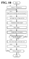
- FIG. 10 is a flowchart illustrating the contact control according to the first embodiment
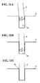
- FIGs. 11A to 11C schematically illustrate the contact control according to the first embodiment.
- the controller 10 drives the servomotors 51 to 57 to fit the probe 6 with the holes 8a of the work stand 8.
- the controller 10 moves the probe 6 to its initial position. For example, the controller 10 moves the probe 6 toward the position coordinate of a hole 8a read from the hole coordinate table of FIG. 4 , and brings the probe 6 into proximity to the hole 8a.
- the probe 6 is not completely fitted with the hole 8a as shown in, for example, FIG. 11A .
- the controller 10 determines a target position and a target posture of the probe 6 for bringing the probe 6 into proximity to the hole 8a, and also determines rotation angles of the servomotors 51 to 57 that implement the target position and the target posture.
- the controller 10 selects an optimum combination based on an inverse kinetics algorithm.
- an exemplary combination to be selected is a combination that has less of a load on the joints 31 to 37.
- the operation of bringing the probe 6 into proximity to the hole 8a may be a manual operation.
- the controller 10 selects one provisional displacement direction from among a plurality of provisional displacement directions, and sets a target value of micro-displacement in the selected provisional displacement direction.
- the plurality of provisional displacement directions include various directions such as translational directions and rotational directions.
- Each of the provisional displacement directions preferably contains a component of the insertion direction of the probe 6 into the hole 8a.
- the insertion direction recognized by the controller 10 is similar to, if not exactly the same as, the actual insertion direction. This ensures setting of a provisional displacement direction containing a component of the insertion direction.
- examples of the plurality of provisional displacement directions are indicated by dashed-line arrows.
- step S 14 the controller 10 determines rotation angles of the servomotors 51 to 57 for implementing the target value of micro-displacement that has been set. At this step as well, the controller 10 selects an optimum combination from among the plurality of combinations of the rotation angles of the servomotors 51 to 57 based on an inverse kinetics algorithm.
- the controller 10 drives the servomotors 51 to 57 to implement the determined rotation angles of the servomotors 51 to 57. This provides the probe 6 with motive power in the provisional displacement direction, bringing the probe 6 into proximity to the target value of micro-displacement.
- step S16 from a detection signal of the force sensor 7, the controller 10 acquires force information indicating force received by the probe 6 when the probe 6 is provided with the motive power in the provisional displacement direction, and the controller 10 stores the force information in the memory.
- the controller 10 performs the above-described processing at steps S12 to S16 for all the provisional displacement directions (S 17).
- the controller 10 proceeds the processing to step S18.
- the controller 10 selects one provisional displacement direction from among the plurality of provisional displacement directions as a displacement direction based on the force information stored in the memory. For example, the provisional displacement direction in which the probe 6 receives the smallest force is selected as the displacement direction. In FIGs. 11A and 11B , examples of the selected displacement direction are indicated by solid-line arrows.
- the controller 10 drives the servomotors 51 to 57 to displace the probe 6 in the selected displacement direction.
- the controller 10 may store the rotation angles of the servomotors 51 to 57 determined at step S 14 and use the rotation angles, or the controller 10 may determine rotation angles of the servomotors 51 to 57 anew.
- the amount of displacement of the probe 6 may be equal to or larger than the above-described micro-displacement. It is also possible to displace the probe 6 in the selected displacement direction until the force received by the probe 6 becomes equal to or larger than a predetermined value.
- the displacement direction is determined after the processing at steps S12 to S16 has been completed for all the provisional displacement directions.
- the force received by the probe 6 provided with the motive power in the provisional displacement direction is equal to or smaller than the predetermined value, it is possible to determine the displacement direction before completion of the processing at steps S12 to S16 for all the provisional displacement directions.
- step S20 the controller 10 determines whether the probe 6 is fitted with a hole 8a of the work stand 8 (which is a function as the determination section 11).
- the controller 10 determines that the probe 6 is not fitted with the hole 8a of the work stand 8 (S20: NO)
- the controller 10 repeats the processing at steps S12 to S19.
- FIG. 11C shows a state in which the probe 6 is fitted with the hole 8a of the work stand 8.
- the controller 10 determines that the probe 6 is fitted with the hole 8a of the work stand 8 when, for example, motive power in the plurality of provisional displacement directions is applied to the probe 6 in approximately the same manner as the processing at steps S12 to S 17 and when the force received by the probe 6 here is equal to or larger than the predetermined value in any of the provisional displacement directions.
- fitting determination is to provide a device that detects the insertion amount of the probe 6 and to compare the insertion amount of the probe 6 thus detected with the depth of the hole 8a stored in the hole coordinate table of FIG. 4 .
- the rotation angles of the servomotors 51 to 57 are determined based on an inverse kinetics algorithm. Specifically, exemplary rotation angles of the servomotors 51 to 57 to be selected throughout the time until the probe 6 is fitted with the hole 8a of the work stand 8 are those rotation angles that have less of a load on the joints 31 to 37. This ensures accurate calculation of the position coordinate of the distal end of the probe 6 in the calibration processing.
- FIG. 12 illustrates an exemplary configuration of the distal end of the arm 21 and jigs 83 of the work stand 8.
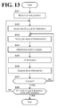
- FIG. 13 is a flowchart illustrating the contact control according to the second embodiment, and
- FIG. 14 schematically illustrates the contact control according to the second embodiment.
- a plurality of L-shaped jigs 83 are disposed on a surface 81 of the work stand 8.
- Each of the L-shaped jigs 83 has two inner surfaces 832 and 833, which intersect the surface 81 of the work stand 8 and define a recessed portion 8b.
- the jigs 83, which are disposed on the surface 81 of the work stand 8, are examples of the structure disposed on the work stand 8.
- the probe 6 and a hand 69 are disposed side by side on the distal end of the arm 21, and the probe 6 includes a spherical distal end portion 61.
- a direction orthogonal to the surface 81 of the work stand 8 will be assumed a Z direction
- directions orthogonal to the two surfaces 832 and 833 of the jig 83 will be assumed an X direction and a Y direction.
- the X, Y, and Z directions recognized by the controller 10 may not be exactly the same as actual X, Y, and Z directions. Even though a slight tolerance occurs, the contact control described below is not particularly affected.
- the controller 10 drives the servomotors 51 to 57 to move the probe 6 while maintaining its posture. Specifically, the controller 10 determines the target position of the probe 6 so as to bring the probe 6 into proximity to the jig 83 of the work stand 8. At the same time, while maintaining the target posture of the probe 6, the controller 10 calculates the rotation angles of the servomotors 51 to 57 to implement the target position and the target posture. For example, in this embodiment, the controller 10 maintains the posture of the probe 6 to keep the extending direction of the probe 6 along the Z direction.
- the controller 10 moves the probe 6 to its initial position.
- the controller 10 moves the probe 6 toward a position coordinate of the jig 83 stored in advance to bring the probe 6 into proximity to the jig 83.
- the distal end portion 61 of the probe 6 is on the side of the recessed portion 8b of the jig 83 at the time when the probe 6 is moved to its initial position.
- the controller 10 determines the target position of the probe 6 to bring the probe 6 into proximity to the jig 83. At the same time, while maintaining the target posture of the probe 6, the controller 10 determines the rotation angles of the servomotors 51 to 57 to implement the target position and the target posture.
- the arm 21 of the robot 2 has seven degrees of freedom. Among the seven degrees of freedom, three degrees of rotational freedom are used to maintain the posture of the probe 6, and the rest of the degrees of freedom include one redundant degree of freedom in addition to three degrees of translational freedom.
- there are a plurality of combinations of the rotation angles of the servomotors 51 to 57 that can implement the target position and the target posture. From among the plurality of combinations of the rotation angles of the servomotors 51 to 57, the controller 10 selects an optimum combination based on an inverse kinetics algorithm to which a limitation condition to maintain the target posture of the probe 6 is added.
- the operation of bringing the probe 6 into proximity to the jig 83 may be a manual operation.
- the controller 10 selects one direction from among the X, Y, and Z directions.
- the controller 10 sets a target value of the amount of displacement of the probe 6 in the selected direction, determines rotation angles of the servomotors 51 to 57 to implement the set target value of the displacement amount, and drives the servomotors 51 to 57.
- the controller 10 selects an optimum combination based on an inverse kinetics algorithm to which a limitation condition to maintain the target posture of the probe 6 is added.
- the probe 6 is displaced in the selected direction in the maintained posture.
- the controller 10 acquires force information indicating force received by the probe 6 when the probe 6 is displaced in the selected direction. Thus, the controller 10 determines whether the distal end portion 61 of the probe 6 is in contact state. Specifically, when the force received by the probe 6 is equal to or larger than a predetermined value, the controller 10 determines that the distal end portion 61 of the probe 6 is in contact state.
- controller 10 determines that the distal end portion 61 of the probe 6 is not in contact state (S27: NO)
- the controller 10 repeats the processing at steps S23 to S26.
- the controller 10 determines that the distal end portion 61 of the probe 6 is in contact state (S27: YES)
- the controller 10 performs the processing at steps S22 to S27 for the other directions (S28: NO).
- the controller 10 determines that the distal end portion 61 of the probe 6 is in contact state for all the X, Y, and Z directions (S28: YES), the controller 10 ends the contact control and proceeds to the above-described calibration processing.
- the distal end portion 61 of the probe 6 is in contact with all of the two inner surfaces 832 and 833 of the L-shaped jig 83 and the surface 81 of the work stand 8.
- the controller 10 acquires the rotation angles of the servomotors 51 to 57 at the time when the distal end portion 61 of the probe 6 is in contact state. Then, the controller 10 calculates a position coordinate of the distal end portion 61 of the probe 6, and calculates a position correction amount based on the difference between the calculated position coordinate of the distal end portion 61 of the probe 6 and the position coordinate of the jig 83 stored in advance.
- the controller 10 further includes a contact control unit 16 as shown in, for example, FIG. 15 . Also the contact control unit 16 and the determinator 11 implement the above-described contact control.
- FIG. 10 is a flowchart illustrating the contact control according to the third embodiment
- FIGs. 11A to 11C schematically illustrate the contact control according to the third embodiment.
- the contact control unit 16 drives the servomotors 51 to 57 to fit the probe 6 with the holes 8a of the work stand 8.
- the contact control unit 16 moves the probe 6 to its initial position. For example, the contact control unit 16 moves the probe 6 toward the position coordinate of a hole 8a read from the hole coordinate table of FIG. 4 , and brings the probe 6 into proximity to the hole 8a.
- the probe 6 is not completely fitted with the hole 8a as shown in, for example, FIG. 11A .
- the contact control unit 16 determines a target position and a target posture of the probe 6 for bringing the probe 6 into proximity to the hole 8a, and also determines rotation angles of the servomotors 51 to 57 that implement the target position and the target posture.
- the arm 21 of the robot 2 has a redundant degree of freedom, there are a plurality of combinations of the rotation angles of the servomotors 51 to 57 that can implement the target position and the target posture. From among the plurality of combinations of the rotation angles of the servomotors 51 to 57, the contact control unit 16 selects an optimum combination based on an inverse kinetics algorithm.
- an exemplary combination to be selected is a combination that has less of a load on the joints 31 to 37.
- the operation of bringing the probe 6 into proximity to the hole 8a may be a manual operation.
- the contact control unit 16 selects one provisional displacement direction from among a plurality of provisional displacement directions, and sets a target value of micro-displacement in the selected provisional displacement direction.
- the plurality of provisional displacement directions include various directions such as translational directions and rotational directions.
- Each of the provisional displacement directions preferably contains a component of the insertion direction of the probe 6 into the hole 8a.
- the insertion direction recognized by the contact control unit 16 is similar to, if not exactly the same as, the actual insertion direction. This ensures setting of a provisional displacement direction containing a component of the insertion direction.
- examples of the plurality of provisional displacement directions are indicated by dashed-line arrows.
- the contact control unit 16 determines rotation angles of the servomotors 51 to 57 for implementing the target value of micro-displacement that has been set. At this step as well, the contact control unit 16 selects an optimum combination from among the plurality of combinations of the rotation angles of the servomotors 51 to 57 based on an inverse kinetics algorithm.
- the contact control unit 16 drives the servomotors 51 to 57 to implement the determined rotation angles of the servomotors 51 to 57. This provides the probe 6 with motive power in the provisional displacement direction, bringing the probe 6 into proximity to the target value of micro-displacement.
- the contact control unit 16 acquires force information indicating force received by the probe 6 when the probe 6 is provided with the motive power in the provisional displacement direction, and the contact control unit 16 stores the force information in the memory.
- the contact control unit 16 performs the above-described processing at steps S12 to S16 for all the provisional displacement directions (S17).
- the contact control unit 16 proceeds the processing to step S18.
- the contact control unit 16 selects one provisional displacement direction from among the plurality of provisional displacement directions as a displacement direction based on the force information stored in the memory. For example, the provisional displacement direction in which the probe 6 receives the smallest force is selected as the displacement direction. In FIGs. 11A and 11B , examples of the selected displacement direction are indicated by solid-line arrows.
- the contact control unit 16 drives the servomotors 51 to 57 to displace the probe 6 in the selected displacement direction.
- the contact control unit 16 may store the rotation angles of the servomotors 51 to 57 determined at step S14 and use the rotation angles, or the contact control unit 16 may determine rotation angles of the servomotors 51 to 57 anew.
- the amount of displacement of the probe 6 may be equal to or larger than the above-described micro-displacement. It is also possible to displace the probe 6 in the selected displacement direction until the force received by the probe 6 becomes equal to or larger than a predetermined value.
- the contact control unit 16 may notify the determinator 11 of finishing the step S19 (i.e. driving the servomotors 51 to 57). In this case, when the determinator 11 receives the notification (i.e. finishing the step S19 by the contact control unit 16), the determinator 11 may begin to implement the following step S20.
- the displacement direction is determined after the processing at steps S12 to S16 has been completed for all the provisional displacement directions.
- the force received by the probe 6 provided with the motive power in the provisional displacement direction is equal to or smaller than the predetermined value, it is possible to determine the displacement direction before completion of the processing at steps S12 to S16 for all the provisional displacement directions.
- the determinator 11 determines whether the probe 6 is fitted with a hole 8a of the work stand 8.
- the determinator 11 determines that the probe 6 is not fitted with the hole 8a of the work stand 8 (S20: NO)
- the determinator 11 commands the contact control unit 16 to repeat the processing at steps S12 to S19.
- FIG. 11C shows a state in which the probe 6 is fitted with the hole 8a of the work stand 8.
- the determinator 11 determines that the probe 6 is fitted with the hole 8a of the work stand 8 when, for example, motive power in the plurality of provisional displacement directions is applied to the probe 6 in approximately the same manner as the processing at steps S12 to S 17 and when the force received by the probe 6 here is equal to or larger than the predetermined value in any of the provisional displacement directions.
- fitting determination is to provide a device that detects the insertion amount of the probe 6 and to compare the insertion amount of the probe 6 thus detected with the depth of the hole 8a stored in the hole coordinate table of FIG. 4 .
- the rotation angles of the servomotors 51 to 57 are determined based on an inverse kinetics algorithm. Specifically, exemplary rotation angles of the servomotors 51 to 57 to be selected throughout the time until the probe 6 is fitted with the hole 8a of the work stand 8 are those rotation angles that have less of a load on the joints 31 to 37. This ensures accurate calculation of the position coordinate of the distal end of the probe 6 in the calibration processing.
- FIG. 12 illustrates an exemplary configuration of the distal end of the arm 21 and jigs 83 of the work stand 8.
- FIG. 13 is a flowchart illustrating the contact control according to the fourth embodiment, and
- FIG. 14 schematically illustrates the contact control according to the fourth embodiment.
- a plurality of L-shaped jigs 83 are disposed on a surface 81 of the work stand 8.
- Each of the L-shaped jigs 83 has two inner surfaces 832 and 833, which intersect the surface 81 of the work stand 8 and define a recessed portion 8b.
- the jigs 83, which are disposed on the surface 81 of the work stand 8, are examples of the structure disposed on the work stand 8.
- the probe 6 and a hand 69 are disposed side by side on the distal end of the arm 21, and the probe 6 includes a spherical distal end portion 61.
- a direction orthogonal to the surface 81 of the work stand 8 will be assumed a Z direction
- directions orthogonal to the two surfaces 832 and 833 of the jig 83 will be assumed an X direction and a Y direction.
- the contact control unit 16 drives the servomotors 51 to 57 to move the probe 6 while maintaining its posture. Specifically, the contact control unit 16 determines the target position of the probe 6 so as to bring the probe 6 into proximity to the jig 83 of the work stand 8. At the same time, while maintaining the target posture of the probe 6, the contact control unit 16 calculates the rotation angles of the servomotors 51 to 57 to implement the target position and the target posture. For example, in this embodiment, the contact control unit 16 maintains the posture of the probe 6 to keep the extending direction of the probe 6 along the Z direction.
- the contact control unit 16 moves the probe 6 to its initial position.
- the contact control unit 16 moves the probe 6 toward a position coordinate of the jig 83 stored in advance to bring the probe 6 into proximity to the jig 83.
- the distal end portion 61 of the probe 6 is on the side of the recessed portion 8b of the jig 83 at the time when the probe 6 is moved to its initial position.
- the contact control unit 16 determines the target position of the probe 6 to bring the probe 6 into proximity to the jig 83. At the same time, while maintaining the target posture of the probe 6, the contact control unit 16 determines the rotation angles of the servomotors 51 to 57 to implement the target position and the target posture.
- the arm 21 of the robot 2 has seven degrees of freedom. Among the seven degrees of freedom, three degrees of rotational freedom are used to maintain the posture of the probe 6, and the rest of the degrees of freedom include one redundant degree of freedom in addition to three degrees of translational freedom.
- there are a plurality of combinations of the rotation angles of the servomotors 51 to 57 that can implement the target position and the target posture. From among the plurality of combinations of the rotation angles of the servomotors 51 to 57, the contact control unit 16 selects an optimum combination based on an inverse kinetics algorithm to which a limitation condition to maintain the target posture of the probe 6 is added.
- the operation of bringing the probe 6 into proximity to the jig 83 may be a manual operation.
- the contact control unit 16 selects one direction from among the X, Y, and Z directions.
- the contact control unit 16 sets a target value of the amount of displacement of the probe 6 in the selected direction, determines rotation angles of the servomotors 51 to 57 to implement the set target value of the displacement amount, and drives the servomotors 51 to 57.
- the contact control unit 16 selects an optimum combination based on an inverse kinetics algorithm to which a limitation condition to maintain the target posture of the probe 6 is added. Thus, the probe 6 is displaced in the selected direction in the maintained posture.
- the determinator 11 acquires force information indicating force received by the probe 6 when the probe 6 is displaced in the selected direction. Thus, the determinator 11 determines whether the distal end portion 61 of the probe 6 is in contact state. Specifically, when the force received by the probe 6 is equal to or larger than a predetermined value, the determinator 11 determines that the distal end portion 61 of the probe 6 is in contact state.
- the determinator 11 determines that the distal end portion 61 of the probe 6 is not in contact state (S27: NO)
- the determinator 11 commands the contact control unit 16 to repeat the processing at steps S23 to S26.
- the determinator 11 determines that the distal end portion 61 of the probe 6 is in contact state (S27: YES)
- the determinator 11 commands the contact control unit 16 to perform the processing at steps S22 to S27 for the other directions (S28: NO).
- the determinator 11 determines that the distal end portion 61 of the probe 6 is in contact state for all the X, Y, and Z directions (S28: YES)
- the determinator 11 commands the contact control unit 16 to end the contact control and proceeds to the above-described calibration processing.
- the distal end portion 61 of the probe 6 is in contact with all of the two inner surfaces 832 and 833 of the L-shaped jig 83 and the surface 81 of the work stand 8.
- the operation state acquisitor 12 acquires the rotation angles of the servomotors 51 to 57 at the time when the distal end portion 61 of the probe 6 is in contact state. Then, the coordinate calculator 13 calculates a position coordinate of the distal end portion 61 of the probe 6, and the position correction amount calculator 14 calculates a position correction amount based on the difference between the calculated position coordinate of the distal end portion 61 of the probe 6 and the position coordinate of the jig 83 stored in advance.
- the contact control unit 16 included in the controller 10 should not be construed in a limiting sense. Another possible example is that the contact control unit 16 may be separate from the controller 10. Also the contact control unit 16 may be tangible (for example, in the form of device, apparatus and/or electrical circuit) or intangible (for example, in the form of program and/or software).
Landscapes
- Engineering & Computer Science (AREA)
- Robotics (AREA)
- Mechanical Engineering (AREA)
- Physics & Mathematics (AREA)
- General Physics & Mathematics (AREA)
- Manipulator (AREA)
- Numerical Control (AREA)
Abstract
Description
- The present invention relates to a robot system, a robot control apparatus, and a method for controlling a robot.
- Japanese Unexamined Patent Application Publication
11-123682 - The contents of Japanese Unexamined Patent Application Publication
11-123682 - Unfortunately, in the above technique, the visual sensor, which cannot be used while the robot is working, is provided for the only purpose of detecting the position at which the automated guided vehicle is stopped.
- The present invention has been made in view of the above-described circumstances, and it is an object of the present invention to provide a robot system, a robot control apparatus, and a method for controlling a robot that ensure correction of the position of a work stand relative to a robot without using a visual sensor.
- According to one aspect of the present disclosure, a robot system includes a robot and a controller. The robot includes an arm, a plurality of actuators, a plurality of sensors, a probe, and a force sensor. The arm includes a plurality of joints. The plurality of actuators are configured to drive the plurality of joints. The plurality of sensors are configured to detect operation states of the plurality of actuators. The probe is mounted on the arm. The force sensor is configured to detect force received by the probe. The controller is configured to control the robot, and includes a determination section, an operation state acquisition section, a coordinate calculation section, and a position correction amount calculation section. The determination section is configured to determine whether the force received by the probe from a structure disposed at a predetermined position on a work stand satisfies a predetermined condition. The operation state acquisition section is configured to acquire the operation states of the plurality of actuators when the force received by the probe satisfies the predetermined condition. The coordinate calculation section is configured to calculate a position coordinate of the probe based on the operation states of the plurality of actuators. The position correction amount calculation section is configured to calculate a correction amount of a position of the work stand relative to the robot based on the position coordinate of the probe.
- In the one aspect of the present disclosure, the structure on the work stand may include a plurality of structures.
- In the one aspect of the present disclosure, the controller may further include a direction correction amount calculation section configured to calculate a correction amount of the work stand in a reference direction relative to the robot based on the position coordinate of the probe calculated for each of the plurality of structures.
- In the one aspect of the present disclosure, the determination section may be configured to determine whether the probe is in contact with the structure in a predetermined posture.
- In the one aspect of the present disclosure, the probe and the structure may have shapes that are fittable with each other. The determination section may be configured to determine whether the probe and the structure are fitted with each other.
- In the one aspect of the present disclosure, the robot system may further include a contact control unit configured to control the plurality of actuators to bring the probe into contact with the structure. Based on force received by the probe when motive power in a plurality of directions is applied to the probe, the contact control unit may be configured to select one direction among the plurality of directions as a displacement direction of the probe.
- In the one aspect of the present disclosure, the contact control unit may be configured to determine operation states of the plurality of actuators based on an inverse kinetics algorithm when the motive power in the plurality of directions is applied to the probe.
- In the one aspect of the present disclosure, the structure may include three surfaces intersecting to each other to define a recessed portion. The determination section may be configured to determine whether the probe is in contact with the three surfaces.
- In the one aspect of the present disclosure, the robot system may further include a contact control unit configured to control the plurality of actuators to bring the probe into contact with the structure. The contact control unit may be configured to displace the probe while keeping the probe in a predetermined posture.
- In the one aspect of the present disclosure, the contact control unit may be configured to determine the operation states of the plurality of actuators based on an inverse kinetics algorithm to which a limitation condition to keep the probe in the predetermined posture is added.
- According to another aspect of the present disclosure, a robot control apparatus is configured to control a robot. The robot includes an arm, a plurality of actuators, a plurality of sensors, a probe, and a force sensor. The arm includes a plurality of joints. The plurality of actuators are configured to drive the plurality of joints. The plurality of sensors are configured to detect operation states of the plurality of actuators. The probe is mounted on the arm. The force sensor is configured to detect force received by the probe. The robot control apparatus includes a determination section, an operation state acquisition section, a coordinate calculation section, and a position correction amount calculation section. The determination section is configured to determine whether the force received by the probe from a structure disposed at a predetermined position on a work stand satisfies a predetermined condition. The operation state acquisition section is configured to acquire the operation states of the plurality of actuators when the force received by the probe satisfies the predetermined condition. The coordinate calculation section is configured to calculate a position coordinate of the probe based on the operation states of the plurality of actuators. The position correction amount calculation section is configured to calculate a correction amount of a position of the work stand relative to the robot based on the position coordinate of the probe.
- In the another aspect of the present disclosure, the structure on the work stand may include a plurality of structures.
- In the another aspect of the present disclosure, the robot control apparatus may further include a direction correction amount calculation section configured to calculate a correction amount of the work stand in a reference direction relative to the robot based on the position coordinate of the probe calculated for each of the plurality of structures.
- In the another aspect of the present disclosure, the determination section may be configured to determine whether the probe is in contact with the structure in a predetermined posture.
- In the another aspect of the present disclosure, the probe and the structure may have shapes that are fittable with each other. The determination section may be configured to determine whether the probe and the structure are fitted with each other.
- In the another aspect of the present disclosure, the robot control apparatus may further include a contact control unit configured to control the plurality of actuators to bring the probe into contact with the structure. Based on force received by the probe when motive power in a plurality of directions is applied to the probe, the contact control unit may be configured to select one direction among the plurality of directions as a displacement direction of the probe.
- In the another aspect of the present disclosure, the contact control unit may be configured to determine operation states of the plurality of actuators based on an inverse kinetics algorithm when the motive power in the plurality of directions is applied to the probe.
- In the another aspect of the present disclosure, the structure may include three surfaces intersecting to each other to define a recessed portion. The determination section may be configured to determine whether the probe is in contact with the three surfaces.
- In the another aspect of the present disclosure, the robot control apparatus may further include a contact control unit configured to control the plurality of actuators to bring the probe into contact with the structure. The contact control unit may be configured to displace the probe while keeping the probe in a predetermined posture.
- In the another aspect of the present disclosure, the contact control unit may be configured to determine the operation states of the plurality of actuators based on an inverse kinetics algorithm to which a limitation condition to keep the probe in the predetermined posture is added.
- In the another aspect of the present disclosure, a robot system includes the robot control apparatus.
- In the another aspect of the present disclosure, the robot system may further include the robot.
- According to the other aspect of the present disclosure, a method is for controlling a robot for controlling a robot. The robot includes an arm, a plurality of actuators, a plurality of sensors, a probe, and a force sensor. The arm includes a plurality of joints. The plurality of actuators are configured to drive the plurality of joints. The plurality of sensors are configured to detect operation states of the plurality of actuators. The probe is mounted on the arm. The force sensor is configured to detect force received by the probe. The method includes determining whether the force received by the probe from a structure disposed at a predetermined position on a work stand satisfies a predetermined condition. The operation states of the plurality of actuators are acquired when the force received by the probe satisfies the predetermined condition. A position coordinate of the probe is calculated based on the operation states of the plurality of actuators. A correction amount of a position of the work stand relative to the robot is calculated based on the position coordinate of the probe.
- The aspects of the present disclosure ensure correction of the position of the work stand relative to the robot without using a visual sensor.
- A more complete appreciation of the present disclosure and many of the attendant advantages thereof will be readily obtained as the same becomes better understood by reference to the following detailed description when considered in connection with the accompanying drawings, wherein:
-
FIG. 1 is a schematic view of a robot system according to an embodiment; -
FIG. 2 is a block diagram illustrating an exemplary configuration of the robot system; -
FIG. 3 shows an exemplary area length table; -
FIG. 4 shows an exemplary hole coordinate table; -
FIG. 5 shows an exemplary origin coordinate table; -
FIG. 6 is a diagram illustrating an example of how to calculate a position correction amount; -
FIG. 7 is a diagram illustrating an example of how to apply the position correction amount; -
FIG. 8 is a diagram illustrating an example of how to calculate a direction correction amount; -
FIG. 9 is a diagram illustrating an example of how to apply the direction correction amount; -
FIG. 10 is a flowchart illustrating contact control according to a first embodiment; -
FIGs. 11A to 11C schematically illustrate the contact control according to the first embodiment; -
FIG. 12 schematically illustrates an exemplary configuration of a distal end of an arm and jigs on a work stand; -
FIG. 13 is a flowchart illustrating contact control according to a second embodiment; -
FIG. 14 schematically illustrates the contact control according to the second embodiment; and -
FIG. 15 is a block diagram illustrating an exemplary configuration of the robot system in a third embodiment and a fourth embodiment. - The embodiments will now be described with reference to the accompanying drawings, wherein like reference numerals designate corresponding or identical elements throughout the various drawings.
-
FIG. 1 is a schematic view of arobot system 1 according to an embodiment.FIG. 2 is a block diagram illustrating an exemplary configuration of therobot system 1. - The
robot system 1 includes arobot 2 and acontroller 10. Therobot 2 includes an articulatedarm 21. Thecontroller 10 controls therobot 2. Thecontroller 10 is an example of the robot control apparatus. Therobot 2 is disposed on acarriage 9, and movable relative to awork stand 8 and positioned relative to thework stand 8. Thecontroller 10 is accommodated in thecarriage 9. Thearm 21 of therobot 2 will not be limited to one arm but may have two or more arms. - The
arm 21 of therobot 2 includes a plurality ofrotatable joints 31 to 37, and a plurality oflinks 41 to 47 coupled to each other through thejoints 31 to 37. Each of thejoints 31 to 37 is rotatable in directions indicated by the two-headed arrows shown inFIG. 1 . Each of thejoints 31 to 37 has a rotation axis that is orthogonal to the rotation axis of an adjacent joint. In this embodiment, thearm 21 of therobot 2 includes sevenjoints 31 to 37, which provide seven degrees of freedom. Specifically, thearm 21 of therobot 2 includes one redundant degree of freedom in addition to six degrees of freedom, which are necessary for making changes in position and posture (three degrees of translational freedom and three degrees of rotational freedom). It should be noted that the number of joints of thearm 21 may be six. - The
robot 2 includes a plurality ofservomotors 51 to 57 to drive thejoints 31 to 37 into rotation. Theservomotors 51 to 57 drive thejoints 31 to 37 into rotation in response to a command from thecontroller 10. Theservomotors 51 to 57 include encoders to detect a rotation angle and output a detection signal that corresponds to the rotation angle. Theservomotors 51 to 57 are examples of the actuators to drive the joints. The encoders are examples of the sensors to detect operation states of the actuators. The rotation angles of theservomotors 51 to 57 are examples of the operation states of the actuators. - A rod-shaped
probe 6 is disposed on the distal end of thearm 21 of therobot 2. Aforce sensor 7 is disposed between the distal end of thearm 21 and theprobe 6. Theforce sensor 7 detects force received by theprobe 6, and outputs to the controller 10 a detection signal that corresponds to the received force. An example of theforce sensor 7 is a six-axis force sensor to detect force in three translational directions and in three rotational directions. Other examples of theforce sensor 7 than the rod-shapedprobe 6 include end effectors such as a hand. - A plurality of
holes 8a are formed at a plurality of predetermined positions on asurface 81 of thework stand 8. Theholes 8a and theprobe 6 are fittable with each other. The portions of thework stand 8 in which theholes 8a are formed are examples of the structure disposed on thework stand 8. In this embodiment, theprobe 6 is a columnar rod having a circular cross-section, and thehole 8a is a bottomed hole having a circular cross-section. The shape of theprobe 6 and the shape of thehole 8a are not particularly limited insofar as theprobe 6 and thehole 8a are fittable with each other. When theprobe 6 is fitted with thehole 8a, theprobe 6 has its posture accord with the shape of thehole 8a to enable theprobe 6 to contact the inner surface of thehole 8a. For example, when theprobe 6 is fitted with thehole 8a, a gap of approximately 10 µm is formed between the outer surface of theprobe 6 and the inner surface of thehole 8a. - The
controller 10 includes a microprocessor and a memory. The memory stores programs to be executed by the microprocessor and data used for control. The programs may be provided from an information recording medium readable by a computer or may be provided through a communication line. Thecontroller 10 performs various types of processing in accordance with the programs read from the memory. - For example, the
controller 10 performs such work processing as to subject an object to a predetermined kind of work such as mounting of parts. In the work processing, thecontroller 10 drives theservomotors 51 to 57 based on data indicating operation content, thus enabling thearm 21 of therobot 2 to perform the predetermined work. In the data indicating the operation content, the target position of thearm 21 is described using a work stand coordinate system, which is based on thework stand 8, instead of using a robot coordinate system, which is based on therobot 2. Thus, thecontroller 10 stores the position of the origin of the work stand coordinate system in the robot coordinate system, and uses the position of the origin to calculate the target position of thearm 21 in the robot coordinate system. - Furthermore, during the time between installation of the
robot 2 and the above-described work processing, thecontroller 10 performs calibration processing described below. When the installedrobot 2 is displaced from a predetermined position and a predetermined posture, the target position of thearm 21 calculated by thecontroller 10 in the above-described work processing may be displaced from an originally intended target position. This is addressed by thecontroller 10 performing the calibration processing prior to the work processing. The calibration processing performed by thecontroller 10 will be described in detail below. - The tables in
FIGs. 3 to 5 show exemplary data stored in the memory of thecontroller 10 in association with the calibration processing. -
FIG. 3 shows an exemplary area length table. The area length table shows the lengths of all the arm sections ranging from the origin of the robot coordinate system to the distal end of theprobe 6. These arm sections are delimited by thejoints 31 to 37, and the lengths between adjacent pairs of thejoints 31 to 37 respectively correspond to the lengths of thelinks 41 to 46. The area length table is used to calculate a position coordinate of the distal end of theprobe 6. -
FIG. 4 shows an exemplary hole coordinate table. The hole coordinate table shows the positions of theholes 8a in the robot coordinate system in the case where therobot 2 is correctly positioned relative to thework stand 8. The position of thehole 8a corresponds to the position of theprobe 6 when theprobe 6 is fitted with thehole 8a. The hole coordinate table also shows the depths of theholes 8a. The hole coordinate table is used to calculate the amount of position correction and the amount of direction correction, which are respectively for calculating the position and the reference directions of thework stand 8 relative therobot 2. -
FIG. 5 shows an exemplary origin coordinate table. The origin coordinate table shows the position of the origin of the work stand coordinate system in the robot coordinate system. The origin coordinate table also shows three-axis reference directions of the work stand coordinate system in the robot coordinate system. The origin position and the reference directions of the work stand coordinate system shown in the origin coordinate table are targets of calibration in the calibration processing, and are also used to calculate the target position of thearm 21 in the work processing. - Referring back to
FIG. 2 , thecontroller 10 includes functional sections associated with the calibration processing; namely, adetermination section 11, an operationstate acquisition section 12, a coordinatecalculation section 13, a position correctionamount calculation section 14, and a direction correctionamount calculation section 15. These functional sections are implemented when the microprocessor of thecontroller 10 executes the programs stored in the memory. - The following description concerns processing after the
probe 6 has been fitted with thehole 8a of thework stand 8. Then, processing prior to theprobe 6 being fitted with thehole 8a of the work stand 8 (processing as a contact control unit) will be described in detail later. - The
determination section 11 determines whether theprobe 6 is fitted with thehole 8a of thework stand 8 based on force that is received by theprobe 6 and detected by theforce sensor 7. When thedetermination section 11 determines that theprobe 6 is fitted with thehole 8a of thework stand 8, thedetermination section 11 outputs to the operation state acquisition section 12 a notification indicating that theprobe 6 is fitted with thehole 8a. The determination as to whether theprobe 6 is fitted with thehole 8a of thework stand 8 will be described in detail later. - When the
determination section 11 notifies the operationstate acquisition section 12 of the fitting of theprobe 6 with thehole 8a of thework stand 8, the operationstate acquisition section 12 acquires rotation angles of theservomotors 51 to 57 detected by theservomotors 51 to 57, and outputs the acquired rotation angles to the coordinatecalculation section 13. That is, the rotation angles of theservomotors 51 to 57 that the operationstate acquisition section 12 acquires here indicate states of thejoints 31 to 37 of thearm 21 with theprobe 6 fitted with thehole 8a of thework stand 8. - When the coordinate
calculation section 13 receives the rotation angles of theservomotors 51 to 57 from the operationstate acquisition section 12, the coordinatecalculation section 13 calculates a position coordinate of the distal end of theprobe 6 based on the rotation angles of theservomotors 51 to 57, and outputs the calculated position coordinate to the position correctionamount calculation section 14 and the direction correctionamount calculation section 15. Specifically, based on the rotation angles of theservomotors 51 to 57 and the length of each arm section read from the area length table ofFIG. 3 , the coordinatecalculation section 13 calculates the position coordinate of the distal end of theprobe 6 in the robot coordinate system. - When the position correction
amount calculation section 14 receives the position coordinate of the distal end of theprobe 6 from the coordinatecalculation section 13, the position correctionamount calculation section 14 calculates a position correction amount for correcting the position of thework stand 8 relative to therobot 2 based on the position coordinate of the distal end of theprobe 6. Specifically, as shown inFIG. 6 , the calculated position correction amount is the difference between the calculated position coordinate of the distal end of theprobe 6 and the position coordinate of ahole 8a read from the hole coordinate table ofFIG. 4 . - The position correction amount thus calculated is used to correct the position of the
work stand 8 relative to therobot 2 in the manner shown inFIG. 7 . For example, thecontroller 10 adds the calculated position correction amount to the position coordinate of the origin of the work stand coordinate system in the robot coordinate system that has been read from the origin coordinate table ofFIG. 5 , so as to rewrite the content of the origin coordinate table. - When the direction correction
amount calculation section 15 receives the position coordinate of the distal end of theprobe 6 from the coordinatecalculation section 13, the direction correctionamount calculation section 15 calculates a direction correction amount for correcting the reference directions of thework stand 8 relative to therobot 2 based on the position coordinate of the distal end of theprobe 6 calculated for each of the plurality ofholes 8a. If the position coordinates of the plurality ofholes 8a are already known, the position coordinates of the plurality ofholes 8a may serve as a basis for defining one or a plurality of directions. For example, if position coordinates of twoholes 8a are available, it is possible to define a longitudinal direction of a line segment containing the twoholes 8a. If position coordinates of threeholes 8a are available, it is possible to define a normal direction of a plane containing the threeholes 8a. In view of this, the direction correction amount is as shown inFIG. 8 ; that is, the direction correction amount may be assumed the difference between a direction defined by the position coordinates of the distal end of theprobe 6 calculated for the plurality ofholes 8a (calculated direction) and a direction defined by the position coordinates of the plurality ofholes 8a read from the hole coordinate table ofFIG. 4 (stored direction). The stored direction may be stored in the hole coordinate table in advance. - The direction correction amount thus calculated is used to correct the reference directions of the
work stand 8 relative to therobot 2 in the manner shown inFIG. 9 . For example, thecontroller 10 adds the calculated direction correction amount to the reference directions of the work stand coordinate system in the robot coordinate system that have been read from the origin coordinate table ofFIG. 5 , so as to rewrite the content of the origin coordinate table. - The above-described calibration processing ensures calibration of the origin position and the reference directions of the work stand coordinate system in the robot coordinate system. This, as a result, eliminates or minimizes displacement of the target position of the
arm 21 calculated by thecontroller 10 in the subsequent work processing relative to the originally intended target position. - The rewriting of the origin coordinate table should not be construed in a limiting sense. Another possible example is to store the calculated position correction amount and the calculated direction correction amount, and apply the position correction amount and the direction correction amount every time the
controller 10 calculates the target position of thearm 21 in the robot coordinate system in the work processing. Specifically, in the data indicating the operation content, the target position of thearm 21 is described using the work stand coordinate system. Thecontroller 10 adds a vector from the origin of the robot coordinate system to the origin of the work stand coordinate system to a vector from the origin of the work stand coordinate system to the target position of thearm 21, so as to calculate the target position of thearm 21 in the robot coordinate system. In view of this, it is possible to add vectors of the correction amounts in this calculation process. - Furthermore, putting the basis of calculating the direction correction amount on the position coordinates of the plurality of
holes 8a should not be construed in a limiting sense. Another possible example is to put the basis of calculating the direction correction amount on structure shape information such as a boring direction of theholes 8a stored in the hole coordinate table in advance, and on posture information of theprobe 6 calculated based on the rotation angles of theservomotors 51 to 57. Specifically, the extending direction of theprobe 6 fitted with thehole 8a corresponds to the boring direction of thehole 8a. Thus, the calculated direction correction amount may be assumed the difference between the extending direction of theprobe 6 calculated based on the rotation angles of theservomotors 51 to 57 and the boring direction of thehole 8a read from the hole coordinate table. - This embodiment eliminates the need for using a visual sensor in calculating the position correction amount for correcting the position of the
work stand 8 relative to therobot 2 and in calculating the direction correction amount for correcting the reference directions of thework stand 8 relative to therobot 2. Using a visual sensor for position calibration and direction calibration may degrade the calibration accuracy due to the influence of the illumination environment and luster of objects in a visual range. In contrast, this embodiment eliminates or minimizes such influence and ensures accurate calibration. - Description will be made with regard to a first embodiment of the contact control of fitting the
probe 6 with theholes 8a of thework stand 8.FIG. 10 is a flowchart illustrating the contact control according to the first embodiment, andFIGs. 11A to 11C schematically illustrate the contact control according to the first embodiment. In this contact control, thecontroller 10 drives theservomotors 51 to 57 to fit theprobe 6 with theholes 8a of thework stand 8. - At step S11, the
controller 10 moves theprobe 6 to its initial position. For example, thecontroller 10 moves theprobe 6 toward the position coordinate of ahole 8a read from the hole coordinate table ofFIG. 4 , and brings theprobe 6 into proximity to thehole 8a. When the installedrobot 2 is displaced from a predetermined position and a predetermined posture, theprobe 6 is not completely fitted with thehole 8a as shown in, for example,FIG. 11A . - More specifically, the
controller 10 determines a target position and a target posture of theprobe 6 for bringing theprobe 6 into proximity to thehole 8a, and also determines rotation angles of theservomotors 51 to 57 that implement the target position and the target posture. Incidentally, since thearm 21 of therobot 2 has a redundant degree of freedom, there are a plurality of combinations of the rotation angles of theservomotors 51 to 57 that can implement the target position and the target posture. From among the plurality of combinations of the rotation angles of theservomotors 51 to 57, thecontroller 10 selects an optimum combination based on an inverse kinetics algorithm. Here, an exemplary combination to be selected is a combination that has less of a load on thejoints 31 to 37. - The operation of bringing the
probe 6 into proximity to thehole 8a may be a manual operation. - At steps S12 and
S 13, thecontroller 10 selects one provisional displacement direction from among a plurality of provisional displacement directions, and sets a target value of micro-displacement in the selected provisional displacement direction. The plurality of provisional displacement directions include various directions such as translational directions and rotational directions. Each of the provisional displacement directions preferably contains a component of the insertion direction of theprobe 6 into thehole 8a. Here, the insertion direction recognized by thecontroller 10 is similar to, if not exactly the same as, the actual insertion direction. This ensures setting of a provisional displacement direction containing a component of the insertion direction. InFIGs. 11A and 11B , examples of the plurality of provisional displacement directions are indicated by dashed-line arrows. - At
step S 14, thecontroller 10 determines rotation angles of theservomotors 51 to 57 for implementing the target value of micro-displacement that has been set. At this step as well, thecontroller 10 selects an optimum combination from among the plurality of combinations of the rotation angles of theservomotors 51 to 57 based on an inverse kinetics algorithm. - At step S15, the
controller 10 drives theservomotors 51 to 57 to implement the determined rotation angles of theservomotors 51 to 57. This provides theprobe 6 with motive power in the provisional displacement direction, bringing theprobe 6 into proximity to the target value of micro-displacement. - At step S16, from a detection signal of the
force sensor 7, thecontroller 10 acquires force information indicating force received by theprobe 6 when theprobe 6 is provided with the motive power in the provisional displacement direction, and thecontroller 10 stores the force information in the memory. - The
controller 10 performs the above-described processing at steps S12 to S16 for all the provisional displacement directions (S 17). When the processing for all the provisional displacement directions is completed (S17: YES), thecontroller 10 proceeds the processing to step S18. - At step S18, the
controller 10 selects one provisional displacement direction from among the plurality of provisional displacement directions as a displacement direction based on the force information stored in the memory. For example, the provisional displacement direction in which theprobe 6 receives the smallest force is selected as the displacement direction. InFIGs. 11A and 11B , examples of the selected displacement direction are indicated by solid-line arrows. - At step S19, the
controller 10 drives theservomotors 51 to 57 to displace theprobe 6 in the selected displacement direction. Here, thecontroller 10 may store the rotation angles of theservomotors 51 to 57 determined at step S 14 and use the rotation angles, or thecontroller 10 may determine rotation angles of theservomotors 51 to 57 anew. The amount of displacement of theprobe 6 may be equal to or larger than the above-described micro-displacement. It is also possible to displace theprobe 6 in the selected displacement direction until the force received by theprobe 6 becomes equal to or larger than a predetermined value. - In the embodiment shown in
FIG. 10 , the displacement direction is determined after the processing at steps S12 to S16 has been completed for all the provisional displacement directions. When the force received by theprobe 6 provided with the motive power in the provisional displacement direction is equal to or smaller than the predetermined value, it is possible to determine the displacement direction before completion of the processing at steps S12 to S16 for all the provisional displacement directions. - At step S20, the
controller 10 determines whether theprobe 6 is fitted with ahole 8a of the work stand 8 (which is a function as the determination section 11). When thecontroller 10 determines that theprobe 6 is not fitted with thehole 8a of the work stand 8 (S20: NO), thecontroller 10 repeats the processing at steps S12 to S19. - When the
controller 10 determines that theprobe 6 is fitted with thehole 8a of the work stand 8 (S20: YES), thecontroller 10 ends the contact control and proceeds to the above-described calibration processing.FIG. 11C shows a state in which theprobe 6 is fitted with thehole 8a of thework stand 8. Thecontroller 10 determines that theprobe 6 is fitted with thehole 8a of thework stand 8 when, for example, motive power in the plurality of provisional displacement directions is applied to theprobe 6 in approximately the same manner as the processing at steps S12 to S 17 and when the force received by theprobe 6 here is equal to or larger than the predetermined value in any of the provisional displacement directions. Reliance solely on the strength of the force received by theprobe 6 in the determination of fitting can cause an erroneous determination if theprobe 6 is stuck in the middle of thehole 8a in the course of fitting. In view of this, another possible example of fitting determination is to provide a device that detects the insertion amount of theprobe 6 and to compare the insertion amount of theprobe 6 thus detected with the depth of thehole 8a stored in the hole coordinate table ofFIG. 4 . - In this embodiment, when the
probe 6 is displaced at steps S11 and S14, the rotation angles of theservomotors 51 to 57 are determined based on an inverse kinetics algorithm. Specifically, exemplary rotation angles of theservomotors 51 to 57 to be selected throughout the time until theprobe 6 is fitted with thehole 8a of thework stand 8 are those rotation angles that have less of a load on thejoints 31 to 37. This ensures accurate calculation of the position coordinate of the distal end of theprobe 6 in the calibration processing. - Contact control according to a second embodiment will be described below.
FIG. 12 illustrates an exemplary configuration of the distal end of thearm 21 andjigs 83 of thework stand 8.FIG. 13 is a flowchart illustrating the contact control according to the second embodiment, andFIG. 14 schematically illustrates the contact control according to the second embodiment. - As shown in
FIG. 12 , in this embodiment, a plurality of L-shapedjigs 83 are disposed on asurface 81 of thework stand 8. Each of the L-shapedjigs 83 has twoinner surfaces surface 81 of thework stand 8 and define a recessedportion 8b. Thejigs 83, which are disposed on thesurface 81 of thework stand 8, are examples of the structure disposed on thework stand 8. In this embodiment, theprobe 6 and ahand 69 are disposed side by side on the distal end of thearm 21, and theprobe 6 includes a sphericaldistal end portion 61. - In this embodiment, a direction orthogonal to the
surface 81 of thework stand 8 will be assumed a Z direction, and directions orthogonal to the twosurfaces jig 83 will be assumed an X direction and a Y direction. When the installedrobot 2 is displaced from a predetermined posture, the X, Y, and Z directions recognized by thecontroller 10 may not be exactly the same as actual X, Y, and Z directions. Even though a slight tolerance occurs, the contact control described below is not particularly affected. - In this embodiment, the
controller 10 drives theservomotors 51 to 57 to move theprobe 6 while maintaining its posture. Specifically, thecontroller 10 determines the target position of theprobe 6 so as to bring theprobe 6 into proximity to thejig 83 of thework stand 8. At the same time, while maintaining the target posture of theprobe 6, thecontroller 10 calculates the rotation angles of theservomotors 51 to 57 to implement the target position and the target posture. For example, in this embodiment, thecontroller 10 maintains the posture of theprobe 6 to keep the extending direction of theprobe 6 along the Z direction. - At step S21, the
controller 10 moves theprobe 6 to its initial position. For example, thecontroller 10 moves theprobe 6 toward a position coordinate of thejig 83 stored in advance to bring theprobe 6 into proximity to thejig 83. Here, assume that thedistal end portion 61 of theprobe 6 is on the side of the recessedportion 8b of thejig 83 at the time when theprobe 6 is moved to its initial position. - More specifically, the
controller 10 determines the target position of theprobe 6 to bring theprobe 6 into proximity to thejig 83. At the same time, while maintaining the target posture of theprobe 6, thecontroller 10 determines the rotation angles of theservomotors 51 to 57 to implement the target position and the target posture. Incidentally, thearm 21 of therobot 2 has seven degrees of freedom. Among the seven degrees of freedom, three degrees of rotational freedom are used to maintain the posture of theprobe 6, and the rest of the degrees of freedom include one redundant degree of freedom in addition to three degrees of translational freedom. Hence, there are a plurality of combinations of the rotation angles of theservomotors 51 to 57 that can implement the target position and the target posture. From among the plurality of combinations of the rotation angles of theservomotors 51 to 57, thecontroller 10 selects an optimum combination based on an inverse kinetics algorithm to which a limitation condition to maintain the target posture of theprobe 6 is added. - The operation of bringing the
probe 6 into proximity to thejig 83 may be a manual operation. - At step S22, the
controller 10 selects one direction from among the X, Y, and Z directions. - At steps S23, S24, and S25, the
controller 10 sets a target value of the amount of displacement of theprobe 6 in the selected direction, determines rotation angles of theservomotors 51 to 57 to implement the set target value of the displacement amount, and drives theservomotors 51 to 57. At this stage as well, from among the plurality of combinations of the rotation angles of theservomotors 51 to 57, thecontroller 10 selects an optimum combination based on an inverse kinetics algorithm to which a limitation condition to maintain the target posture of theprobe 6 is added. Thus, theprobe 6 is displaced in the selected direction in the maintained posture. - At steps S26 and S27, from a detection signal of the
force sensor 7, thecontroller 10 acquires force information indicating force received by theprobe 6 when theprobe 6 is displaced in the selected direction. Thus, thecontroller 10 determines whether thedistal end portion 61 of theprobe 6 is in contact state. Specifically, when the force received by theprobe 6 is equal to or larger than a predetermined value, thecontroller 10 determines that thedistal end portion 61 of theprobe 6 is in contact state. - When the
controller 10 determines that thedistal end portion 61 of theprobe 6 is not in contact state (S27: NO), thecontroller 10 repeats the processing at steps S23 to S26. - When the
controller 10 determines that thedistal end portion 61 of theprobe 6 is in contact state (S27: YES), thecontroller 10 performs the processing at steps S22 to S27 for the other directions (S28: NO). - When the
controller 10 determines that thedistal end portion 61 of theprobe 6 is in contact state for all the X, Y, and Z directions (S28: YES), thecontroller 10 ends the contact control and proceeds to the above-described calibration processing. Here, as shown inFIG. 14 , thedistal end portion 61 of theprobe 6 is in contact with all of the twoinner surfaces jig 83 and thesurface 81 of thework stand 8. - In the calibration processing, for all the X, Y, and Z directions, the
controller 10 acquires the rotation angles of theservomotors 51 to 57 at the time when thedistal end portion 61 of theprobe 6 is in contact state. Then, thecontroller 10 calculates a position coordinate of thedistal end portion 61 of theprobe 6, and calculates a position correction amount based on the difference between the calculated position coordinate of thedistal end portion 61 of theprobe 6 and the position coordinate of thejig 83 stored in advance. - In a third embodiment and a fourth embodiment, the
controller 10 further includes acontact control unit 16 as shown in, for example,FIG. 15 . Also thecontact control unit 16 and thedeterminator 11 implement the above-described contact control. - Description will be made with regard to a third embodiment of the contact control of fitting the
probe 6 with theholes 8a of thework stand 8.FIG. 10 is a flowchart illustrating the contact control according to the third embodiment, andFIGs. 11A to 11C schematically illustrate the contact control according to the third embodiment. In this contact control, thecontact control unit 16 drives theservomotors 51 to 57 to fit theprobe 6 with theholes 8a of thework stand 8. - At step S11, the
contact control unit 16 moves theprobe 6 to its initial position. For example, thecontact control unit 16 moves theprobe 6 toward the position coordinate of ahole 8a read from the hole coordinate table ofFIG. 4 , and brings theprobe 6 into proximity to thehole 8a. When the installedrobot 2 is displaced from a predetermined position and a predetermined posture, theprobe 6 is not completely fitted with thehole 8a as shown in, for example,FIG. 11A . - More specifically, the
contact control unit 16 determines a target position and a target posture of theprobe 6 for bringing theprobe 6 into proximity to thehole 8a, and also determines rotation angles of theservomotors 51 to 57 that implement the target position and the target posture. Incidentally, since thearm 21 of therobot 2 has a redundant degree of freedom, there are a plurality of combinations of the rotation angles of theservomotors 51 to 57 that can implement the target position and the target posture. From among the plurality of combinations of the rotation angles of theservomotors 51 to 57, thecontact control unit 16 selects an optimum combination based on an inverse kinetics algorithm. Here, an exemplary combination to be selected is a combination that has less of a load on thejoints 31 to 37. - The operation of bringing the
probe 6 into proximity to thehole 8a may be a manual operation. - At steps S12 and S13, the
contact control unit 16 selects one provisional displacement direction from among a plurality of provisional displacement directions, and sets a target value of micro-displacement in the selected provisional displacement direction. The plurality of provisional displacement directions include various directions such as translational directions and rotational directions. Each of the provisional displacement directions preferably contains a component of the insertion direction of theprobe 6 into thehole 8a. Here, the insertion direction recognized by thecontact control unit 16 is similar to, if not exactly the same as, the actual insertion direction. This ensures setting of a provisional displacement direction containing a component of the insertion direction. InFIGs. 11A and 11B , examples of the plurality of provisional displacement directions are indicated by dashed-line arrows. - At
step S 14, thecontact control unit 16 determines rotation angles of theservomotors 51 to 57 for implementing the target value of micro-displacement that has been set. At this step as well, thecontact control unit 16 selects an optimum combination from among the plurality of combinations of the rotation angles of theservomotors 51 to 57 based on an inverse kinetics algorithm. - At step S15, the
contact control unit 16 drives theservomotors 51 to 57 to implement the determined rotation angles of theservomotors 51 to 57. This provides theprobe 6 with motive power in the provisional displacement direction, bringing theprobe 6 into proximity to the target value of micro-displacement. - At step S16, from a detection signal of the
force sensor 7, thecontact control unit 16 acquires force information indicating force received by theprobe 6 when theprobe 6 is provided with the motive power in the provisional displacement direction, and thecontact control unit 16 stores the force information in the memory. - The
contact control unit 16 performs the above-described processing at steps S12 to S16 for all the provisional displacement directions (S17). When the processing for all the provisional displacement directions is completed (S17: YES), thecontact control unit 16 proceeds the processing to step S18. - At step S18, the
contact control unit 16 selects one provisional displacement direction from among the plurality of provisional displacement directions as a displacement direction based on the force information stored in the memory. For example, the provisional displacement direction in which theprobe 6 receives the smallest force is selected as the displacement direction. InFIGs. 11A and 11B , examples of the selected displacement direction are indicated by solid-line arrows. - At step S19, the
contact control unit 16 drives theservomotors 51 to 57 to displace theprobe 6 in the selected displacement direction. Here, thecontact control unit 16 may store the rotation angles of theservomotors 51 to 57 determined at step S14 and use the rotation angles, or thecontact control unit 16 may determine rotation angles of theservomotors 51 to 57 anew. The amount of displacement of theprobe 6 may be equal to or larger than the above-described micro-displacement. It is also possible to displace theprobe 6 in the selected displacement direction until the force received by theprobe 6 becomes equal to or larger than a predetermined value. When thecontact control unit 16 has finished the step S19 (i.e. driving theservomotors 51 to 57), thecontact control unit 16 may notify thedeterminator 11 of finishing the step S19 (i.e. driving theservomotors 51 to 57). In this case, when thedeterminator 11 receives the notification (i.e. finishing the step S19 by the contact control unit 16), thedeterminator 11 may begin to implement the following step S20. - In the embodiment shown in
FIG. 10 , the displacement direction is determined after the processing at steps S12 to S16 has been completed for all the provisional displacement directions. When the force received by theprobe 6 provided with the motive power in the provisional displacement direction is equal to or smaller than the predetermined value, it is possible to determine the displacement direction before completion of the processing at steps S12 to S16 for all the provisional displacement directions. - At step S20, the
determinator 11 determines whether theprobe 6 is fitted with ahole 8a of thework stand 8. When thedeterminator 11 determines that theprobe 6 is not fitted with thehole 8a of the work stand 8 (S20: NO), thedeterminator 11 commands thecontact control unit 16 to repeat the processing at steps S12 to S19. - When the
determinator 11 determines that theprobe 6 is fitted with thehole 8a of the work stand 8 (S20: YES), thedeterminator 11 commands thecontact control unit 16 to end the contact control. Then, thedeterminator 11 proceeds to the above-described calibration processing.FIG. 11C shows a state in which theprobe 6 is fitted with thehole 8a of thework stand 8. Thedeterminator 11 determines that theprobe 6 is fitted with thehole 8a of thework stand 8 when, for example, motive power in the plurality of provisional displacement directions is applied to theprobe 6 in approximately the same manner as the processing at steps S12 to S 17 and when the force received by theprobe 6 here is equal to or larger than the predetermined value in any of the provisional displacement directions. Reliance solely on the strength of the force received by theprobe 6 in the determination of fitting can cause an erroneous determination if theprobe 6 is stuck in the middle of thehole 8a in the course of fitting. In view of this, another possible example of fitting determination is to provide a device that detects the insertion amount of theprobe 6 and to compare the insertion amount of theprobe 6 thus detected with the depth of thehole 8a stored in the hole coordinate table ofFIG. 4 . - In this embodiment, when the
probe 6 is displaced at steps S11 and S14, the rotation angles of theservomotors 51 to 57 are determined based on an inverse kinetics algorithm. Specifically, exemplary rotation angles of theservomotors 51 to 57 to be selected throughout the time until theprobe 6 is fitted with thehole 8a of thework stand 8 are those rotation angles that have less of a load on thejoints 31 to 37. This ensures accurate calculation of the position coordinate of the distal end of theprobe 6 in the calibration processing. - Contact control according to the fourth embodiment will be described below.
FIG. 12 illustrates an exemplary configuration of the distal end of thearm 21 andjigs 83 of thework stand 8.FIG. 13 is a flowchart illustrating the contact control according to the fourth embodiment, andFIG. 14 schematically illustrates the contact control according to the fourth embodiment. - As shown in
FIG. 12 , in this embodiment, a plurality of L-shapedjigs 83 are disposed on asurface 81 of thework stand 8. Each of the L-shapedjigs 83 has twoinner surfaces surface 81 of thework stand 8 and define a recessedportion 8b. Thejigs 83, which are disposed on thesurface 81 of thework stand 8, are examples of the structure disposed on thework stand 8. In this embodiment, theprobe 6 and ahand 69 are disposed side by side on the distal end of thearm 21, and theprobe 6 includes a sphericaldistal end portion 61. - In this embodiment, a direction orthogonal to the
surface 81 of thework stand 8 will be assumed a Z direction, and directions orthogonal to the twosurfaces jig 83 will be assumed an X direction and a Y direction. When the installedrobot 2 is displaced from a predetermined posture, the X, Y, and Z directions recognized by thecontact control unit 16 may not be exactly the same as actual X, Y, and Z directions. Even though a slight tolerance occurs, the contact control described below is not particularly affected. - In this embodiment, the
contact control unit 16 drives theservomotors 51 to 57 to move theprobe 6 while maintaining its posture. Specifically, thecontact control unit 16 determines the target position of theprobe 6 so as to bring theprobe 6 into proximity to thejig 83 of thework stand 8. At the same time, while maintaining the target posture of theprobe 6, thecontact control unit 16 calculates the rotation angles of theservomotors 51 to 57 to implement the target position and the target posture. For example, in this embodiment, thecontact control unit 16 maintains the posture of theprobe 6 to keep the extending direction of theprobe 6 along the Z direction. - At step S21, the
contact control unit 16 moves theprobe 6 to its initial position. For example, thecontact control unit 16 moves theprobe 6 toward a position coordinate of thejig 83 stored in advance to bring theprobe 6 into proximity to thejig 83. Here, assume that thedistal end portion 61 of theprobe 6 is on the side of the recessedportion 8b of thejig 83 at the time when theprobe 6 is moved to its initial position. - More specifically, the
contact control unit 16 determines the target position of theprobe 6 to bring theprobe 6 into proximity to thejig 83. At the same time, while maintaining the target posture of theprobe 6, thecontact control unit 16 determines the rotation angles of theservomotors 51 to 57 to implement the target position and the target posture. Incidentally, thearm 21 of therobot 2 has seven degrees of freedom. Among the seven degrees of freedom, three degrees of rotational freedom are used to maintain the posture of theprobe 6, and the rest of the degrees of freedom include one redundant degree of freedom in addition to three degrees of translational freedom. Hence, there are a plurality of combinations of the rotation angles of theservomotors 51 to 57 that can implement the target position and the target posture. From among the plurality of combinations of the rotation angles of theservomotors 51 to 57, thecontact control unit 16 selects an optimum combination based on an inverse kinetics algorithm to which a limitation condition to maintain the target posture of theprobe 6 is added. - The operation of bringing the
probe 6 into proximity to thejig 83 may be a manual operation. - At step S22, the
contact control unit 16 selects one direction from among the X, Y, and Z directions. - At steps S23, S24, and S25, the
contact control unit 16 sets a target value of the amount of displacement of theprobe 6 in the selected direction, determines rotation angles of theservomotors 51 to 57 to implement the set target value of the displacement amount, and drives theservomotors 51 to 57. At this stage as well, from among the plurality of combinations of the rotation angles of theservomotors 51 to 57, thecontact control unit 16 selects an optimum combination based on an inverse kinetics algorithm to which a limitation condition to maintain the target posture of theprobe 6 is added. Thus, theprobe 6 is displaced in the selected direction in the maintained posture. - At steps S26 and S27, from a detection signal of the
force sensor 7, thedeterminator 11 acquires force information indicating force received by theprobe 6 when theprobe 6 is displaced in the selected direction. Thus, thedeterminator 11 determines whether thedistal end portion 61 of theprobe 6 is in contact state. Specifically, when the force received by theprobe 6 is equal to or larger than a predetermined value, thedeterminator 11 determines that thedistal end portion 61 of theprobe 6 is in contact state. - When the
determinator 11 determines that thedistal end portion 61 of theprobe 6 is not in contact state (S27: NO), thedeterminator 11 commands thecontact control unit 16 to repeat the processing at steps S23 to S26. - When the
determinator 11 determines that thedistal end portion 61 of theprobe 6 is in contact state (S27: YES), thedeterminator 11 commands thecontact control unit 16 to perform the processing at steps S22 to S27 for the other directions (S28: NO). - When the
determinator 11 determines that thedistal end portion 61 of theprobe 6 is in contact state for all the X, Y, and Z directions (S28: YES), thedeterminator 11 commands thecontact control unit 16 to end the contact control and proceeds to the above-described calibration processing. Here, as shown inFIG. 14 , thedistal end portion 61 of theprobe 6 is in contact with all of the twoinner surfaces jig 83 and thesurface 81 of thework stand 8. - In the calibration processing, for all the X, Y, and Z directions, the operation state acquisitor 12 acquires the rotation angles of the
servomotors 51 to 57 at the time when thedistal end portion 61 of theprobe 6 is in contact state. Then, the coordinatecalculator 13 calculates a position coordinate of thedistal end portion 61 of theprobe 6, and the positioncorrection amount calculator 14 calculates a position correction amount based on the difference between the calculated position coordinate of thedistal end portion 61 of theprobe 6 and the position coordinate of thejig 83 stored in advance. - Regarding the above-described third embodiment and fourth embodiment, the
contact control unit 16 included in thecontroller 10 should not be construed in a limiting sense. Another possible example is that thecontact control unit 16 may be separate from thecontroller 10. Also thecontact control unit 16 may be tangible (for example, in the form of device, apparatus and/or electrical circuit) or intangible (for example, in the form of program and/or software). - Obviously, numerous modifications and variations of the present disclosure are possible in light of the above teachings. It is therefore to be understood that within the scope of the appended claims, the present disclosure may be practiced otherwise than as specifically described herein.
- 1
- Robot system
- 2
- Robot
- 21
- Arm
- 31 to 37
- Joint
- 41 to 47
- Link
- 51 to 57
- Servomotor (example of the actuator)
- 6
- Probe
- 61
- Distal end portion
- 69
- Hand
- 7
- Force sensor
- 8
- Work stand
- 8a
- Hole
- 8b
- Recessed portion
- 81
- Surface
- 83
- Jig
- 832, 833
- Surface
- 9
- Carriage
- 10
- Controller (example of the robot control apparatus)
- 11
- Determination section
- 12
- Operation state acquisition section
- 13
- Coordinate calculation section
- 14
- Position correction amount calculation section
- 15
- Direction correction amount calculation section
Claims (12)
- A robot system (1), characterized by:a robot (2) comprising:an arm (21) comprising a plurality of joints (31) to (37);a plurality of actuators (51) to (57) configured to drive the plurality of joints (31) to (37);a plurality of sensors configured to detect operation states of the plurality of actuators (51) to (57);a probe (6) mounted on the arm (21); anda force sensor (7) configured to detect force received by the probe (6); anda controller (10) configured to control the robot (2), the controller (10) comprising:a determination section (11) configured to determine whether the force received by the probe (6) from a structure disposed at a predetermined position on a work stand (8) satisfies a predetermined condition;an operation state acquisition section (12) configured to acquire the operation states of the plurality of actuators (51) to (57) when the force received by the probe (6) satisfies the predetermined condition;a coordinate calculation section (13) configured to calculate a position coordinate of the probe (6) based on the operation states of the plurality of actuators (51) to (57); anda position correction amount calculation section (14) configured to calculate a correction amount of a position of the work stand (8) relative to the robot (2) based on the position coordinate of the probe (6).
- The robot system (1) according to claim 1, wherein the structure on the work stand (8) comprises a plurality of structures.
- The robot system (1) according to claim 2, wherein the controller (10) further comprises a direction correction amount calculation section (15) configured to calculate a correction amount of the work stand (8) in a reference direction relative to the robot (2) based on the position coordinate of the probe (6) calculated for each of the plurality of structures.
- The robot system (1) according to claim 1, wherein the determination section (11) is configured to determine whether the probe (6) is in contact with the structure in a predetermined posture.
- The robot system (1) according to claim 1,
wherein the probe (6) and the structure have shapes that are fittable with each other, and
wherein the determination section (11) is configured to determine whether the probe (6) and the structure are fitted with each other. - The robot system (1) according to claim 5, further comprising a contact control unit configured to control the plurality of actuators (51) to (57) to bring the probe (6) into contact with the structure, wherein based on force received by the probe (6) when motive power in a plurality of directions is applied to the probe (6), the contact control unit is configured to select one direction among the plurality of directions as a displacement direction of the probe (6).
- The robot system (1) according to claim 6, wherein the contact control unit is configured to determine operation states of the plurality of actuators (51) to (57) based on an inverse kinetics algorithm when the motive power in the plurality of directions is applied to the probe (6).
- The robot system (1) according to claim 1,
wherein the structure comprises three surfaces intersecting to each other to define a recessed portion (8b), and
wherein the determination section (11) is configured to determine whether the probe (6) is in contact with the three surfaces. - The robot system (1) according to claim 8, further comprising a contact control unit (16) configured to control the plurality of actuators (51) to (57) to bring the probe (6) into contact with the structure, wherein the contact control unit (16) is configured to displace the probe (6) while keeping the probe (6) in a predetermined posture.
- The robot system (1) according to claim 9, wherein the contact control unit (16) is configured to determine the operation states of the plurality of actuators (51) to (57) based on an inverse kinetics algorithm to which a limitation condition to keep the probe (6) in the predetermined posture is added.
- A robot control apparatus (10) configured to control a robot (2), the robot (2) comprising:an arm (21) comprising a plurality of joints (31) to (37);a plurality of actuators (51) to (57) configured to drive the plurality of joints (31) to (37);a plurality of sensors configured to detect operation states of the plurality of actuators (51) to (57);a probe (6) mounted on the arm (21); anda force sensor (7) configured to detect force received by the probe (6),the robot control apparatus (10) being characterized by:a determination section (11) configured to determine whether the force received by the probe (6) from a structure disposed at a predetermined position on a work stand (8) satisfies a predetermined condition;an operation state acquisition section (12) configured to acquire the operation states of the plurality of actuators (51) to (57) when the force received by the probe (6) satisfies the predetermined condition;a coordinate calculation section (13) configured to calculate a position coordinate of the probe (6) based on the operation states of the plurality of actuators (51) to (57); anda position correction amount calculation section (14) configured to calculate a correction amount of a position of the work stand (8) relative to the robot (2) based on the position coordinate of the probe (6).
- A method for controlling a robot (2), the robot (2) comprising:an arm (21) comprising a plurality of joints (31) to (37);a plurality of actuators (51) to (57) configured to drive the plurality of joints (31) to (37);a plurality of sensors configured to detect operation states of the plurality of actuators (51) to (57);a probe (6) mounted on the arm (21); anda force sensor (7) configured to detect force received by the probe (6),the method being characterized by:determining whether the force received by the probe (6) from a structure disposed at a predetermined position on a work stand (8) satisfies a predetermined condition;acquiring the operation states of the plurality of actuators (51) to (57) when the force received by the probe (6) satisfies the predetermined condition;calculating a position coordinate of the probe (6) based on the operation states of the plurality of actuators (51) to (57); andcalculating a correction amount of a position of the work stand (8) relative to the robot (2) based on the position coordinate of the probe (6).
Applications Claiming Priority (1)
| Application Number | Priority Date | Filing Date | Title |
|---|---|---|---|
| JP2013165923A JP2015033747A (en) | 2013-08-09 | 2013-08-09 | Robot system, robot control apparatus, and robot control method |
Publications (2)
| Publication Number | Publication Date |
|---|---|
| EP2837472A2 true EP2837472A2 (en) | 2015-02-18 |
| EP2837472A3 EP2837472A3 (en) | 2015-04-29 |
Family
ID=51298549
Family Applications (1)
| Application Number | Title | Priority Date | Filing Date |
|---|---|---|---|
| EP20140179260 Withdrawn EP2837472A3 (en) | 2013-08-09 | 2014-07-31 | Robot system, robot control apparatus, method for controlling robot |
Country Status (4)
| Country | Link |
|---|---|
| US (1) | US20150045953A1 (en) |
| EP (1) | EP2837472A3 (en) |
| JP (1) | JP2015033747A (en) |
| CN (1) | CN104339352A (en) |
Cited By (4)
| Publication number | Priority date | Publication date | Assignee | Title |
|---|---|---|---|---|
| EP3067166A1 (en) * | 2015-03-13 | 2016-09-14 | Canon Kabushiki Kaisha | Robot controlling method, robot apparatus, program and recording medium |
| EP3620273A2 (en) * | 2018-09-05 | 2020-03-11 | The Boeing Company | Methods and apparatus for robot control |
| DE102017117928B4 (en) * | 2016-08-10 | 2020-10-01 | Fanuc Corporation | Robot control unit for an assembly robot |
| WO2023227200A1 (en) * | 2022-05-24 | 2023-11-30 | Brainlab Ag | Robotic calibration |
Families Citing this family (25)
| Publication number | Priority date | Publication date | Assignee | Title |
|---|---|---|---|---|
| FR3033635B1 (en) * | 2015-03-10 | 2019-03-29 | Safran Aircraft Engines | THREE-DIMENSIONAL MEASURING MACHINE ROD, IN PARTICULAR OF DIMENSIONS OF AN INTERNAL CAVITY OF A TURBOMACHINE ROTOR |
| JP6521736B2 (en) * | 2015-05-20 | 2019-05-29 | キヤノン株式会社 | Robot apparatus, robot control method, program, recording medium, and method of manufacturing assembly |
| JP6378143B2 (en) * | 2015-07-16 | 2018-08-22 | ファナック株式会社 | Robot teaching apparatus having a guide section for determining the position and posture of an end effector |
| US9815198B2 (en) | 2015-07-23 | 2017-11-14 | X Development Llc | System and method for determining a work offset |
| DE102015219332A1 (en) * | 2015-10-07 | 2017-04-13 | Robert Bosch Gmbh | Sensor device and robot assembly with the sensor device |
| DE102015220066A1 (en) * | 2015-10-15 | 2017-04-20 | Kuka Roboter Gmbh | Haptic referencing of a manipulator |
| CN106945034B (en) * | 2016-01-07 | 2021-09-03 | 鸿富锦精密电子(郑州)有限公司 | Robot point location adjusting method and system |
| JP6555149B2 (en) * | 2016-02-15 | 2019-08-07 | オムロン株式会社 | Arithmetic apparatus, arithmetic method and arithmetic program |
| DE102016004841B4 (en) * | 2016-04-24 | 2018-01-04 | Kastanienbaum GmbH | Method and device for determining a movement sequence for a robot |
| US10583565B2 (en) * | 2016-08-30 | 2020-03-10 | Seiko Epson Corporation | Control apparatus, robot and robot system |
| JP6651636B2 (en) * | 2016-08-30 | 2020-02-19 | 本田技研工業株式会社 | Robot control device and robot control method |
| JP2018126798A (en) * | 2017-02-06 | 2018-08-16 | セイコーエプソン株式会社 | Control device, robot, and robot system |
| JP6457005B2 (en) * | 2017-03-30 | 2019-01-23 | 本田技研工業株式会社 | Position estimation method and gripping method |
| CN107650149B (en) * | 2017-08-21 | 2020-09-18 | 北京精密机电控制设备研究所 | Contact and non-contact fusion measurement system and method based on serial mechanical arm |
| US10919149B2 (en) * | 2017-11-24 | 2021-02-16 | Denso Wave Incorporated | Controller for robot and inverse transforming method for robot |
| KR102543213B1 (en) * | 2018-05-14 | 2023-06-13 | (주)한화 | Method for calibrating coordinate system of robot |
| JP7330876B2 (en) | 2019-12-13 | 2023-08-22 | 川崎重工業株式会社 | POSITION DETECTION METHOD, CONTROL DEVICE AND ROBOT SYSTEM |
| DE112021002551B4 (en) * | 2020-04-27 | 2025-08-14 | Fanuc Corporation | Processes for mastering editing tools |
| IL274911B2 (en) * | 2020-05-25 | 2023-10-01 | Metalix Cad/Cam Ltd | A device and method for calibrating a robotic cell |
| CN113799115B (en) | 2020-06-11 | 2023-03-24 | 台达电子工业股份有限公司 | Coordinate correction method of robot arm |
| CN112363241A (en) * | 2021-01-04 | 2021-02-12 | 中交国通公路工程技术有限公司 | Reinforcing bar position measurement appearance with prevent function of falling |
| EP4043161A1 (en) * | 2021-02-11 | 2022-08-17 | Siemens Aktiengesellschaft | Method for calibrating a robot arm and robot assembly with a robot arm |
| JPWO2023013699A1 (en) * | 2021-08-03 | 2023-02-09 | ||
| US20230075185A1 (en) * | 2021-09-09 | 2023-03-09 | Ford Global Technologies, Llc | Method and system for positioning a moveable robotic system |
| CN118123845B (en) * | 2024-04-30 | 2024-07-16 | 季华实验室 | Space combination robot control method, device, electronic equipment and storage medium |
Citations (1)
| Publication number | Priority date | Publication date | Assignee | Title |
|---|---|---|---|---|
| JPH11123682A (en) | 1997-10-21 | 1999-05-11 | Denso Corp | Stop position detection system for mobile robots |
Family Cites Families (11)
| Publication number | Priority date | Publication date | Assignee | Title |
|---|---|---|---|---|
| JPH04211806A (en) * | 1990-05-17 | 1992-08-03 | Hitachi Ltd | How to estimate the geometrical error of a robot |
| JP3473834B2 (en) * | 1999-11-29 | 2003-12-08 | 株式会社安川電機 | Robot control device |
| SE0001312D0 (en) * | 2000-04-10 | 2000-04-10 | Abb Ab | Industrial robot |
| JP2007136588A (en) * | 2005-11-16 | 2007-06-07 | Yaskawa Electric Corp | Programming pendant |
| JP2008296310A (en) * | 2007-05-30 | 2008-12-11 | Fanuc Ltd | Control device for machining robot |
| US8457790B2 (en) * | 2007-09-14 | 2013-06-04 | Zimmer, Inc. | Robotic calibration method |
| CN101952087B (en) * | 2008-02-06 | 2013-01-16 | 松下电器产业株式会社 | Robot, robot control apparatus, robot control method |
| ATE532610T1 (en) * | 2008-04-30 | 2011-11-15 | Abb Technology Ab | METHOD AND SYSTEM FOR DETERMINING THE RELATIONSHIP BETWEEN A ROBOT COORDINATE SYSTEM AND A LOCAL COORDINATE SYSTEM POSITIONED IN THE ROBOT'S WORKING AREA |
| JP4837113B2 (en) * | 2010-03-18 | 2011-12-14 | ファナック株式会社 | Fitting device using robot |
| JP5321532B2 (en) * | 2010-04-28 | 2013-10-23 | 株式会社安川電機 | Robot calibration apparatus and calibration method |
| JP5218470B2 (en) * | 2010-04-28 | 2013-06-26 | 株式会社安川電機 | Robot work success / failure determination apparatus and method |
-
2013
- 2013-08-09 JP JP2013165923A patent/JP2015033747A/en active Pending
-
2014
- 2014-07-09 CN CN201410325447.6A patent/CN104339352A/en active Pending
- 2014-07-31 EP EP20140179260 patent/EP2837472A3/en not_active Withdrawn
- 2014-08-04 US US14/451,386 patent/US20150045953A1/en not_active Abandoned
Patent Citations (1)
| Publication number | Priority date | Publication date | Assignee | Title |
|---|---|---|---|---|
| JPH11123682A (en) | 1997-10-21 | 1999-05-11 | Denso Corp | Stop position detection system for mobile robots |
Cited By (7)
| Publication number | Priority date | Publication date | Assignee | Title |
|---|---|---|---|---|
| EP3067166A1 (en) * | 2015-03-13 | 2016-09-14 | Canon Kabushiki Kaisha | Robot controlling method, robot apparatus, program and recording medium |
| CN105965505A (en) * | 2015-03-13 | 2016-09-28 | 佳能株式会社 | Robot controlling method, robot apparatus, program and recording medium |
| US10144132B2 (en) | 2015-03-13 | 2018-12-04 | Canon Kabushiki Kaisha | Robot controlling method, robot apparatus, program and recording medium |
| CN105965505B (en) * | 2015-03-13 | 2019-04-05 | 佳能株式会社 | Robot control method, robot device, program and recording medium |
| DE102017117928B4 (en) * | 2016-08-10 | 2020-10-01 | Fanuc Corporation | Robot control unit for an assembly robot |
| EP3620273A2 (en) * | 2018-09-05 | 2020-03-11 | The Boeing Company | Methods and apparatus for robot control |
| WO2023227200A1 (en) * | 2022-05-24 | 2023-11-30 | Brainlab Ag | Robotic calibration |
Also Published As
| Publication number | Publication date |
|---|---|
| JP2015033747A (en) | 2015-02-19 |
| EP2837472A3 (en) | 2015-04-29 |
| US20150045953A1 (en) | 2015-02-12 |
| CN104339352A (en) | 2015-02-11 |
Similar Documents
| Publication | Publication Date | Title |
|---|---|---|
| US20150045953A1 (en) | Robot system, robot control apparatus, method for controlling robot | |
| JP5366018B2 (en) | Robot teaching procedure calibration apparatus and method | |
| JP5321532B2 (en) | Robot calibration apparatus and calibration method | |
| CN110997249B (en) | Work robot and control method of work robot | |
| US8712589B2 (en) | System and method for judging success or failure of work of robot | |
| CN102458779B (en) | Calibration device and method for manipulator | |
| US10618164B2 (en) | Robot system having learning control function and learning control method | |
| US9517560B2 (en) | Robot system and calibration method of the robot system | |
| US20180043540A1 (en) | Robot control unit for assembly robot | |
| JP5786550B2 (en) | 6-axis robot offset detection method | |
| CN108139194B (en) | Sensor device and robot apparatus having the same | |
| US10195744B2 (en) | Control device, robot, and robot system | |
| JP5531996B2 (en) | 6-axis robot offset detection method | |
| US9014853B2 (en) | Calibration method and calibration system for robot | |
| WO2016193686A4 (en) | Characterising robot environments | |
| WO2015030650A4 (en) | Method and system for determination of at least one property of a manipulator | |
| CN112902898A (en) | Three-dimensional measuring device and applicable mechanical arm correction method | |
| JP5672173B2 (en) | 6-axis robot offset detection method | |
| EP2803453A2 (en) | Robot system and method for producing workpiece | |
| JP5447150B2 (en) | Robot control device and method for controlling robot | |
| JP5218540B2 (en) | Assembly robot and its control method | |
| JP2012020348A (en) | Deburring method by robot | |
| JP7172248B2 (en) | Calibration method of force control robot and tool coordinate system | |
| JP2019093504A (en) | Article manufacturing method and robot system | |
| EP3002088A2 (en) | Orthogonal positioning instrument, system and method for automatic machines |
Legal Events
| Date | Code | Title | Description |
|---|---|---|---|
| 17P | Request for examination filed |
Effective date: 20140731 |
|
| AK | Designated contracting states |
Kind code of ref document: A2 Designated state(s): AL AT BE BG CH CY CZ DE DK EE ES FI FR GB GR HR HU IE IS IT LI LT LU LV MC MK MT NL NO PL PT RO RS SE SI SK SM TR |
|
| AX | Request for extension of the european patent |
Extension state: BA ME |
|
| PUAI | Public reference made under article 153(3) epc to a published international application that has entered the european phase |
Free format text: ORIGINAL CODE: 0009012 |
|
| PUAL | Search report despatched |
Free format text: ORIGINAL CODE: 0009013 |
|
| AK | Designated contracting states |
Kind code of ref document: A3 Designated state(s): AL AT BE BG CH CY CZ DE DK EE ES FI FR GB GR HR HU IE IS IT LI LT LU LV MC MK MT NL NO PL PT RO RS SE SI SK SM TR |
|
| AX | Request for extension of the european patent |
Extension state: BA ME |
|
| RIC1 | Information provided on ipc code assigned before grant |
Ipc: B25J 9/16 20060101AFI20150320BHEP |
|
| R17P | Request for examination filed (corrected) |
Effective date: 20151013 |
|
| RBV | Designated contracting states (corrected) |
Designated state(s): AL AT BE BG CH CY CZ DE DK EE ES FI FR GB GR HR HU IE IS IT LI LT LU LV MC MK MT NL NO PL PT RO RS SE SI SK SM TR |
|
| STAA | Information on the status of an ep patent application or granted ep patent |
Free format text: STATUS: THE APPLICATION IS DEEMED TO BE WITHDRAWN |
|
| 18D | Application deemed to be withdrawn |
Effective date: 20170201 |