EP2837470B1 - Staple gun automatically applicable to staples of multiple sorts - Google Patents
Staple gun automatically applicable to staples of multiple sorts Download PDFInfo
- Publication number
- EP2837470B1 EP2837470B1 EP14169098.2A EP14169098A EP2837470B1 EP 2837470 B1 EP2837470 B1 EP 2837470B1 EP 14169098 A EP14169098 A EP 14169098A EP 2837470 B1 EP2837470 B1 EP 2837470B1
- Authority
- EP
- European Patent Office
- Prior art keywords
- staple
- staples
- magazine
- gun
- casing
- Prior art date
- Legal status (The legal status is an assumption and is not a legal conclusion. Google has not performed a legal analysis and makes no representation as to the accuracy of the status listed.)
- Active
Links
Images


Classifications
-
- B—PERFORMING OPERATIONS; TRANSPORTING
- B25—HAND TOOLS; PORTABLE POWER-DRIVEN TOOLS; MANIPULATORS
- B25C—HAND-HELD NAILING OR STAPLING TOOLS; MANUALLY OPERATED PORTABLE STAPLING TOOLS
- B25C5/00—Manually operated portable stapling tools; Hand-held power-operated stapling tools; Staple feeding devices therefor
- B25C5/16—Staple-feeding devices, e.g. with feeding means, supports for staples or accessories concerning feeding devices
- B25C5/1637—Supports for the staples being fed
- B25C5/1641—Supports for the staples being fed allowing the feeding of a variety of elements
- B25C5/1644—Supports for the staples being fed allowing the feeding of a variety of elements of different shapes
- B25C5/1651—Supports for the staples being fed allowing the feeding of a variety of elements of different shapes of T-shaped staples or nails
-
- B—PERFORMING OPERATIONS; TRANSPORTING
- B25—HAND TOOLS; PORTABLE POWER-DRIVEN TOOLS; MANIPULATORS
- B25C—HAND-HELD NAILING OR STAPLING TOOLS; MANUALLY OPERATED PORTABLE STAPLING TOOLS
- B25C5/00—Manually operated portable stapling tools; Hand-held power-operated stapling tools; Staple feeding devices therefor
- B25C5/06—Manually operated portable stapling tools; Hand-held power-operated stapling tools; Staple feeding devices therefor without provision for bending the ends of the staples on to the work
-
- B—PERFORMING OPERATIONS; TRANSPORTING
- B25—HAND TOOLS; PORTABLE POWER-DRIVEN TOOLS; MANIPULATORS
- B25C—HAND-HELD NAILING OR STAPLING TOOLS; MANUALLY OPERATED PORTABLE STAPLING TOOLS
- B25C5/00—Manually operated portable stapling tools; Hand-held power-operated stapling tools; Staple feeding devices therefor
- B25C5/10—Driving means
- B25C5/11—Driving means operated by manual or foot power
-
- B—PERFORMING OPERATIONS; TRANSPORTING
- B25—HAND TOOLS; PORTABLE POWER-DRIVEN TOOLS; MANIPULATORS
- B25C—HAND-HELD NAILING OR STAPLING TOOLS; MANUALLY OPERATED PORTABLE STAPLING TOOLS
- B25C5/00—Manually operated portable stapling tools; Hand-held power-operated stapling tools; Staple feeding devices therefor
- B25C5/16—Staple-feeding devices, e.g. with feeding means, supports for staples or accessories concerning feeding devices
- B25C5/1606—Feeding means
-
- B—PERFORMING OPERATIONS; TRANSPORTING
- B25—HAND TOOLS; PORTABLE POWER-DRIVEN TOOLS; MANIPULATORS
- B25C—HAND-HELD NAILING OR STAPLING TOOLS; MANUALLY OPERATED PORTABLE STAPLING TOOLS
- B25C5/00—Manually operated portable stapling tools; Hand-held power-operated stapling tools; Staple feeding devices therefor
- B25C5/16—Staple-feeding devices, e.g. with feeding means, supports for staples or accessories concerning feeding devices
- B25C5/1637—Supports for the staples being fed
- B25C5/1641—Supports for the staples being fed allowing the feeding of a variety of elements
- B25C5/1658—Supports for the staples being fed allowing the feeding of a variety of elements of different sizes of staples
Definitions
- the present invention relates to staple guns, and more particularly, to a staple gun automatically applicable to staples of multiple sorts.
- the magazine holds T-shaped staples, linearly-shaped staples, U-shaped staples, n-shaped staples, and the like.
- the staple delivery element delivers the staples to a ready-to-eject position below the staple striking element.
- a users uses the arm to drive the staple striking element to strike the staple at the ready-to-eject position such that the staple is ejected downward.
- the user has to tune a controlling element of a conventional staple gun in order to eject the staples one by one rather than two by two from the ready-to-eject position or preclude the situation where the strike performed by the staple striking element on a staple is undesirably restricted to the front half of the staple and thus fails to eject the staple.
- the controlling element is capable of being tuned in a maximum two or three stages; as a result, the staple gun is usually applicable to staples of a maximum two or three thicknesses. Therefore, there is still room for improvement of conventional staple guns in terms of applicability.
- a conventional staple gun is disclosed in WO 2005/102613 A1 .
- Another objective of the present invention is to provide a staple gun which is applicable to staples of multiple specifications and variable thickness and thus has wide application.
- the present invention provides a staple gun automatically applicable to staples of multiple sorts, comprising: a casing having a front blocking surface; a magazine disposed in the casing and adapted to hold a plurality of staples; and a staple delivery element and a resilient element disposed at the magazine.
- the magazine comprises at least a staple cutting portion.
- the staple cutting portion has a top surface, a front end surface, and a guiding surface connected between the top surface and the front end surface.
- the front end surface and the guiding surface of the staple cutting portion face the front blocking surface of the casing.
- a clearance for passing the staples is disposed between the front end surface of the staple cutting portion and the front blocking surface of the casing.
- the staple delivery element pushes the staples in the magazine in a staple delivering direction, such that one of the staples abuts against the front blocking surface of the casing.
- the resilient element enables the staples to push the front end surface and the guiding surface of the staple cutting portion of the magazine, such that the magazine moves relative to the casing in a clearance adjustment direction opposite to the staple delivering direction.
- the breadth of the clearance is designed to allow staples of the least thickness (in comparison with the thicknesses of staples in wide use) to squeeze through the clearance.
- the staple gun of the present invention is also applicable to staples which have large thicknesses and a head portion (such as T-shaped staples, U-shaped staples, and n-shaped staples) because, as soon as the foremost staple is struck, not only does the head portion of the staple slide across the guiding surface of the staple cutting portion of the magazine to reach the front end surface, but the staple cutting portion also advances in the clearance adjustment direction, such that the breadth of the clearance is automatically adjusted in accordance with the thickness of the staple to thereby allow the staple to squeeze through the clearance.
- the staple gun of the present invention is automatically applicable to staples of multiple thicknesses without being tuned by a user. Furthermore, the staple gun of the present invention will work, provided that the thickness of the staples is less than the least distance between the top surface of the staple cutting portion and the front blocking surface of the casing. Accordingly, the staple gun of the present invention has wide application.
- staple gun mentioned in the present invention is not restricted by the way to drive a staple striking element thereof to strike and eject staples. Staple guns driven manually, electrically, pneumatically or in other equivalent ways should fall within the field and the claims of the present invention.
- the casing 20 has therein a magazine 40, a staple delivery element 50, and a resilient element 60 as shown in FIG 3 through FIG. 7 , and a staple striking element 70 (shown in FIG 8 ) driven by the arm 30 to strike and eject staples in a staple striking direction D1.
- the arm 30, the staple striking element 70, and their operation are well known to persons skilled in the art and thus are not describe herein for the sake of brevity.
- the casing 20 comprises a left case element 21, a right case element 22, and a front case element 23.
- the left case element 21 and the right case element 22 are fixed to each other.
- the rear end of the left case element 21 and the rear end of the right case element 22 together form an opening 24.
- the front case element 23 is fixed to the front end of the left case element 21 and the front end of the right case element 22.
- the front case element 23 has a front blocking surface 232 (shown in FIG 8 ) facing the left case element 21 and the right case element 22.
- the magazine 40 comprises a body 42, a pressing element 44, and a staple cutting element 46.
- the body 42 is longitudinally slender and comprises a bottom plate 422, two lateral plates 424 fixed to the bottom plate 422, and a front plate 426.
- the pressing element 44 is pivotally disposed at the rear ends of the two lateral plates 424.
- the staple cutting element 46 is plate-like and is fixed to the front plate 426.
- the staple cutting element 46 has a staple cutting portion 461.
- the staple cutting portion 461 has a top surface 462, a front end surface 464, and a guiding surface 466 connected between the top surface 462 and the front end surface 464.
- the guiding surface 466 is a plane which slopes relative to the top surface 462 and the front end surface 464.
- the staple delivery element 50 straddles the two lateral plates 424 of the magazine 40.
- a spring (not shown) disposed between the two lateral plates 424 pushes the staple delivery element 50 in a staple delivering direction D2.
- the resilient element 60 is a V-shaped leaf spring with two ends abutting against the bottom plate 422 and the pressing element 44 of the magazine 42, respectively.
- the magazine 40, the staple delivery element 50, and the resilient element 60 are inserted into the casing 20 through the opening 24. Then, the user gives a press to the pressing element 44 of the magazine 40.
- the press must be of a strength sufficient to offset the resilience of the resilient element 60, such that the pressing element 44 approaches the bottom plate 422 and enters the casing 20. Afterward, the user stops the press on the pressing element 44 as soon as the magazine 40 enters the casing 20 entirely, so as for the pressing element 44 to come into snap-engagement with the casing 20.
- the magazine 40, the staple delivery element 50, and the resilient element 60 are confined to the casing 20, whereas not only do the front end surface 464 and the guiding surface 466 of the staple cutting portion 461 face the front blocking surface 232 of the casing 20, but a clearance 48 (shown in FIGS. 8-10 ) for passing the staples is also disposed between the front end surface 464 of the staple cutting portion 461 and the front blocking surface 232 of the casing 20.
- a plurality of staples 80 connected in array (and including a staple 81) straddles the two lateral plates 424 of the magazine 40.
- the staple delivery element 50 pushes the staples 80 in the staple delivering direction D2.
- the foremost staple 81 abuts against the front blocking surface 232 of the casing 20.
- a head portion 812 of the staple 81 passes through the clearance 48 as soon as the staple striking element 70 strikes the staple 81 in the staple striking direction D1, thereby ejecting the staple 81.
- the clearance adjustment is characterized in that: the pressing element 44 of the magazine 40 comes into snap-engagement with the casing 20 resiliently by means of the resilient element 60; and, when the staple 81' is subjected to a strong force and conveys the strong force to the guiding surface 466 of the magazine 40, the force component exerted upon the magazine 40 in the clearance adjustment direction D3 offsets the resilience of the resilient element 60, such that the displacement of the magazine 40 in the clearance adjustment direction D3 happens but is too small to undermine the snap-engagement between the magazine 40 and the casing 20.
- the magazine 401 is applicable to U-shaped staples 402 in a way that the staple cutting element 403 and an outside lateral plate 404 of the magazine 401 both have a guiding surface 405, 406.
- the casing comprises a staple guiding plate 408 fixedly disposed therein in a way that two embedding portions 411 of an outer blocking element 410 are embedded in two holes 412 of the staple guiding plate 408.
- the staple guiding plate 408 has said front blocking surface 407 and a plurality of guiding slots 409 for guiding staples of multiple sorts.
- the front case element 23 of the casing 20 has a staple-guiding groove 234 dented into the front blocking surface 232, adapted to enable the staple gun10 to be applicable to T-shaped staples of a very large thickness, and adapted to guide the T-shaped staples being struck by the staple striking element 70 so as to keep the T-shaped staples parallel to the staple striking direction D 1.
- Staples frequently for use with commercially-available staple guns comprises the aforesaid T-shaped staples, U-shaped staples, and n-shaped staples each having a head portion as well as linearly-shaped staples each having staple legs but no head portion.
- the linearly-shaped staples usually have a relatively small thickness.
- the staple gun 10 of the present invention is characterized in that: the breadth of the clearance 48 is designed to allow the linearly-shaped staples to squeeze through whenever the staple cutting portion 461 is not pushed by the staples; and, in the situation where the staple gun 10 is loaded with staples each having a head portion, the staple gun 10 will work, provided that the thickness of the staples is less than the least distance d (shown in FIG 9 ) between the top surface 462 of the staple cutting portion 461 and the front blocking surface 232 of the casing 20.
- the staple gun 10 is automatically applicable to staples of multiple specifications and thicknesses without being tuned by a user, and thus the staple gun 10 manifests ease of use.
- the staple gun 10 has wide application, because it is not only applicable to staples of two or three thicknesses, but also applicable to staples of a specific range of thicknesses.
- the guiding surface 466 of the staple cutting portion 461 of the magazine 40 of the staple gun automatically applicable to staples of multiple sorts according to the present invention is not limited to a plane that slopes.
- the staple gun will achieve the objectives of the present invention, provided that head portions of staples are slidable across the guiding surface 466 and a strike exerted upon the staples generates a force component in the clearance adjustment direction D3.
- a guiding surface 466' of a staple cutting portion 461' of a magazine 40' is a curved surface which has the aforesaid function and effect.
- the present invention provides a staple gun automatically applicable to staples of multiple sorts, wherein the aforesaid embodiment is not restrictive of the way of positioning the magazine 40 in the casing 20, and thus the aforesaid resilient adjustment of the breadth of the clearance 48 between the magazine 40 and the casing 20 of the present invention is not necessarily achieved by means of the resilient element 60.
- a resilient element 90 which is strip-like and made of a resilient material (such as rubber), is connected between the body 42 and the staple cutting element 46 of the magazine 40 to enable the staple cutting element 46 to be pushed by the staples and resiliently moved, thereby achieving automatic adjustment of the breadth of the clearance 48 in accordance with the thickness of the staples.
- the body 42 of the magazine 40 comprises a front half and a rear half, and the resilient element is disposed between the front half and the rear half to achieve the aforesaid function and effect.
- a resilient element 65 of the magazine 40 can be replaced with a compression spring.
- the two ends of the resilient element 65 abut against a positioning portion 66 of the pressing element 44 and a fixing portion 67 of the bottom plate 422, respectively.
- the pressing element 44 has an engageably stopping portion 68.
- the engageably stopping portion 68 has an adjoining surface 69.
- the engageably stopping portion 68 enables the magazine 40 to be positioned in the casing 10.
- the adjoining surface 69 enables the engageably stopping portion 68 to come into snap-engagement with the casing 10.
- the resilient element 65 not only pushes the pressing element 44 but also provides the resilience required for slight reciprocating motion performed by the magazine 40 in the directions D2, D3, such that the resilient element 65 operates in conjunction with the staple cutting portion 461 to achieve the objectives of the present invention.
- the present invention provides a staple gun automatically applicable to staples of multiple sorts, wherein the staple cutting portion is integrally formed at the body of the magazine.
- a staple cutting portion 461" is integrally formed at each of the front ends of two lateral plates 424" of a body 42" of a magazine 40" to achieve the aforesaid function and effect.
- the staple gun automatically applicable to staples of multiple sorts has a magazine 40'" and a resilient element 90'.
- the magazine 40'" comprises a body 42'" and a displacement unit 49 movably mounted on the body 42"'.
- the resilient element 90' is connected between the body 42'" and the displacement unit 49 to achieve the aforesaid function of automatically adjusting clearance in accordance with staple thickness.
- the body 42'" is similar to the body 42, except that two snap-engagement holes 427 are disposed at two lateral plates 424"' of the body 42"', respectively, and a front plate 426'" of the body 42'" extends forward to form a protruding post 428, wherein a receiving space 429 is defined in the front thereof.
- the displacement unit 49 comprises a sliding block 492 and the staple cutting element 46 having the staple cutting portion 461.
- the sliding block 492 comprises a plate 492a as well as a protruding post 492c and four snap-engagement portions 492b which are extended from the plate 492a in the same direction.
- the sliding block 492 is disposed in the receiving space 429.
- the snap-engagement portions 492b are each movably forward and backward to therefore come into snap-engagement with the snap-engagement holes 427, respectively.
- the staple cutting element 46 is fixed to the plate 492a.
- the resilient element 90' is a compression spring with two ends disposed around the two protruding posts 428, 492c, respectively, and abutting against the front plate 426'" and the plate 492a, respectively, to provide a resilient restoring force under which the sliding block 492 and the staple cutting element 46 are pushed in the staple delivering direction D2.
- the plate 492a of the sliding block 492 protrudes from the body 42"', such that a gap 468 is formed between the staple cutting element 46 and the body 42"', wherein the gap 468 enables the staple cutting element 46 being pushed by the staples to move in the clearance adjustment direction D3 (shown in FIG 20 ).
- the staple cutting element 46 is fixed to the sliding block 492 by means of a screw (not shown); however, it is also feasible for the staple cutting element 46 and the sliding block 492 to be integrally formed as a unitary structure.
Description
- The present invention relates to staple guns, and more particularly, to a staple gun automatically applicable to staples of multiple sorts.
- Plenty of conventional staple guns applicable to staples of different shapes are commercially available. Each of them essentially comprises a magazine, a staple delivery element, a staple striking element, and an arm. The magazine holds T-shaped staples, linearly-shaped staples, U-shaped staples, n-shaped staples, and the like. The staple delivery element delivers the staples to a ready-to-eject position below the staple striking element. A users uses the arm to drive the staple striking element to strike the staple at the ready-to-eject position such that the staple is ejected downward.
- To switch to staples of a different thickness, the user has to tune a controlling element of a conventional staple gun in order to eject the staples one by one rather than two by two from the ready-to-eject position or preclude the situation where the strike performed by the staple striking element on a staple is undesirably restricted to the front half of the staple and thus fails to eject the staple.
- However, after loading a conventional staple gun with staples, a user often forgets to tune the controlling element, thereby ending up with the two aforesaid glitches. Furthermore, the controlling element is capable of being tuned in a maximum two or three stages; as a result, the staple gun is usually applicable to staples of a maximum two or three thicknesses. Therefore, there is still room for improvement of conventional staple guns in terms of applicability.
- A conventional staple gun is disclosed in
WO 2005/102613 A1 . - In view of the aforesaid drawbacks of the prior art, it is an objective of the present invention to provide a staple gun which is automatically applicable to staples of multiple specifications and thicknesses without being tuned by a user and thus manifests ease of use.
- Another objective of the present invention is to provide a staple gun which is applicable to staples of multiple specifications and variable thickness and thus has wide application.
- In order to achieve the above and other objectives, the present invention provides a staple gun automatically applicable to staples of multiple sorts, comprising: a casing having a front blocking surface; a magazine disposed in the casing and adapted to hold a plurality of staples; and a staple delivery element and a resilient element disposed at the magazine. The magazine comprises at least a staple cutting portion. The staple cutting portion has a top surface, a front end surface, and a guiding surface connected between the top surface and the front end surface. The front end surface and the guiding surface of the staple cutting portion face the front blocking surface of the casing. A clearance for passing the staples is disposed between the front end surface of the staple cutting portion and the front blocking surface of the casing. The staple delivery element pushes the staples in the magazine in a staple delivering direction, such that one of the staples abuts against the front blocking surface of the casing. The resilient element enables the staples to push the front end surface and the guiding surface of the staple cutting portion of the magazine, such that the magazine moves relative to the casing in a clearance adjustment direction opposite to the staple delivering direction.
- As regards the staple gun of the present invention, the breadth of the clearance is designed to allow staples of the least thickness (in comparison with the thicknesses of staples in wide use) to squeeze through the clearance. The staple gun of the present invention is also applicable to staples which have large thicknesses and a head portion (such as T-shaped staples, U-shaped staples, and n-shaped staples) because, as soon as the foremost staple is struck, not only does the head portion of the staple slide across the guiding surface of the staple cutting portion of the magazine to reach the front end surface, but the staple cutting portion also advances in the clearance adjustment direction, such that the breadth of the clearance is automatically adjusted in accordance with the thickness of the staple to thereby allow the staple to squeeze through the clearance. Hence, the staple gun of the present invention is automatically applicable to staples of multiple thicknesses without being tuned by a user. Furthermore, the staple gun of the present invention will work, provided that the thickness of the staples is less than the least distance between the top surface of the staple cutting portion and the front blocking surface of the casing. Accordingly, the staple gun of the present invention has wide application.
- The structure, features, assembly, and operation of the staple gun automatically applicable to staples of multiple sorts according to the present invention are illustrated with embodiments described in detail below. However, persons skilled in the art understand that the detailed description and embodiments of the present invention are illustrative of the present invention rather than restrictive of the claims of the present invention.
-
-
FIG 1 andFIG. 2 are assembled perspective views of a staple gun automatically applicable to staples of multiple sorts according to a first preferred embodiment of the present invention, wherein the staple gun is viewed from two different angles, respectively; -
FIG 3 andFIG 4 are assembled perspective views of a magazine, a staple delivery element, and a resilient element of the staple gun automatically applicable to staples of multiple sorts according to the first preferred embodiment of the present invention, wherein the magazine, the staple delivery element, and the resilient element are viewed from two different angles, respectively; -
FIG 5 is an exploded view of a staple cutting element and a body of the magazine of the staple gun automatically applicable to staples of multiple sorts according to the first preferred embodiment of the present invention; -
FIG 6 is a lateral view ofFIG 4 ; -
FIG 7 , which is a front view ofFIG 4 , shows the magazine holding n-shaped staples; -
FIG 8 is a partial cross-sectional view of the staple gun automatically applicable to staples of multiple sorts according to the first preferred embodiment of the present invention, showing that the magazine holds n-shaped staples of a small thickness; -
FIG 9 is similar toFIG 8 , except that it shows the magazine holding n-shaped staples of a large thickness; -
FIG 10 is similar toFIG 8 , except that it does not show the n-shaped staples and the staple delivery element; -
FIG 11 is an exploded perspective view of an U-shaped staple and parts of a staple gun automatically applicable to staples of multiple sorts according to a second preferred embodiment of the present invention, primarily showing a magazine applicable to U-shaped staples and related components of the staple gun; -
FIG 12 is similar toFIG 7 , except that it shows the magazine holding T-shaped staples; -
FIG 13 is a perspective view of a front case element of the staple gun automatically applicable to staples of multiple sorts according to the first preferred embodiment of the present invention; -
FIG 14 is a lateral view of a magazine, a staple delivery element, and a resilient element of the staple gun automatically applicable to staples of multiple sorts according to a third preferred embodiment of the present invention; -
FIG. 15 is an exploded view of a magazine and a resilient element of the staple gun automatically applicable to staples of multiple sorts according to a fourth preferred embodiment of the present invention; -
FIG 16 is a partial perspective view of a magazine of the staple gun automatically applicable to staples of multiple sorts according to a fifth preferred embodiment of the present invention; -
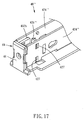
FIG 17 is an assembled perspective view of a magazine of the staple gun automatically applicable to staples of multiple sorts according to a sixth preferred embodiment of the present invention; -
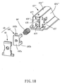
FIG 18 is an exploded view of the magazine and a resilient element of the staple gun automatically applicable to staples of multiple sorts according to the sixth preferred embodiment of the present invention; -
FIG 19 and FIG 20 are cross-sectional views of the magazine and the resilient element of the staple gun automatically applicable to staples of multiple sorts according to the sixth preferred embodiment of the present invention, illustrating their operation; -
FIG 21 is an assembled perspective view of a magazine of the staple gun automatically applicable to staples of multiple sorts according to a variant embodiment of the present invention; -
FIG 22 is a cross-sectional view of the magazine and the resilient element ofFIG 21 ; and -
FIG 23 is a cross-sectional view of a staple gun according to another variant embodiment of the present invention, wherein the staple gun is driven in a way other than manual operation. - In the embodiments below and the accompanying drawings, identical or similar components and structural features thereof are denoted with identical reference numerals. The staple gun mentioned in the present invention is not restricted by the way to drive a staple striking element thereof to strike and eject staples. Staple guns driven manually, electrically, pneumatically or in other equivalent ways should fall within the field and the claims of the present invention.
- Referring to
FIG 1 andFIG 2 , when viewed from the outside, astaple gun 10 automatically applicable to staples of multiple sorts according to a first preferred embodiment of the present invention comprises acasing 20 and anarm 30 extending outward from thecasing 20. Thecasing 20 has therein amagazine 40, astaple delivery element 50, and aresilient element 60 as shown inFIG 3 through FIG. 7 , and a staple striking element 70 (shown inFIG 8 ) driven by thearm 30 to strike and eject staples in a staple striking direction D1. Thearm 30, the staple strikingelement 70, and their operation are well known to persons skilled in the art and thus are not describe herein for the sake of brevity. - Referring to
FIG 1 andFIG 2 , thecasing 20 comprises aleft case element 21, aright case element 22, and afront case element 23. Theleft case element 21 and theright case element 22 are fixed to each other. The rear end of theleft case element 21 and the rear end of theright case element 22 together form anopening 24. Thefront case element 23 is fixed to the front end of theleft case element 21 and the front end of theright case element 22. Thefront case element 23 has a front blocking surface 232 (shown inFIG 8 ) facing theleft case element 21 and theright case element 22. The aforesaid structure of the casing is illustrative rather than restrictive and replaceable by other equivalent structures. - Referring to
FIG 3 through FIG 6 , themagazine 40 comprises abody 42, apressing element 44, and astaple cutting element 46. Thebody 42 is longitudinally slender and comprises abottom plate 422, twolateral plates 424 fixed to thebottom plate 422, and afront plate 426. Thepressing element 44 is pivotally disposed at the rear ends of the twolateral plates 424. Thestaple cutting element 46 is plate-like and is fixed to thefront plate 426. Thestaple cutting element 46 has astaple cutting portion 461. Thestaple cutting portion 461 has atop surface 462, afront end surface 464, and a guidingsurface 466 connected between thetop surface 462 and thefront end surface 464. In this embodiment, the guidingsurface 466 is a plane which slopes relative to thetop surface 462 and thefront end surface 464. Thestaple delivery element 50 straddles the twolateral plates 424 of themagazine 40. A spring (not shown) disposed between the twolateral plates 424 pushes thestaple delivery element 50 in a staple delivering direction D2. Theresilient element 60 is a V-shaped leaf spring with two ends abutting against thebottom plate 422 and thepressing element 44 of themagazine 42, respectively. - After being put together, the
magazine 40, thestaple delivery element 50, and theresilient element 60 are inserted into thecasing 20 through theopening 24. Then, the user gives a press to thepressing element 44 of themagazine 40. The press must be of a strength sufficient to offset the resilience of theresilient element 60, such that thepressing element 44 approaches thebottom plate 422 and enters thecasing 20. Afterward, the user stops the press on thepressing element 44 as soon as themagazine 40 enters thecasing 20 entirely, so as for thepressing element 44 to come into snap-engagement with thecasing 20. At this point in time, themagazine 40, thestaple delivery element 50, and theresilient element 60 are confined to thecasing 20, whereas not only do thefront end surface 464 and the guidingsurface 466 of thestaple cutting portion 461 face thefront blocking surface 232 of thecasing 20, but a clearance 48 (shown inFIGS. 8-10 ) for passing the staples is also disposed between thefront end surface 464 of thestaple cutting portion 461 and thefront blocking surface 232 of thecasing 20. - Referring to
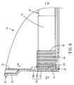
FIG 7 andFIG 8 , a plurality ofstaples 80 connected in array (and including a staple 81) straddles the twolateral plates 424 of themagazine 40. Thestaple delivery element 50 pushes thestaples 80 in the staple delivering direction D2. Hence, theforemost staple 81 abuts against thefront blocking surface 232 of thecasing 20. As the thickness of the staple 81 equals the breadth of theclearance 48 exactly, ahead portion 812 of the staple 81 passes through theclearance 48 as soon as the staplestriking element 70 strikes the staple 81 in the staple striking direction D1, thereby ejecting thestaple 81. - Referring to
FIG. 9 , in the situation where themagazine 40 is loaded with staples 80' of a large thickness, if the staplestriking element 70 strikes a foremost staple 81' abutting against thefront blocking surface 232, not only will the head portion of the staple 81' slide across the guidingsurface 466 of thestaple cutting portion 461 to reach thefront end surface 464, but themagazine 40 will also advance in a clearance adjustment direction D3 opposite to the staple delivering direction D2, such that the breadth of theclearance 48 will be automatically adjusted in accordance with the thickness of the staple 81' to thereby allow the staple 81' to squeeze through theclearance 48. The clearance adjustment is characterized in that: thepressing element 44 of themagazine 40 comes into snap-engagement with thecasing 20 resiliently by means of theresilient element 60; and, when the staple 81' is subjected to a strong force and conveys the strong force to the guidingsurface 466 of themagazine 40, the force component exerted upon themagazine 40 in the clearance adjustment direction D3 offsets the resilience of theresilient element 60, such that the displacement of themagazine 40 in the clearance adjustment direction D3 happens but is too small to undermine the snap-engagement between themagazine 40 and thecasing 20. - Although the aforesaid clearance adjustment is illustrated with n-shaped staples, it not only applies to U-shaped staples which straddle the magazine, but also applies to a T-shaped
staple 81" shown inFIG 12 . As shown inFIG 11 , themagazine 401 is applicable toU-shaped staples 402 in a way that thestaple cutting element 403 and anoutside lateral plate 404 of themagazine 401 both have a guidingsurface staple guiding plate 408 fixedly disposed therein in a way that two embeddingportions 411 of anouter blocking element 410 are embedded in twoholes 412 of thestaple guiding plate 408. Thestaple guiding plate 408 has saidfront blocking surface 407 and a plurality of guidingslots 409 for guiding staples of multiple sorts. - As shown in
FIG 12 , although the staple 81" does not straddle themagazine 40, ahead portion 812" of the staple 81" abuts against thefront end surface 464 and the guidingsurface 466 of themagazine 40 and thus achieves clearance adjustment. Referring toFIG 13 , in this embodiment, thefront case element 23 of thecasing 20 has a staple-guidinggroove 234 dented into thefront blocking surface 232, adapted to enable the staple gun10 to be applicable to T-shaped staples of a very large thickness, and adapted to guide the T-shaped staples being struck by the staplestriking element 70 so as to keep the T-shaped staples parallel to the staple striking direction D 1. - Staples frequently for use with commercially-available staple guns comprises the aforesaid T-shaped staples, U-shaped staples, and n-shaped staples each having a head portion as well as linearly-shaped staples each having staple legs but no head portion. The linearly-shaped staples usually have a relatively small thickness. In view of this, the
staple gun 10 of the present invention is characterized in that: the breadth of theclearance 48 is designed to allow the linearly-shaped staples to squeeze through whenever thestaple cutting portion 461 is not pushed by the staples; and, in the situation where thestaple gun 10 is loaded with staples each having a head portion, thestaple gun 10 will work, provided that the thickness of the staples is less than the least distance d (shown inFIG 9 ) between thetop surface 462 of thestaple cutting portion 461 and thefront blocking surface 232 of thecasing 20. Hence, thestaple gun 10 is automatically applicable to staples of multiple specifications and thicknesses without being tuned by a user, and thus thestaple gun 10 manifests ease of use. Furthermore, thestaple gun 10 has wide application, because it is not only applicable to staples of two or three thicknesses, but also applicable to staples of a specific range of thicknesses. - The guiding
surface 466 of thestaple cutting portion 461 of themagazine 40 of the staple gun automatically applicable to staples of multiple sorts according to the present invention is not limited to a plane that slopes. The staple gun will achieve the objectives of the present invention, provided that head portions of staples are slidable across the guidingsurface 466 and a strike exerted upon the staples generates a force component in the clearance adjustment direction D3. For example, referring toFIG 14 , in a third preferred embodiment of the present invention, a guiding surface 466' of a staple cutting portion 461' of a magazine 40' is a curved surface which has the aforesaid function and effect. - The present invention provides a staple gun automatically applicable to staples of multiple sorts, wherein the aforesaid embodiment is not restrictive of the way of positioning the
magazine 40 in thecasing 20, and thus the aforesaid resilient adjustment of the breadth of theclearance 48 between themagazine 40 and thecasing 20 of the present invention is not necessarily achieved by means of theresilient element 60. For example, referring toFIG 15 , in a fourth preferred embodiment of the present invention, aresilient element 90, which is strip-like and made of a resilient material (such as rubber), is connected between thebody 42 and thestaple cutting element 46 of themagazine 40 to enable thestaple cutting element 46 to be pushed by the staples and resiliently moved, thereby achieving automatic adjustment of the breadth of theclearance 48 in accordance with the thickness of the staples. Alternatively, thebody 42 of themagazine 40 comprises a front half and a rear half, and the resilient element is disposed between the front half and the rear half to achieve the aforesaid function and effect. - Referring to
FIGs. 21 ,22 , aresilient element 65 of themagazine 40 can be replaced with a compression spring. The two ends of theresilient element 65 abut against a positioningportion 66 of thepressing element 44 and a fixingportion 67 of thebottom plate 422, respectively. Thepressing element 44 has anengageably stopping portion 68. Theengageably stopping portion 68 has an adjoiningsurface 69. Theengageably stopping portion 68 enables themagazine 40 to be positioned in thecasing 10. The adjoiningsurface 69 enables theengageably stopping portion 68 to come into snap-engagement with thecasing 10. Theresilient element 65 not only pushes thepressing element 44 but also provides the resilience required for slight reciprocating motion performed by themagazine 40 in the directions D2, D3, such that theresilient element 65 operates in conjunction with thestaple cutting portion 461 to achieve the objectives of the present invention. - The present invention provides a staple gun automatically applicable to staples of multiple sorts, wherein the staple cutting portion is integrally formed at the body of the magazine. For example, referring to
FIG 16 , in a fifth preferred embodiment of the present invention, astaple cutting portion 461" is integrally formed at each of the front ends of twolateral plates 424" of abody 42" of amagazine 40" to achieve the aforesaid function and effect. - Referring to
FIG 17 through FIG 20 , in a sixth preferred embodiment of the present invention, the staple gun automatically applicable to staples of multiple sorts has a magazine 40'" and a resilient element 90'. The magazine 40'" comprises a body 42'" and adisplacement unit 49 movably mounted on thebody 42"'. The resilient element 90' is connected between the body 42'" and thedisplacement unit 49 to achieve the aforesaid function of automatically adjusting clearance in accordance with staple thickness. - Specifically speaking, the body 42'" is similar to the
body 42, except that two snap-engagement holes 427 are disposed at twolateral plates 424"' of thebody 42"', respectively, and a front plate 426'" of the body 42'" extends forward to form a protrudingpost 428, wherein a receivingspace 429 is defined in the front thereof. Thedisplacement unit 49 comprises a slidingblock 492 and thestaple cutting element 46 having thestaple cutting portion 461. The slidingblock 492 comprises aplate 492a as well as a protrudingpost 492c and four snap-engagement portions 492b which are extended from theplate 492a in the same direction. The slidingblock 492 is disposed in the receivingspace 429. The snap-engagement portions 492b are each movably forward and backward to therefore come into snap-engagement with the snap-engagement holes 427, respectively. Thestaple cutting element 46 is fixed to theplate 492a. The resilient element 90' is a compression spring with two ends disposed around the two protrudingposts plate 492a, respectively, to provide a resilient restoring force under which the slidingblock 492 and thestaple cutting element 46 are pushed in the staple delivering direction D2. - Referring to
FIG 19 , before thestaple cutting element 46 is pushed by the staples, theplate 492a of the slidingblock 492 protrudes from thebody 42"', such that agap 468 is formed between thestaple cutting element 46 and thebody 42"', wherein thegap 468 enables thestaple cutting element 46 being pushed by the staples to move in the clearance adjustment direction D3 (shown inFIG 20 ). As regards thedisplacement unit 49 in this embodiment, thestaple cutting element 46 is fixed to the slidingblock 492 by means of a screw (not shown); however, it is also feasible for thestaple cutting element 46 and the slidingblock 492 to be integrally formed as a unitary structure. - Constituent elements disclosed in the aforesaid embodiments of the present invention are illustrative rather than restrictive of the scope of the present invention. Changes or replacements of other equivalent elements and other equivalent ways to drive the staple
striking element 70, such as theelectric driving unit 90 shown inFIG 23 , should fall within the claims of the present invention.
Claims (11)
- A staple gun (10) automatically applicable to staples (80) of multiple sorts, the staple gun (10) comprising:a casing (20) having a front blocking surface (232);a magazine (40) comprising a body (42) and being disposed in the casing (20) and adapted to hold a plurality of staples (80);a staple delivery element (50) disposed at the magazine (40) and adapted to push the staples (80) in the magazine (40) in a staple delivering direction (D2) such that one of the staples (80) abuts against the front blocking surface (232) of the casing (20);characterized in that the magazine (40) further comprisesa staple cutting element (46) having a staple cutting portion (461), the staple cutting portion (461) having a top surface (462), a front end surface (464), and a guiding surface (466) connected between the top surface (462) and the front end surface (464), wherein the front end surface (464) and the guiding surface (466) of the staple cutting portion (461) face the front blocking surface (232) of the casing (20), the magazine further comprising a clearance (48) for passing the staples (80) disposed between the front end surface (464) of the staple cutting portion (461) and the front blocking surface (232) of the casing (20), anda resilient element (60) disposed at the magazine (40) and providing resilience to the staple cutting element (46) in the staple delivering direction (D2).
- The staple gun (10) automatically applicable to staples (80) of multiple sorts of claim 1, which is characterized in that the guiding surface (466) of the staple cutting portion (461) is a plane which slopes relative to the top surface (462) and the front end surface (464).
- The staple gun (10) automatically applicable to staples (80) of multiple sorts of claim 1, which is characterized in that the guiding surface (466) of the staple cutting portion (461) is a curved surface.
- The staple gun (10) automatically applicable to staples (80) of multiple sorts of claim 1, which is characterized in that the magazine (40) comprises a pressing element (44) pivotally disposed at the body (42) adapted to enter the casing (20) and come into snap-engagement with the casing (20).
- The staple gun (10) automatically applicable to staples (80) of multiple sorts of claim 1, which is characterized in that the magazine (40) comprises a body (42) and a staple cutting element (46) fixed to an end of the body (42), and the staple cutting portion (461) is disposed at the staple cutting element (46).
- The staple gun (10) automatically applicable to staples (80) of multiple sorts of claim 1, which is characterized in that the magazine (40) comprises a body (42) and a staple cutting element (46) having the staple cutting portion (461), and the resilient element (60) is connected between the body (42) and the staple cutting element (46).
- The staple gun (10) automatically applicable to staples (80) of multiple sorts of claim 1, which is characterized in that the magazine (40) comprises a body (42), and the staple cutting portion (461) is integrally formed at an end of the body (42).
- The staple gun (10) automatically applicable to staples (80) of multiple sorts of claim 7, which is characterized in that the body (42) of the magazine (40) comprises two lateral plates (424) each having the staple cutting portion (461).
- The staple gun (10) automatically applicable to staples (80) of multiple sorts of claim 1, which is characterized in that the casing (20) having a staple-guiding groove (234) dented into the front blocking surface (232).
- The staple gun (10) automatically applicable to staples (80) of multiple sorts of claim 1, which is characterized in that the magazine (40) comprises a body (42) and a displacement unit (49) movably mounted on the body (42), wherein the staple cutting portion (461) is disposed at the displacement unit (49), wherein the resilient element (60) is connected between the body (42) and the displacement unit (49).
- The staple gun automatically applicable to staples of multiple sorts of claim 1, which is characterized in that the magazine (401) comprises a staple guiding plate (408) having said front blocking surface (407) and a plurality of guiding slots (409).
Applications Claiming Priority (1)
| Application Number | Priority Date | Filing Date | Title |
|---|---|---|---|
| TW102129547A TW201507827A (en) | 2013-08-16 | 2013-08-16 | Nail gun automatically applied to various nails |
Publications (2)
| Publication Number | Publication Date |
|---|---|
| EP2837470A1 EP2837470A1 (en) | 2015-02-18 |
| EP2837470B1 true EP2837470B1 (en) | 2016-07-13 |
Family
ID=50726470
Family Applications (1)
| Application Number | Title | Priority Date | Filing Date |
|---|---|---|---|
| EP14169098.2A Active EP2837470B1 (en) | 2013-08-16 | 2014-05-20 | Staple gun automatically applicable to staples of multiple sorts |
Country Status (4)
| Country | Link |
|---|---|
| US (1) | US9669530B2 (en) |
| EP (1) | EP2837470B1 (en) |
| DE (1) | DE202014100175U1 (en) |
| TW (1) | TW201507827A (en) |
Cited By (1)
| Publication number | Priority date | Publication date | Assignee | Title |
|---|---|---|---|---|
| US11633839B2 (en) | 2016-03-22 | 2023-04-25 | Stanley Black & Decker, Inc. | Safety device for tackers |
Families Citing this family (8)
| Publication number | Priority date | Publication date | Assignee | Title |
|---|---|---|---|---|
| US20140319196A1 (en) * | 2013-04-25 | 2014-10-30 | Tsung- Wen Huang | Staple cartridge for tacker |
| TW201507827A (en) * | 2013-08-16 | 2015-03-01 | Same Yong Ind Co Ltd | Nail gun automatically applied to various nails |
| TWM476857U (en) * | 2013-12-11 | 2014-04-21 | Wistron Corp | Screwing accessory device |
| US20170225310A1 (en) * | 2016-02-10 | 2017-08-10 | Tsung-Wen Huang | Operation assembly of a hammer tacker |
| CN109277989A (en) * | 2017-07-19 | 2019-01-29 | 丰民金属工业股份有限公司 | Nail kit component and nail gun comprising it |
| CN109571372B (en) * | 2017-09-29 | 2024-04-16 | 杭州巨星科技股份有限公司 | Multifunctional nailing gun |
| US11597548B2 (en) | 2019-08-23 | 2023-03-07 | Max Co., Ltd. | Binding machine |
| JP7422982B2 (en) * | 2019-08-23 | 2024-01-29 | マックス株式会社 | Binding machine |
Family Cites Families (22)
| Publication number | Priority date | Publication date | Assignee | Title |
|---|---|---|---|---|
| DE4109362A1 (en) * | 1991-03-22 | 1992-09-24 | Bosch Gmbh Robert | DRIVING DEVICE FOR STAPLES |
| US5794832A (en) * | 1997-05-06 | 1998-08-18 | Chen; Tung-I | Staple magazine for a stapler |
| US5931364A (en) * | 1997-06-25 | 1999-08-03 | Acme Staple Company, Inc. | Fastening tool for securing an object to a substrate |
| US6871768B2 (en) * | 1999-06-11 | 2005-03-29 | Acco Brands, Inc. | Stapler for forming staples to various sizes |
| US6715657B2 (en) * | 2002-04-29 | 2004-04-06 | Mu-Yu Chen | Magazine for use in nail stapler |
| CN2670065Y (en) * | 2003-12-05 | 2005-01-12 | 益卓有限公司 | Nail box structure of nail shooter |
| WO2005102613A1 (en) * | 2004-04-20 | 2005-11-03 | Romeo Maestri & Figli S.P.A. | Stapler with adapter |
| US20060231582A1 (en) * | 2005-04-14 | 2006-10-19 | Eastway Fair Company Limited | Stapler |
| TWI271286B (en) * | 2005-08-02 | 2007-01-21 | Apex Mfg Co Ltd | Nail case structure of staple gun which can guide various sizes of nail automatically |
| CN200951551Y (en) * | 2006-09-19 | 2007-09-26 | 朱益民 | Spring box apparatus of pneumatic nailing gun |
| CN201061875Y (en) * | 2007-05-29 | 2008-05-21 | 车王电子股份有限公司 | Nail box for both U-shaped nail and T-shaped nail |
| TW200920567A (en) * | 2007-11-15 | 2009-05-16 | Apex Mfg Co Ltd | A staple gun which is suitable for multiple types of staple nail |
| CN201120599Y (en) * | 2007-11-23 | 2008-09-24 | 台州市大江实业有限公司 | Nail gun nail box apparatus for T shaped, L shaped or U shaped nail |
| TWM355151U (en) * | 2008-07-10 | 2009-04-21 | Zhuang Kun Hu | Nailing gun applicable to various nail sizes |
| TWI369285B (en) * | 2010-01-08 | 2012-08-01 | Apex Mfg Co Ltd | Nailing device adapted for nail units with different sizes |
| TWI409145B (en) * | 2010-01-22 | 2013-09-21 | Apex Mfg Co Ltd | Nailing device adapted for nail units with different sizes |
| TWI383867B (en) * | 2010-08-20 | 2013-02-01 | Apex Mfg Co Ltd | Nail guider and nailing device having the same |
| US20120111916A1 (en) * | 2010-11-05 | 2012-05-10 | Same Yong Industrial Co., Ltd. | Stapler |
| TWI397458B (en) * | 2011-05-10 | 2013-06-01 | Apex Mfg Co Ltd | Nail guider and nailing device including the same |
| US9808924B2 (en) * | 2012-01-13 | 2017-11-07 | Apex Mfg. Co., Ltd. | Nail gun |
| TWI549787B (en) * | 2012-02-29 | 2016-09-21 | Nail guns | |
| TW201507827A (en) * | 2013-08-16 | 2015-03-01 | Same Yong Ind Co Ltd | Nail gun automatically applied to various nails |
-
2013
- 2013-08-16 TW TW102129547A patent/TW201507827A/en unknown
- 2013-11-27 US US14/092,629 patent/US9669530B2/en active Active
-
2014
- 2014-01-16 DE DE202014100175.1U patent/DE202014100175U1/en not_active Expired - Lifetime
- 2014-05-20 EP EP14169098.2A patent/EP2837470B1/en active Active
Cited By (1)
| Publication number | Priority date | Publication date | Assignee | Title |
|---|---|---|---|---|
| US11633839B2 (en) | 2016-03-22 | 2023-04-25 | Stanley Black & Decker, Inc. | Safety device for tackers |
Also Published As
| Publication number | Publication date |
|---|---|
| DE202014100175U1 (en) | 2014-04-29 |
| EP2837470A1 (en) | 2015-02-18 |
| US20150048138A1 (en) | 2015-02-19 |
| TW201507827A (en) | 2015-03-01 |
| TWI510341B (en) | 2015-12-01 |
| US9669530B2 (en) | 2017-06-06 |
Similar Documents
| Publication | Publication Date | Title |
|---|---|---|
| EP2837470B1 (en) | Staple gun automatically applicable to staples of multiple sorts | |
| US8205778B2 (en) | Nailing device adapted for nail units of different sizes | |
| US7559447B2 (en) | Nail-driving device with safety unit | |
| US6745474B1 (en) | Blade pushing device of cutting knives | |
| US7413105B1 (en) | Pushing device of drawer type magazine for nail gun | |
| US9808924B2 (en) | Nail gun | |
| EP1230070B1 (en) | Nail magazine for a power nailer | |
| US8646672B2 (en) | Nail positioning member of nail slot of nail gun | |
| US6860416B1 (en) | Single-shot nail stapler | |
| US7520413B1 (en) | Jam-resistant tacker apparatus | |
| TWI413578B (en) | Staple gun | |
| US20210039238A1 (en) | Safety device for tackers | |
| US20080067089A1 (en) | Nail magazine for a power nail-driving tool | |
| EP2450154B1 (en) | Stapler | |
| US7004368B1 (en) | Nailing gun having improved nail pusher | |
| US7497364B2 (en) | Adjusting device for magazine of nailers | |
| EP3073811B1 (en) | Slide rail assembly | |
| EP3243605B1 (en) | Safety device for tackers | |
| US20140026409A1 (en) | Bar Connecting Apparatus and a String of Clips Usable Therewith | |
| US9505116B2 (en) | Override mechanism for nailers | |
| US5967396A (en) | Staples adjusting device for a magazine of a power stapler | |
| US20080264998A1 (en) | Nail positioning device for nailers | |
| US9993912B2 (en) | Nail pushing device for nail gun | |
| CN112060014B (en) | Nail gun | |
| CN212240882U (en) | Nail pusher and stapler with same |
Legal Events
| Date | Code | Title | Description |
|---|---|---|---|
| 17P | Request for examination filed |
Effective date: 20140520 |
|
| AK | Designated contracting states |
Kind code of ref document: A1 Designated state(s): AL AT BE BG CH CY CZ DE DK EE ES FI FR GB GR HR HU IE IS IT LI LT LU LV MC MK MT NL NO PL PT RO RS SE SI SK SM TR |
|
| AX | Request for extension of the european patent |
Extension state: BA ME |
|
| PUAI | Public reference made under article 153(3) epc to a published international application that has entered the european phase |
Free format text: ORIGINAL CODE: 0009012 |
|
| R17P | Request for examination filed (corrected) |
Effective date: 20150817 |
|
| RBV | Designated contracting states (corrected) |
Designated state(s): AL AT BE BG CH CY CZ DE DK EE ES FI FR GB GR HR HU IE IS IT LI LT LU LV MC MK MT NL NO PL PT RO RS SE SI SK SM TR |
|
| GRAP | Despatch of communication of intention to grant a patent |
Free format text: ORIGINAL CODE: EPIDOSNIGR1 |
|
| INTG | Intention to grant announced |
Effective date: 20160216 |
|
| GRAS | Grant fee paid |
Free format text: ORIGINAL CODE: EPIDOSNIGR3 |
|
| GRAA | (expected) grant |
Free format text: ORIGINAL CODE: 0009210 |
|
| AK | Designated contracting states |
Kind code of ref document: B1 Designated state(s): AL AT BE BG CH CY CZ DE DK EE ES FI FR GB GR HR HU IE IS IT LI LT LU LV MC MK MT NL NO PL PT RO RS SE SI SK SM TR |
|
| REG | Reference to a national code |
Ref country code: GB Ref legal event code: FG4D |
|
| REG | Reference to a national code |
Ref country code: AT Ref legal event code: REF Ref document number: 811907 Country of ref document: AT Kind code of ref document: T Effective date: 20160715 Ref country code: CH Ref legal event code: EP Ref country code: CH Ref legal event code: NV Representative=s name: ROMAN VUILLE, CH |
|
| REG | Reference to a national code |
Ref country code: IE Ref legal event code: FG4D |
|
| REG | Reference to a national code |
Ref country code: DE Ref legal event code: R096 Ref document number: 602014002622 Country of ref document: DE |
|
| REG | Reference to a national code |
Ref country code: LT Ref legal event code: MG4D |
|
| REG | Reference to a national code |
Ref country code: NL Ref legal event code: MP Effective date: 20160713 |
|
| REG | Reference to a national code |
Ref country code: AT Ref legal event code: MK05 Ref document number: 811907 Country of ref document: AT Kind code of ref document: T Effective date: 20160713 |
|
| PG25 | Lapsed in a contracting state [announced via postgrant information from national office to epo] |
Ref country code: HR Free format text: LAPSE BECAUSE OF FAILURE TO SUBMIT A TRANSLATION OF THE DESCRIPTION OR TO PAY THE FEE WITHIN THE PRESCRIBED TIME-LIMIT Effective date: 20160713 Ref country code: IS Free format text: LAPSE BECAUSE OF FAILURE TO SUBMIT A TRANSLATION OF THE DESCRIPTION OR TO PAY THE FEE WITHIN THE PRESCRIBED TIME-LIMIT Effective date: 20161113 Ref country code: NL Free format text: LAPSE BECAUSE OF FAILURE TO SUBMIT A TRANSLATION OF THE DESCRIPTION OR TO PAY THE FEE WITHIN THE PRESCRIBED TIME-LIMIT Effective date: 20160713 Ref country code: LT Free format text: LAPSE BECAUSE OF FAILURE TO SUBMIT A TRANSLATION OF THE DESCRIPTION OR TO PAY THE FEE WITHIN THE PRESCRIBED TIME-LIMIT Effective date: 20160713 Ref country code: RS Free format text: LAPSE BECAUSE OF FAILURE TO SUBMIT A TRANSLATION OF THE DESCRIPTION OR TO PAY THE FEE WITHIN THE PRESCRIBED TIME-LIMIT Effective date: 20160713 Ref country code: IT Free format text: LAPSE BECAUSE OF FAILURE TO SUBMIT A TRANSLATION OF THE DESCRIPTION OR TO PAY THE FEE WITHIN THE PRESCRIBED TIME-LIMIT Effective date: 20160713 Ref country code: FI Free format text: LAPSE BECAUSE OF FAILURE TO SUBMIT A TRANSLATION OF THE DESCRIPTION OR TO PAY THE FEE WITHIN THE PRESCRIBED TIME-LIMIT Effective date: 20160713 Ref country code: NO Free format text: LAPSE BECAUSE OF FAILURE TO SUBMIT A TRANSLATION OF THE DESCRIPTION OR TO PAY THE FEE WITHIN THE PRESCRIBED TIME-LIMIT Effective date: 20161013 |
|
| PG25 | Lapsed in a contracting state [announced via postgrant information from national office to epo] |
Ref country code: PT Free format text: LAPSE BECAUSE OF FAILURE TO SUBMIT A TRANSLATION OF THE DESCRIPTION OR TO PAY THE FEE WITHIN THE PRESCRIBED TIME-LIMIT Effective date: 20161114 Ref country code: LV Free format text: LAPSE BECAUSE OF FAILURE TO SUBMIT A TRANSLATION OF THE DESCRIPTION OR TO PAY THE FEE WITHIN THE PRESCRIBED TIME-LIMIT Effective date: 20160713 Ref country code: SE Free format text: LAPSE BECAUSE OF FAILURE TO SUBMIT A TRANSLATION OF THE DESCRIPTION OR TO PAY THE FEE WITHIN THE PRESCRIBED TIME-LIMIT Effective date: 20160713 Ref country code: PL Free format text: LAPSE BECAUSE OF FAILURE TO SUBMIT A TRANSLATION OF THE DESCRIPTION OR TO PAY THE FEE WITHIN THE PRESCRIBED TIME-LIMIT Effective date: 20160713 Ref country code: ES Free format text: LAPSE BECAUSE OF FAILURE TO SUBMIT A TRANSLATION OF THE DESCRIPTION OR TO PAY THE FEE WITHIN THE PRESCRIBED TIME-LIMIT Effective date: 20160713 Ref country code: BE Free format text: LAPSE BECAUSE OF FAILURE TO SUBMIT A TRANSLATION OF THE DESCRIPTION OR TO PAY THE FEE WITHIN THE PRESCRIBED TIME-LIMIT Effective date: 20160713 Ref country code: GR Free format text: LAPSE BECAUSE OF FAILURE TO SUBMIT A TRANSLATION OF THE DESCRIPTION OR TO PAY THE FEE WITHIN THE PRESCRIBED TIME-LIMIT Effective date: 20161014 Ref country code: AT Free format text: LAPSE BECAUSE OF FAILURE TO SUBMIT A TRANSLATION OF THE DESCRIPTION OR TO PAY THE FEE WITHIN THE PRESCRIBED TIME-LIMIT Effective date: 20160713 |
|
| REG | Reference to a national code |
Ref country code: DE Ref legal event code: R097 Ref document number: 602014002622 Country of ref document: DE |
|
| PG25 | Lapsed in a contracting state [announced via postgrant information from national office to epo] |
Ref country code: EE Free format text: LAPSE BECAUSE OF FAILURE TO SUBMIT A TRANSLATION OF THE DESCRIPTION OR TO PAY THE FEE WITHIN THE PRESCRIBED TIME-LIMIT Effective date: 20160713 Ref country code: RO Free format text: LAPSE BECAUSE OF FAILURE TO SUBMIT A TRANSLATION OF THE DESCRIPTION OR TO PAY THE FEE WITHIN THE PRESCRIBED TIME-LIMIT Effective date: 20160713 |
|
| PLBE | No opposition filed within time limit |
Free format text: ORIGINAL CODE: 0009261 |
|
| STAA | Information on the status of an ep patent application or granted ep patent |
Free format text: STATUS: NO OPPOSITION FILED WITHIN TIME LIMIT |
|
| REG | Reference to a national code |
Ref country code: FR Ref legal event code: PLFP Year of fee payment: 4 |
|
| PG25 | Lapsed in a contracting state [announced via postgrant information from national office to epo] |
Ref country code: SK Free format text: LAPSE BECAUSE OF FAILURE TO SUBMIT A TRANSLATION OF THE DESCRIPTION OR TO PAY THE FEE WITHIN THE PRESCRIBED TIME-LIMIT Effective date: 20160713 Ref country code: CZ Free format text: LAPSE BECAUSE OF FAILURE TO SUBMIT A TRANSLATION OF THE DESCRIPTION OR TO PAY THE FEE WITHIN THE PRESCRIBED TIME-LIMIT Effective date: 20160713 Ref country code: SM Free format text: LAPSE BECAUSE OF FAILURE TO SUBMIT A TRANSLATION OF THE DESCRIPTION OR TO PAY THE FEE WITHIN THE PRESCRIBED TIME-LIMIT Effective date: 20160713 Ref country code: DK Free format text: LAPSE BECAUSE OF FAILURE TO SUBMIT A TRANSLATION OF THE DESCRIPTION OR TO PAY THE FEE WITHIN THE PRESCRIBED TIME-LIMIT Effective date: 20160713 Ref country code: BG Free format text: LAPSE BECAUSE OF FAILURE TO SUBMIT A TRANSLATION OF THE DESCRIPTION OR TO PAY THE FEE WITHIN THE PRESCRIBED TIME-LIMIT Effective date: 20161013 |
|
| 26N | No opposition filed |
Effective date: 20170418 |
|
| PG25 | Lapsed in a contracting state [announced via postgrant information from national office to epo] |
Ref country code: SI Free format text: LAPSE BECAUSE OF FAILURE TO SUBMIT A TRANSLATION OF THE DESCRIPTION OR TO PAY THE FEE WITHIN THE PRESCRIBED TIME-LIMIT Effective date: 20160713 Ref country code: LU Free format text: LAPSE BECAUSE OF NON-PAYMENT OF DUE FEES Effective date: 20170531 |
|
| PG25 | Lapsed in a contracting state [announced via postgrant information from national office to epo] |
Ref country code: MC Free format text: LAPSE BECAUSE OF FAILURE TO SUBMIT A TRANSLATION OF THE DESCRIPTION OR TO PAY THE FEE WITHIN THE PRESCRIBED TIME-LIMIT Effective date: 20160713 |
|
| PG25 | Lapsed in a contracting state [announced via postgrant information from national office to epo] |
Ref country code: LU Free format text: LAPSE BECAUSE OF NON-PAYMENT OF DUE FEES Effective date: 20170520 |
|
| REG | Reference to a national code |
Ref country code: FR Ref legal event code: PLFP Year of fee payment: 5 |
|
| PG25 | Lapsed in a contracting state [announced via postgrant information from national office to epo] |
Ref country code: MT Free format text: LAPSE BECAUSE OF NON-PAYMENT OF DUE FEES Effective date: 20170520 |
|
| PG25 | Lapsed in a contracting state [announced via postgrant information from national office to epo] |
Ref country code: AL Free format text: LAPSE BECAUSE OF FAILURE TO SUBMIT A TRANSLATION OF THE DESCRIPTION OR TO PAY THE FEE WITHIN THE PRESCRIBED TIME-LIMIT Effective date: 20160713 |
|
| PG25 | Lapsed in a contracting state [announced via postgrant information from national office to epo] |
Ref country code: HU Free format text: LAPSE BECAUSE OF FAILURE TO SUBMIT A TRANSLATION OF THE DESCRIPTION OR TO PAY THE FEE WITHIN THE PRESCRIBED TIME-LIMIT; INVALID AB INITIO Effective date: 20140520 |
|
| PG25 | Lapsed in a contracting state [announced via postgrant information from national office to epo] |
Ref country code: CY Free format text: LAPSE BECAUSE OF FAILURE TO SUBMIT A TRANSLATION OF THE DESCRIPTION OR TO PAY THE FEE WITHIN THE PRESCRIBED TIME-LIMIT Effective date: 20160713 |
|
| PG25 | Lapsed in a contracting state [announced via postgrant information from national office to epo] |
Ref country code: MK Free format text: LAPSE BECAUSE OF FAILURE TO SUBMIT A TRANSLATION OF THE DESCRIPTION OR TO PAY THE FEE WITHIN THE PRESCRIBED TIME-LIMIT Effective date: 20160713 |
|
| PG25 | Lapsed in a contracting state [announced via postgrant information from national office to epo] |
Ref country code: TR Free format text: LAPSE BECAUSE OF FAILURE TO SUBMIT A TRANSLATION OF THE DESCRIPTION OR TO PAY THE FEE WITHIN THE PRESCRIBED TIME-LIMIT Effective date: 20160713 |
|
| PGFP | Annual fee paid to national office [announced via postgrant information from national office to epo] |
Ref country code: IE Payment date: 20230516 Year of fee payment: 10 Ref country code: FR Payment date: 20230517 Year of fee payment: 10 Ref country code: DE Payment date: 20230531 Year of fee payment: 10 Ref country code: CH Payment date: 20230605 Year of fee payment: 10 |
|
| PGFP | Annual fee paid to national office [announced via postgrant information from national office to epo] |
Ref country code: GB Payment date: 20230522 Year of fee payment: 10 |