EP2837439A2 - A method of reducing wrinkles in pressed sheet metal components - Google Patents
A method of reducing wrinkles in pressed sheet metal components Download PDFInfo
- Publication number
- EP2837439A2 EP2837439A2 EP14177279.8A EP14177279A EP2837439A2 EP 2837439 A2 EP2837439 A2 EP 2837439A2 EP 14177279 A EP14177279 A EP 14177279A EP 2837439 A2 EP2837439 A2 EP 2837439A2
- Authority
- EP
- European Patent Office
- Prior art keywords
- slot
- blank
- sheet metal
- profiled
- hole
- Prior art date
- Legal status (The legal status is an assumption and is not a legal conclusion. Google has not performed a legal analysis and makes no representation as to the accuracy of the status listed.)
- Withdrawn
Links
Images


Classifications
-
- B—PERFORMING OPERATIONS; TRANSPORTING
- B23—MACHINE TOOLS; METAL-WORKING NOT OTHERWISE PROVIDED FOR
- B23P—METAL-WORKING NOT OTHERWISE PROVIDED FOR; COMBINED OPERATIONS; UNIVERSAL MACHINE TOOLS
- B23P13/00—Making metal objects by operations essentially involving machining but not covered by a single other subclass
-
- B—PERFORMING OPERATIONS; TRANSPORTING
- B21—MECHANICAL METAL-WORKING WITHOUT ESSENTIALLY REMOVING MATERIAL; PUNCHING METAL
- B21D—WORKING OR PROCESSING OF SHEET METAL OR METAL TUBES, RODS OR PROFILES WITHOUT ESSENTIALLY REMOVING MATERIAL; PUNCHING METAL
- B21D35/00—Combined processes according to or processes combined with methods covered by groups B21D1/00 - B21D31/00
- B21D35/001—Shaping combined with punching, e.g. stamping and perforating
-
- B—PERFORMING OPERATIONS; TRANSPORTING
- B21—MECHANICAL METAL-WORKING WITHOUT ESSENTIALLY REMOVING MATERIAL; PUNCHING METAL
- B21D—WORKING OR PROCESSING OF SHEET METAL OR METAL TUBES, RODS OR PROFILES WITHOUT ESSENTIALLY REMOVING MATERIAL; PUNCHING METAL
- B21D1/00—Straightening, restoring form or removing local distortions of sheet metal or specific articles made therefrom; Stretching sheet metal combined with rolling
- B21D1/06—Removing local distortions
-
- B—PERFORMING OPERATIONS; TRANSPORTING
- B21—MECHANICAL METAL-WORKING WITHOUT ESSENTIALLY REMOVING MATERIAL; PUNCHING METAL
- B21D—WORKING OR PROCESSING OF SHEET METAL OR METAL TUBES, RODS OR PROFILES WITHOUT ESSENTIALLY REMOVING MATERIAL; PUNCHING METAL
- B21D11/00—Bending not restricted to forms of material mentioned in only one of groups B21D5/00, B21D7/00, B21D9/00; Bending not provided for in groups B21D5/00 - B21D9/00; Twisting
- B21D11/08—Bending by altering the thickness of part of the cross-section of the work
-
- B—PERFORMING OPERATIONS; TRANSPORTING
- B21—MECHANICAL METAL-WORKING WITHOUT ESSENTIALLY REMOVING MATERIAL; PUNCHING METAL
- B21D—WORKING OR PROCESSING OF SHEET METAL OR METAL TUBES, RODS OR PROFILES WITHOUT ESSENTIALLY REMOVING MATERIAL; PUNCHING METAL
- B21D22/00—Shaping without cutting, by stamping, spinning, or deep-drawing
-
- B—PERFORMING OPERATIONS; TRANSPORTING
- B21—MECHANICAL METAL-WORKING WITHOUT ESSENTIALLY REMOVING MATERIAL; PUNCHING METAL
- B21D—WORKING OR PROCESSING OF SHEET METAL OR METAL TUBES, RODS OR PROFILES WITHOUT ESSENTIALLY REMOVING MATERIAL; PUNCHING METAL
- B21D22/00—Shaping without cutting, by stamping, spinning, or deep-drawing
- B21D22/20—Deep-drawing
- B21D22/201—Work-pieces; preparation of the work-pieces, e.g. lubricating, coating
-
- B—PERFORMING OPERATIONS; TRANSPORTING
- B21—MECHANICAL METAL-WORKING WITHOUT ESSENTIALLY REMOVING MATERIAL; PUNCHING METAL
- B21D—WORKING OR PROCESSING OF SHEET METAL OR METAL TUBES, RODS OR PROFILES WITHOUT ESSENTIALLY REMOVING MATERIAL; PUNCHING METAL
- B21D22/00—Shaping without cutting, by stamping, spinning, or deep-drawing
- B21D22/20—Deep-drawing
- B21D22/26—Deep-drawing for making peculiarly, e.g. irregularly, shaped articles
-
- B—PERFORMING OPERATIONS; TRANSPORTING
- B21—MECHANICAL METAL-WORKING WITHOUT ESSENTIALLY REMOVING MATERIAL; PUNCHING METAL
- B21D—WORKING OR PROCESSING OF SHEET METAL OR METAL TUBES, RODS OR PROFILES WITHOUT ESSENTIALLY REMOVING MATERIAL; PUNCHING METAL
- B21D5/00—Bending sheet metal along straight lines, e.g. to form simple curves
Definitions
- the present invention relates to a method of reducing wrinkles in pressed sheet metal components and particularly, but not exclusively, to a method of reducing wrinkles in thin walled sheet metal pressings.
- slots and cut-outs in two dimensional metal sheets prior to forming these flat sheets into three dimensional formed components.
- Such slots and cut-outs are typically produced using laser cutting techniques which can provide net shape blanks. These blanks can then be bent to shape and welded together very cheaply and easily.
- these slots and cut-outs are generally cut into the external peripheral edge(s) of the blank, as shown in Figure 1 , thereby requiring at least one bend to close the cut edges together.
- a known difficulty with such forming methods is that they do not permit stretching and forming of complex three-dimensional geometries on pressed components using simple tooling. This generally results in formed components having excess material thereby causing wrinkles in the sheet material's surfaces.
- a method of forming a sheet metal component comprising the steps of:
- the method of the invention provides for a method of forming sheet metal to create complicated compound curves without the need for the sheet metal to be pressed sufficiently to change the material thickness. This means that the pressing operation(s) can be carried out at lower temperatures and pressures thereby making the method of the invention cheaper and easier for a user.
- a further advantage of the method of the invention is that it enables the forming process to be completed using only a single pressing operation and a single stage press capability. This means that the required tooling is simple and inexpensive in comparison to traditional multi-stage press tooling which requires a press that applies pressure from two or more directions.
- a further benefit of the method of the invention is that the finished sheet metal component incurs reduced surface deformation which in turn provides a more accurate surface profile without the need for costly and time-consuming reworking.
- step (iii) comprises the additional step of cutting a hole at one end of the slot, the hole having a diameter greater than a lateral width of the slot.
- step (iii) comprises the additional step of:
- the use of a hole having a larger diameter than the width of the slot can simplify the step of welding up the slot after the pressing operation(s) have been performed on the blank.
- the or each slot has a constant lateral width along the length of the slot.
- the finished sheet metal component has pressed features that are formed symmetrically about an axis along the component, it may be advantageous to form slots of constant lateral width along corresponding wrinkle lines.
- the or each slot has a lateral width that tapers in a direction extending from a first end of the slot towards an opposite second end of the slot.
- the finished sheet metal component has pressed features that are formed asymmetrically about an axis along the component, it may be advantageous to form slots having a tapered width along corresponding wrinkle lines.
- step (v) comprises the step of:
- the welding operation(s) are performed over the entire length of the slot. This provides for maximum structural integrity in the finished component. However, depending upon the length of the slot, it may be necessary to heat treat the finished component to ameliorate any adverse stress concentration resulting from the heat input from the welding process(es).
- the welding operation(s) are carried out over only part or parts of the length of the slot. This may enable the part to be used without a need for further heat treatment thus reducing costs and making the method quicker.
- the partial welding of the slot may reduce the structural strength of the component.
- aspects of the invention provide devices, methods and systems which include and/or implement some or all of the actions described herein.
- the illustrative aspects of the invention are designed to solve one or more of the problems herein described and/or one or more other problems not discussed.
- InconelTM 718 Some metals are easier to mechanically work than others particularly with regard to making complex curvatures.
- An example of this is InconelTM 718.
- InconelTM 718 requires very high pressures to plastically deform in a cold or low temperature mould. When being worked and formed in sheet metal where there is a requirement for an area to be compressed this presents a problem.
- the sheet material may buckle or wrinkle. These wrinkles are caused through excess material being squeezed and pushing away from the mould wall.
- the method of the invention provides a means of removing material so that the component can be formed more easily.
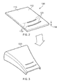
- Figures 2 and 3 show an unformed sheet metal blank and a finished sheet metal component that has been processed by the method of the invention.
- the profiled sheet metal blank 110 has a surface 112 and a thickness 114.
- the sheet metal is an InconelTM 718 alloy.
- the method of the invention is equally applicable to other high strength age-hardening metal alloys.
- a typical limiting material composition for InconelTM 718 is set out below in Table 1. Table 1.
- the geometry of the finished sheet metal component 150 is analysed by means of suitable computer software, such as finite element analysis, to determine whether a compressive stress in the sheet material at any point in the forming process exceeds a critical buckling stress value for the material.
- any such compressive buckling stresses are identified they can be plotted on the surface 112 of the profiled blank 110. These buckling stresses enable prediction of the formation of wrinkles in the surface of the material. This type of analysis is well known in the metal forming industry and is commonly used to predict the onset of wrinkling in, for example, deep drawn metal pressings.
- the lines 130 along which the wrinkles are predicted to form are lines along which the InconelTM material would need to be compressed at very high pressure if the formation wrinkles is to be avoided.
- the key step to the method of the invention is the cutting of one or more slots 120 through the surface 112 of the profiled blank 110 to thereby reduce the volume of material that is to be squeezed into the mould cavity. These slots 120 are aligned with the predicted wrinkle lines 130.
- the slot 120 is cut through the thickness 114 of the profiled blank 110 by a laser cutting process. In other arrangements another suitable cutting technique may be used to form the slot 120.
- the geometry, direction and length of the slot 120 will be determined by the wrinkle line 130 which in turn has been predicted from the computer analysis of the forming operation.
- the geometry of the wrinkle line(s) 130 may be determined by producing a test forming of the finished sheet metal component 150 and using the location of the wrinkle line(s) 130 that are formed as a guide to the location of the slot(s) on a further profiled blank 110. In other words a trial press process is used to determine the location of the wrinkle line(s).
- the resulting material deformation causes the slot(s) 120 to close up, as shown in Figure 3 . Any residual gap along the slot 130 must be small enough in the formed condition that the areas were once slots 130 can now be welded closed and dressed back to the surface profile.
- the profiled blank 110 now with slots 220 having a hole 240 at each end is press formed in the same manner as described above to form a finished sheet metal component 250 in which the slots 220 have closed up along their length.
- the slots 220 can then be welded up along their length with the holes 240 acting as aids to the start and end of the weld runs.
Landscapes
- Engineering & Computer Science (AREA)
- Mechanical Engineering (AREA)
- Shaping Metal By Deep-Drawing, Or The Like (AREA)
Abstract
Description
- The present invention relates to a method of reducing wrinkles in pressed sheet metal components and particularly, but not exclusively, to a method of reducing wrinkles in thin walled sheet metal pressings.
- It is well known to cut slots and cut-outs in two dimensional metal sheets prior to forming these flat sheets into three dimensional formed components. Such slots and cut-outs are typically produced using laser cutting techniques which can provide net shape blanks. These blanks can then be bent to shape and welded together very cheaply and easily.
- For simple shapes, these slots and cut-outs are generally cut into the external peripheral edge(s) of the blank, as shown in
Figure 1 , thereby requiring at least one bend to close the cut edges together. - For more complex formed surface geometries it is known to further process the blank by pressing and drawing or stretching.
- A known difficulty with such forming methods is that they do not permit stretching and forming of complex three-dimensional geometries on pressed components using simple tooling. This generally results in formed components having excess material thereby causing wrinkles in the sheet material's surfaces.
- One solution to this problem is to form the shaped component at high temperature (close to the material's melting point) and under high pressure. However this requires specialised tooling and is expensive and difficult to control.
- According to a first aspect of the present invention there is provided a method of forming a sheet metal component, the method comprising the steps of:
- (i) forming a profiled blank from a metal sheet;
- (ii) identifying on a surface of the blank, one or more wrinkle lines across which a buckling stress exceeds a critical buckling stress limit;
- (iii) cutting at least one slot in the profiled blank, the or each slot extending entirely through a thickness of the profiled blank, the or each slot being coincident with a respective one of the or each wrinkle lines;
- (iv) processing the profiled blank in a pressing operation to form a shaped blank; and
- (v) performing one or more welding operations on the shaped blank along the or each slot to thereby produce a finished sheet metal component.
- The method of the invention provides for a method of forming sheet metal to create complicated compound curves without the need for the sheet metal to be pressed sufficiently to change the material thickness. This means that the pressing operation(s) can be carried out at lower temperatures and pressures thereby making the method of the invention cheaper and easier for a user.
- A further advantage of the method of the invention is that it enables the forming process to be completed using only a single pressing operation and a single stage press capability. This means that the required tooling is simple and inexpensive in comparison to traditional multi-stage press tooling which requires a press that applies pressure from two or more directions.
- A further benefit of the method of the invention is that the finished sheet metal component incurs reduced surface deformation which in turn provides a more accurate surface profile without the need for costly and time-consuming reworking.
- Optionally, step (iii) comprises the additional step of cutting a hole at one end of the slot, the hole having a diameter greater than a lateral width of the slot.
- The addition of a hole at the end of the slot reduces the stress concentration in the material in the region of the end of the slot. This in turn reduces the possibility of a crack initiating from one end of the slot during the pressing operation(s).
- Optionally, step (iii) comprises the additional step of:
- (iii)' cutting a hole at each end of the slot, each hole having a diameter greater than a lateral width of the slot.
- The use of a hole having a larger diameter than the width of the slot can simplify the step of welding up the slot after the pressing operation(s) have been performed on the blank.
- Optionally, the or each slot has a constant lateral width along the length of the slot.
- Where the finished sheet metal component has pressed features that are formed symmetrically about an axis along the component, it may be advantageous to form slots of constant lateral width along corresponding wrinkle lines.
- Optionally, the or each slot has a lateral width that tapers in a direction extending from a first end of the slot towards an opposite second end of the slot.
- Where the finished sheet metal component has pressed features that are formed asymmetrically about an axis along the component, it may be advantageous to form slots having a tapered width along corresponding wrinkle lines.
- Optionally, step (v) comprises the step of:
- (v)' performing one or more welding operations on the shaped blank along the entire length of the or each slot to thereby produce a finished sheet metal component.
- In one arrangement the welding operation(s) are performed over the entire length of the slot. This provides for maximum structural integrity in the finished component. However, depending upon the length of the slot, it may be necessary to heat treat the finished component to ameliorate any adverse stress concentration resulting from the heat input from the welding process(es).
- In an alternative arrangement the welding operation(s) are carried out over only part or parts of the length of the slot. This may enable the part to be used without a need for further heat treatment thus reducing costs and making the method quicker. However the partial welding of the slot may reduce the structural strength of the component.
- Other aspects of the invention provide devices, methods and systems which include and/or implement some or all of the actions described herein. The illustrative aspects of the invention are designed to solve one or more of the problems herein described and/or one or more other problems not discussed.
- There now follows a description of an embodiment of the invention, by way of nonlimiting example, with reference being made to the accompanying drawings in which:
-
Figure 1 shows schematic views of the blank and formed profile of a formed sheet metal component according to the prior art; -
Figure 2 shows a perspective view of a sheet metal blank suitable for forming into a formed sheet metal component according to the method of the invention; -
Figure 3 shows a perspective view of a finished sheet metal component formed from the blank ofFigure 2 by the method of the invention; -
Figure 4 shows an alternative embodiment of the blank ofFigure 2 ; and -
Figure 5 shows the blank ofFigure 4 after being formed by the method of the invention. - It is noted that the drawings may not be to scale. The drawings are intended to depict only typical aspects of the invention, and therefore should not be considered as limiting the scope of the invention. In the drawings, like numbering represents like elements between the drawings.
- Some metals are easier to mechanically work than others particularly with regard to making complex curvatures. An example of this is Inconel™ 718. Inconel™ 718 requires very high pressures to plastically deform in a cold or low temperature mould. When being worked and formed in sheet metal where there is a requirement for an area to be compressed this presents a problem.
- Where there is insufficient pressure to compress the thickness of the Inconel™ the sheet material may buckle or wrinkle. These wrinkles are caused through excess material being squeezed and pushing away from the mould wall.
- The method of the invention provides a means of removing material so that the component can be formed more easily.
-
Figures 2 and 3 show an unformed sheet metal blank and a finished sheet metal component that has been processed by the method of the invention. - The profiled sheet metal blank 110 has a
surface 112 and athickness 114. In the examples shown in the figures, the sheet metal is an Inconel™ 718 alloy. However, the method of the invention is equally applicable to other high strength age-hardening metal alloys. A typical limiting material composition for Inconel™ 718 is set out below in Table 1.Table 1. - Inconel™ 718 Material Composition Element %age Nickel (plus Cobalt) 50.00 - 55.00 Chromium 17.00- - 21.00 Iron Balance Niobium (plus Tantalum) 4.75 - 5.50 Molybdenum 2.80 - 3.30 Titanium 065 - 1.15 Aluminium 0.20 - 0.80 Cobalt 1.00 max Carbon 0.08 max Manganese 0.35 max Silicon 0.35 max Phosphorus 0.015 max Sulphur 0.015 max Boron 0.006 max Copper 0.30 max - The geometry of the finished
sheet metal component 150 is analysed by means of suitable computer software, such as finite element analysis, to determine whether a compressive stress in the sheet material at any point in the forming process exceeds a critical buckling stress value for the material. - If any such compressive buckling stresses are identified they can be plotted on the
surface 112 of the profiled blank 110. These buckling stresses enable prediction of the formation of wrinkles in the surface of the material. This type of analysis is well known in the metal forming industry and is commonly used to predict the onset of wrinkling in, for example, deep drawn metal pressings. - As described above, the
lines 130 along which the wrinkles are predicted to form are lines along which the Inconel™ material would need to be compressed at very high pressure if the formation wrinkles is to be avoided. - The key step to the method of the invention is the cutting of one or
more slots 120 through thesurface 112 of the profiled blank 110 to thereby reduce the volume of material that is to be squeezed into the mould cavity. Theseslots 120 are aligned with the predicted wrinkle lines 130. - In one arrangement, the
slot 120 is cut through thethickness 114 of the profiled blank 110 by a laser cutting process. In other arrangements another suitable cutting technique may be used to form theslot 120. - The geometry, direction and length of the
slot 120 will be determined by thewrinkle line 130 which in turn has been predicted from the computer analysis of the forming operation. - Alternatively, the geometry of the wrinkle line(s) 130 may be determined by producing a test forming of the finished
sheet metal component 150 and using the location of the wrinkle line(s) 130 that are formed as a guide to the location of the slot(s) on a further profiled blank 110. In other words a trial press process is used to determine the location of the wrinkle line(s). - Once the slot(s) have been cut into the profiled blank 110 and the pressing operation completed, the resulting material deformation causes the slot(s) 120 to close up, as shown in
Figure 3 . Any residual gap along theslot 130 must be small enough in the formed condition that the areas were onceslots 130 can now be welded closed and dressed back to the surface profile. - In an alternative arrangement, as shown in
Figures 4 and 5 , once the slot(s) 220 are formed along the wrinkle line(s) 130, ahole 240 is cut through thethickness 114 of the profiled blank 110 at each end of theslot 130. - The profiled blank 110 now with
slots 220 having ahole 240 at each end is press formed in the same manner as described above to form a finishedsheet metal component 250 in which theslots 220 have closed up along their length. - The
slots 220 can then be welded up along their length with theholes 240 acting as aids to the start and end of the weld runs. - The foregoing description of various aspects of the invention has been presented for purposes of illustration and description. It is not intended to be exhaustive or to limit the invention to the precise form disclosed, and obviously, many modifications and variations are possible. Such modifications and variations that may be apparent to a person of skill in the art are included within the scope of the invention as defined by the accompanying claims.
Claims (6)
- A method of forming a sheet metal component, the method comprising the steps of:(i) forming a profiled blank (110) from a metal sheet;(ii) identifying on a surface (112) of the blank (110), one or more wrinkle lines (130) across which a buckling stress exceeds a critical buckling stress limit;(iii) cutting at least one slot (120;220) in the profiled blank (110), the or each slot (120;220) extending entirely through a thickness (114) of the profiled blank (110), the or each slot (120;220) being coincident with a respective one of the or each wrinkle lines (130);(iv) processing the profiled blank (110) in a pressing operation to form a shaped blank; and(v) performing one or more welding operations on the shaped blank along the or each slot (120;220) to thereby produce a finished sheet metal component (150;250).
- The method as claimed in Claim 1, wherein step (iii) comprises the additional step of cutting a hole (240) at one end of the slot (220), the hole (240) having a diameter greater than a lateral width of the slot (220).
- The method as claimed in Claim 1, wherein step (iii) comprises the additional step of:(iii)' cutting a hole (240) at each end of the slot (220), each hole (240) having a diameter greater than a lateral width of the slot (220).
- The method as claimed in any one of Claims 1 to 3, wherein the or each slot (120;220) has a constant lateral width along the length of the slot (120;220).
- The method as claimed in any one of Claims 1 to 3, wherein the or each slot (120;220) has a lateral width that tapers in a direction extending from a first end of the slot (120;220) towards an opposite second end of the slot (120;220).
- The method as claimed in any one of Claims 1 to 5, wherein step (v) comprises the step of:(v)' performing one or more welding operations on the shaped blank along the entire length of the or each slot (120;220) to thereby produce a finished sheet metal component (150;250).
Applications Claiming Priority (1)
| Application Number | Priority Date | Filing Date | Title |
|---|---|---|---|
| GB1314670.9A GB2510445B (en) | 2013-08-16 | 2013-08-16 | A method of reducing wrinkles in pressed sheet metal components |
Publications (2)
| Publication Number | Publication Date |
|---|---|
| EP2837439A2 true EP2837439A2 (en) | 2015-02-18 |
| EP2837439A3 EP2837439A3 (en) | 2015-04-08 |
Family
ID=49301797
Family Applications (1)
| Application Number | Title | Priority Date | Filing Date |
|---|---|---|---|
| EP14177279.8A Withdrawn EP2837439A3 (en) | 2013-08-16 | 2014-07-16 | A method of reducing wrinkles in pressed sheet metal components |
Country Status (3)
| Country | Link |
|---|---|
| US (1) | US20150047406A1 (en) |
| EP (1) | EP2837439A3 (en) |
| GB (1) | GB2510445B (en) |
Cited By (1)
| Publication number | Priority date | Publication date | Assignee | Title |
|---|---|---|---|---|
| CN105537328A (en) * | 2015-12-14 | 2016-05-04 | 重庆大发天地机械制造工业有限公司 | Method for eliminating shaping stress of metal sheet |
Families Citing this family (3)
| Publication number | Priority date | Publication date | Assignee | Title |
|---|---|---|---|---|
| DE102018107413A1 (en) * | 2018-03-28 | 2019-10-02 | Trumpf Werkzeugmaschinen Gmbh + Co. Kg | Method for producing a workpiece and workpiece made of plate-shaped material |
| DE102019115174A1 (en) * | 2019-06-05 | 2020-12-10 | Lübbers Anlagen- und Umwelttechnik GmbH | Process for manufacturing a perforated sheet, perforated sheet, molded part and processing device |
| CN112254577A (en) * | 2020-10-19 | 2021-01-22 | 香河星通科技有限公司 | Multi-curved-surface titanium alloy plate and forming method thereof |
Family Cites Families (6)
| Publication number | Priority date | Publication date | Assignee | Title |
|---|---|---|---|---|
| JPH01143721A (en) * | 1987-11-28 | 1989-06-06 | Nippon Sekisoo Kogyo Kk | Manufacture of thermal adhesion type damping compact |
| FR2655890A1 (en) * | 1989-12-18 | 1991-06-21 | Lorraine Laminage | PROCESS FOR THE PREPARATION OF A NON-DEVELOPABLE SHAPE PART FROM A SHEET OF SHEET AND SHAPED PART OBTAINED BY THIS PROCESS. |
| US6260402B1 (en) * | 1999-03-10 | 2001-07-17 | Simpson Strong-Tie Company, Inc. | Method for forming a short-radius bend in flanged sheet metal member |
| DE102004016382A1 (en) * | 2004-04-02 | 2005-10-20 | Audi Ag | Manufacturing structural component with high surface quality by shaping involves introducing through hole near anticipated excess of material, whereby removed material corresponds approximately to previously determined excess |
| SE527277C2 (en) * | 2004-06-02 | 2006-01-31 | Scania Cv Abp | Procedure for avoiding wrinkling during cold pressing |
| JP4987362B2 (en) * | 2006-06-21 | 2012-07-25 | 新日本製鐵株式会社 | Hat-type metal parts and manufacturing method thereof |
-
2013
- 2013-08-16 GB GB1314670.9A patent/GB2510445B/en not_active Expired - Fee Related
-
2014
- 2014-07-16 EP EP14177279.8A patent/EP2837439A3/en not_active Withdrawn
- 2014-07-16 US US14/333,208 patent/US20150047406A1/en not_active Abandoned
Cited By (1)
| Publication number | Priority date | Publication date | Assignee | Title |
|---|---|---|---|---|
| CN105537328A (en) * | 2015-12-14 | 2016-05-04 | 重庆大发天地机械制造工业有限公司 | Method for eliminating shaping stress of metal sheet |
Also Published As
| Publication number | Publication date |
|---|---|
| EP2837439A3 (en) | 2015-04-08 |
| GB2510445A (en) | 2014-08-06 |
| US20150047406A1 (en) | 2015-02-19 |
| GB2510445B (en) | 2017-05-24 |
| GB201314670D0 (en) | 2013-10-02 |
Similar Documents
| Publication | Publication Date | Title |
|---|---|---|
| KR101996155B1 (en) | Method for manufacturing molded article, mold, and tubular molded article | |
| EP2842650B1 (en) | Sheet metal forming process and system | |
| Thipprakmas et al. | Finite element analysis of flange-forming direction in the hole flanging process | |
| EP2837439A2 (en) | A method of reducing wrinkles in pressed sheet metal components | |
| JP2007190588A (en) | Metal plate press forming method | |
| TWI711498B (en) | Formed material manufacturing method and formed material | |
| Lawanwomg et al. | A novel technology to eliminate U-bending springback of high strength steel sheet by using additional bending with counter punch | |
| CN107427879A (en) | Metal formed article and its manufacture method and its used manufacture device and mould including the tube with slit | |
| CN113365752A (en) | Method for manufacturing stamped member and method for manufacturing blank | |
| Yasutomi et al. | Effect of Crack Propagation on Residual Stress of Sheared Edge | |
| JP7129048B1 (en) | Shear processing method for amorphous alloy foil | |
| Dhaiban et al. | Development of deep drawing without blank-holder for producing elliptic brass cups through conical dies | |
| CN1921967B (en) | Hydroformed product, hydroforming process, and metal mold used therein | |
| Barik et al. | Burr formation and shear strain field evolution studies during sheet metal blanking | |
| JP5268715B2 (en) | Manufacturing method of connecting rod and coining type apparatus used therefor | |
| KR101201341B1 (en) | The press product method of car panel part | |
| Chan et al. | FEA-aided design of multi-stage drawing process and tooling for production of a miniature sheet metal component | |
| JP4680652B2 (en) | Method for manufacturing metal bent pipe having cross-sectional shape for parts | |
| KR20100080586A (en) | The press product die of car panel part | |
| Mohammed | The influence of different forming techniques on the performance and outcomes of the deep drawing process for intricate geometries | |
| Mohammed | Effect of forming method on the behavior of the drawing process of a complex shape | |
| Liu et al. | FEM study of process parameters in a novel superplastic forming of titanium alloy Ti-6Al-4V | |
| Chirita | Factors of influence on the springback of formed metal sheets | |
| Jawed et al. | Drawing of hexagonal shapes from cylindrical cups | |
| Şen et al. | Assessment of Conical Die Deep Drawing Ability of DP800 and MART1400 Ad-vanced High Strength Steels |
Legal Events
| Date | Code | Title | Description |
|---|---|---|---|
| 17P | Request for examination filed |
Effective date: 20140716 |
|
| AK | Designated contracting states |
Kind code of ref document: A2 Designated state(s): AL AT BE BG CH CY CZ DE DK EE ES FI FR GB GR HR HU IE IS IT LI LT LU LV MC MK MT NL NO PL PT RO RS SE SI SK SM TR |
|
| AX | Request for extension of the european patent |
Extension state: BA ME |
|
| PUAI | Public reference made under article 153(3) epc to a published international application that has entered the european phase |
Free format text: ORIGINAL CODE: 0009012 |
|
| PUAL | Search report despatched |
Free format text: ORIGINAL CODE: 0009013 |
|
| AK | Designated contracting states |
Kind code of ref document: A3 Designated state(s): AL AT BE BG CH CY CZ DE DK EE ES FI FR GB GR HR HU IE IS IT LI LT LU LV MC MK MT NL NO PL PT RO RS SE SI SK SM TR |
|
| AX | Request for extension of the european patent |
Extension state: BA ME |
|
| RIC1 | Information provided on ipc code assigned before grant |
Ipc: B21D 35/00 20060101ALI20150303BHEP Ipc: B21D 22/20 20060101ALI20150303BHEP Ipc: B21D 5/00 20060101ALI20150303BHEP Ipc: B21D 22/00 20060101AFI20150303BHEP |
|
| RAP1 | Party data changed (applicant data changed or rights of an application transferred) |
Owner name: ROLLS-ROYCE PLC |
|
| STAA | Information on the status of an ep patent application or granted ep patent |
Free format text: STATUS: THE APPLICATION IS DEEMED TO BE WITHDRAWN |
|
| 18D | Application deemed to be withdrawn |
Effective date: 20151009 |