EP2837323A1 - Endoscope bending operation device, and endoscope equipped with such bending operation device - Google Patents
Endoscope bending operation device, and endoscope equipped with such bending operation device Download PDFInfo
- Publication number
- EP2837323A1 EP2837323A1 EP13849195.6A EP13849195A EP2837323A1 EP 2837323 A1 EP2837323 A1 EP 2837323A1 EP 13849195 A EP13849195 A EP 13849195A EP 2837323 A1 EP2837323 A1 EP 2837323A1
- Authority
- EP
- European Patent Office
- Prior art keywords
- movable
- pivoting
- bending operation
- movable disks
- axial direction
- Prior art date
- Legal status (The legal status is an assumption and is not a legal conclusion. Google has not performed a legal analysis and makes no representation as to the accuracy of the status listed.)
- Granted
Links
Images




Classifications
-
- A—HUMAN NECESSITIES
- A61—MEDICAL OR VETERINARY SCIENCE; HYGIENE
- A61B—DIAGNOSIS; SURGERY; IDENTIFICATION
- A61B1/00—Instruments for performing medical examinations of the interior of cavities or tubes of the body by visual or photographical inspection, e.g. endoscopes; Illuminating arrangements therefor
- A61B1/005—Flexible endoscopes
- A61B1/0051—Flexible endoscopes with controlled bending of insertion part
- A61B1/0052—Constructional details of control elements, e.g. handles
-
- A—HUMAN NECESSITIES
- A61—MEDICAL OR VETERINARY SCIENCE; HYGIENE
- A61B—DIAGNOSIS; SURGERY; IDENTIFICATION
- A61B1/00—Instruments for performing medical examinations of the interior of cavities or tubes of the body by visual or photographical inspection, e.g. endoscopes; Illuminating arrangements therefor
- A61B1/00147—Holding or positioning arrangements
- A61B1/0016—Holding or positioning arrangements using motor drive units
-
- A—HUMAN NECESSITIES
- A61—MEDICAL OR VETERINARY SCIENCE; HYGIENE
- A61B—DIAGNOSIS; SURGERY; IDENTIFICATION
- A61B1/00—Instruments for performing medical examinations of the interior of cavities or tubes of the body by visual or photographical inspection, e.g. endoscopes; Illuminating arrangements therefor
- A61B1/005—Flexible endoscopes
- A61B1/0051—Flexible endoscopes with controlled bending of insertion part
- A61B1/0057—Constructional details of force transmission elements, e.g. control wires
-
- A—HUMAN NECESSITIES
- A61—MEDICAL OR VETERINARY SCIENCE; HYGIENE
- A61B—DIAGNOSIS; SURGERY; IDENTIFICATION
- A61B1/00—Instruments for performing medical examinations of the interior of cavities or tubes of the body by visual or photographical inspection, e.g. endoscopes; Illuminating arrangements therefor
- A61B1/04—Instruments for performing medical examinations of the interior of cavities or tubes of the body by visual or photographical inspection, e.g. endoscopes; Illuminating arrangements therefor combined with photographic or television appliances
- A61B1/05—Instruments for performing medical examinations of the interior of cavities or tubes of the body by visual or photographical inspection, e.g. endoscopes; Illuminating arrangements therefor combined with photographic or television appliances characterised by the image sensor, e.g. camera, being in the distal end portion
Definitions
- the present invention relates to a bending operation apparatus for an endoscope that is provided in an operation portion of the endoscope and causes a bending portion of an insertion portion of the endoscope to bend, and to the endoscope including the bending operation apparatus.
- the endoscope for use in the medical field is capable of observing organs in a body cavity with an elongated insertion portion inserted into the body cavity that is a subject.
- the endoscope for use in the medical field is also capable of performing various treatments by using as necessary a treatment instrument inserted into an insertion channel included in the endoscope.
- the elongated insertion portion of the endoscope can be inserted into an object such as a jet engine and pipes in a factory, thereby allowing to perform inspections such as observations of scratches and corrosions of a region to be inspected in the object, and various treatments with respect to the region to be inspected in the object.
- a configuration is well-known in which a bending portion bendable in plural directions is provided to the insertion portion of the endoscope.
- the bending portion improves the advanceability of the insertion portion in a crooked portion in a duct and renders variable the observation direction of an observation optical system provided at a distal end portion located on a distal end side in an inserting direction with respect to the bending portion (hereinafter referred to as "distal end side"), in the insertion portion.
- the bending portion provided at the insertion portion of the endoscope is typically configured to be bendable in four directions, for example, up, down, right and left directions, with a plurality of bending pieces being connected along the inserting direction of the insertion portion.
- the bending portion is bendable in any of the up, down, right and left directions by a bending operation apparatus provided in an operation portion pulling any of four wires which are inserted through in the insertion portion and which have distal ends in the inserting direction (hereinafter referred to as "distal ends”) fixed to a bending piece located on the distal-most end side of the bending pieces.
- the bending portion has a configuration in which an up-and-down bending sprocket provided in the operation portion is pivoted through a pivoting operation by a bending operation knob for up-and-down bending provided in the operation portion, to pull an upside chain part or a downside chain part of an up and down bending chain wound around the sprocket, thereby pulling an upper or lower wire so that the the bending portion is bent in either an up or down direction.
- the bending portion has a configuration in which a right-and-left bending sprocket provided in the operation portion is pivoted through a pivoting operation by a bending operation knob for right-and-left bending provided in the operation portion, to pull a right chain part or a left chain part of a right-and-left bending chain wound around the sprocket, thereby pulling a right or left wire, so that the bending portion is bent in either a right or left direction.
- a configuration is also well-known in which the operation portion is provided with an up-and-down bending lock lever that fixes a bending angle of the bending portion that is bent in an up or down direction by the pivoting operation of the bending operation knob for up-and-down bending, namely, fixes the pivoting position of the bending operation knob for up-and-down bending.
- a configuration is also well-known in which the operation portion is provided with a right-and-left lock knob that fixes the bending angle of the bending portion that is bent in a right or left direction by the pivoting operation of a bending operation knob for right-and-left bending, namely, fixes the pivoting position of the bending operation knob for right-and-left bending.
- the configurations of the lock knob are disclosed in Japanese Patent Application Laid-Open Publication No. 10-286220 , for example.
- Japanese Patent Application Laid-Open Publication No. 10-286220 discloses a configuration in which the space inside the bending operation knob for up-and-down bending is provided with a friction member that comes into contact with an inner circumferential surface of the knob, and a movable member and a fixed member which are capable of sandwiching the friction member and fixed to the up-and-down lock lever.
- the up-and-down lock lever is rotated in one direction along with the lock lever to move the movable member with respect to the fixed member by employing a screw mechanism, to cause the friction member to be sandwiched between the fixed member and the movable member to be elastically deformed, so that the friction member is caused to come into contact with the inner circumferential surface of the bending operation knob for up-and-down bending by a frictional force.
- the pivoting position of the bending operation knob for up-and-down bending is fixed by the frictional force.
- the mechanism for sandwiching the friction member by two members using the screw mechanism involves a problem that the bending operation apparatus is made large in size.
- such a configuration for a small bending operation apparatus may also be possible in which the pivoting position of the bending operation knob can be properly fixed with a weak force without a positional variation every time the bending operation knob is used, by using cam grooves instead of the screw mechanism to move two movable disks so as to have a small gap between the movable disks, so that the movable disks sandwich a fixed disk that applies a frictional force to the pivoting of the bending operation knob.
- a configuration using a spring member can be conceived for separating the two movable disks from the fixed disk, but in a case where the bending operation apparatus is reduced in size, a distance between the two movable disks has to be set narrow to a degree not coming into contact with the fixed disk in a state of being separated from each other.
- a separating action of the two movable disks by the spring is not stable since only a small spring can be assembled.
- the present invention has been made in view of the foregoing problems and an object of the present invention is to provide a bending operation apparatus for an endoscope and an endoscope including the bending operation apparatus which are provided with configurations capable of simply and securely preventing addition of a resistance force to rotation of a bending operation knob after releasing of fixing of a rotational position of the bending operation knob.
- a bending operation apparatus for an endoscope includes: a pivoting shaft; a bending operation knob that is pivotable with the pivoting shaft by being engaged with one end portion of the pivoting shaft in an axial direction thereof and performs a bending operation of a bending portion of the endoscope; a fixation shaft that is provided coaxially with the pivoting shaft and irrotational with respect to the pivoting shaft; two movable disks that are fixed to an outer circumference of the fixation shaft in a radial direction thereof and respectively provided with slits formed to penetrate in the axial direction, the two movable disks being locatable, with at least one of the two movable disks being moved, between a first position in which the two movable disks are separated by a first gap in the axial direction and a second position in which the two movable disks are separated by a second gap that is shorter than the first gap in the axial direction; a fixed disk that is provided coaxially with the two
- an endoscope including the bending operation apparatus according to one aspect of the present invention includes the bending operation apparatus for the endoscope according to the one aspect.
- Fig. 1 is a view showing an external appearance of an endoscope having an operation portion including a bending operation apparatus according to the present embodiment.
- the main part of the endoscope 1 includes an insertion portion 2 to be inserted into a subject, an operation portion 3 connected on a proximal end side in an inserting direction S of the insertion portion 2, a universal cord 8 extended from the operation portion 3, and a connector 9 provided at an extended end of the universal cord 8.
- the endoscope 1 is electrically connected with external apparatuses such as a control apparatus and a lighting apparatus via the connector 9.
- the operation portion 3 is provided with an up-and-down bending operation knob (hereinafter referred to as “bending operation knob”) 4 that causes a bending portion 2w to be described later, of the insertion portion 2 to bend in an up-and-down direction, and a right-and-left bending operation knob (hereinafter referred to as “bending operation knob”) 6 that causes the bending portion 2w to bend in a right-and-left direction.
- bending operation knob an up-and-down bending operation knob
- bending operation knob right-and-left bending operation knob
- the operation portion 3 is provided with a fixing lever 5 that fixes a pivoting position of the bending operation knob 4 and a fixing knob 7 that fixes a pivoting position of the bending operation knob 6.
- the bending operation knob 4, the fixing lever 5, the bending operation knob 6, and the fixing knob 7 constitute a bending operation apparatus 100 (see Fig. 2 ) to be described later according to the present embodiment, together with other members provided in the operation portion 3.
- the insertion portion 2 is constituted of a distal end portion 2s, the bending portion 2w, and a flexible tube portion 2k, and formed to be elongate along the inserting direction S.
- an image pickup unit (not shown) for observing the inside of a subject
- an illumination unit that illuminates the inside of the subject, and the like.
- the bending portion 2w renders variable the observation direction of the image pickup unit provided at the distal end portion 2s and improves insertability of the distal end portion 2s into the subject, by being bent in four directions, for example, up, down, right and left directions, through pivoting operations of the bending operation knob 4 and the bending operation knob 6. Furthermore, on a proximal end side of the bending portion 2w, the flexible tube portion 2k is connectively provided.
- Fig. 2 is a partial sectional view showing the configuration of the bending operation apparatus provided in the operation portion of the endoscope in Fig. 1 .
- Fig. 3 is an exploded perspective view showing a part of the configuration of the bending operation apparatus in Fig. 2 .
- Fig. 4 is an enlarged perspective view showing the cam member in Fig. 3 .
- Fig. 5 is a view schematically showing a state in which parts of two movable disks are assembled so as to be fitted in cam grooves provided in protruding portions of the cam member in Fig. 4 , having a first gap between the two movable disks.
- Fig. 6 is a view schematically showing a state in which the two movable disks in Fig. 5 are moved to a position where the disks have a second gap by the cam grooves as the cam member is rotated.
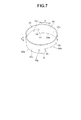
- Fig. 7 is an enlarged perspective view showing the annular member in Fig. 3 .
- Fig. 8 is an exploded perspective view showing the annular member in Fig. 7 and an upper movable disk.
- Fig. 9 is a view showing a state in which the upper movable disk is fitted to the annular member in Fig. 8 as viewed from the IX direction in Fig. 8 .
- Fig. 10 is an enlarged plan view showing the upper movable disk or the lower movable disk in Fig. 3 .
- Fig. 11 is an enlarged perspective view showing a state in which the cam member, the annular member, the two movable disks, the fixed disk, the support plate, and the fixing lever in Fig. 3 are assembled together.
- Fig. 12 is a partial sectional view of the bending operation apparatus taken along the XII-XII line in Fig. 2 .
- Fig. 13 is a partial sectional view of the bending operation apparatus taken along the XIII-XIII line in Fig. 2 .
- Fig. 14 is a partial sectional view showing a third position for the annular member in Fig. 2 along with a first position for the two movable disks.
- Fig. 15 is a partial sectional view showing a fourth position for the annular member in Fig. 2 along with a second position for the two movable disks.
- the configuration of the bending operation apparatus 100 is described below by citing an exemplary configuration relating to the bending operation knob 4 and the fixing lever 5.
- the bending operation knob 4 is locked in an unfixed state to top portions 18c which serve as one end portion, separated from the operation portion 3 in an axial direction A, of a cylindrical pivoting shaft 18 provided by being extended along the axial direction A that is a direction substantially orthogonal to the inserting direction S from the inside of the operation portion 3.
- the bending operation knob 4 is rotatable in a direction R1 or R2 (see Fig. 3 for both) of the pivoting direction R along with the pivoting shaft 18. Note that the description of the structure of locking the bending operation knob 4 to the top portions 18c is omitted because such structure is well-known.
- the bending operation knob 4 may be fixed to the top portions 18c.
- a chain (not shown) for bending the bending portion 2w is wound around the sprocket 19.
- the pivoting shaft 18 that is locked to the bending operation knob 4 in an unfixed state is also rotated in the same direction as that of the bending operation knob 4, and the sprocket 19 is also rotated in the same direction, so that pulling one of the sides of the chain causes the bending portion 2w to bend in an up or down direction.
- the configuration is not limited to the combination of the sprocket 19 and the chain, but may be a configuration in which the lower end of the pivoting shaft 18 is fitted to a pulley, and a wire wound around the pulley is pulled as the pulley is rotated.
- a cylindrical fixation shaft 10 extended along the axial direction A from the inside of the operation portion 3 is provided such that an upper end side which is an end portion separated from the operation portion 3 is inserted in a space 4i inside the bending operation knob 4.
- the fixation shaft 10 is formed along the axial direction A so as to have a polygonal sectional shape, a rectangular shape, for example, in the inserting direction S orthogonal to the axial direction A.
- the fixation shaft 10 is fixed to a sheathing member 3g of the operation portion 3 via an O-shaped ring or the like, and is located coaxially with the pivoting shaft 18 having a predetermined space in the radial direction K with respect to the pivoting shaft 18, and thereby the fixation shaft 10 is irrotational with respect to the pivoting shaft 18.
- the fixing lever 5 is in contact with an outer circumference of the fixation shaft 10 so as to be pivotable in the pivoting direction R via O-shaped rings 21 or the like, the fixing lever 5 being located in the space 4i inside the bending operation knob 4 and formed of a resin material, for example.
- an inner circumferential surface of a ring-shaped portion 5b of the fixing lever 5 constituted of a grasping portion 5r and the ring-shaped portion 5b is in contact with an outer circumference of the fixation shaft 10 pivotably in the pivoting direction R via the O-shaped rings 21 or the like.
- an outer circumference of the ring-shaped portion 5b of the fixing lever 5 is in contact with an inner circumferential surface of the support plate 23 located in the space 4i inside the bending operation knob 4 via an O-shaped ring 22 or the like.
- An outer circumferential surface of the support plate 23 is in contact with an inner circumferential surface 4n of the bending operation knob 4 via an O-shaped ring 24 or the like.
- the cam member 15 which is located in the space 4i inside the bending operation knob 4 and is formed of a metal material, for example, is located coaxially with the fixing lever 5 in the axial direction A on an upper surface 4u side with respect to the ring-shaped portion 5b of the fixing lever 5.
- the main part of the cam member 15 includes a ring-shaped base portion 15b and two protruding portions 15t that are each protruded in an inverted-L-shape toward the upper surface 4u side in the axial direction A from the base portion 15b so as to face each other with respect to the axial direction A.
- the cam member 15 is fixed to the fixing lever 5 by a plurality of convex portions 15p protruded inward in the radial direction K from the base portion 15b being respectively fitted to a plurality of concave portions 5m formed on a surface on the cam member 15 side of the ring-shaped portion 5b of the fixing lever 5.
- the cam member 15 is pivotable in the direction R1 or R2 in the pivoting direction R along with the fixing lever 5 by fitting of the convex portions 15p to the concave portions 5m.
- the fixing lever 5 performs a pivoting operation for the cam member 15. Therefore, the cam member 15 is pivotable separately from the pivoting of the pivoting shaft 18.
- the main part of the protruding portions 15t of the cam member 15 includes raised portions 15t1 protruded toward the upper surface 4u side in the axial direction A, transverse portions 15t2 extended in a circular arc shape along the pivoting direction R in the direction R2 from protruding ends of the raised portions 15t1, and step portions 15t3 located on the direction R1 side of the raised portions 15t1.
- cam grooves 15c are formed in the protruding portions 15t along the pivoting direction R between the base portion 15b and the transverse portions 15t2 in the axial direction A.
- the cam grooves 15c are formed to have inclined surfaces or circular-arc shaped surfaces such that a groove gap in the axial direction A decreases from m2 to m1 that is smaller than m2 (m2 > m1) toward the direction R1.
- cutouts 15be are formed in the base portion 15b of the cam member 15 so as to penetrate the base portion 15b in the axial direction A and have a predetermined length along the pivoting direction R respectively at positions which are symmetrical about a pivoting center of pivoting shaft 18, specifically, at positions facing the respective cam grooves 15c in the axial direction A.
- the movable disks 11 and 12 are formed to have the same shape and the same size.
- the movable disks 11, 12 are formed through-holes 11k, 12k that penetrate in the axial direction A, having an outer shape substantially equal to an outer shape of the fixation shaft 10, and a polygonal shape, for example, a rectangular shape, as seen in a plan view from the upper surface 4u side.
- the movable disks 11, 12 are fixed to the fixation shaft 10 inserted through the through-holes 11k, 12k.
- the through-hole 11k of the movable disk 11 is formed in the same position as that of the through-hole 12k of the movable disk 12. That is, when the movable disk 11 and the movable disk 12 are superposed on each other, the through-holes 11k and 12k are superimposed each other. The positioning of the movable disks 11 and 12 in the pivoting direction R will be described later.
- a fixed disk 14 which is located coaxially with the two movable disks 11, 12 in the axial direction A and is located in the space 4i inside the bending operation knob 4.
- the fixed disk 14 is in contact with the inner circumferential surface 4n of the bending operation knob 4 such that O-shaped rings 25 provided on an outer circumferential surface of the fixed disk 14 are set to have a shape and a pressing amount so as to generate a proper bending holding force with respect to the bending operation knob 4.
- the fixed disk 14 also has a flange portion 14f that is sandwiched by the two movable disks 11, 12 in the axial direction A in the second position (see Fig. 6 ) to be described later.
- the O-shaped rings 25 may be discontinuously in contact with the inner circumferential surface 4n.
- the fixed disk 14 pivots along with the bending operation knob 4 in the first position (see Fig. 5 ) to be described later.
- two slits 11s and two slits 12s having a partial circular arc shape in the pivoting direction R are respectively formed in the respective disks 11, 12 so as to penetrate in the axial direction A, to be symmetrical about a pivoting center of the pivoting shaft 18, and to partially surround the respective through-holes 11k, 12k.
- the slits 11s of the movable disk 11 are formed in the same positions as those of the slits 12s of the movable disk 12. That is, when the movable disks 11 and 12 are superposed on each other, the respective slits 11s and 12s are superimposed each other.
- the slits 11s, 12s are formed to be precisely positioned on the basis of the positions of the through-holes 11k, 12k.
- the protruding portions 15t of the cam member 15 penetrate through the slits 11s, 12s to be movable in the direction R1 or R2 in the pivoting direction R separately from the pivoting shaft 18. That is, in a state where the protruding portions 15t of the cam member 15 have penetrated through the slits 11s, 12s, parts of the two movable disks 11, 12 are fitted in the cam grooves 15c.
- the protruding portions 15t are movable in the pivoting direction R in the slits 11s, 12s between the position where the step portions 15t3 come into contact with opening end portions 12sk and the position where end portions 11sw, 12sw (see Figs. 5 and 6 ) of the two movable disks 11, 12 come into contact with end portions 15ct of the cam grooves 15c.
- the two movable disks 11, 12 are separated from each other by the first gap d1 in the axial direction A as shown in Fig. 5 .
- the position in which the movable disks 11, 12 are separated from each other by the first gap d1 in the axial direction A will be indicated as the first position.
- the distal end side of the transverse portions 15t2 in the direction R2 is in contact with a top surface of the movable disk 11, and therefore, the protruding portions 15t do not come off the respective slits 11s, 12s toward the operation portion 3 side.
- cam grooves 15c are formed in the protruding portions 15t in the pivoting direction R.
- the movable disk 11 With this movement, the movable disk 11 is guided by the inclined surfaces or the circular-arc shaped surfaces formed on the cam grooves 15c, and the rotational force is converted into the force in the axial direction A, whereby the movable disk 11 moves to the second position where the movable disk 11 is separated from the movable disk 12 by the second gap d2 that is shorter than the first gap d1 (d2 ⁇ d1) in the axial direction A as shown in Fig. 6 .
- the cam grooves 15c have a shape that causes the movable disk 11 to move from the first position to the second position as the cam member 15 is rotated in the direction R2.
- the cam grooves 15c have a function of converting the rotational force into the force in the axial direction A and moving the movable disk 11 from the first position to the second position as the cam member 15 is rotated in the direction R2.
- the respective slits 11s, 12s are penetrated through along the axial direction A by penetrating portions 30k of the annular member 30 located inside the respective protruding portions 15t in the radial direction K and located coaxially with the respective movable disks 11, 12 in the axial direction A.
- the annular member 30 is formed of a metal material such as elastic stainless steel, for example.
- the annular member 30 has a ring shape with a predetermined length along the axial direction A.
- respective inverted-concave-shaped clearances 30h are formed in positions where the annular member 30 are cut out along the pivoting direction R by a predetermined range so as to have openings on the operation portion 3 side.
- the penetrating portions 30k are respectively formed to have a predetermined length of circular-arc in the pivoting direction R, a predetermined length in the axial direction A, and a shape to fit in the slits 11s, 12s.
- the penetrating portions 30k penetrate the slits 11s, 12s in the axial direction A inside the respective protruding portions 15t in the radial direction K, and are formed to have the same length of circular-arc as the length of circular-arc of the respective slits 11s, 12s in the pivoting direction R.
- both end portions 30km of the respective penetrating portions 30k in the pivoting direction R are formed to have a length with which the penetrating portions 30k contact the respective end portions 11sk, 11sw, 12sk and 12sw of the respective slits 11s, 12 (see Figs. 3 and 10 for all of these elements) after the penetrating portions 30k penetrate the respective slits 11s, 12s. With this formation, the penetrating portions 30k accurately penetrate the respective slits 11s, 12s.
- the movable disk 12 is fixed on the outer circumference of the fixation shaft 10 in a state where the movable disk 12 is precisely positioned with respect to the movable disk 11 in the pivoting direction R. That is, when the movable disks 11 and 12 are superposed each other, the respective through-holes 11k, 12k are superimposed in the precise position and the respective slits 11s, 12s are also superimposed each other in the precise position.
- projecting portions 33 to which the movable disk 11 is locked are formed at the both end portions 30km of the penetrating portions 30k.
- the main part of the projecting portions 33 includes inclined surface portions 33s protruded toward the clearances 30h side with respect to the end portions 30km, and placement portions 33p that are between top portions of the inclined surface portions 33s and the end portions 30km, and are perpendicular to the axial direction A.
- the movable disk 11 When the the slits 11s are penetrated by the penetrating portions 30k, the movable disk 11 is fixed to the annular member 30 by the respective end portions 11sk, 11sw of the slits 11s going through the inclined surface portions 33s from the operation portion 3 side, and a bottom face 11x of the movable disk 11 being fitted so as to be placed on the placement portions 33p as shown in Fig. 9 .
- the annular member 30 is movable between a third position shown in Fig. 14 corresponding to the first position and the fourth position shown in Fig. 15 corresponding to the second position in the axial direction A, integrally with the movable disk 11 movable between the first position shown in Fig. 5 and the second position shown in Fig. 6 , as the cam member 15 is pivoted in the pivoting direction R as described above.
- escape portions 11n, 12n protruded inward in the radial direction K are formed to cause the both end portions 30km of the penetrating portions 30k and the projecting portions 33 to escape inward in the radial direction K when the penetrating portions 30k penetrate through slits 11s, 12s.
- the escape portions 11n, 12n are designed to, when the movable disk 11 is to be locked to the projecting portions 33 of the annular member 30, allow the both end portions 30km and the projecting portions 33 of the penetrating portions 30k of the annular member 30 to slightly elastically deform and escape inward in the radial direction, to permit easy flexure of the penetrating portions 30k in the slits 11s, thereby facilitating passage of the inclined surface portions 33s through the slits 11s and locking of the movable disk 11 to the projecting portions 33.
- the escape portions 11n, 12n absorb the inward flexure in the radial direction K of the penetrating portions 30k in the slits 11s, 12s.
- ridge portions 32 protruded outward in the radial direction K are formed on the outer circumferential surface 30g of the annular member 30 except the region of the penetrating portions 30k in positions symmetrical about the pivoting center of the pivoting shaft 18.
- the ridge portions 32 are designed to apply a resistance force to the pivoting of the cam member 15, thereby preventing an unintended movement of the cam member 15 in the pivoting direction R in the first position or the second position.
- the locking portions 15tv When the locking portions 15tv are moved in the pivoting direction R, the locking portions 15tv get over the ridge portions 32 to give a click feel to the operator, whereby the operator can easily recognize through the fixing lever 5 to which the cam member 15 is fixed that the movable disks 11, 12 have moved from the first position to the second position, or from the second position to the first position. That is, the ridge portions 32 notify the operator of completion of the movement of the movable disks 11, 12 with the click feel.
- step portions 31 protruded toward the operation portion 3 side are formed in positions on bottom portions 30kt of the penetrating portions 30k, the bottom portions 30kt being on an opposite side of the top portions 18c, the positions being close to the end portions 30km that are close to the inclined surfaces on the direction R1 side of the ridge portions 32.
- the step portions 31 are not in contact with the base portion 15b by fitting in the cutouts 15be formed at the base portion 15b of the cam member 15 shown in Figs. 4 and 12 .
- the step portions 31 allow the position for the movable disks 11, 12 to be changed from the second position to the first position by coming into contact with the base portion 15b as shown in Fig. 14 in the third position for the annular member 30 which corresponds to the first position shown in Fig. 5 , as the cam member 15 is rotated from the second position in the direction R1 which is the other rotation direction.
- the position for the movable disks 11, 12 is changed from the second position to the first position. That is, the step portions 31 enable the position for the movable disks 11, 12 to change from the second position to the first position.
- the pivoting shaft 18 fixed to the bending operation knob 4 and the sprocket 19 also rotates in the direction R1 or R2, which causes one of the sides of the chain wound around the sprocket 19 to be pulled, whereby the bending portion 2w is bent in the up or down direction.
- the fixation shaft 10 does not pivot since the fixation shaft 10 is unpivotable with respect to the pivoting shaft 18.
- the cam member 15 is prevented from being unintentionally rotated toward the direction R2 side since the locking portions 15tv of the transverse portions 15t2 of the protruding portions 15t of the cam member 15 are blocked by the inclined surfaces on the direction R1 side of the ridge portions 32 on the outer circumferential surface 30g of the annular member 30. That is, the first position of the movable disk 11, 12 is fixed.
- the cam member 15 also rotates in the direction R2. Note that at this time, the fixation shaft 10, the two movable disks 11, 12 fixed to the fixation shaft 10, and the annular member 30 do not rotate in the direction R2.
- the protruding portions 15t of the cam member 15 move in the slits 11s, 12s in the direction R2 until the end portions 11sw, 12sw of the slits 11s, 12s of the movable disks 11, 12 come into contact with the end portions 15ct of the cam grooves 15c.
- the movable disk 11 is guided toward the movable disk 12 through the inclined surfaces or the circular-arc shaped surfaces formed on the cam grooves 15c, the rotational force is converted into the force in the axial direction A, and the movable disk 11 is moved from the first position shown in Fig. 5 to the second position where the movable disk 11 is separated from the movable disk 12 by the second gap d2 shorter than the first gap d1 in the axial direction A as shown in Fig. 6 .
- the step portions 31 formed at the bottom portions 30kt of the penetrating portions 30k of the annular member 30 to which the movable disk 11 is fixed are fitted in the cutouts 15be of the base portion 15b of the cam member 15, as shown in Fig. 15 .
- the annular member 30 also moves from the third position shown in Fig. 14 to the fourth position shown in Fig. 15 .
- the cam member 15 rotates in the direction R2 to cause the locking portions 15tv of the transverse portions 15t2 of the protruding portions 15t of the cam member 15 to get over the ridge portions 32 on the outer circumferential surface 30g of the annular member 30. This gives the operator the click feel through the fixing lever 5 and notifies the operator of the completion of the rotation of the cam member 15 in the direction R2.
- the locking portions 15tv are locked by the inclined surfaces on the direction R2 side of the ridge portions 32, thereby preventing the cam member 15 from being unintentionally rotated in the direction R1. That is, the second position of the movable disks 11, 12 is fixed.
- the step portions 31 of the bottom portions 30kt of the penetrating portions 30k of the annular member 30 get on the base portion 15b from cutouts 15be as shown in Fig. 14 .
- the movable disk 12 remains in contact with a bottom face of the fixed disk 14.
- the part of the fixed disk 14 that contacts the movable disk 11 is constituted of a member made of rubber or the like whose frictional force becomes greater due to the contact with the movable disk. Therefore, when the movable disk 11 is not completely separated from the fixed disk 14, there is a possibility that the frictional force is applied by the movable disk 11, and consequently, the frictional force is applied to the inner circumferential surface 4n through the fixed disk 14 even in the first position.
- the part of the fixed disk 14 that comes into contact with the movable disk 12 is formed of a resin material or the like, even if the part is in contact with the movable disk 12, the frictional force would not be applied through the fixed disk 14 to the inner circumferential surface 4n since the frictional force from the movable disk 12 to the fixed disk 14 is small.
- the bending operation knob 6 and the fixing knob 7 also have the same actions as those mentioned above.
- the present embodiment has described as follows.
- the slits 11s, 12s of the movable disks 11, 12 are penetrated in the axial direction by the penetrating portions 30k of the annular member 30 on an inner side in the radial direction K with respect to the protruding portions 15t of the cam member 15.
- the movable disk 11 is fixed to the annular member 30, and thereby the annular member 30 is movable along with the movable disk 11 in the axial direction A.
- step portions 31 are formed at the bottom portions 30kt of the penetrating portions 30k of the annular member 30 so as to fit in the cutouts 15be of the base portion 15b of the cam member 15 in the fourth position for the annular member 30 corresponding to the second position of the movable disks 11, 12, and get on and come into contact with the base portion 15b of the cam member 15 in the third position for the annular member 30 corresponding to the first position for the movable disks 11, 12.
- the movable disk 11 moves from the second position to the first position by the step portions 31 getting on the base portion 15b from the cutouts 15be.
- the bending operation apparatus 100 for the endoscope having the configuration that can easily and surely prevent a resistance force from being applied to the pivoting of the bending operation knob 4 after the fixation of the pivoting position of the bending operation knob 4 is released, and provide the endoscope 1 including the bending operation apparatus.
- the present embodiment may also have a configuration in which a spring is additionally provided in the space in the axial direction A between the movable disk 11 and 12, as in conventional arts, to more surely separate the movable disk 11 from the fixed disk 14 by the force of the spring in addition to the step portions 31 getting on the base portion 15b.
- the provision of the spring enables to more surely separate not only the movable disk 11 but also the movable disk 12 from the fixed disk 14, and to more surely fix the position of the movable disk 12 in the axial direction A in the first position.
- the present embodiment which has described that the movable disk 11 is fixed to the annular member 30, is not limited to this configuration, but the movable disk 11 may be formed integrally with the annular member 30.
- Fig. 16 is a view showing the modification example of the shape of the cam grooves formed in the protruding portions in the cam member in Fig. 4 .
- the cam grooves 15c are formed between the transverse portions 15t2 and the base portion 15b, having the inclined surfaces or the circular-arc shaped surfaces, such that the groove gaps in the axial direction A decrease from m2 to m1 that is smaller than m2 (m2 > m1) toward the direction R1 in the protruding portions 15t as shown in Fig. 5 .
- cam grooves 15c have a shape that allows the movable disk 11 to move from the first position to the second position as the cam member 15 is rotated in the direction R2. It is further described that the cam grooves 15c have a function of converting the rotational force into the force in the axial direction A and causing the movable disk 11 to move from the first position to the second position as the cam member 15 is rotated in the direction R2.
- cam grooves 15c may be formed into a shape that causes not only the movable disk 11 but also both the movable disks 11, 12 to move from the first position to the second position.
- the cam grooves 15c may have a shape that causes both the movable disks 11, 12 to move from the first position to the second position as the cam member 15 is rotated in the direction R2 by being formed to have the inclined surfaces or the circular-arc shaped surfaces with respect to both the transverse portions 15t2 and the base portion 15b such that the groove gaps in the axial direction A decreases from m3 that is larger than m2 to m1 that is smaller than m3 (m3 > m1) toward the direction R1.
- the cam grooves 15c have the function of converting the rotational force into the force in the axial direction A and causing both the movable disks 11, 12 to move from the first position to the second position as the cam member 15 is rotated in the direction R2.
- Such a configuration also allows the movable disk 12 to be surely separated from the fixed disk 14 in the first position.
Landscapes
- Health & Medical Sciences (AREA)
- Life Sciences & Earth Sciences (AREA)
- Surgery (AREA)
- Biomedical Technology (AREA)
- Medical Informatics (AREA)
- Optics & Photonics (AREA)
- Pathology (AREA)
- Radiology & Medical Imaging (AREA)
- Biophysics (AREA)
- Engineering & Computer Science (AREA)
- Physics & Mathematics (AREA)
- Heart & Thoracic Surgery (AREA)
- Nuclear Medicine, Radiotherapy & Molecular Imaging (AREA)
- Molecular Biology (AREA)
- Animal Behavior & Ethology (AREA)
- General Health & Medical Sciences (AREA)
- Public Health (AREA)
- Veterinary Medicine (AREA)
- Endoscopes (AREA)
- Instruments For Viewing The Inside Of Hollow Bodies (AREA)
Abstract
Description
- The present invention relates to a bending operation apparatus for an endoscope that is provided in an operation portion of the endoscope and causes a bending portion of an insertion portion of the endoscope to bend, and to the endoscope including the bending operation apparatus.
- In recent years, endoscopes have been widely used in the medical field and the industrial field. The endoscope for use in the medical field is capable of observing organs in a body cavity with an elongated insertion portion inserted into the body cavity that is a subject. The endoscope for use in the medical field is also capable of performing various treatments by using as necessary a treatment instrument inserted into an insertion channel included in the endoscope.
- With the endoscope for use in the industrial field, the elongated insertion portion of the endoscope can be inserted into an object such as a jet engine and pipes in a factory, thereby allowing to perform inspections such as observations of scratches and corrosions of a region to be inspected in the object, and various treatments with respect to the region to be inspected in the object.
- A configuration is well-known in which a bending portion bendable in plural directions is provided to the insertion portion of the endoscope. The bending portion improves the advanceability of the insertion portion in a crooked portion in a duct and renders variable the observation direction of an observation optical system provided at a distal end portion located on a distal end side in an inserting direction with respect to the bending portion (hereinafter referred to as "distal end side"), in the insertion portion.
- The bending portion provided at the insertion portion of the endoscope is typically configured to be bendable in four directions, for example, up, down, right and left directions, with a plurality of bending pieces being connected along the inserting direction of the insertion portion. The bending portion is bendable in any of the up, down, right and left directions by a bending operation apparatus provided in an operation portion pulling any of four wires which are inserted through in the insertion portion and which have distal ends in the inserting direction (hereinafter referred to as "distal ends") fixed to a bending piece located on the distal-most end side of the bending pieces.
- Specifically, the bending portion has a configuration in which an up-and-down bending sprocket provided in the operation portion is pivoted through a pivoting operation by a bending operation knob for up-and-down bending provided in the operation portion, to pull an upside chain part or a downside chain part of an up and down bending chain wound around the sprocket, thereby pulling an upper or lower wire so that the the bending portion is bent in either an up or down direction.
- Further, the bending portion has a configuration in which a right-and-left bending sprocket provided in the operation portion is pivoted through a pivoting operation by a bending operation knob for right-and-left bending provided in the operation portion, to pull a right chain part or a left chain part of a right-and-left bending chain wound around the sprocket, thereby pulling a right or left wire, so that the bending portion is bent in either a right or left direction.
- A configuration is also well-known in which the operation portion is provided with an up-and-down bending lock lever that fixes a bending angle of the bending portion that is bent in an up or down direction by the pivoting operation of the bending operation knob for up-and-down bending, namely, fixes the pivoting position of the bending operation knob for up-and-down bending. A configuration is also well-known in which the operation portion is provided with a right-and-left lock knob that fixes the bending angle of the bending portion that is bent in a right or left direction by the pivoting operation of a bending operation knob for right-and-left bending, namely, fixes the pivoting position of the bending operation knob for right-and-left bending. The configurations of the lock knob are disclosed in Japanese Patent Application Laid-Open Publication No.
10-286220 - Japanese Patent Application Laid-Open Publication No.
10-286220 - When the pivoting position of the bending operation knob for up-and-down bending is fixed using the configuration disclosed in Japanese Patent Application Laid-Open Publication No.
10-286220 - Note that in Japanese Patent Application Laid-Open Publication No.
10-286220 - However, in the configuration disclosed in Japanese Patent Application Laid-Open Publication No.
10-286220 - Further, in order to elastically deform the friction member, it is necessary to sandwich the friction member between the fixed member and the movable member with a large force, and therefore there is a problem that the lock lever or the lock knob for rotating the movable member has to be rotated with a large force.
- Furthermore, the mechanism for sandwiching the friction member by two members using the screw mechanism involves a problem that the bending operation apparatus is made large in size.
- In view of the foregoing problems, such a configuration for a small bending operation apparatus may also be possible in which the pivoting position of the bending operation knob can be properly fixed with a weak force without a positional variation every time the bending operation knob is used, by using cam grooves instead of the screw mechanism to move two movable disks so as to have a small gap between the movable disks, so that the movable disks sandwich a fixed disk that applies a frictional force to the pivoting of the bending operation knob.
- Besides, in such a bending operation apparatus, a configuration using a spring member can be conceived for separating the two movable disks from the fixed disk, but in a case where the bending operation apparatus is reduced in size, a distance between the two movable disks has to be set narrow to a degree not coming into contact with the fixed disk in a state of being separated from each other. With this situation, there have been not only a problem that it is difficult to assemble the spring between the two movable disks but also a problem that a separating action of the two movable disks by the spring is not stable since only a small spring can be assembled.
- Therefore, there has been a problem that a resistance force is added to the rotation of the bending operation knob even in a state where the fixing of the rotational position of the bending operation knob is released by separating the two movable disks from the fixed disk in the configuration where the separation of the movable disks is carried out only by the spring member since, if the spring action is weak, the two movable disks are not sufficiently separated from the fixed disk and a frictional resistance is caused in a case where the movable disks remain in contact with the fixed disk.
- The present invention has been made in view of the foregoing problems and an object of the present invention is to provide a bending operation apparatus for an endoscope and an endoscope including the bending operation apparatus which are provided with configurations capable of simply and securely preventing addition of a resistance force to rotation of a bending operation knob after releasing of fixing of a rotational position of the bending operation knob.
- A bending operation apparatus for an endoscope according to one aspect of the present invention includes: a pivoting shaft; a bending operation knob that is pivotable with the pivoting shaft by being engaged with one end portion of the pivoting shaft in an axial direction thereof and performs a bending operation of a bending portion of the endoscope; a fixation shaft that is provided coaxially with the pivoting shaft and irrotational with respect to the pivoting shaft; two movable disks that are fixed to an outer circumference of the fixation shaft in a radial direction thereof and respectively provided with slits formed to penetrate in the axial direction, the two movable disks being locatable, with at least one of the two movable disks being moved, between a first position in which the two movable disks are separated by a first gap in the axial direction and a second position in which the two movable disks are separated by a second gap that is shorter than the first gap in the axial direction; a fixed disk that is provided coaxially with the two movable disks to be in contact with an inner circumferential surface of the bending operation knob, the fixed disk being sandwiched by the two movable disks in the second position to apply a frictional force to pivoting of the bending operation knob; a cam member that is provided coaxially with the two movable disks and has a protruding portion which penetrates the slits in the axial direction and is movable in the slits in a pivoting direction of the pivoting shaft, the cam member being pivotable in the pivoting direction separately with the pivoting of the pivoting shaft and causing at least one of the two movable disks to move in the axial direction by a cam groove formed at the protruding portion in accordance with pivoting in one direction to change position of the two movable disks from the first position to the second position; and an annular member that is provided coaxially with the two movable disks and has a penetrating portion which penetrates the slits in the axial direction on an inner side in the radial direction with respect to the protruding portion, the annular member being movable integrally with the fixed movable disk between a third position and a fourth position in the axial direction with one of the two movable disks on a side of the one end of the pivoting shaft being fixed, wherein a step portion is formed at other end portion opposite to the one end portion in the axial direction in the penetrating portion, the step portion being not in contact with a base portion facing the other end portion of the annular member in the cam member at the fourth position where the two movable disks are located at the second position and coming in contact with the base portion at the third position in accordance with pivoting of the cam member in other direction to thereby change the position of the two movable disks from the second position to the first position.
- Further, an endoscope including the bending operation apparatus according to one aspect of the present invention includes the bending operation apparatus for the endoscope according to the one aspect.
-
-
Fig. 1 is a view showing an external appearance of an endoscope having an operation portion including a bending operation apparatus according to the present embodiment. -
Fig. 2 is a partial sectional view showing a configuration of the bending operation apparatus provided in the operation portion of the endoscope inFig. 1 . -
Fig. 3 is an exploded perspective view showing a part of the configuration of the bending operation apparatus inFig. 2 . -
Fig. 4 is an enlarged perspective view showing the cam member inFig. 3 . -
Fig. 5 is a view schematically showing a state in which parts of two movable disks are assembled so as to be fitted in cam grooves provided in protruding portions of the cam member inFig. 4 , having a first gap between the two movable disks. -
Fig. 6 is a view schematically showing a state in which the two movable disks inFig. 5 are moved to a position where the disks have a second gap by the cam grooves as the cam member is rotated. -
Fig. 7 is an enlarged perspective view showing the annular member inFig. 3 . -
Fig. 8 is an exploded perspective view showing the annular member inFig. 7 and an upper movable disk. -
Fig. 9 is a view showing a state in which the upper movable disk is fitted to the annular member inFig. 8 as viewed from the IX direction inFig. 8 . -
Fig. 10 is an enlarged plan view showing the upper movable disk or the lower movable disk inFig. 3 . -
Fig. 11 is an enlarged perspective view showing a state in which the cam member, the annular member, the two movable disks, the fixed disk, the support plate, and the fixing lever inFig. 3 are assembled together. -
Fig. 12 is a partial sectional view of the bending operation apparatus taken along the XII-XII line inFig. 2 . -
Fig. 13 is a partial sectional view of the bending operation apparatus taken along the XIII-XIII line inFig. 2 . -
Fig. 14 is a partial sectional view showing a third position for the annular member inFig. 2 along with a first position for the two movable disks. -
Fig. 15 is a partial sectional view showing a fourth position for the annular member inFig. 2 along with a second position for the two movable disks. -
Fig. 16 is a view showing a modification example of the shape of the cam grooves formed at protruding portions of the cam member inFig. 4 . - Hereinafter, an embodiment of the present invention will be described with reference to the drawings. It should be noted that the drawings are schematic and relations between thicknesses and widths of respective members, ratios of the thicknesses of the respective members, and the like are different from real ones. It goes without saying that different drawings contain portions of elements having different relations and ratios of dimensions.
-
Fig. 1 is a view showing an external appearance of an endoscope having an operation portion including a bending operation apparatus according to the present embodiment. - As shown in
Fig. 1 , the main part of the endoscope 1 includes aninsertion portion 2 to be inserted into a subject, an operation portion 3 connected on a proximal end side in an inserting direction S of theinsertion portion 2, auniversal cord 8 extended from the operation portion 3, and a connector 9 provided at an extended end of theuniversal cord 8. The endoscope 1 is electrically connected with external apparatuses such as a control apparatus and a lighting apparatus via the connector 9. - The operation portion 3 is provided with an up-and-down bending operation knob (hereinafter referred to as "bending operation knob") 4 that causes a
bending portion 2w to be described later, of theinsertion portion 2 to bend in an up-and-down direction, and a right-and-left bending operation knob (hereinafter referred to as "bending operation knob") 6 that causes thebending portion 2w to bend in a right-and-left direction. - Furthermore, the operation portion 3 is provided with a
fixing lever 5 that fixes a pivoting position of thebending operation knob 4 and afixing knob 7 that fixes a pivoting position of thebending operation knob 6. - Note that the
bending operation knob 4, thefixing lever 5, thebending operation knob 6, and thefixing knob 7 constitute a bending operation apparatus 100 (seeFig. 2 ) to be described later according to the present embodiment, together with other members provided in the operation portion 3. - The
insertion portion 2 is constituted of adistal end portion 2s, thebending portion 2w, and aflexible tube portion 2k, and formed to be elongate along the inserting direction S. - In the
distal end portion 2s are provided an image pickup unit (not shown) for observing the inside of a subject, an illumination unit that illuminates the inside of the subject, and the like. - Further, the
bending portion 2w renders variable the observation direction of the image pickup unit provided at thedistal end portion 2s and improves insertability of thedistal end portion 2s into the subject, by being bent in four directions, for example, up, down, right and left directions, through pivoting operations of thebending operation knob 4 and thebending operation knob 6. Furthermore, on a proximal end side of thebending portion 2w, theflexible tube portion 2k is connectively provided. - Next, a configuration of the
bending operation apparatus 100 for the endoscope provided in the operation portion 3 will be described with reference toFigs. 2 to 15 . -
Fig. 2 is a partial sectional view showing the configuration of the bending operation apparatus provided in the operation portion of the endoscope inFig. 1 .Fig. 3 is an exploded perspective view showing a part of the configuration of the bending operation apparatus inFig. 2 . -
Fig. 4 is an enlarged perspective view showing the cam member inFig. 3 .Fig. 5 is a view schematically showing a state in which parts of two movable disks are assembled so as to be fitted in cam grooves provided in protruding portions of the cam member inFig. 4 , having a first gap between the two movable disks.Fig. 6 is a view schematically showing a state in which the two movable disks inFig. 5 are moved to a position where the disks have a second gap by the cam grooves as the cam member is rotated. -
Fig. 7 is an enlarged perspective view showing the annular member inFig. 3 .Fig. 8 is an exploded perspective view showing the annular member inFig. 7 and an upper movable disk.Fig. 9 is a view showing a state in which the upper movable disk is fitted to the annular member inFig. 8 as viewed from the IX direction inFig. 8 . -
Fig. 10 is an enlarged plan view showing the upper movable disk or the lower movable disk inFig. 3 .Fig. 11 is an enlarged perspective view showing a state in which the cam member, the annular member, the two movable disks, the fixed disk, the support plate, and the fixing lever inFig. 3 are assembled together. -
Fig. 12 is a partial sectional view of the bending operation apparatus taken along the XII-XII line inFig. 2 .Fig. 13 is a partial sectional view of the bending operation apparatus taken along the XIII-XIII line inFig. 2 .Fig. 14 is a partial sectional view showing a third position for the annular member inFig. 2 along with a first position for the two movable disks.Fig. 15 is a partial sectional view showing a fourth position for the annular member inFig. 2 along with a second position for the two movable disks. - Note that the configuration of the bending
operation apparatus 100 is described below by citing an exemplary configuration relating to the bendingoperation knob 4 and the fixinglever 5. - As shown in
Fig. 2 , the bendingoperation knob 4 is locked in an unfixed state totop portions 18c which serve as one end portion, separated from the operation portion 3 in an axial direction A, of acylindrical pivoting shaft 18 provided by being extended along the axial direction A that is a direction substantially orthogonal to the inserting direction S from the inside of the operation portion 3. The bendingoperation knob 4 is rotatable in a direction R1 or R2 (seeFig. 3 for both) of the pivoting direction R along with the pivotingshaft 18. Note that the description of the structure of locking the bendingoperation knob 4 to thetop portions 18c is omitted because such structure is well-known. The bendingoperation knob 4 may be fixed to thetop portions 18c. - A lower end which is another end portion of the pivoting
shaft 18 in the axial direction A, located inside the operation portion 3, is fitted to thesprocket 19 provided inside the operation portion 3. A chain (not shown) for bending the bendingportion 2w is wound around thesprocket 19. - Thus, when the bending
operation knob 4 is rotationally operated in the direction R1 or R2, the pivotingshaft 18 that is locked to the bendingoperation knob 4 in an unfixed state is also rotated in the same direction as that of the bendingoperation knob 4, and thesprocket 19 is also rotated in the same direction, so that pulling one of the sides of the chain causes the bendingportion 2w to bend in an up or down direction. - Note that the configuration is not limited to the combination of the
sprocket 19 and the chain, but may be a configuration in which the lower end of the pivotingshaft 18 is fitted to a pulley, and a wire wound around the pulley is pulled as the pulley is rotated. - Around an outer circumference in a radial direction K of the pivoting
shaft 18, acylindrical fixation shaft 10 extended along the axial direction A from the inside of the operation portion 3 is provided such that an upper end side which is an end portion separated from the operation portion 3 is inserted in aspace 4i inside the bendingoperation knob 4. Thefixation shaft 10 is formed along the axial direction A so as to have a polygonal sectional shape, a rectangular shape, for example, in the inserting direction S orthogonal to the axial direction A. - The
fixation shaft 10 is fixed to asheathing member 3g of the operation portion 3 via an O-shaped ring or the like, and is located coaxially with the pivotingshaft 18 having a predetermined space in the radial direction K with respect to the pivotingshaft 18, and thereby thefixation shaft 10 is irrotational with respect to the pivotingshaft 18. - Further, the fixing
lever 5 is in contact with an outer circumference of thefixation shaft 10 so as to be pivotable in the pivoting direction R via O-shapedrings 21 or the like, the fixinglever 5 being located in thespace 4i inside the bendingoperation knob 4 and formed of a resin material, for example. - Specifically, as shown in
Figs. 2 and3 , an inner circumferential surface of a ring-shapedportion 5b of the fixinglever 5 constituted of a graspingportion 5r and the ring-shapedportion 5b is in contact with an outer circumference of thefixation shaft 10 pivotably in the pivoting direction R via the O-shapedrings 21 or the like. - As shown in
Fig. 2 , an outer circumference of the ring-shapedportion 5b of the fixinglever 5 is in contact with an inner circumferential surface of thesupport plate 23 located in thespace 4i inside the bendingoperation knob 4 via an O-shapedring 22 or the like. An outer circumferential surface of thesupport plate 23 is in contact with an innercircumferential surface 4n of the bendingoperation knob 4 via an O-shapedring 24 or the like. - Around the outer circumference of the
fixation shaft 10, thecam member 15 which is located in thespace 4i inside the bendingoperation knob 4 and is formed of a metal material, for example, is located coaxially with the fixinglever 5 in the axial direction A on anupper surface 4u side with respect to the ring-shapedportion 5b of the fixinglever 5. - As shown in
Fig. 4 , the main part of thecam member 15 includes a ring-shapedbase portion 15b and two protrudingportions 15t that are each protruded in an inverted-L-shape toward theupper surface 4u side in the axial direction A from thebase portion 15b so as to face each other with respect to the axial direction A. - As shown in
Fig. 3 , thecam member 15 is fixed to the fixinglever 5 by a plurality ofconvex portions 15p protruded inward in the radial direction K from thebase portion 15b being respectively fitted to a plurality ofconcave portions 5m formed on a surface on thecam member 15 side of the ring-shapedportion 5b of the fixinglever 5. - That is, the
cam member 15 is pivotable in the direction R1 or R2 in the pivoting direction R along with the fixinglever 5 by fitting of theconvex portions 15p to theconcave portions 5m. In other words, the fixinglever 5 performs a pivoting operation for thecam member 15. Therefore, thecam member 15 is pivotable separately from the pivoting of the pivotingshaft 18. - As shown in
Fig. 4 , the main part of the protrudingportions 15t of thecam member 15 includes raised portions 15t1 protruded toward theupper surface 4u side in the axial direction A, transverse portions 15t2 extended in a circular arc shape along the pivoting direction R in the direction R2 from protruding ends of the raised portions 15t1, and step portions 15t3 located on the direction R1 side of the raised portions 15t1. - As shown in
Figs. 4 to 6 ,cam grooves 15c are formed in the protrudingportions 15t along the pivoting direction R between thebase portion 15b and the transverse portions 15t2 in the axial direction A. - As shown in
Fig. 5 , thecam grooves 15c are formed to have inclined surfaces or circular-arc shaped surfaces such that a groove gap in the axial direction A decreases from m2 to m1 that is smaller than m2 (m2 > m1) toward the direction R1. - Furthermore, as shown in
Figs. 4 and13 , extended ends on a direction R2 side of the transverse portions 15t2 of the protrudingportions 15t are bent in a crank shape, whereby locking portions 15tv are formed. - As shown in
Figs. 4 and12 , cutouts 15be are formed in thebase portion 15b of thecam member 15 so as to penetrate thebase portion 15b in the axial direction A and have a predetermined length along the pivoting direction R respectively at positions which are symmetrical about a pivoting center of pivotingshaft 18, specifically, at positions facing therespective cam grooves 15c in the axial direction A. - Returning to
Fig. 2 , on theupper surface 4u side with respect to thebase portion 15b of thecam member 15 in the outer circumference of thefixation shaft 10, an upper movable disk (hereinafter referred to as "movable disk") 11 on thetop portions 18c side and a lower movable disk (hereinafter referred to as "movable disk") 12 that are formed of, for example, a metal material, specifically, a hard material such as stainless steel, are fixed in parallel so as to be located coaxially with thecam member 15 in the axial direction A, in thespace 4i inside the bendingoperation knob 4. Note that themovable disks - Specifically, as shown in
Figs. 3 and10 , in themovable disks holes fixation shaft 10, and a polygonal shape, for example, a rectangular shape, as seen in a plan view from theupper surface 4u side. Themovable disks fixation shaft 10 inserted through the through-holes - The through-
hole 11k of themovable disk 11 is formed in the same position as that of the through-hole 12k of themovable disk 12. That is, when themovable disk 11 and themovable disk 12 are superposed on each other, the through-holes movable disks - Thus the
movable disks fixation shaft 10, thereby being unpivotable with respect to the pivotingshaft 18 along with thefixation shaft 10. - Between the two
movable disks disk 14 which is located coaxially with the twomovable disks space 4i inside the bendingoperation knob 4. - The fixed
disk 14 is in contact with the innercircumferential surface 4n of the bendingoperation knob 4 such that O-shapedrings 25 provided on an outer circumferential surface of the fixeddisk 14 are set to have a shape and a pressing amount so as to generate a proper bending holding force with respect to the bendingoperation knob 4. The fixeddisk 14 also has aflange portion 14f that is sandwiched by the twomovable disks Fig. 6 ) to be described later. - The O-shaped
rings 25 may be discontinuously in contact with the innercircumferential surface 4n. The fixeddisk 14 pivots along with the bendingoperation knob 4 in the first position (seeFig. 5 ) to be described later. - As shown in
Fig. 4 , in predetermined superimposed positions of themovable disks upper surface 4u side, for example, in the axial direction A, twoslits 11s and twoslits 12s having a partial circular arc shape in the pivoting direction R are respectively formed in therespective disks shaft 18, and to partially surround the respective through-holes - The
slits 11s of themovable disk 11 are formed in the same positions as those of theslits 12s of themovable disk 12. That is, when themovable disks respective slits slits holes - The protruding
portions 15t of thecam member 15 penetrate through theslits shaft 18. That is, in a state where the protrudingportions 15t of thecam member 15 have penetrated through theslits movable disks cam grooves 15c. - The protruding
portions 15t are movable in the pivoting direction R in theslits Figs. 5 and 6 ) of the twomovable disks cam grooves 15c. - Further, when the step portions 15t3 are in contact with the opening end portions 12sk, the two
movable disks Fig. 5 . Hereinafter, the position in which themovable disks - In the first position, the distal end side of the transverse portions 15t2 in the direction R2 is in contact with a top surface of the
movable disk 11, and therefore, the protrudingportions 15t do not come off therespective slits - When the step portions 15t3 of the protruding
portions 15t of thecam member 15 are in contact with the opening end portions 12sk in the first position shown inFig. 5 , the protrudingportions 15t of thecam member 15 are restrained from rotating in the direction R1 with respect to theslit 12s. - As described above, the
cam grooves 15c are formed in the protrudingportions 15t in the pivoting direction R. - When the
cam member 15 is rotated from the first position in the direction R2 which is one direction, the protrudingportions 15t move in the direction R2 in theslits slits movable disks cam grooves 15c in the pivoting direction R. With this movement, themovable disk 11 is guided by the inclined surfaces or the circular-arc shaped surfaces formed on thecam grooves 15c, and the rotational force is converted into the force in the axial direction A, whereby themovable disk 11 moves to the second position where themovable disk 11 is separated from themovable disk 12 by the second gap d2 that is shorter than the first gap d1 (d2 < d1) in the axial direction A as shown inFig. 6 . - Namely, the
cam grooves 15c have a shape that causes themovable disk 11 to move from the first position to the second position as thecam member 15 is rotated in the direction R2. Thecam grooves 15c have a function of converting the rotational force into the force in the axial direction A and moving themovable disk 11 from the first position to the second position as thecam member 15 is rotated in the direction R2. - In the second position shown in
Fig. 6 , theflange portion 14f of the fixeddisk 14 is sandwiched by themovable disks disk 14 that pivots along with the bendingoperation knob 4 is fixed, and the O-shapedrings 25 come into contact with the innercircumferential surface 4n of the bendingoperation knob 4 with a frictional force. - By the frictional force, the pivoting position of the bending
operation knob 4 is fixed. Note that at this time, the force with which themovable disks flange portion 14f is greater than the frictional force between the bendingoperation knob 4 and the O-shaped rings 25. - As shown in
Figs. 2 ,3 and11 , therespective slits portions 30k of theannular member 30 located inside the respective protrudingportions 15t in the radial direction K and located coaxially with the respectivemovable disks annular member 30 is formed of a metal material such as elastic stainless steel, for example. - Specifically, as shown in
Figs. 7 and8 , theannular member 30 has a ring shape with a predetermined length along the axial direction A. In predetermined positions of theannular member 30, which are symmetrical about the pivoting center of the pivotingshaft 18, respective inverted-concave-shapedclearances 30h are formed in positions where theannular member 30 are cut out along the pivoting direction R by a predetermined range so as to have openings on the operation portion 3 side. Thus, in predetermined positions symmetrical about the pivoting center of the pivotingshaft 18 where theclearances 30h are not formed in theannular member 30, the penetratingportions 30k are respectively formed to have a predetermined length of circular-arc in the pivoting direction R, a predetermined length in the axial direction A, and a shape to fit in theslits - As mentioned above, the penetrating
portions 30k penetrate theslits portions 15t in the radial direction K, and are formed to have the same length of circular-arc as the length of circular-arc of therespective slits - That is, both end portions 30km of the respective penetrating
portions 30k in the pivoting direction R are formed to have a length with which the penetratingportions 30k contact the respective end portions 11sk, 11sw, 12sk and 12sw of therespective slits 11s, 12 (seeFigs. 3 and10 for all of these elements) after the penetratingportions 30k penetrate therespective slits portions 30k accurately penetrate therespective slits - Besides, since the
slits movable disks holes movable disk 12 is fixed on the outer circumference of thefixation shaft 10 in a state where themovable disk 12 is precisely positioned with respect to themovable disk 11 in the pivoting direction R. That is, when themovable disks holes respective slits - As shown in
Figs. 7 to 9 , projectingportions 33 to which themovable disk 11 is locked are formed at the both end portions 30km of the penetratingportions 30k. - As shown in
Fig. 8 , the main part of the projectingportions 33 includesinclined surface portions 33s protruded toward theclearances 30h side with respect to the end portions 30km, andplacement portions 33p that are between top portions of theinclined surface portions 33s and the end portions 30km, and are perpendicular to the axial direction A. - When the the
slits 11s are penetrated by the penetratingportions 30k, themovable disk 11 is fixed to theannular member 30 by the respective end portions 11sk, 11sw of theslits 11s going through theinclined surface portions 33s from the operation portion 3 side, and abottom face 11x of themovable disk 11 being fitted so as to be placed on theplacement portions 33p as shown inFig. 9 . - Such a formation of the
placement portions 33p being perpendicular to the axial direction A prevents themovable disk 11 from coming off the projectingportions 33 toward the operation portion 3 side after themovable disk 11 is fixed. - With the
movable disk 11 being fixed to theannular member 30, theannular member 30 is movable between a third position shown inFig. 14 corresponding to the first position and the fourth position shown inFig. 15 corresponding to the second position in the axial direction A, integrally with themovable disk 11 movable between the first position shown inFig. 5 and the second position shown inFig. 6 , as thecam member 15 is pivoted in the pivoting direction R as described above. - As shown in
Figs. 8 and10 , at the end portions 11sk, 11sw, 12sk and 12sw of theslits movable disks escape portions portions 30k and the projectingportions 33 to escape inward in the radial direction K when the penetratingportions 30k penetrate throughslits - As described above, the
escape portions movable disk 11 is to be locked to the projectingportions 33 of theannular member 30, allow the both end portions 30km and the projectingportions 33 of the penetratingportions 30k of theannular member 30 to slightly elastically deform and escape inward in the radial direction, to permit easy flexure of the penetratingportions 30k in theslits 11s, thereby facilitating passage of theinclined surface portions 33s through theslits 11s and locking of themovable disk 11 to the projectingportions 33. In addition, after themovable disk 11 is locked, theescape portions portions 30k in theslits - As shown in
Figs. 3 ,7 ,8 and11 ,ridge portions 32 protruded outward in the radial direction K are formed on the outercircumferential surface 30g of theannular member 30 except the region of the penetratingportions 30k in positions symmetrical about the pivoting center of the pivotingshaft 18. - The
ridge portions 32 are designed to apply a resistance force to the pivoting of thecam member 15, thereby preventing an unintended movement of thecam member 15 in the pivoting direction R in the first position or the second position. - Specifically, on one hand, as shown in
Fig. 13 , when the locking portions 15tv of the transverse portions 15t2 in the protrudingportions 15t of thecam member 15 shown with a solid line are in contact with the inclined surfaces of theridge portions 32 on the direction R1 side in the pivoting direction R, the twomovable disks Fig. 5 , and thereby unintended rotation of thecam member 15 toward the direction R2 side is prevented by the locking portions 15tv being blocked by the inclined surfaces. - On the other hand, as shown in
Fig. 13 , when the locking portions 15tv of the transverse portions 15t2 in the protrudingportions 15t of thecam member 15 shown with a broken line are in contact with the inclined surfaces of theridge portions 32 on the direction R2 side in the pivoting direction R, the twomovable disks Fig. 6 , and thereby unintended rotation of thecam member 15 toward the direction R1 side is prevented by the locking portions 15tv being locked by the inclined surfaces. - When the locking portions 15tv are moved in the pivoting direction R, the locking portions 15tv get over the
ridge portions 32 to give a click feel to the operator, whereby the operator can easily recognize through the fixinglever 5 to which thecam member 15 is fixed that themovable disks ridge portions 32 notify the operator of completion of the movement of themovable disks - Further, as shown in
Figs. 7 to 9 andFig. 13 ,step portions 31 protruded toward the operation portion 3 side are formed in positions on bottom portions 30kt of the penetratingportions 30k, the bottom portions 30kt being on an opposite side of thetop portions 18c, the positions being close to the end portions 30km that are close to the inclined surfaces on the direction R1 side of theridge portions 32. - In the fourth position for the
annular member 30 shown inFig. 15 which corresponds to the second position for themovable disks Fig. 6 , thestep portions 31 are not in contact with thebase portion 15b by fitting in the cutouts 15be formed at thebase portion 15b of thecam member 15 shown inFigs. 4 and12 . Thestep portions 31 allow the position for themovable disks base portion 15b as shown inFig. 14 in the third position for theannular member 30 which corresponds to the first position shown inFig. 5 , as thecam member 15 is rotated from the second position in the direction R1 which is the other rotation direction. - More specifically, in the fourth position for the
annular member 30 shown inFig. 15 corresponding to the second position for themovable disks Fig. 6 , thestep portions 31 are fitted in the cutouts 15be, and the bottom portions 30kt of the penetratingportions 30k are in contact with thebase portion 15b of thecam member 15. Further, in the third position for theannular member 30 shown inFig. 14 corresponding to the first position for themovable disks Fig. 5 , rotation of thecam member 15 in the other direction R1 from the second position causes thestep portions 31 to get on thebase portion 15b from the cutouts 15be, with only thestep portions 31 being in contact with thebase portion 15b as shown inFig. 14 , thus causing themovable disk 11 to move toward theupper surface 4u side so as to separate from the fixeddisk 14. Thus, the position for themovable disks step portions 31 enable the position for themovable disks - Note that the descriptions are omitted regarding the above-described configurations relating to the bending
operation knob 6 and the fixingknob 7 in the bendingoperation apparatus 100, since the bendingoperation apparatus 100 has the same configurations except that the fixinglever 5 is replaced with the fixingknob 7 and the bendingoperation knob 4 is replaced with the bendingoperation knob 6. - Next, actions of the present embodiment will be briefly described.
- First, when bending the bending
portion 2w of theinsertion portion 2 in the up or down direction, the operator rotates the bendingoperation knob 4 locked to thetop portions 18c of the pivotingshaft 18 in the direction R1 or R2 of the pivoting direction R as described above. - At this time, as shown in
Fig. 14 , since thestep portions 31 formed at the bottom portions 30kt of the penetratingportions 30k of theannular member 30 are in contact with thebase portion 15b of thecam member 15, the twomovable disks operation knob 4 are in the first position shown inFig. 5 where themovable disks flange portion 14f of the fixeddisk 14, and the O-shapedrings 25 provided on the outer circumference surface of the fixeddisk 14 are in contact only with the innercircumferential surface 4n of the bendingoperation knob 4. The fixeddisk 14 therefore pivots along with the bendingoperation knob 4, and thus the bendingoperation knob 4 can be easily rotated in the direction R1 or R2. - As a result, the pivoting
shaft 18 fixed to the bendingoperation knob 4 and thesprocket 19 also rotates in the direction R1 or R2, which causes one of the sides of the chain wound around thesprocket 19 to be pulled, whereby the bendingportion 2w is bent in the up or down direction. Note that at this time, thefixation shaft 10 does not pivot since thefixation shaft 10 is unpivotable with respect to the pivotingshaft 18. - The
cam member 15 is prevented from being unintentionally rotated toward the direction R2 side since the locking portions 15tv of the transverse portions 15t2 of the protrudingportions 15t of thecam member 15 are blocked by the inclined surfaces on the direction R1 side of theridge portions 32 on the outercircumferential surface 30g of theannular member 30. That is, the first position of themovable disk - Next, when the operator desires to fix the bending angle of the bending
portion 2w in the up or down direction by the pivoting operation of the bendingoperation knob 4, that is, desires to fix the pivoting position of the bendingoperation knob 4, the operator rotates the fixinglever 5 in the direction R2 with respect to thefixation shaft 10. - As a result, the
cam member 15 also rotates in the direction R2. Note that at this time, thefixation shaft 10, the twomovable disks fixation shaft 10, and theannular member 30 do not rotate in the direction R2. - Furthermore, in the
slits movable disks portions 15t of thecam member 15 move in theslits slits movable disks cam grooves 15c. - Thus, the
movable disk 11 is guided toward themovable disk 12 through the inclined surfaces or the circular-arc shaped surfaces formed on thecam grooves 15c, the rotational force is converted into the force in the axial direction A, and themovable disk 11 is moved from the first position shown inFig. 5 to the second position where themovable disk 11 is separated from themovable disk 12 by the second gap d2 shorter than the first gap d1 in the axial direction A as shown inFig. 6 . - As the
movable disk 11 is moved, that is, thecam member 15 is rotated in the direction R2, thestep portions 31 formed at the bottom portions 30kt of the penetratingportions 30k of theannular member 30 to which themovable disk 11 is fixed are fitted in the cutouts 15be of thebase portion 15b of thecam member 15, as shown inFig. 15 . In other words, theannular member 30 also moves from the third position shown inFig. 14 to the fourth position shown inFig. 15 . - In accordance with the movement from the first position to the second position, the
cam member 15 rotates in the direction R2 to cause the locking portions 15tv of the transverse portions 15t2 of the protrudingportions 15t of thecam member 15 to get over theridge portions 32 on the outercircumferential surface 30g of theannular member 30. This gives the operator the click feel through the fixinglever 5 and notifies the operator of the completion of the rotation of thecam member 15 in the direction R2. - After the movement, the locking portions 15tv are locked by the inclined surfaces on the direction R2 side of the
ridge portions 32, thereby preventing thecam member 15 from being unintentionally rotated in the direction R1. That is, the second position of themovable disks - Next, when the operator desires to release the fixation of the pivoting position of the bending
operation knob 4, the operator rotates the fixinglever 5 in the direction R1 with respect to thefixation shaft 10. Thus also thecam member 15 rotates in the direction R1. - As a result, the
step portions 31 of the bottom portions 30kt of the penetratingportions 30k of theannular member 30 get on thebase portion 15b from cutouts 15be as shown inFig. 14 . - Consequently, the
movable disk 11 fixed to theannular member 30 is surely moved from the second position shown inFig. 6 to the first position shown inFig. 5 . - In this state, since the
flange portion 14f is not sandwiched by themovable disks operation knob 4 is pivotable along with the fixeddisk 14, and the fixation of the pivoting position of the bendingoperation knob 4 is released. - Note that at this time, there is a possibility that the
movable disk 12 remains in contact with a bottom face of the fixeddisk 14. However, the part of the fixeddisk 14 that contacts themovable disk 11 is constituted of a member made of rubber or the like whose frictional force becomes greater due to the contact with the movable disk. Therefore, when themovable disk 11 is not completely separated from the fixeddisk 14, there is a possibility that the frictional force is applied by themovable disk 11, and consequently, the frictional force is applied to the innercircumferential surface 4n through the fixeddisk 14 even in the first position. However, since the part of the fixeddisk 14 that comes into contact with themovable disk 12 is formed of a resin material or the like, even if the part is in contact with themovable disk 12, the frictional force would not be applied through the fixeddisk 14 to the innercircumferential surface 4n since the frictional force from themovable disk 12 to the fixeddisk 14 is small. - The bending
operation knob 6 and the fixingknob 7 also have the same actions as those mentioned above. - In the foregoing, the present embodiment has described as follows. The
slits movable disks portions 30k of theannular member 30 on an inner side in the radial direction K with respect to the protrudingportions 15t of thecam member 15. Themovable disk 11 is fixed to theannular member 30, and thereby theannular member 30 is movable along with themovable disk 11 in the axial direction A. - It is also described that the
step portions 31 are formed at the bottom portions 30kt of the penetratingportions 30k of theannular member 30 so as to fit in the cutouts 15be of thebase portion 15b of thecam member 15 in the fourth position for theannular member 30 corresponding to the second position of themovable disks base portion 15b of thecam member 15 in the third position for theannular member 30 corresponding to the first position for themovable disks - That is, the
movable disk 11 moves from the second position to the first position by thestep portions 31 getting on thebase portion 15b from the cutouts 15be. - This allows the
movable disk 11 fixed to theannular member 30 to surely and mechanically move to the first position separated from the fixeddisk 14, by thestep portions 31 only getting on thebase portion 15b from the cutouts 15be as thecam member 15 is rotated in the direction R1. - Note that the bending
operation knob 6 and the fixingknob 7 also provide the similar effects as those mentioned above. - It is thus made possible to provide the bending
operation apparatus 100 for the endoscope having the configuration that can easily and surely prevent a resistance force from being applied to the pivoting of the bendingoperation knob 4 after the fixation of the pivoting position of the bendingoperation knob 4 is released, and provide the endoscope 1 including the bending operation apparatus. - The present embodiment may also have a configuration in which a spring is additionally provided in the space in the axial direction A between the
movable disk movable disk 11 from the fixeddisk 14 by the force of the spring in addition to thestep portions 31 getting on thebase portion 15b. - Further, the provision of the spring enables to more surely separate not only the
movable disk 11 but also themovable disk 12 from the fixeddisk 14, and to more surely fix the position of themovable disk 12 in the axial direction A in the first position. - The present embodiment, which has described that the
movable disk 11 is fixed to theannular member 30, is not limited to this configuration, but themovable disk 11 may be formed integrally with theannular member 30. - Hereinafter, a modification example of the present invention will be described with reference to
Fig. 16. Fig. 16 is a view showing the modification example of the shape of the cam grooves formed in the protruding portions in the cam member inFig. 4 . - It is described in the aforementioned present embodiment that the
cam grooves 15c are formed between the transverse portions 15t2 and thebase portion 15b, having the inclined surfaces or the circular-arc shaped surfaces, such that the groove gaps in the axial direction A decrease from m2 to m1 that is smaller than m2 (m2 > m1) toward the direction R1 in the protrudingportions 15t as shown inFig. 5 . - It is also described that the
cam grooves 15c have a shape that allows themovable disk 11 to move from the first position to the second position as thecam member 15 is rotated in the direction R2. It is further described that thecam grooves 15c have a function of converting the rotational force into the force in the axial direction A and causing themovable disk 11 to move from the first position to the second position as thecam member 15 is rotated in the direction R2. - The present invention is not limited to this embodiment, but the
cam grooves 15c may be formed into a shape that causes not only themovable disk 11 but also both themovable disks - Specifically, as shown in
Fig. 16 , thecam grooves 15c may have a shape that causes both themovable disks cam member 15 is rotated in the direction R2 by being formed to have the inclined surfaces or the circular-arc shaped surfaces with respect to both the transverse portions 15t2 and thebase portion 15b such that the groove gaps in the axial direction A decreases from m3 that is larger than m2 to m1 that is smaller than m3 (m3 > m1) toward the direction R1. - In this case, the
cam grooves 15c have the function of converting the rotational force into the force in the axial direction A and causing both themovable disks cam member 15 is rotated in the direction R2. - Such a configuration also allows the
movable disk 12 to be surely separated from the fixeddisk 14 in the first position. - The present application is filed claiming the priority of Japanese Patent Application No.
2012-234942
Claims (8)
- A bending operation apparatus for an endoscope, the apparatus comprising:a pivoting shaft;a bending operation knob that is pivotable with the pivoting shaft by being engaged with one end portion of the pivoting shaft in an axial direction thereof and performs a bending operation of a bending portion of the endoscope;a fixation shaft that is provided coaxially with the pivoting shaft and irrotational with respect to the pivoting shaft;two movable disks that are fixed to an outer circumference of the fixation shaft in a radial direction thereof and respectively provided with slits formed to penetrate in the axial direction, the two movable disks being locatable, with at least one of the two movable disks being moved, between a first position in which the two movable disks are separated by a first gap in the axial direction and a second position in which the two movable disks are separated by a second gap that is shorter than the first gap in the axial direction;a fixed disk that is provided coaxially with the two movable disks to be in contact with an inner circumferential surface of the bending operation knob., the fixed disk being sandwiched by the two movable disks in the second position to apply a frictional force to pivoting of the bending operation knob;a cam member that is provided coaxially with the two movable disks and has a protruding portion which penetrates the slits in the axial direction and is movable in the slits in a pivoting direction of the pivoting shaft, the cam member being pivotable in the pivoting direction separately with the pivoting of the pivoting shaft and causing at least one of the two movable disks to move in the axial direction by a cam groove formed at the protruding portion in accordance with pivoting in one direction to change position of the two movable disks from the first position to the second position; andan annular member that is provided coaxially with the two movable disks and has a penetrating portion which penetrates the slits in the axial direction on an inner side in the radial direction with respect to the protruding portion, the annular member being movable integrally with the fixed movable disk between a third position and a fourth position in the axial direction with one of the two movable disks on a side of the one end of the pivoting shaft being fixed,wherein a step portion is formed at other end portion opposite to the one end portion in the axial direction in the penetrating portion, the step portion being not in contact with a base portion facing the other end portion of the annular member in the cam member at the fourth position where the two movable disks are located at the second position and coming in contact with the base portion at the third position in accordance with pivoting of the cam member in other direction to thereby change the position of the two movable disks from the second position to the first position.
- The bending operation apparatus for the endoscope according to claim 1, wherein the step portion is not in contact with the base portion by being fitted into a cutout formed at the base portion of the cam member at the fourth position.
- The bending operation apparatus for the endoscope according to claim 2, wherein the step portion gets on the base portion from the cutout and the annular member moves from the fourth position to the third position in accordance with the pivoting of the cam member in the other direction, thereby the movable disk fixed to the annular member moves to separate from the fixed disk in the axial direction to a side of the one end portion and location of the two movable disks is changed from the second position to the first position.
- The bending operation apparatus for the endoscope according to any one of claims 1-3, wherein only the movable disk fixed to the annular member is moved in the axial direction by the cam groove in accordance with the pivoting of the cam member in the one direction and thereby location of the two movable disks is changed from the first position to the second position.
- The bending operation apparatus for the endoscope according to any one of claims 1-3, wherein the two movable disks are moved in the axial direction by the cam groove in accordance with the pivoting of the cam member in the one direction and thereby location of the two movable disks is changed from the first position to the second position.
- The bending operation apparatus for the endoscope according to any one of claims 1-5, wherein a projecting portion with which the movable disk to be fixed to the annular member is engaged when the penetrating portion penetrates the slit of the movable disk to be fixed to the annular member is formed at each of end portions of the penetrating portion of the annular member in the pivoting direction.
- The bending operation apparatus for the endoscope according to claim 6, wherein an escape portion that is protruded inward in a radial direction and causes each end portion of the penetrating portion in the pivoting direction to escape inward in the radial direction when the penetrating portion penetrates the slits of the two movable disks is formed at each end portion of the slits of the two movable disks in the pivoting direction.
- An endoscope comprising the bending operation apparatus for the endoscope according to any one of claims 1-7.
Applications Claiming Priority (2)
| Application Number | Priority Date | Filing Date | Title |
|---|---|---|---|
| JP2012234942 | 2012-10-24 | ||
| PCT/JP2013/076867 WO2014065093A1 (en) | 2012-10-24 | 2013-10-02 | Endoscope bending operation device, and endoscope equipped with such bending operation device |
Publications (3)
| Publication Number | Publication Date |
|---|---|
| EP2837323A1 true EP2837323A1 (en) | 2015-02-18 |
| EP2837323A4 EP2837323A4 (en) | 2016-03-09 |
| EP2837323B1 EP2837323B1 (en) | 2017-01-04 |
Family
ID=50544473
Family Applications (1)
| Application Number | Title | Priority Date | Filing Date |
|---|---|---|---|
| EP13849195.6A Active EP2837323B1 (en) | 2012-10-24 | 2013-10-02 | Bending operation apparatus for endoscope and endoscope including the bending operation apparatus |
Country Status (5)
| Country | Link |
|---|---|
| US (1) | US9241612B2 (en) |
| EP (1) | EP2837323B1 (en) |
| JP (1) | JP5629039B2 (en) |
| CN (1) | CN104334071B (en) |
| WO (1) | WO2014065093A1 (en) |
Cited By (2)
| Publication number | Priority date | Publication date | Assignee | Title |
|---|---|---|---|---|
| DE102021129717A1 (en) | 2021-11-15 | 2023-05-17 | Ambu A/S | Endoscope with adjustable braking mechanism |
| US12050313B2 (en) | 2018-10-01 | 2024-07-30 | Olympus Corporation | Operation member fixing mechanism and endoscope |
Families Citing this family (14)
| Publication number | Priority date | Publication date | Assignee | Title |
|---|---|---|---|---|
| US9949623B2 (en) * | 2013-05-17 | 2018-04-24 | Endochoice, Inc. | Endoscope control unit with braking system |
| JP6577213B2 (en) | 2015-03-24 | 2019-09-18 | 東洋電装株式会社 | Multi-function selection operation switch device |
| JP6401430B1 (en) * | 2017-05-09 | 2018-10-10 | オリンパス株式会社 | Endoscope operation mechanism |
| WO2018207434A1 (en) * | 2017-05-09 | 2018-11-15 | オリンパス株式会社 | Endoscope operation mechanism and endoscope provided with same |
| WO2019152727A1 (en) | 2018-02-02 | 2019-08-08 | Kalera Medical, Inc. | Devices and methods for minimally invasive kidney stone removal by combined aspiration and irrigation |
| CN109008908B (en) * | 2018-06-08 | 2020-05-22 | 浙江大学 | Rotatable probe bending structure for endoscope |
| CN109008901B (en) * | 2018-08-03 | 2020-11-13 | 苏州中科先进技术研究院有限公司 | Bidirectional ratchet wheel operating device for medical endoscope |
| CN109077696B (en) * | 2018-08-03 | 2020-11-13 | 苏州中科先进技术研究院有限公司 | Endoscope and endoscope snake bone adjusting device thereof |
| KR102325265B1 (en) * | 2019-09-11 | 2021-11-11 | (주) 태웅메디칼 | Endoscope with chain locking function |
| US12011146B2 (en) | 2020-04-30 | 2024-06-18 | Ambu A/S | Method of assembly of an endoscope control system |
| CN113349828B (en) * | 2020-11-16 | 2022-07-12 | 中国科学院大学宁波华美医院 | Support suitable for intracavity ultrasonic probe |
| US12605051B2 (en) | 2021-03-05 | 2026-04-21 | Endovista, Inc. | Control device for a steerable medical device |
| EP4537867A3 (en) | 2022-03-02 | 2025-05-21 | Calyxo, Inc. | Kidney stone treatment system |
| US20240108412A1 (en) | 2022-09-29 | 2024-04-04 | Calyxo, Inc. | Tool guiding device for kidney stone treatment apparatus |
Family Cites Families (7)
| Publication number | Priority date | Publication date | Assignee | Title |
|---|---|---|---|---|
| JPH07261098A (en) * | 1994-03-18 | 1995-10-13 | Toshiba Corp | Endoscope device |
| JP3762515B2 (en) * | 1997-04-14 | 2006-04-05 | オリンパス株式会社 | Endoscope bending operation device |
| JP2002034902A (en) * | 2000-07-28 | 2002-02-05 | Asahi Optical Co Ltd | Endoscope operating device |
| JP4708624B2 (en) * | 2001-08-23 | 2011-06-22 | Hoya株式会社 | Endoscope operating device |
| JP4094589B2 (en) * | 2004-08-04 | 2008-06-04 | オリンパス株式会社 | Endoscope device |
| JP2011030866A (en) * | 2009-08-04 | 2011-02-17 | Hoya Corp | Endoscope |
| JP5245010B2 (en) * | 2010-11-25 | 2013-07-24 | オリンパスメディカルシステムズ株式会社 | Endoscope bending operation device, endoscope |
-
2013
- 2013-10-02 EP EP13849195.6A patent/EP2837323B1/en active Active
- 2013-10-02 JP JP2014516111A patent/JP5629039B2/en active Active
- 2013-10-02 WO PCT/JP2013/076867 patent/WO2014065093A1/en not_active Ceased
- 2013-10-02 CN CN201380028785.7A patent/CN104334071B/en active Active
-
2014
- 2014-04-21 US US14/257,276 patent/US9241612B2/en active Active
Cited By (2)
| Publication number | Priority date | Publication date | Assignee | Title |
|---|---|---|---|---|
| US12050313B2 (en) | 2018-10-01 | 2024-07-30 | Olympus Corporation | Operation member fixing mechanism and endoscope |
| DE102021129717A1 (en) | 2021-11-15 | 2023-05-17 | Ambu A/S | Endoscope with adjustable braking mechanism |
Also Published As
| Publication number | Publication date |
|---|---|
| US9241612B2 (en) | 2016-01-26 |
| JP5629039B2 (en) | 2014-11-19 |
| EP2837323B1 (en) | 2017-01-04 |
| JPWO2014065093A1 (en) | 2016-09-08 |
| EP2837323A4 (en) | 2016-03-09 |
| CN104334071B (en) | 2017-02-15 |
| US20140296640A1 (en) | 2014-10-02 |
| CN104334071A (en) | 2015-02-04 |
| WO2014065093A1 (en) | 2014-05-01 |
Similar Documents
| Publication | Publication Date | Title |
|---|---|---|
| EP2837323B1 (en) | Bending operation apparatus for endoscope and endoscope including the bending operation apparatus | |
| US8808167B2 (en) | Bending operation apparatus for endoscope | |
| JP5245010B2 (en) | Endoscope bending operation device, endoscope | |
| JP5622970B1 (en) | Endoscope | |
| JP6081345B2 (en) | Endoscope | |
| CN111447866B (en) | Operating unit for inserting instruments | |
| JP2018000741A (en) | Wire traction mechanism for endoscope and endoscope | |
| CN111295123B (en) | Medical device | |
| JP2016221025A (en) | Endoscope apparatus | |
| EP3207853A1 (en) | Endoscope | |
| JP7589057B2 (en) | Medical device and bendable unit | |
| WO2022163470A1 (en) | Medical device and bendable unit | |
| JP6169021B2 (en) | Endoscope bending operation device, and endoscope having the bending operation device | |
| JP7818987B2 (en) | Medical device and bendable unit | |
| JPWO2020070774A1 (en) | Fixing mechanism for curved operation knob and endoscope | |
| JP2010220800A (en) | Angle manipulator of endoscope | |
| KR100881811B1 (en) | Endoscope, endoscope bending operation aid and one set of bending operation knob | |
| US20190174996A1 (en) | Advance and retreat assisting tool for treatment instrument and endoscope system | |
| WO2020161864A1 (en) | Endoscope |
Legal Events
| Date | Code | Title | Description |
|---|---|---|---|
| PUAI | Public reference made under article 153(3) epc to a published international application that has entered the european phase |
Free format text: ORIGINAL CODE: 0009012 |
|
| 17P | Request for examination filed |
Effective date: 20141105 |
|
| AK | Designated contracting states |
Kind code of ref document: A1 Designated state(s): AL AT BE BG CH CY CZ DE DK EE ES FI FR GB GR HR HU IE IS IT LI LT LU LV MC MK MT NL NO PL PT RO RS SE SI SK SM TR |
|
| AX | Request for extension of the european patent |
Extension state: BA ME |
|
| RAP1 | Party data changed (applicant data changed or rights of an application transferred) |
Owner name: OLYMPUS CORPORATION |
|
| DAX | Request for extension of the european patent (deleted) | ||
| RA4 | Supplementary search report drawn up and despatched (corrected) |
Effective date: 20160205 |
|
| RIC1 | Information provided on ipc code assigned before grant |
Ipc: A61B 1/00 20060101AFI20160201BHEP Ipc: G02B 23/24 20060101ALI20160201BHEP |
|
| GRAP | Despatch of communication of intention to grant a patent |
Free format text: ORIGINAL CODE: EPIDOSNIGR1 |
|
| INTG | Intention to grant announced |
Effective date: 20160719 |
|
| RAP1 | Party data changed (applicant data changed or rights of an application transferred) |
Owner name: OLYMPUS CORPORATION |
|
| RAP1 | Party data changed (applicant data changed or rights of an application transferred) |
Owner name: OLYMPUS CORPORATION |
|
| RIN1 | Information on inventor provided before grant (corrected) |
Inventor name: HOSHINO, YUKI |
|
| GRAJ | Information related to disapproval of communication of intention to grant by the applicant or resumption of examination proceedings by the epo deleted |
Free format text: ORIGINAL CODE: EPIDOSDIGR1 |
|
| STAA | Information on the status of an ep patent application or granted ep patent |
Free format text: STATUS: REQUEST FOR EXAMINATION WAS MADE |
|
| GRAR | Information related to intention to grant a patent recorded |
Free format text: ORIGINAL CODE: EPIDOSNIGR71 |
|
| GRAS | Grant fee paid |
Free format text: ORIGINAL CODE: EPIDOSNIGR3 |
|
| STAA | Information on the status of an ep patent application or granted ep patent |
Free format text: STATUS: GRANT OF PATENT IS INTENDED |
|
| GRAA | (expected) grant |
Free format text: ORIGINAL CODE: 0009210 |
|
| STAA | Information on the status of an ep patent application or granted ep patent |
Free format text: STATUS: THE PATENT HAS BEEN GRANTED |
|
| INTC | Intention to grant announced (deleted) | ||
| INTG | Intention to grant announced |
Effective date: 20161123 |
|
| RIN1 | Information on inventor provided before grant (corrected) |
Inventor name: HOSHINO, YUKI |
|
| AK | Designated contracting states |
Kind code of ref document: B1 Designated state(s): AL AT BE BG CH CY CZ DE DK EE ES FI FR GB GR HR HU IE IS IT LI LT LU LV MC MK MT NL NO PL PT RO RS SE SI SK SM TR |
|
| REG | Reference to a national code |
Ref country code: GB Ref legal event code: FG4D |
|
| REG | Reference to a national code |
Ref country code: CH Ref legal event code: EP |
|
| REG | Reference to a national code |
Ref country code: AT Ref legal event code: REF Ref document number: 858402 Country of ref document: AT Kind code of ref document: T Effective date: 20170115 |
|
| REG | Reference to a national code |
Ref country code: IE Ref legal event code: FG4D |
|
| REG | Reference to a national code |
Ref country code: DE Ref legal event code: R096 Ref document number: 602013016336 Country of ref document: DE |
|
| REG | Reference to a national code |
Ref country code: LT Ref legal event code: MG4D Ref country code: NL Ref legal event code: MP Effective date: 20170104 |
|
| REG | Reference to a national code |
Ref country code: AT Ref legal event code: MK05 Ref document number: 858402 Country of ref document: AT Kind code of ref document: T Effective date: 20170104 |
|
| PG25 | Lapsed in a contracting state [announced via postgrant information from national office to epo] |
Ref country code: NL Free format text: LAPSE BECAUSE OF FAILURE TO SUBMIT A TRANSLATION OF THE DESCRIPTION OR TO PAY THE FEE WITHIN THE PRESCRIBED TIME-LIMIT Effective date: 20170104 |
|
| PG25 | Lapsed in a contracting state [announced via postgrant information from national office to epo] |
Ref country code: IS Free format text: LAPSE BECAUSE OF FAILURE TO SUBMIT A TRANSLATION OF THE DESCRIPTION OR TO PAY THE FEE WITHIN THE PRESCRIBED TIME-LIMIT Effective date: 20170504 Ref country code: HR Free format text: LAPSE BECAUSE OF FAILURE TO SUBMIT A TRANSLATION OF THE DESCRIPTION OR TO PAY THE FEE WITHIN THE PRESCRIBED TIME-LIMIT Effective date: 20170104 Ref country code: FI Free format text: LAPSE BECAUSE OF FAILURE TO SUBMIT A TRANSLATION OF THE DESCRIPTION OR TO PAY THE FEE WITHIN THE PRESCRIBED TIME-LIMIT Effective date: 20170104 Ref country code: LT Free format text: LAPSE BECAUSE OF FAILURE TO SUBMIT A TRANSLATION OF THE DESCRIPTION OR TO PAY THE FEE WITHIN THE PRESCRIBED TIME-LIMIT Effective date: 20170104 Ref country code: GR Free format text: LAPSE BECAUSE OF FAILURE TO SUBMIT A TRANSLATION OF THE DESCRIPTION OR TO PAY THE FEE WITHIN THE PRESCRIBED TIME-LIMIT Effective date: 20170405 Ref country code: NO Free format text: LAPSE BECAUSE OF FAILURE TO SUBMIT A TRANSLATION OF THE DESCRIPTION OR TO PAY THE FEE WITHIN THE PRESCRIBED TIME-LIMIT Effective date: 20170404 |
|
| PG25 | Lapsed in a contracting state [announced via postgrant information from national office to epo] |
Ref country code: ES Free format text: LAPSE BECAUSE OF FAILURE TO SUBMIT A TRANSLATION OF THE DESCRIPTION OR TO PAY THE FEE WITHIN THE PRESCRIBED TIME-LIMIT Effective date: 20170104 Ref country code: SE Free format text: LAPSE BECAUSE OF FAILURE TO SUBMIT A TRANSLATION OF THE DESCRIPTION OR TO PAY THE FEE WITHIN THE PRESCRIBED TIME-LIMIT Effective date: 20170104 Ref country code: LV Free format text: LAPSE BECAUSE OF FAILURE TO SUBMIT A TRANSLATION OF THE DESCRIPTION OR TO PAY THE FEE WITHIN THE PRESCRIBED TIME-LIMIT Effective date: 20170104 Ref country code: PL Free format text: LAPSE BECAUSE OF FAILURE TO SUBMIT A TRANSLATION OF THE DESCRIPTION OR TO PAY THE FEE WITHIN THE PRESCRIBED TIME-LIMIT Effective date: 20170104 Ref country code: AT Free format text: LAPSE BECAUSE OF FAILURE TO SUBMIT A TRANSLATION OF THE DESCRIPTION OR TO PAY THE FEE WITHIN THE PRESCRIBED TIME-LIMIT Effective date: 20170104 Ref country code: PT Free format text: LAPSE BECAUSE OF FAILURE TO SUBMIT A TRANSLATION OF THE DESCRIPTION OR TO PAY THE FEE WITHIN THE PRESCRIBED TIME-LIMIT Effective date: 20170504 Ref country code: RS Free format text: LAPSE BECAUSE OF FAILURE TO SUBMIT A TRANSLATION OF THE DESCRIPTION OR TO PAY THE FEE WITHIN THE PRESCRIBED TIME-LIMIT Effective date: 20170104 Ref country code: BG Free format text: LAPSE BECAUSE OF FAILURE TO SUBMIT A TRANSLATION OF THE DESCRIPTION OR TO PAY THE FEE WITHIN THE PRESCRIBED TIME-LIMIT Effective date: 20170404 |
|
| REG | Reference to a national code |
Ref country code: DE Ref legal event code: R097 Ref document number: 602013016336 Country of ref document: DE |
|
| PG25 | Lapsed in a contracting state [announced via postgrant information from national office to epo] |
Ref country code: RO Free format text: LAPSE BECAUSE OF FAILURE TO SUBMIT A TRANSLATION OF THE DESCRIPTION OR TO PAY THE FEE WITHIN THE PRESCRIBED TIME-LIMIT Effective date: 20170104 Ref country code: EE Free format text: LAPSE BECAUSE OF FAILURE TO SUBMIT A TRANSLATION OF THE DESCRIPTION OR TO PAY THE FEE WITHIN THE PRESCRIBED TIME-LIMIT Effective date: 20170104 Ref country code: SK Free format text: LAPSE BECAUSE OF FAILURE TO SUBMIT A TRANSLATION OF THE DESCRIPTION OR TO PAY THE FEE WITHIN THE PRESCRIBED TIME-LIMIT Effective date: 20170104 Ref country code: IT Free format text: LAPSE BECAUSE OF FAILURE TO SUBMIT A TRANSLATION OF THE DESCRIPTION OR TO PAY THE FEE WITHIN THE PRESCRIBED TIME-LIMIT Effective date: 20170104 Ref country code: CZ Free format text: LAPSE BECAUSE OF FAILURE TO SUBMIT A TRANSLATION OF THE DESCRIPTION OR TO PAY THE FEE WITHIN THE PRESCRIBED TIME-LIMIT Effective date: 20170104 |
|
| PLBE | No opposition filed within time limit |
Free format text: ORIGINAL CODE: 0009261 |
|
| STAA | Information on the status of an ep patent application or granted ep patent |
Free format text: STATUS: NO OPPOSITION FILED WITHIN TIME LIMIT |
|
| PG25 | Lapsed in a contracting state [announced via postgrant information from national office to epo] |
Ref country code: DK Free format text: LAPSE BECAUSE OF FAILURE TO SUBMIT A TRANSLATION OF THE DESCRIPTION OR TO PAY THE FEE WITHIN THE PRESCRIBED TIME-LIMIT Effective date: 20170104 Ref country code: SM Free format text: LAPSE BECAUSE OF FAILURE TO SUBMIT A TRANSLATION OF THE DESCRIPTION OR TO PAY THE FEE WITHIN THE PRESCRIBED TIME-LIMIT Effective date: 20170104 |
|
| PG25 | Lapsed in a contracting state [announced via postgrant information from national office to epo] |
Ref country code: SI Free format text: LAPSE BECAUSE OF FAILURE TO SUBMIT A TRANSLATION OF THE DESCRIPTION OR TO PAY THE FEE WITHIN THE PRESCRIBED TIME-LIMIT Effective date: 20170104 |
|
| PG25 | Lapsed in a contracting state [announced via postgrant information from national office to epo] |
Ref country code: MC Free format text: LAPSE BECAUSE OF FAILURE TO SUBMIT A TRANSLATION OF THE DESCRIPTION OR TO PAY THE FEE WITHIN THE PRESCRIBED TIME-LIMIT Effective date: 20170104 |
|
| REG | Reference to a national code |
Ref country code: CH Ref legal event code: PL |
|
| GBPC | Gb: european patent ceased through non-payment of renewal fee |
Effective date: 20171002 |
|
| REG | Reference to a national code |
Ref country code: IE Ref legal event code: MM4A |
|
| REG | Reference to a national code |
Ref country code: FR Ref legal event code: ST Effective date: 20180629 |
|
| PG25 | Lapsed in a contracting state [announced via postgrant information from national office to epo] |
Ref country code: GB Free format text: LAPSE BECAUSE OF NON-PAYMENT OF DUE FEES Effective date: 20171002 Ref country code: CH Free format text: LAPSE BECAUSE OF NON-PAYMENT OF DUE FEES Effective date: 20171031 Ref country code: LI Free format text: LAPSE BECAUSE OF NON-PAYMENT OF DUE FEES Effective date: 20171031 Ref country code: LU Free format text: LAPSE BECAUSE OF NON-PAYMENT OF DUE FEES Effective date: 20171002 |
|
| REG | Reference to a national code |
Ref country code: BE Ref legal event code: MM Effective date: 20171031 |
|
| PG25 | Lapsed in a contracting state [announced via postgrant information from national office to epo] |
Ref country code: BE Free format text: LAPSE BECAUSE OF NON-PAYMENT OF DUE FEES Effective date: 20171031 Ref country code: FR Free format text: LAPSE BECAUSE OF NON-PAYMENT OF DUE FEES Effective date: 20171031 |
|
| PG25 | Lapsed in a contracting state [announced via postgrant information from national office to epo] |
Ref country code: MT Free format text: LAPSE BECAUSE OF NON-PAYMENT OF DUE FEES Effective date: 20171002 |
|
| PG25 | Lapsed in a contracting state [announced via postgrant information from national office to epo] |
Ref country code: IE Free format text: LAPSE BECAUSE OF NON-PAYMENT OF DUE FEES Effective date: 20171002 |
|
| PG25 | Lapsed in a contracting state [announced via postgrant information from national office to epo] |
Ref country code: HU Free format text: LAPSE BECAUSE OF FAILURE TO SUBMIT A TRANSLATION OF THE DESCRIPTION OR TO PAY THE FEE WITHIN THE PRESCRIBED TIME-LIMIT; INVALID AB INITIO Effective date: 20131002 |
|
| PG25 | Lapsed in a contracting state [announced via postgrant information from national office to epo] |
Ref country code: CY Free format text: LAPSE BECAUSE OF FAILURE TO SUBMIT A TRANSLATION OF THE DESCRIPTION OR TO PAY THE FEE WITHIN THE PRESCRIBED TIME-LIMIT Effective date: 20170104 |
|
| PG25 | Lapsed in a contracting state [announced via postgrant information from national office to epo] |
Ref country code: MK Free format text: LAPSE BECAUSE OF FAILURE TO SUBMIT A TRANSLATION OF THE DESCRIPTION OR TO PAY THE FEE WITHIN THE PRESCRIBED TIME-LIMIT Effective date: 20170104 |
|
| PG25 | Lapsed in a contracting state [announced via postgrant information from national office to epo] |
Ref country code: TR Free format text: LAPSE BECAUSE OF FAILURE TO SUBMIT A TRANSLATION OF THE DESCRIPTION OR TO PAY THE FEE WITHIN THE PRESCRIBED TIME-LIMIT Effective date: 20170104 |
|
| PG25 | Lapsed in a contracting state [announced via postgrant information from national office to epo] |
Ref country code: AL Free format text: LAPSE BECAUSE OF FAILURE TO SUBMIT A TRANSLATION OF THE DESCRIPTION OR TO PAY THE FEE WITHIN THE PRESCRIBED TIME-LIMIT Effective date: 20170104 |
|
| P01 | Opt-out of the competence of the unified patent court (upc) registered |
Effective date: 20230528 |
|
| PGFP | Annual fee paid to national office [announced via postgrant information from national office to epo] |
Ref country code: DE Payment date: 20251021 Year of fee payment: 13 |