EP2837313A1 - Kaffeevollautomat mit Geräuschdämmung - Google Patents
Kaffeevollautomat mit Geräuschdämmung Download PDFInfo
- Publication number
- EP2837313A1 EP2837313A1 EP14178862.0A EP14178862A EP2837313A1 EP 2837313 A1 EP2837313 A1 EP 2837313A1 EP 14178862 A EP14178862 A EP 14178862A EP 2837313 A1 EP2837313 A1 EP 2837313A1
- Authority
- EP
- European Patent Office
- Prior art keywords
- grinder
- closure element
- coffee machine
- bean container
- machine according
- Prior art date
- Legal status (The legal status is an assumption and is not a legal conclusion. Google has not performed a legal analysis and makes no representation as to the accuracy of the status listed.)
- Granted
Links
Images


Classifications
-
- A—HUMAN NECESSITIES
- A47—FURNITURE; DOMESTIC ARTICLES OR APPLIANCES; COFFEE MILLS; SPICE MILLS; SUCTION CLEANERS IN GENERAL
- A47J—KITCHEN EQUIPMENT; COFFEE MILLS; SPICE MILLS; APPARATUS FOR MAKING BEVERAGES
- A47J42/00—Coffee mills; Spice mills
- A47J42/38—Parts or details
- A47J42/50—Supplying devices, e.g. funnels; Supply containers
Definitions
- the invention relates to a coffee machine with a bean container with a pointing in operation in the direction of the grinder discharge opening and with a grinder with a pointing in the direction of the discharge opening of the bean container filling opening.
- Fully automatic coffee machines regularly have a bean container in which whole beans are kept ready for coffee preparation.
- the bean container has a closable opening at its top for filling with beans and a dispensing opening for dispensing the coffee beans, which is arranged at the bottom of the bean container.
- the opening at the top of the bean container is usually closed with a lid.
- the aroma of the beans especially during prolonged storage in the bean container, can be obtained.
- the grinder is arranged below the discharge opening of the bean container. It has on its top a filling opening. Beans can fall from the bean container through the filling opening into the grinder.
- a detachable bean container has closures that close off the bean container in the region of the discharge opening.
- This cap can be manually opened to fill the grinder after inserting the bean container in the coffee machine.
- the grinder begins with the grinding process to provide freshly ground coffee for the brewing process.
- the beans which slide out of the bean container into the grinder are processed, the amount of beans depending on the quantity of coffee requested.
- the present invention is therefore an object of the invention to provide a coffee machine available in the noise generated during grinding not by the bean container u. U. even there reinforced penetrate to the outside.
- a closure element which releases the filling opening of the grinder in a rest position of the grinder as the starting position, and which closes the filling opening in an operating position of the grinder as the end position.
- this closure closes the grinder upwards to the bean container out.
- the shutter is activated while the grinder is working, so that the noise emissions from the grinder towards the bean container can be minimized.
- closures according to the prior art were only required to protect beans in the bean container from falling out after the bean container had been removed from the automatic coffee machine.
- the closure element can be operated separately, that is to say manually or on the machine side, wherein various embodiments are conceivable.
- the closure element can be actuated by hand in a simple embodiment.
- the user must close the grinder at its filling opening before starting a coffee preparation process by manually pressing the closure element.
- a mechanically and / or electrically operated closure for example a magnetic switch controlled by the automatic coffee machine, is conceivable, which in connection with the start of a coffee preparation process carries out the closure of the filling opening of the grinding mechanism.
- a closure element may be provided which is moved by the operation of the grinder itself from the starting position to the end position.
- a mechanical or electromagnetic coupling between the grinder and the closure element can ensure that it is activated, ie the filling opening of the grinder is closed as soon as the grinder is activated.
- a mechanical or electromagnetic Connection can be made between a rotation axis of the grinder and the closure element.
- a slip clutch is provided as a drive of the adjusting element. This is arranged between the closure element and the grinder and acts in such a way that the closure element is moved in front of the filling opening as soon as the grinding process begins.
- the slip clutch between a screw conveyor, which forces the beans in the grinder between the crushing tools, and the closure element itself may be arranged. After completion of the grinding process and thus after the end of the rotary movement of the grinder, the closure element is free again and can be returned to the starting position.
- manual, mechanical or electric drives can be used.
- the closure element may have a restoring element, by which the closure element after completion of the grinding operation from the end position to the starting position is movable.
- a mechanical opening of the closure by the user or an automatic opening of the closure by an electric propulsion after the end of the grinding process ensures that beans can fall into the grinder without delay for the following grinding process.
- the closure element is designed as a longitudinal slide. This is held flat and can be inserted transversely to the filling direction from the bean container into the grinder in the bean stream.
- the longitudinal slide is a simple and therefore cost-effective component that none significant maintenance is required. In addition, such an item is rarely in need of repair and possibly easily replaceable.
- the closure element can be configured as a rotary valve.
- the closure element can be designed as a photographic lens shutter.
- a rotary closure as in a spice spreader can be areas with openings within mutually rotatable discs to cover to allow a filling. As soon as the grinding process begins, the disks are rotated against each other and close off the areas with the openings. In the case of screw caps, there is generally less tendency to pinch beans.
- the rotary valve types mentioned by way of example can be designed in a 3-dimensional or dome-shaped manner.
- the return element is designed as a spring mechanism or gravity driven.
- a spring is arranged between a housing of the coffee machine and the closure element, which moves the closure element after completion of the grinding process from the end position to the starting position.
- the spring can be arranged in various ways. In this case, tension and compression springs can be used, with double Evolutfedern can be a particularly robust embodiment of advantage. But also thigh or coil springs are conceivable.
- weights are arranged such that the closure element is returned by the force acting on the weight of gravity to the starting position, for example, one or more deflections of the connection between the closure element and the weight may be required for reasons of space.
- Removable bean containers are ideal for easier filling. They require a closable discharge opening, which can be opened in any case for filling the grinder. You can be on the coffee machines according to the invention put on. At the interface between the bean container and the grinder there are then two closures, namely the discharge opening of the bean container on the one hand and the filling opening of the grinder according to the invention on the other hand.
- the closure element can be arranged on the removable bean container and have a deactivatable return element. To remove the bean container, the return element is to be deactivated so that the closure element closes the discharge opening of the removed bean container against falling out of beans.
- the reset element is activated. The closure element then releases the grinder, because it is transferred by the return element to its original position. Beans can fall into the grinder. When starting the grinding process, the closure element is moved again as described above, this time in its end position.
- the return element In order to use the closure element both as a closure of the dispensing opening of the bean container and as a closure of the filling opening of the grinder, the return element must be deactivated for the case of removal of the bean container, the closure element are thus moved without operation of the grinder in its final position.
- a manually operated closure of the bean container may be considered as deactivation.
- the deactivation of the return element or the movement of the closure element into its end position by the decrease movement of the bean container can be made by the coffee machine.
- the removable bean container can be coupled, for example by a bayonet lock on the coffee machine. For (de) coupling both a translational vertical placement or removal movement and a horizontal rotational movement is required.
- Fig. 1 shows the invention essential elements of the coffee machine according to the invention in a schematic representation at the beginning of the grinding process.
- a bean container 1 is provided with a lid 2, which closes an opening for filling the bean container 1 with coffee beans and serves the aroma protection.
- a discharge opening 3 can pass through the coffee beans in a grinder 5.
- the grinder 5 is arranged, which has a facing in the direction of the discharge opening 3 filling opening 4.
- the filling opening 4 is designed such that beans 8 can fall from the bean container 1 into the grinder 5. This facilitates a funnel 14.
- a closure element 6 is inserted, which closes in action the filling opening 4 of the grinder 5 in the direction of the discharge opening 3.
- the grinder 5 has a powder discharge shaft 10.
- the closure element 6 is designed as a horizontally displaceable, flat element or as a longitudinal slide. It can be retracted from the illustrated initial or rest position in which it is inactive, from one side into the bean stream from the bean container 1 in the grinder 5 arranged below it to reach its end position.
- a closure element base 13 is provided on which a return element 7 is arranged in the form of a compression spring. It is arranged between the housing 9 and the closure element base 13 and biases the closure element 6 in its initial position. In the event that no force holds the closing element 6 in its final position, it returns the closure element 6 in its initial position.
- the slip clutch acts between the closure element 6 and the grinder 5 and there on an end facing the closure element 6, for example, the screw conveyor. It ensures that the closure element 6 is moved in the indicated direction of the arrow on the filling opening of the grinder 5 in its end position. In this case, the return element 7 is compressed.
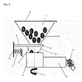
- Fig. 2 the closure element 6 is spent between the discharge opening 3 of the bean container 1 and the filling opening 4 of the grinder 5. It is in its final position.
- the closure element base 13 has also been displaced so that the restoring element 7 arranged between the closure element base 13 and the housing 9 is compressed.
- the rotational movement during operation of the grinder 5 about the axis of rotation 11 activates the slip clutch and generates sufficient force, which holds against the spring force of the return element 7, the closure element 6 via the slip clutch in the end position.
- the resulting from the grinding process in the grinder 5 from the beans 8 coffee powder 12 is discharged through the powder discharge shaft 10 from the grinder 5.
- Fig. 3 a state is shown that occurs after the end of the grinding process.
- the end of the rotational movement about the axis of rotation 11 of the grinder 5 ensures that the non-illustrated slip clutch no longer exerts force on the closure element 6 and against the spring force of the return element 7.
- the restoring element 7 can again assume its original shape and convey the closure element 6 into its initial position by acting on the restoring force on the closure element base 13.
- the filling opening 4 of the grinder 5 and the discharge opening 3 of the bean container 1 are released. So beans 8 can fall into the grinder 5 again for the upcoming grinding process.
- the preceding coffee machine described in detail is an exemplary embodiment, it can be modified in a customary manner by a person skilled in the art to a large extent without departing from the scope of the invention.
- the design and the principle of the closure element can be changed.
- the configuration of the return element and its interaction with the closure element can be made in a different form, if e.g. is necessary for designerischen or space reasons.
- the use of the indefinite article "a” or "an” does not exclude that the characteristics in question may also be present several times or several times.
Landscapes
- Engineering & Computer Science (AREA)
- Mechanical Engineering (AREA)
- Food Science & Technology (AREA)
- Apparatus For Making Beverages (AREA)
Abstract
Description
- Die Erfindung betrifft einen Kaffeevollautomaten mit einem Bohnenbehälter mit einer im Betrieb in Richtung des Mahlwerks zeigenden Abgabeöffnung und mit einem Mahlwerk mit einer in Richtung der Abgabeöffnung des Bohnenbehälters zeigenden Befüllöffnung.
- Kaffeevollautomaten verfügen regelmäßig über einen Bohnenbehälter, in dem ganze Bohnen für die Kaffeebereitung vorgehalten werden. Der Bohnenbehälter hat eine verschließbare Öffnung an seiner Oberseite zum Befüllen mit Bohnen und eine Abgabeöffnung zur Abgabe der Kaffeebohnen, die an der Unterseite des Bohnenbehälters angeordnet ist. Die Öffnung an der Oberseite des Bohnenbehälters ist meist mit einem Deckel verschlossen. So kann das Aroma der Bohnen, insbesondere bei längerer Lagerung im Bohnenbehälter, erhalten werden. Unterhalb der Abgabeöffnung des Bohnenbehälters ist das Mahlwerk angeordnet. Es weist auf seiner Oberseite eine Befüllöffnung auf. Bohnen können aus dem Bohnenbehälter durch die Befüllöffnung in das Mahlwerk hineinfallen. Gemäß der
EP 2 120 658 B1 weist ein abnehmbarer Bohnenbehälter Verschlüsse auf, die den Bohnenbehälter im Bereich der Abgabeöffnung abschließen. Dieser Verschluss lässt sich zur Befüllung des Mahlwerks nach dem Einsetzen des Bohnenbehälters in den Kaffeevollautomaten manuell öffnen. Sobald der Nutzer des Kaffeevollautomaten die Zubereitung eines Kaffees auslöst, beginnt das Mahlwerk mit dem Mahlvorgang, um für den Brühvorgang frisch gemahlenen Kaffee zur Verfügung zu stellen. Dabei werden die aus dem Bohnenbehälter in das Mahlwerk rutschenden Bohnen verarbeitet, wobei die Menge der Bohnen von der Menge des angeforderten Kaffees abhängt. - Beim Betrieb derartiger Kaffeevollautomaten fallen sehr laute Geräusche beim Mahlen auf, die durch das Mahlwerk beim Brechen der Bohnen hervorgerufen werden. Diese Geräusche werden oft durch den trichterförmig gestalteten Bohnenbehälter noch verstärkt. Schalldämpfungselemente, wie z.B. schalldämpfende Deckel der Bohnenbehälter, erfüllen nur zum Teil den Zweck, die Lautstärke des Mahlwerks zu reduzieren. Es liegt jedoch im Interesse des Nutzers, die Geräusche des Mahlwerks deutlicher zu reduzieren, da zu laute Kaffeevollautomaten als störend empfunden werden. Der vorliegenden Erfindung liegt daher die Aufgabe zugrunde, einen Kaffeevollautomaten zur Verfügung zu stellen, bei dem beim Mahlen entstehende Geräusche nicht durch den Bohnenbehälter u. U. sogar dort verstärkt nach außen dringen.
- Diese Aufgabe wird bei dem eingangs genannten Kaffeevollautomaten erfindungsgemäß nach Anspruch 1 dadurch gelöst, dass ein Verschlusselement vorgesehen ist, welches in einer Ruhestellung des Mahlwerks als Ausgangsstellung die Befüllöffnung des Mahlwerks freigibt, und das in einer Betriebsstellung des Mahlwerks als Endstellung die Befüllöffnung abschließt. Entgegen der bisher bekannten Verschlüsse an der Abgabeöffnung des Bohnenbehälters, die während des Mahlvorgangs geöffnet sind, schließt dieser Verschluss das Mahlwerk nach oben zum Bohnenbehälter hin ab. Der Verschluss ist aktiviert, während das Mahlwerk arbeitet, so dass die Geräuschemissionen aus dem Mahlwerk in Richtung des Bohnenbehälters gering gehalten werden können. Verschlüsse nach dem Stand der Technik hingegen wurden nur dazu benötigt, Bohnen im Bohnenbehälter gegen ein Herausfallen nach der Entnahme des Bohnenbehälters aus dem Kaffeevollautomaten zu schützen.
- In einer ersten Ausgestaltungsform der Erfindung kann das Verschlusselement separat, also manuell oder automatenseitig betätigbar sein, wobei verschiedene Ausführungsformen denkbar sind. So kann das Verschlusselement in einer einfachen Ausführung mit der Hand betätigbar sein. Dazu muss der Nutzer vor Beginn eines Kaffeezubereitungsvorgangs durch manuelles Betätigen des Verschlusselements das Mahlwerk an seiner Befüllöffnung verschließen. Alternativ ist ein mechanisch und/oder elektrisch betriebener Verschluss, beispielsweise ein vom Kaffeevollautomaten angesteuerter Magnetschalter denkbar, der im Zusammenhang mit dem Start eines Kaffeezubereitungsvorgangs den Verschluss der Befüllöffnung des Mahlwerks vornimmt.
- In einer dazu alternativen Ausgestaltung des Kaffeevollautomaten kann ein Verschlusselement vorgesehen sein, das durch den Betrieb des Mahlwerks selbst aus der Ausgangsstellung in die Endstellung bewegt wird. Zum Beispiel eine mechanische oder elektromagnetische Koppelung zwischen dem Mahlwerk und dem Verschlusselement kann dafür sorgen, dass es aktiviert, die Befüllöffnung des Mahlwerks also geschlossen ist, sobald das Mahlwerk aktiviert wird. Eine mechanische oder elektromagnetische Anbindung kann zwischen einer Drehachse des Mahlwerks und dem Verschlusselement erfolgen.
- In einer weiteren vorteilhaften Ausgestaltung des Kaffeevollautomaten ist eine Rutschkupplung als Antrieb des Verstellelements vorgesehen. Diese ist zwischen dem Verschlusselement und dem Mahlwerk angeordnet und wirkt derart, dass das Verschlusselement vor die Befüllöffnung bewegt wird, sobald der Mahlprozess beginnt. Beispielsweise kann die Rutschkupplung zwischen einer Förderschnecke, die die Bohnen in das Mahlwerk zwischen die Brechwerkzeuge zwingt, und dem Verschlusselement selbst angeordnet sein. Nach Abschluss des Mahlvorgangs und damit nach dem Ende der Drehbewegung des Mahlwerks ist das Verschlusselement wieder frei und kann in die Ausgangsstellung zurückgestellt werden. Dafür können wiederum manuelle, mechanische oder elektrische Antriebe eingesetzt werden.
- Mit einer Koppelung des Verschlusselements an das Mahlwerk ist dessen Aktivierung während des Betriebs des Mahlwerks sichergestellt. Für ein erneutes Befüllen des Mahlwerks nach einem Mahl- und Brühvorgang kann ein manuelles Betätigen des Verschlusselements zum Öffnen des Bohnenbehälters erforderlich sein. In einer weiteren vorteilhaften Ausgestaltung des Kaffeevollautomaten kann das Verschlusselement ein Rückstellelement aufweisen, durch das das Verschlusselement nach Beendigung des Mahlvorgangs aus der Endstellung in die Ausgangsstellung bewegbar ist. Z.B. ein mechanisches Öffnen des Verschlusses durch den Nutzer oder ein automatisches Öffnen des Verschlusses durch einen elektrischen Vortrieb nach Ende des Mahlvorgangs gewährleistet, dass Bohnen für den folgenden Mahlvorgang verzugslos ins Mahlwerk einfallen können. So wird ein optimaler Betrieb des Kaffeevollautomaten erreicht, bei dem zugleich ein höchstmögliche Schallreduzierung für den Mahlbetrieb erfolgt, in dem das Mahlwerk immer nur dann durch das Verschlusselement verschlossen ist, wenn das Mahlwerk in Betrieb ist.
- In einer weiteren vorteilhaften Ausgestaltung ist das Verschlusselement als Längsschieber ausgestaltet. Dieser ist flächig gehalten und kann quer zur Befüllrichtung aus dem Bohnenbehälter in das Mahlwerk in den Bohnenstrom eingeschoben werden. Der Längsschieber ist ein einfaches und damit kostengünstiges Bauteil, das auch keiner nennenswerten Wartung bedarf. Zudem ist ein solches Element selten reparaturbedürftig und ggf. leicht austauschbar.
- Um den Bohnenstrom noch zuverlässiger zu unterbinden und gleichzeitig die Geräuschemission schnell zu mindern, kann nach einer weiteren vorteilhaften Ausgestaltung des erfindungsgemäßen Kaffeevollautomaten das Verschlusselement als Drehschieber ausgestaltet sein. Beispielsweise kann das Verschlusselement als Fotolinsenverschluss gestaltet sein. Bei einer Ausgestaltung als Drehverschluss wie bei einem Gewürzstreuer lassen sich Bereiche mit Öffnungen innerhalb von gegeneinander verdrehbaren Scheiben zur Deckung bringen, um einen Befüllvorgang zu ermöglichen. Sobald der Mahlvorgang beginnt, werden die Scheiben gegeneinander gedreht und schließen gegenseitig die Bereiche mit den Öffnungen ab. Bei Drehverschlüssen ist im Allgemeinen die Tendenz geringer, Bohnen einzuklemmen. Aus Platzgründen können die beispielhaft genannten Drehschieberarten 3-dimensional bzw. kalottenförmig ausgestaltet sein.
- In einer weiteren vorteilhaften Ausgestaltung des erfindungsgemäßen Kaffeevollautomaten ist das Rückstellelement als Federmechanismus oder schwerkraftgetrieben ausgestaltet. Bei der Ausgestaltung des Rückstellelements als Federmechanismus ist zwischen einem Gehäuse des Kaffeevollautomaten und dem Verschlusselement eine Feder angeordnet, die das Verschlusselement nach Beendigung des Mahlvorgangs aus der Endstellung in die Ausgangsstellung zurück bewegt. Die Feder kann auf verschiedene Arten angeordnet sein. Dabei können Zug- und Druckfedern zum Einsatz kommen, wobei doppelte Evolutfedern als besonders robuste Ausführungsform von Vorteil sein können. Aber auch Schenkel- oder Spiralfedern sind denkbar. Bei Nutzung von Gewichten als Rückstellelement sind diese derart angeordnet, dass das Verschlusselement durch die auf das Gewicht wirkende Schwerkraft in die Ausgangsposition zurückgestellt wird, wobei zum Beispiel aus Platzgründen eine oder mehrere Umlenkungen der Verbindung zwischen dem Verschlusselement und dem Gewicht erforderlich sein können.
- Abnehmbare Bohnenbehälter bieten sich wegen ihrer einfacheren Befüllung an. Sie erfordern eine verschließbare Abgabeöffnung, die jedenfalls zum Befüllen des Mahlwerks geöffnet werden kann. Sie lassen sich auf den erfindungsgemäßen Kaffeevollautomaten aufsetzen. An der Schnittstelle zwischen dem Bohnenbehälter und dem Mahlwerk befinden sich dann zwei Verschlüsse, nämlich der der Abgabeöffnung des Bohnenbehälters einerseits und der erfindungsgemäße der Befüllöffnung des Mahlwerks andererseits. Nach einer besonders vorteilhaften Ausgestaltung des erfindungsgemäßen Kaffeevollautomaten kann das Verschlusselement am abnehmbaren Bohnenbehälter angeordnet sein und ein deaktivierbares Rückstellelement aufweisen. Zur Abnahme des Bohnenbehälters ist das Rückstellelement zu deaktivieren, damit das Verschlusselement die Abgabeöffnung des abgenommenen Bohnenbehälters gegen Herausfallen von Bohnen abschließt. Beim Einsetzen des Bohnenbehälters in oder auf den Kaffeevollautomaten wird das Rückstellelement aktiviert. Das Verschlusselement gibt daraufhin das Mahlwerk frei, weil es durch das Rückstellelement in seine Ausgangsposition überführt wird. Bohnen können in das Mahlwerk hinein fallen. Beim Starten des Mahlvorgangs wird das Verschlusselement wie oben beschrieben erneut bewegt, diesmal in seine Endstellung.
- Um das Verschlusselement sowohl als Verschluss der Abgabeöffnung des Bohnenbehälters als auch als Verschluss der Befüllöffnung des Mahlwerks nutzen zu können, muss das Rückstellelement für den Fall der Entnahme des Bohnenbehälters deaktivierbar sein, das Verschlusselement also ohne Betrieb des Mahlwerks in seine Endstellung verbracht werden. Dazu kann z.B. ein handbetätigter Verschluss des Bohnenbehälters als Deaktivierung in Betracht kommen. Nach einer weiteren vorteilhaften Ausgestaltung der Erfindung kann die Deaktivierung des Rückstellelements bzw. das Verbringen des Verschlusselements in seine Endstellung durch die Abnahmebewegung des Bohnenbehälters vom Kaffeevollautomaten erfolgen. Der abnehmbare Bohnenbehälter kann beispielsweise durch einen Bajonettverschluss am Kaffeevollautomaten gekoppelt sein. Zur (Ent-) Koppelung ist sowohl eine translatorische vertikale Aufsetz- oder Abnahmebewegung als auch eine horizontale rotatorische Bewegung erforderlich. Sie können dazu genutzt werden, eine mechanische (De-) Aktivierung des Rückstellelements und/oder des Verschlusselements auszulösen. Damit kann eine Betätigung durch den Benutzer entfallen und die Zuverlässigkeit der Funktionen des Kaffeevollautomaten gesteigert werden, was einer komfortablen Bedienung des Kaffeevollautomaten dient.
- Das Prinzip der Erfindung wird im Folgenden anhand von Zeichnungen beispielshalber noch näher erläutert. In der Zeichnung zeigen:
-
Figur 1 : das Verschlusselement in der Zusammenwirkung mit Mahlwerk und Bohnenbehälter zu Beginn des Mahlvorgangs, -
Figur 2 : das Verschlusselement in der Zusammenwirkung mit Mahlwerk und Bohnenbehälter während des Mahlvorgangs und -
Figur 3 : das Verschlusselement in der Zusammenwirkung mit Mahlwerk und Bohnenbehälter nach Beendigung des Mahlvorgangs. -
Fig. 1 zeigt die erfindungswesentlichen Elemente des erfindungsgemäßen Kaffeevollautomaten in einer schematischen Darstellung zu Beginn des Mahlvorgangs. Ein Bohnenbehälter 1 ist mit einem Deckel 2 versehen, der eine Öffnung zum Befüllen des Bohnenbehälters 1 mit Kaffeebohnen verschließt und dem Aromaschutz dient. An einer Unterseite des Bohnenbehälters 1 und dem Deckel 2 gegenüber liegt eine Abgabeöffnung 3, durch die Kaffeebohnen in ein Mahlwerk 5 gelangen können. Unterhalb der Abgabeöffnung 3 ist das Mahlwerk 5 angeordnet, das über eine in Richtung der Abgabeöffnung 3 zeigende Befüllöffnung 4 verfügt. Die Befüllöffnung 4 ist derart gestaltet, dass Bohnen 8 aus dem Bohnenbehälter 1 in das Mahlwerk 5 einfallen können. Dies erleichtert ein Trichter 14. Zwischen dem Bohnenbehälter 1 und dem Mahlwerk 5 ist ein Verschlusselement 6 eingefügt, das in Aktion die Befüllöffnung 4 des Mahlwerks 5 in Richtung der Abgabeöffnung 3 verschließt. Das Mahlwerk 5 verfügt über einen Pulverabgabeschacht 10. In derFigur 1 ist das Verschlusselement 6 als waagerecht verschiebbares, flächiges Element bzw. als Längsschieber ausgeführt. Es kann aus der dargestellten Ausgangs- oder Ruhestellung, in der es inaktiv ist, von einer Seite aus in den Bohnenstrom aus dem Bohnenbehälter 1 in das darunter angeordnete Mahlwerk 5 eingefahren werden, um seine Endstellung zu erreichen. An der dem Mahlwerk 5 abgewandten Seite des Verschlusselements 6 ist eine Verschlusselementbasis 13 vorgesehen, an der ein Rückstellelement 7 in Form einer Druckfeder angeordnet ist. Es ist zwischen dem Gehäuse 9 und der Verschlusselementbasis 13 angeordnet und spannt das Verschlusselement 6 in seiner Ausgangsstellung vor. Für den Fall, dass keine Kraft mehr das Verschlusselement 6 in seiner Endstellung hält, stellt sie das Verschlusselement 6 in seine Ausgangsstellung zurück. - Sobald das Mahlwerk 5 in Betrieb genommen wird, wird eine Drehbewegung um die Drehachse 11 erzeugt, welche auf eine nicht näher dargestellte Rutschkupplung übertragen wird. Die Rutschkupplung wirkt zwischen dem Verschlusselement 6 und dem Mahlwerk 5 und dort an einem dem Verschlusselement 6 zugewandten Ende, beispielsweise der Förderschnecke. Sie sorgt dafür, dass das Verschlusselement 6 in der angedeuteten Pfeilrichtung über die Befüllöffnung des Mahlwerks 5 in seine Endstellung verbracht wird. Dabei wird das Rückstellelement 7 gestaucht.
- In
Fig. 2 ist das Verschlusselement 6 zwischen die Abgabeöffnung 3 des Bohnenbehälters 1 und die Befüllöffnung 4 des Mahlwerks 5 verbracht. Es befindet sich in seiner Endstellung. Durch Verschieben des Verschlusselements 6 ist auch die Verschlusselementbasis 13 verschoben worden, so dass das zwischen Verschlusselementbasis 13 und dem Gehäuse 9 angeordnete Rückstellelement 7 gestaucht ist. Die Drehbewegung beim Betrieb des Mahlwerks 5 um die Drehachse 11 aktiviert die Rutschkupplung und erzeugt eine ausreichende Kraft, die entgegen der Federkraft des Rückstellelements 7 das Verschlusselement 6 über die Rutschkupplung in der Endstellung hält. Das durch den Mahlprozess im Mahlwerk 5 aus den Bohnen 8 entstehende Kaffeepulver 12 wird durch den Pulverabgabeschacht 10 aus dem Mahlwerk 5 abgegeben. - In
Fig. 3 wird ein Zustand gezeigt, der nach dem Ende des Mahlvorgangs eintritt. Das Ende der Drehbewegung um die Drehachse 11 des Mahlwerks 5 sorgt dafür, dass die nicht näher dargestellte Rutschkupplung keine Kraft mehr auf das Verschlusselement 6 und entgegen der Federkraft des Rückstellelements 7 ausübt. Dadurch kann das Rückstellelement 7 wieder seine ursprüngliche Form annehmen und durch Wirken der Rückstellkraft auf die Verschlusselementbasis 13 das Verschlusselement 6 in seine Ausgangsstellung befördern. Durch Einnehmen der Ausgangsstellung des Verschlusselements 6 werden die Befüllöffnung 4 des Mahlwerks 5 und die Abgabeöffnung 3 des Bohnenbehälters 1 freigegeben. So können Bohnen 8 erneut für den kommenden Mahlvorgang in das Mahlwerk 5 hinein fallen. - Da es sich bei dem vorhergehenden, detailliert beschriebenen Kaffeevollautomaten um ein Ausführungsbeispiel handelt, kann er in üblicher Weise vom Fachmann in einem weiten Umfang modifiziert werden, ohne den Bereich der Erfindung zu verlassen. Insbesondere können die Gestaltung und das Prinzip des Verschlusselements geändert werden. Ebenso kann die Ausgestaltung des Rückstellelements und dessen Zusammenwirken mit dem Verschlusselement in einer anderen Form vorgenommen werden, wenn dies z.B. aus designerischen oder Platzgründen notwendig ist. Weiter schließt die Verwendung der unbestimmten Artikel "ein" bzw. "eine" nicht aus, dass die betreffenden Merkmale auch mehrfach bzw. mehrmals vorhanden sein können.
-
- 1
- Bohnenbehälter
- 2
- Deckel
- 3
- Abgabeöffnung
- 4
- Befüllöffnung
- 5
- Mahlwerk
- 6
- Verschlusselement
- 7
- Rückstellelement
- 8
- Bohnen
- 9
- Gehäuse
- 10
- Pulverabgabeschacht
- 11
- Drehachse
- 12
- Pulver
- 13
- Verschlusselementbasis
- 14
- Trichter
Claims (10)
- Kaffeevollautomat mit einem Bohnenbehälter (1) mit einer im Betrieb in Richtung eines Mahlwerks (5) zeigenden Abgabeöffnung (3) und mit einem Mahlwerk (5) mit einer in Richtung der Abgabeöffnung (3) des Bohnenbehälters (1) zeigenden Befüllöffnung (4), gekennzeichnet durch ein Verschlusselement (6), das in einer Ruhestellung des Mahlwerks (5) als Ausgangsstellung die Befüllöffnung (4) des Mahlwerks (5) freigibt, und das in einer Betriebsstellung des Mahlwerks (5) als Endstellung die Befüllöffnung (4) abschließt.
- Kaffeevollautomat nach Anspruch 1, dadurch gekennzeichnet, dass das Verschlusselement (6) separat betätigbar ist.
- Kaffeevollautomat nach Anspruch 1, dadurch gekennzeichnet, dass das Verschlusselement (6) durch den Betrieb des Mahlwerks (5) aus der Ausgangsstellung in die Endstellung bewegbar ist.
- Kaffeevollautomat nach dem obigen Anspruch, gekennzeichnet durch eine Rutschkupplung als Antrieb des Verschlusselements (6), die zwischen dem Verschlusselement (6) und dem Mahlwerk (5) angeordnet ist.
- Kaffeevollautomat nach einem der obigen Ansprüche, dadurch gekennzeichnet, dass das Verschlusselement (6) ein Rückstellelement (7) aufweist, durch das das Verschlusselement (6) aus der Endstellung in die Ausgangsstellung bewegbar ist.
- Kaffeevollautomat nach einem der obigen Ansprüche, dadurch gekennzeichnet, dass das Verschlusselement (6) als Längsschieber ausgestaltet ist.
- Kaffeevollautomat nach einem der Ansprüche 1 bis 5, dadurch gekennzeichnet, dass das Verschlusselement (6) als Drehschieber ausgestaltet ist.
- Kaffeevollautomat nach einem der Ansprüche 4 bis 7, gekennzeichnet durch einen Federmechanismus oder ein Gewicht als Rückstellelement (7).
- Kaffeevollautomat nach einem der Ansprüche 4 bis 8, dadurch gekennzeichnet, dass das Verschlusselement (6) an einem abnehmbaren Bohnenbehälter (1) angeordnet ist und ein deaktivierbares Rückstellelement (7) aufweist.
- Kaffeevollautomat nach einem der Ansprüche 4 bis 8, dadurch gekennzeichnet, dass die Deaktivierung des Rückstellelements und/oder das Verbringen des Verschlusselement in seine Endstellung durch die Abnahmebewegung des Bohnenbehälters vom Kaffeevollautomaten erfolgt
Applications Claiming Priority (1)
| Application Number | Priority Date | Filing Date | Title |
|---|---|---|---|
| DE102013216037.2A DE102013216037A1 (de) | 2013-08-13 | 2013-08-13 | Kaffeevollautomat mit Geräuschdämmung |
Publications (2)
| Publication Number | Publication Date |
|---|---|
| EP2837313A1 true EP2837313A1 (de) | 2015-02-18 |
| EP2837313B1 EP2837313B1 (de) | 2016-09-14 |
Family
ID=51225398
Family Applications (1)
| Application Number | Title | Priority Date | Filing Date |
|---|---|---|---|
| EP14178862.0A Active EP2837313B1 (de) | 2013-08-13 | 2014-07-29 | Kaffeevollautomat mit Geräuschdämmung |
Country Status (2)
| Country | Link |
|---|---|
| EP (1) | EP2837313B1 (de) |
| DE (1) | DE102013216037A1 (de) |
Cited By (1)
| Publication number | Priority date | Publication date | Assignee | Title |
|---|---|---|---|---|
| EP3984425A1 (de) * | 2020-10-19 | 2022-04-20 | BSH Hausgeräte GmbH | Kaffeemühle |
Families Citing this family (1)
| Publication number | Priority date | Publication date | Assignee | Title |
|---|---|---|---|---|
| DE102021102743B3 (de) * | 2021-02-05 | 2022-07-07 | Next Level Coffee GmbH | Automatisiert einstellbare Kaffeemaschine und zugehöriger Kaffeebohnenbehälter |
Citations (3)
| Publication number | Priority date | Publication date | Assignee | Title |
|---|---|---|---|---|
| WO2001023095A1 (en) * | 1999-09-17 | 2001-04-05 | Food Equipment Technologies Company, Inc. | Food ingredient grinder assembly and method |
| EP2120658B1 (de) | 2007-02-23 | 2011-08-03 | BSH Bosch und Siemens Hausgeräte GmbH | Abnehmbarer bohnenbehälter mit drehverschluss |
| EP2578123A1 (de) * | 2011-10-04 | 2013-04-10 | Eugster/Frismag AG | Kaffeeautomat und Verfahren zum Einbringen einer Bohnenmenge |
-
2013
- 2013-08-13 DE DE102013216037.2A patent/DE102013216037A1/de not_active Withdrawn
-
2014
- 2014-07-29 EP EP14178862.0A patent/EP2837313B1/de active Active
Patent Citations (3)
| Publication number | Priority date | Publication date | Assignee | Title |
|---|---|---|---|---|
| WO2001023095A1 (en) * | 1999-09-17 | 2001-04-05 | Food Equipment Technologies Company, Inc. | Food ingredient grinder assembly and method |
| EP2120658B1 (de) | 2007-02-23 | 2011-08-03 | BSH Bosch und Siemens Hausgeräte GmbH | Abnehmbarer bohnenbehälter mit drehverschluss |
| EP2578123A1 (de) * | 2011-10-04 | 2013-04-10 | Eugster/Frismag AG | Kaffeeautomat und Verfahren zum Einbringen einer Bohnenmenge |
Cited By (1)
| Publication number | Priority date | Publication date | Assignee | Title |
|---|---|---|---|---|
| EP3984425A1 (de) * | 2020-10-19 | 2022-04-20 | BSH Hausgeräte GmbH | Kaffeemühle |
Also Published As
| Publication number | Publication date |
|---|---|
| EP2837313B1 (de) | 2016-09-14 |
| DE102013216037A1 (de) | 2015-02-19 |
Similar Documents
| Publication | Publication Date | Title |
|---|---|---|
| DE3312991C2 (de) | Vorrichtung zum Zerkleinern von Materialien, wie Dokumenten etc. | |
| EP2030537B1 (de) | Brüheinrichtung für eine Kaffeemaschine | |
| EP1440643B1 (de) | Kaffeebohnenbehälter für einen Kaffeeautomaten | |
| DE202011109919U1 (de) | Kaffeebohnenverpackungspatrone und diese enthaltendes Kaffeegetränksystem | |
| DE102018009992B4 (de) | Füllvorrichtung für wiederbefüllbare Kaffeekapseln und Kaffeemühle mit Füllvorrichtung | |
| DE102013224592A1 (de) | Kaffeevollautomat mit abnehmbarem Bohnenbehälter | |
| DE102008005362A1 (de) | Kaffeevollautomat mit Serviceanzeige | |
| DE102014107647A1 (de) | Kaffeebohnenbehälter | |
| EP2837313B1 (de) | Kaffeevollautomat mit Geräuschdämmung | |
| EP3291714B1 (de) | Kaffeemaschine sowie betriebsverfahren | |
| DE69202666T2 (de) | Automatische Dosiervorrichtung für Mahlgut. | |
| EP2559662B1 (de) | Wasserfilterkanne | |
| DE102016014089B4 (de) | Kaffeemühle mit Füllvorrichtung für wiederbefüllbare Kaffeekapseln | |
| EP3275353B1 (de) | Vorratsbehälteranordnung für ein getränkezubereitungsgerät | |
| DE102006025419A1 (de) | Bewegliches Fenster am Kaffeegerätegehäuse | |
| EP2223640B1 (de) | Kaffeepadmaschine mit Bypass | |
| DE2236782C3 (de) | Geldrückgabeeinrichtung für Münzautomaten, insbesondere für Münzfernsprecher | |
| WO2015157872A1 (de) | Brüheinheit für eine kaffeemaschine sowie kaffeemaschine | |
| EP1885224A1 (de) | Kaffeemaschine | |
| DE202005020774U1 (de) | Kaffeemaschine | |
| DE102012206161B4 (de) | Kaffeevollautomat mit reinigungsfähiger Pulverzuführung | |
| DE102012016560A1 (de) | Espressovollautomat | |
| DE102004035459A1 (de) | Haushaltskaffeemühle | |
| DE29604761U1 (de) | Schriftgutvernichter | |
| DE102022134466A1 (de) | Hybride Getränkezubereitungsvorrichtung mit entnehmbarem Getränkesubstrathalter |
Legal Events
| Date | Code | Title | Description |
|---|---|---|---|
| 17P | Request for examination filed |
Effective date: 20140729 |
|
| AK | Designated contracting states |
Kind code of ref document: A1 Designated state(s): AL AT BE BG CH CY CZ DE DK EE ES FI FR GB GR HR HU IE IS IT LI LT LU LV MC MK MT NL NO PL PT RO RS SE SI SK SM TR |
|
| AX | Request for extension of the european patent |
Extension state: BA ME |
|
| PUAI | Public reference made under article 153(3) epc to a published international application that has entered the european phase |
Free format text: ORIGINAL CODE: 0009012 |
|
| RAP1 | Party data changed (applicant data changed or rights of an application transferred) |
Owner name: BSH HAUSGERAETE GMBH |
|
| R17P | Request for examination filed (corrected) |
Effective date: 20150818 |
|
| RBV | Designated contracting states (corrected) |
Designated state(s): AL AT BE BG CH CY CZ DE DK EE ES FI FR GB GR HR HU IE IS IT LI LT LU LV MC MK MT NL NO PL PT RO RS SE SI SK SM TR |
|
| GRAP | Despatch of communication of intention to grant a patent |
Free format text: ORIGINAL CODE: EPIDOSNIGR1 |
|
| INTG | Intention to grant announced |
Effective date: 20160323 |
|
| GRAS | Grant fee paid |
Free format text: ORIGINAL CODE: EPIDOSNIGR3 |
|
| GRAA | (expected) grant |
Free format text: ORIGINAL CODE: 0009210 |
|
| AK | Designated contracting states |
Kind code of ref document: B1 Designated state(s): AL AT BE BG CH CY CZ DE DK EE ES FI FR GB GR HR HU IE IS IT LI LT LU LV MC MK MT NL NO PL PT RO RS SE SI SK SM TR |
|
| REG | Reference to a national code |
Ref country code: GB Ref legal event code: FG4D Free format text: NOT ENGLISH |
|
| REG | Reference to a national code |
Ref country code: CH Ref legal event code: EP |
|
| REG | Reference to a national code |
Ref country code: IE Ref legal event code: FG4D Free format text: LANGUAGE OF EP DOCUMENT: GERMAN |
|
| REG | Reference to a national code |
Ref country code: AT Ref legal event code: REF Ref document number: 827966 Country of ref document: AT Kind code of ref document: T Effective date: 20161015 |
|
| REG | Reference to a national code |
Ref country code: DE Ref legal event code: R096 Ref document number: 502014001443 Country of ref document: DE |
|
| REG | Reference to a national code |
Ref country code: LT Ref legal event code: MG4D |
|
| REG | Reference to a national code |
Ref country code: NL Ref legal event code: MP Effective date: 20160914 |
|
| PG25 | Lapsed in a contracting state [announced via postgrant information from national office to epo] |
Ref country code: RS Free format text: LAPSE BECAUSE OF FAILURE TO SUBMIT A TRANSLATION OF THE DESCRIPTION OR TO PAY THE FEE WITHIN THE PRESCRIBED TIME-LIMIT Effective date: 20160914 Ref country code: LT Free format text: LAPSE BECAUSE OF FAILURE TO SUBMIT A TRANSLATION OF THE DESCRIPTION OR TO PAY THE FEE WITHIN THE PRESCRIBED TIME-LIMIT Effective date: 20160914 Ref country code: FI Free format text: LAPSE BECAUSE OF FAILURE TO SUBMIT A TRANSLATION OF THE DESCRIPTION OR TO PAY THE FEE WITHIN THE PRESCRIBED TIME-LIMIT Effective date: 20160914 Ref country code: HR Free format text: LAPSE BECAUSE OF FAILURE TO SUBMIT A TRANSLATION OF THE DESCRIPTION OR TO PAY THE FEE WITHIN THE PRESCRIBED TIME-LIMIT Effective date: 20160914 Ref country code: NO Free format text: LAPSE BECAUSE OF FAILURE TO SUBMIT A TRANSLATION OF THE DESCRIPTION OR TO PAY THE FEE WITHIN THE PRESCRIBED TIME-LIMIT Effective date: 20161214 |
|
| PG25 | Lapsed in a contracting state [announced via postgrant information from national office to epo] |
Ref country code: SE Free format text: LAPSE BECAUSE OF FAILURE TO SUBMIT A TRANSLATION OF THE DESCRIPTION OR TO PAY THE FEE WITHIN THE PRESCRIBED TIME-LIMIT Effective date: 20160914 Ref country code: GR Free format text: LAPSE BECAUSE OF FAILURE TO SUBMIT A TRANSLATION OF THE DESCRIPTION OR TO PAY THE FEE WITHIN THE PRESCRIBED TIME-LIMIT Effective date: 20161215 Ref country code: NL Free format text: LAPSE BECAUSE OF FAILURE TO SUBMIT A TRANSLATION OF THE DESCRIPTION OR TO PAY THE FEE WITHIN THE PRESCRIBED TIME-LIMIT Effective date: 20160914 Ref country code: LV Free format text: LAPSE BECAUSE OF FAILURE TO SUBMIT A TRANSLATION OF THE DESCRIPTION OR TO PAY THE FEE WITHIN THE PRESCRIBED TIME-LIMIT Effective date: 20160914 |
|
| PG25 | Lapsed in a contracting state [announced via postgrant information from national office to epo] |
Ref country code: EE Free format text: LAPSE BECAUSE OF FAILURE TO SUBMIT A TRANSLATION OF THE DESCRIPTION OR TO PAY THE FEE WITHIN THE PRESCRIBED TIME-LIMIT Effective date: 20160914 Ref country code: RO Free format text: LAPSE BECAUSE OF FAILURE TO SUBMIT A TRANSLATION OF THE DESCRIPTION OR TO PAY THE FEE WITHIN THE PRESCRIBED TIME-LIMIT Effective date: 20160914 |
|
| PG25 | Lapsed in a contracting state [announced via postgrant information from national office to epo] |
Ref country code: PL Free format text: LAPSE BECAUSE OF FAILURE TO SUBMIT A TRANSLATION OF THE DESCRIPTION OR TO PAY THE FEE WITHIN THE PRESCRIBED TIME-LIMIT Effective date: 20160914 Ref country code: SM Free format text: LAPSE BECAUSE OF FAILURE TO SUBMIT A TRANSLATION OF THE DESCRIPTION OR TO PAY THE FEE WITHIN THE PRESCRIBED TIME-LIMIT Effective date: 20160914 Ref country code: CZ Free format text: LAPSE BECAUSE OF FAILURE TO SUBMIT A TRANSLATION OF THE DESCRIPTION OR TO PAY THE FEE WITHIN THE PRESCRIBED TIME-LIMIT Effective date: 20160914 Ref country code: IS Free format text: LAPSE BECAUSE OF FAILURE TO SUBMIT A TRANSLATION OF THE DESCRIPTION OR TO PAY THE FEE WITHIN THE PRESCRIBED TIME-LIMIT Effective date: 20170114 Ref country code: ES Free format text: LAPSE BECAUSE OF FAILURE TO SUBMIT A TRANSLATION OF THE DESCRIPTION OR TO PAY THE FEE WITHIN THE PRESCRIBED TIME-LIMIT Effective date: 20160914 Ref country code: PT Free format text: LAPSE BECAUSE OF FAILURE TO SUBMIT A TRANSLATION OF THE DESCRIPTION OR TO PAY THE FEE WITHIN THE PRESCRIBED TIME-LIMIT Effective date: 20170116 Ref country code: BG Free format text: LAPSE BECAUSE OF FAILURE TO SUBMIT A TRANSLATION OF THE DESCRIPTION OR TO PAY THE FEE WITHIN THE PRESCRIBED TIME-LIMIT Effective date: 20161214 Ref country code: SK Free format text: LAPSE BECAUSE OF FAILURE TO SUBMIT A TRANSLATION OF THE DESCRIPTION OR TO PAY THE FEE WITHIN THE PRESCRIBED TIME-LIMIT Effective date: 20160914 |
|
| REG | Reference to a national code |
Ref country code: DE Ref legal event code: R097 Ref document number: 502014001443 Country of ref document: DE |
|
| REG | Reference to a national code |
Ref country code: FR Ref legal event code: PLFP Year of fee payment: 4 |
|
| PLBE | No opposition filed within time limit |
Free format text: ORIGINAL CODE: 0009261 |
|
| STAA | Information on the status of an ep patent application or granted ep patent |
Free format text: STATUS: NO OPPOSITION FILED WITHIN TIME LIMIT |
|
| PG25 | Lapsed in a contracting state [announced via postgrant information from national office to epo] |
Ref country code: DK Free format text: LAPSE BECAUSE OF FAILURE TO SUBMIT A TRANSLATION OF THE DESCRIPTION OR TO PAY THE FEE WITHIN THE PRESCRIBED TIME-LIMIT Effective date: 20160914 |
|
| 26N | No opposition filed |
Effective date: 20170615 |
|
| PG25 | Lapsed in a contracting state [announced via postgrant information from national office to epo] |
Ref country code: SI Free format text: LAPSE BECAUSE OF FAILURE TO SUBMIT A TRANSLATION OF THE DESCRIPTION OR TO PAY THE FEE WITHIN THE PRESCRIBED TIME-LIMIT Effective date: 20160914 |
|
| REG | Reference to a national code |
Ref country code: IE Ref legal event code: MM4A |
|
| REG | Reference to a national code |
Ref country code: BE Ref legal event code: MM Effective date: 20170731 |
|
| PG25 | Lapsed in a contracting state [announced via postgrant information from national office to epo] |
Ref country code: LU Free format text: LAPSE BECAUSE OF NON-PAYMENT OF DUE FEES Effective date: 20170729 |
|
| REG | Reference to a national code |
Ref country code: FR Ref legal event code: PLFP Year of fee payment: 5 |
|
| PG25 | Lapsed in a contracting state [announced via postgrant information from national office to epo] |
Ref country code: IE Free format text: LAPSE BECAUSE OF NON-PAYMENT OF DUE FEES Effective date: 20170729 |
|
| PG25 | Lapsed in a contracting state [announced via postgrant information from national office to epo] |
Ref country code: BE Free format text: LAPSE BECAUSE OF NON-PAYMENT OF DUE FEES Effective date: 20170731 |
|
| PG25 | Lapsed in a contracting state [announced via postgrant information from national office to epo] |
Ref country code: MT Free format text: LAPSE BECAUSE OF FAILURE TO SUBMIT A TRANSLATION OF THE DESCRIPTION OR TO PAY THE FEE WITHIN THE PRESCRIBED TIME-LIMIT Effective date: 20160914 |
|
| PG25 | Lapsed in a contracting state [announced via postgrant information from national office to epo] |
Ref country code: AL Free format text: LAPSE BECAUSE OF FAILURE TO SUBMIT A TRANSLATION OF THE DESCRIPTION OR TO PAY THE FEE WITHIN THE PRESCRIBED TIME-LIMIT Effective date: 20160914 |
|
| PG25 | Lapsed in a contracting state [announced via postgrant information from national office to epo] |
Ref country code: HU Free format text: LAPSE BECAUSE OF FAILURE TO SUBMIT A TRANSLATION OF THE DESCRIPTION OR TO PAY THE FEE WITHIN THE PRESCRIBED TIME-LIMIT; INVALID AB INITIO Effective date: 20140729 Ref country code: MC Free format text: LAPSE BECAUSE OF FAILURE TO SUBMIT A TRANSLATION OF THE DESCRIPTION OR TO PAY THE FEE WITHIN THE PRESCRIBED TIME-LIMIT Effective date: 20160914 |
|
| PG25 | Lapsed in a contracting state [announced via postgrant information from national office to epo] |
Ref country code: CY Free format text: LAPSE BECAUSE OF FAILURE TO SUBMIT A TRANSLATION OF THE DESCRIPTION OR TO PAY THE FEE WITHIN THE PRESCRIBED TIME-LIMIT Effective date: 20160914 |
|
| PG25 | Lapsed in a contracting state [announced via postgrant information from national office to epo] |
Ref country code: MK Free format text: LAPSE BECAUSE OF FAILURE TO SUBMIT A TRANSLATION OF THE DESCRIPTION OR TO PAY THE FEE WITHIN THE PRESCRIBED TIME-LIMIT Effective date: 20160914 |
|
| PG25 | Lapsed in a contracting state [announced via postgrant information from national office to epo] |
Ref country code: TR Free format text: LAPSE BECAUSE OF FAILURE TO SUBMIT A TRANSLATION OF THE DESCRIPTION OR TO PAY THE FEE WITHIN THE PRESCRIBED TIME-LIMIT Effective date: 20160914 |
|
| REG | Reference to a national code |
Ref country code: AT Ref legal event code: MM01 Ref document number: 827966 Country of ref document: AT Kind code of ref document: T Effective date: 20190729 |
|
| PG25 | Lapsed in a contracting state [announced via postgrant information from national office to epo] |
Ref country code: AT Free format text: LAPSE BECAUSE OF NON-PAYMENT OF DUE FEES Effective date: 20190729 |
|
| PGFP | Annual fee paid to national office [announced via postgrant information from national office to epo] |
Ref country code: DE Payment date: 20250731 Year of fee payment: 12 |
|
| PGFP | Annual fee paid to national office [announced via postgrant information from national office to epo] |
Ref country code: IT Payment date: 20250731 Year of fee payment: 12 |
|
| PGFP | Annual fee paid to national office [announced via postgrant information from national office to epo] |
Ref country code: GB Payment date: 20250724 Year of fee payment: 12 |
|
| PGFP | Annual fee paid to national office [announced via postgrant information from national office to epo] |
Ref country code: FR Payment date: 20250723 Year of fee payment: 12 |
|
| PGFP | Annual fee paid to national office [announced via postgrant information from national office to epo] |
Ref country code: CH Payment date: 20250801 Year of fee payment: 12 |