EP2837149B1 - Methods and systems for virtualization of storage services in an integrated chassis - Google Patents
Methods and systems for virtualization of storage services in an integrated chassis Download PDFInfo
- Publication number
- EP2837149B1 EP2837149B1 EP13717921.4A EP13717921A EP2837149B1 EP 2837149 B1 EP2837149 B1 EP 2837149B1 EP 13717921 A EP13717921 A EP 13717921A EP 2837149 B1 EP2837149 B1 EP 2837149B1
- Authority
- EP
- European Patent Office
- Prior art keywords
- chassis
- storage
- management
- datagram
- controller
- Prior art date
- Legal status (The legal status is an assumption and is not a legal conclusion. Google has not performed a legal analysis and makes no representation as to the accuracy of the status listed.)
- Active
Links
- 238000000034 method Methods 0.000 title claims description 30
- 230000002093 peripheral effect Effects 0.000 claims description 6
- 230000005540 biological transmission Effects 0.000 claims description 5
- 238000007726 management method Methods 0.000 description 109
- 238000004891 communication Methods 0.000 description 24
- 230000003287 optical effect Effects 0.000 description 12
- 230000015654 memory Effects 0.000 description 9
- 230000008569 process Effects 0.000 description 7
- 230000008901 benefit Effects 0.000 description 6
- 238000003491 array Methods 0.000 description 3
- 238000012545 processing Methods 0.000 description 3
- 230000002776 aggregation Effects 0.000 description 2
- 238000004220 aggregation Methods 0.000 description 2
- 238000004458 analytical method Methods 0.000 description 2
- 238000013500 data storage Methods 0.000 description 2
- 238000010586 diagram Methods 0.000 description 2
- 238000005516 engineering process Methods 0.000 description 2
- 230000006870 function Effects 0.000 description 2
- 230000007246 mechanism Effects 0.000 description 2
- 230000006855 networking Effects 0.000 description 2
- 230000003863 physical function Effects 0.000 description 2
- 239000000969 carrier Substances 0.000 description 1
- 238000013461 design Methods 0.000 description 1
- 238000001514 detection method Methods 0.000 description 1
- 230000000694 effects Effects 0.000 description 1
- 229940082150 encore Drugs 0.000 description 1
- 239000004973 liquid crystal related substance Substances 0.000 description 1
- 238000013507 mapping Methods 0.000 description 1
- 239000013307 optical fiber Substances 0.000 description 1
- 238000012634 optical imaging Methods 0.000 description 1
- 238000011084 recovery Methods 0.000 description 1
- 239000007787 solid Substances 0.000 description 1
- 238000010897 surface acoustic wave method Methods 0.000 description 1
Images
Classifications
-
- G—PHYSICS
- G06—COMPUTING; CALCULATING OR COUNTING
- G06F—ELECTRIC DIGITAL DATA PROCESSING
- G06F13/00—Interconnection of, or transfer of information or other signals between, memories, input/output devices or central processing units
- G06F13/38—Information transfer, e.g. on bus
- G06F13/40—Bus structure
- G06F13/4004—Coupling between buses
- G06F13/4022—Coupling between buses using switching circuits, e.g. switching matrix, connection or expansion network
-
- H—ELECTRICITY
- H04—ELECTRIC COMMUNICATION TECHNIQUE
- H04L—TRANSMISSION OF DIGITAL INFORMATION, e.g. TELEGRAPHIC COMMUNICATION
- H04L49/00—Packet switching elements
- H04L49/15—Interconnection of switching modules
Definitions
- the present disclosure relates in general to information handling systems, and more particularly to virtualization of storage services in an integrated chassis.
- An information handling system generally processes, compiles, stores, and/or communicates information or data for business, personal, or other purposes thereby allowing users to take advantage of the value of the information.
- information handling systems may also vary regarding what information is handled, how the information is handled, how much information is processed, stored, or communicated, and how quickly and efficiently the information may be processed, stored, or communicated.
- the variations in information handling systems allow for information handling systems to be general or configured for a specific user or specific use such as financial transaction processing, airline reservations, enterprise data storage, or global communications.
- information handling systems may include a variety of hardware and software components that may be configured to process, store, and communicate information and may include one or more computer systems, data storage systems, and networking systems.
- a system chassis with multiple information handling systems with various peripheral and input/output capabilities common to the chassis as a whole may provide advantages, as it allows a blade server chassis in a small form factor, thereby providing a blade server chassis with a size comparable to the size of a monolithic server.
- Implementation of a system chassis with multiple information handling systems with various peripheral and input/output capabilities common to the chassis as a whole presents numerous challenges.
- US 2012/063304 A1 concerns manageability tools which are provided for allowing an administrator to have better control over switches in a lossless network of switches. These tools provide the ability to detect slow drain and congestion bottlenecks, detect stuck virtual channels and loss of credits, while hold times on edge ASICs to be different from hold times offer ASICs, and mitigate severe latency bottlenecks.
- a system may include a chassis, one or more chassis management controllers housed in the chassis, and a switch management controller.
- the chassis may be configured to receive a plurality of modular information handling systems.
- the one or more chassis management controllers may be configured to receive a storage management command, encapsulate the storage management command in a first datagram, and communicate the first datagram to a switch management controller housed in the chassis.
- the switch management controller may be configured to extract the storage management command from the first datagram, identify a storage controller associated with the storage management command, and communicate an input/output control request to the storage controller based on the storage management command.
- a method may include receiving a storage management command at a chassis management controller housed in a chassis configured to receive a plurality of modular information handling systems, encapsulating the storage management command in a first datagram, communicating the first datagram from the chassis management controller to a switch management controller housed in the chassis, extracting the storage management command from the first datagram, identifying a storage controller associated with the storage management command, and communicating an input/output control request from the switch management controller to the storage controller based on the storage management command.
- FIGURES 1 and 2 wherein like numbers are used to indicate like and corresponding parts.
- an information handling system may include any instrumentality or aggregate of instrumentalities operable to compute, classify, process, transmit, receive, retrieve, originate, switch, store, display, manifest, detect, record, reproduce, handle, or utilize any form of information, intelligence, or data for business, scientific, control, entertainment, or other purposes.
- an information handling system may be a personal computer, a PDA, a consumer electronic device, a network storage device, or any other suitable device and may vary in size, shape, performance, functionality, and price.
- the information handling system may include memory, one or more processing resources such as a central processing unit (CPU) or hardware or software control logic.
- Additional components or the information handling system may include one or more storage devices, one or more communications ports for communicating with external devices as well as various input and output (I/O) devices, such as a keyboard, a mouse, and a video display.
- the information handling system may also include one or more buses operable to transmit communication between the various hardware components.
- information handling resources may broadly refer to any component system, device or apparatus of an information handling system, including without limitation processors, busses, memories, input-output devices and/or interfaces, storage resources, network interfaces, motherboards, electromechanical devices (e.g., fans), displays, and power supplies.
- Computer-readable media may include any instrumentality or aggregation of instrumentalities that may retain data and/or instructions for a period of time.
- Computer-readable media may include, without limitation, storage media such as a direct access storage device (e.g., a hard disk drive or floppy disk), a sequential access storage device (e.g., a tape disk drive), compact disk, CD-ROM, DVD, random access memory (RAM), read-only memory (ROM), electrically erasable programmable read-only memory (EEPROM), and/or flash memory; as well as communications media such wires, optical fibers, microwaves, radio waves, and other electromagnetic and/or optical carriers; and/or any combination of the foregoing.
- direct access storage device e.g., a hard disk drive or floppy disk
- sequential access storage device e.g., a tape disk drive
- compact disk CD-ROM, DVD, random access memory (RAM)
- RAM random access memory
- ROM read-only memory
- EEPROM electrically erasable
- Information handling systems often use an array of physical storage resources (e.g., disk drives), such as a Redundant Array of Independent Disks (RAID), for example, for storing information.
- Arrays of physical storage resources typically utilize multiple disks to perform input and output operations and can be structured to provide redundancy which may increase fault tolerance. Other advantages of arrays of physical storage resources may be increased data integrity, throughput and/or capacity.
- one or more physical storage resources disposed in an array of physical storage resources may appear to an operating system as a single logical storage unit or "logical unit.” Implementations of physical storage resource arrays can range from a few physical storage resources disposed in a chassis, to hundreds of physical storage resources disposed in one or more separate storage enclosures.
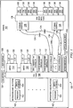
- FIGURE 1 illustrates a block diagram of an example system 100 having a chassis 101 with multiple information handling systems 102 and with various peripheral and input/output capabilities common to chassis 101 as a whole, in accordance with certain embodiments of the present disclosure.
- system 100 may comprise a chassis 101 including a plurality of information handling systems 102, a mid-plane 106, one or more switches 110, a switch management controller 111, one or more chassis management controller 112, a network interface 116, one or more slots 120, one or more cables 124, one or more storage interfaces 126, a disk drive backplane 128, a plurality of disk drives 130, an optical media drive 132, a keyboard-video-mouse (KVM) interface 134, and a user interface 136.
- KVM keyboard-video-mouse
- An information handling system 102 may generally be operable to receive data from and/or communicate data to one or more disk drives 130 and/or other information handling resources of chassis 101 via mid-plane 106.
- an information handling system 102 may be a server.
- an information handling system may comprise a blade server having modular physical design.
- an information handling system 102 may comprise an M class server.
- an information handling system 102 may include a processor 103 and one or more switch interfaces 104 communicatively coupled to the processor 103.
- a processor 103 may include any system, device, or apparatus configured to interpret and/or execute program instructions and/or process data, and may include, without limitation a microprocessor, microcontroller, digital signal processor (DSP), application specific integrated circuit (ASIC), or any other digital or analog circuitry configured to interpret and/or execute program instructions and/or process data.
- processor 103 may interpret and/or execute program instructions and/or process data stored in a memory, a hard drive 130, and/or another component of system 100.
- a switch interface 104 may comprise any system, device, or apparatus configured to provide an interface between its associated information handling system 102 and switches 110.
- switches 110 may comprise Peripheral Component Interconnect Express (PCIe) switches, in which case a switch interface 104 may comprise a mezzanine card configured to create a PCIe-compliant interface between its associated information handling system 102 and switches 110.
- PCIe Peripheral Component Interconnect Express
- a switch interface 104 may comprise an interposer.
- Use of switch interfaces 104 in information handling systems 102 may allow for minimal changes to be made to traditional servers (e.g., M class servers) while supporting the overall system architecture disclosed herein.
- FIGURE 1 depicts an implementation including a single switch interface 104 per information handling system 102, in some embodiments each information handling system 102 may include a plurality of switch interfaces 102 for redundancy, high availability, and/or other reasons.
- Mid-plane 106 may comprise any system, device, or apparatus configured to interconnect modular information handling systems 102 with information handling resources of chassis 101. Accordingly, mid-plane 106 may include slots and/or connectors configured to receive information handling systems 102, switches 110, switch management controller 111, chassis management controllers 112, storage controllers 114, network interface 116, optical media drive 132, KVM interface 134, user interface 136, and/or other information handling resources. In one embodiment, mid-plane 106 may include a single board configured to interconnect modular information handling systems 102 with information handling resources. In another embodiment, mid-plane 106 may include multiple boards configured to interconnect modular information handling systems 102 with information handling resources. In yet another embodiment, mid-plane 106 may include cabling configured to interconnect modular information handling systems 102 with information handling resources.
- a switch 110 may comprise any system, device, or apparatus configured to couple information handling systems 102 to storage controllers 114 (e.g., via mid-plane 106) and slots 120 and perform switching between information handling systems 102 and various information handling resources of system 100, including storage controllers 114 and slots 120.
- a switch 110 may comprise a PCIe switch.
- a switch may comprise a generalized PC bus switch, an Infiniband switch, or other suitable switch.
- chassis 101 may include a plurality of switches 110.
- switches 110 may operate in a redundant mode for shared devices (e.g., storage controllers 114 and/or devices coupled to slots 120) and in non-redundant mode for non-shared/zoned devices.
- shared devices may refer to those which may be visible to more than one information handling system 102, while non-shared devices may refer to those which are visible to only a single information handling system 102.
- a chassis management controller 112 may be any system, device, or apparatus configured to facilitate management and/or control of system 100, its information handling systems 102, and/or one or more of its component its component information handling resources.
- a chassis management controller 102 may be configured to issue commands and/or other signals to manage and/or control information handling system 102 and/or information handling resources of system 100.
- a chassis management controller 112 may comprise a microprocessor, microcontroller, digital signal processor (DSP), application specific integrated circuit (ASIC), field programmable gate array (FPGA), erasable programmable read-only memory (EPROM), or any combination thereof. As shown in FIGURE 1 , a chassis management controller 112 may be coupled to mid-plane 106.
- system 100 may include a plurality of chassis management controllers 112, and in such embodiments, chassis management controllers 112 may be configured as redundant.
- a chassis management controller 112 may provide a user interface and high level controls for management of switches 110, including configuring assignments of individual information handling systems 102 to non-shared information handling resources of system 100.
- a chassis management controller may define configurations of the storage subsystem (e.g., storage controllers 114, storage interfaces 126, disk drives 130, etc.) of system 100.
- a chassis management controller may provide physical function configuration and status information that would normally occur at the driver level in traditional server implementations. Examples of physical functions include disk drive discovery and status, RAID configuration and logical volume mapping.
- a chassis management controller 112 may also provide a management console for user/administrator access to these functions.
- a chassis management controller 112 may implement Intelligent Platform Management Interface (IPMI) or another suitable management protocol permitting a user to remotely access a chassis management controller 112 to configure system 100 and its various information handling resources.
- IPMI Intelligent Platform Management Interface
- a chassis management controller 112 may interface with a network interface separate from network interface 116, thus allowing for "out-of-band" control of 100, such that communications to and from chassis management controller 112 are communicated via a management channel physically isolated from an "in band" communication channel with network interface 116.
- chassis management controller 112 may allow an administrator to remotely manage one or parameters associated with operation of system 100 and its various information handling resources (e.g., power usage, processor allocation, memory allocation, security privileges, etc.).
- FIGURE 1 depicts chassis as having two chassis management controllers 112, chassis 101 may include any suitable number chassis management controllers 112.
- a storage controller 114 may and include any system, apparatus, or device operable to manage the communication of data between one or more of information handling systems 102 and one or more of disk drives 130.
- a storage controller 114 may provide functionality including, without limitation, disk aggregation and redundancy (e.g., RAID), input/output (I/O) routing, and error detection and recovery.
- a storage controller 114 may coupled to a connector on mid-plane 106.
- system 100 may include a plurality of storage controllers 114, and in such embodiments, storage controllers 114 may be configured as redundant.
- storage controllers 114 may in some embodiments be shared among two or more information handling systems 102. As also shown in FIGURE 1 , each storage controller 114 may be coupled to one or more storage interfaces 126 via cables 124. For example, in some embodiments, each storage controller 114 may be coupled to a single associated storage interface 126 via a cable 124. In other embodiments, each storage controller 114 may be coupled to two or more storage interfaces 126 via a plurality of cables 124, thus permitting redundancy as shown in FIGURE 1 . Storage controllers 114 may also have features supporting shared storage and high availability. For example, in PCIe implementations, a unique PCIe identifier may be used to indicate shared storage capability and compatibility in system 100.
- chassis management controllers 112 may not be able to communicate directly with switches 110.
- Available chassis management controllers 112 may not be configured in accordance with PCIe or other communication standards available in switches 110, and it may not be desirable to create a proprietary chassis management controller 112 configured in accordance with PCIe or such other communication standards for use in system 100 due to cost concerns. Accordingly, challenges may exist in enabling management functionality of storage devices (e.g., disk drives 130) via chassis management controllers 112 as direct PCIe communications (or communications via another communication protocol) may not be available between
- a switch management controller 111 may be communicatively interfaced between chassis management controllers 112 and switches 110, and configured to virtualize management communications between chassis management controllers 112 and switches 110 related to management of storage components (e.g., storage controllers 114, disk drives 130) and/or other components of system 100.
- Switch management controller 111 may, in some embodiments, interface with switches 110 via a private network (e.g., an Ethernet network) internal to chassis 101.
- each switch 110 and switch management controller 111 may establish a Transmission Control Protocol/Internet Protocol (TCP/IP) socket for communication.
- TCP/IP Transmission Control Protocol/Internet Protocol
- switch management controller 111 may comprise a power PC management processor or processor similar in structure and/or function.
- a chassis management controller 112 may receive a storage management command (e.g., a storage application programming interface (API) call) from a management console or other interface. Chassis management controller 112 may encapsulate such command in a network datagram (e.g., an Ethernet packet, frame, or other datagram) and communicate such datagram via the private network to switch management controller 111. Switch management controller 111 may receive such datagram and extract the command from the datagram. Based on analysis of the command, storage management controller 111 may identify a storage controller 114 associated with the command and execute an input/output control request to such storage controller 114 via an appropriate switch 110.
- a storage management command e.g., a storage application programming interface (API) call
- Chassis management controller 112 may encapsulate such command in a network datagram (e.g., an Ethernet packet, frame, or other datagram) and communicate such datagram via the private network to switch management controller 111.
- Switch management controller 111 may receive such datagram and extract the command from
- the storage controller 114 may communicate a reply (e.g., a return code) via an appropriate switch to storage management controller 111, which reply storage management controller 111 may encapsulate into a network datagram (e.g., an Ethernet packet, frame, or other datagram) and communicate such datagram via the private network to a chassis management controller 112.
- the chassis management controller 112 may extract the reply from the datagram and interpret such reply and/or forward the reply to a management console interfaced to the chassis management controller.
- a switch 110 may have coupled thereto one or more slots 120.
- a slot 120 may include any system, device, or apparatus configured to allow addition of one or more expansion cards to chassis 101 in order to electrically coupled such expansion cards to a switch 110.
- Such slots 120 may comprise any suitable combination of full-height risers, full-height slots, and low-profile slots.
- a full-height riser may include any system, device, or apparatus configured to allow addition of one or more expansion cards (e.g., a full-height slot) having a physical profile or form factor with dimensions that practically prevent such expansion cards to be coupled in a particular manner (e.g., perpendicularly) to mid-plane 106 and/or switch 110 (e.g., the proximity of information handling resources in chassis 101 prevents physical placement of an expansion card in such manner).
- a full-height riser may itself physically couple with a low-profile to mid-plane 106, a switch 110, or another components, and full-height cards may then be coupled to full-height slots of full-height riser.
- low-profile slots may be configured to couple low-profile expansion cards to switches 110 without the need for a full-height riser.
- Slots 120 may also include electrically conductive elements (e.g., edge connectors, traces, etc.) allowing for expansion cards inserted into slots 120 to be electrically coupled to switches 110.
- switches 110 may manage switching of communications between individual information handling systems 102 and expansion cards coupled to slots 120.
- slots 120 may be nonshared (e.g., each slot 120 is associated with a single information handling system 102).
- one or more of slots 120 may be shared among two or more information handling systems 102.
- one or more slots 120 may be configured to be compatible with PCIe, generalized PC bus switch, Infiniband, or other suitable communication specification, standard, or protocol.
- Network interface 116 may include any suitable system, apparatus, or device operable to serve as an interface between chassis 101 and an external network (e.g., a local area network or other network).
- Network interface 116 may enable information handling systems 102 to communicate with the external network using any suitable transmission protocol (e.g., TCP/IP) and/or standard (e.g., IEEE 802.11, Wi-Fi).
- network interface 116 may include a network interface card (NIC).
- NIC network interface card
- network interface 116 may be configured to communicate via wireless transmissions.
- network interface 116 may provide physical access to a networking medium and/or provide a low-level addressing system (e.g., through the use of Media Access Control addresses).
- network interface 116 may be implemented as a local area network (LAN) on motherboard (LOM) interface.
- LAN local area network
- LOM low-level addressing system
- chassis 101 may be coupled to a planar.
- a planar may interconnect switches 110, chassis management controller 112, storage controllers 114, network interface 116, optical media drive 132, KVM interface 134, user interface 136, and/or other modular information handling resources of chassis 101 to mid-plane 106 of system 100.
- such planar may include slots and/or connectors configured to interconnect with such information handling resources.
- Storage interfaces 126 may include any system, device, or apparatus configured to facilitate communication between storage controllers 114 and disk drives 130.
- a storage interface may serve to permit a relatively small number of communication links (e.g., two) between storage controllers 114 and storage interfaces 126 to communicate with a greater number of disk drives 130.
- a storage interface 126 may provide a switching mechanism and/or disk drive addressing mechanism that allows an information handling system 102 to communicate with numerous disk drives 130 via a limited number of communication links and/or channels.
- a storage interface 126 may operate like an Ethernet hub or network switch that allows multiple systems to be coupled using a single switch port (or relatively few switch ports).
- a storage interface 126 may be implemented as an expander (e.g., a Serial Attached SCSI (SAS) expander), an Ethernet switch, a FibreChannel switch, Internet Small Computer System Interface (iSCSI) switch, or any other suitable switch.
- SAS Serial Attached SCSI
- iSCSI Internet Small Computer System Interface
- system 100 may implement a plurality of redundant storage interfaces 126, as shown in FIGURE 1 .
- Disk drive backplane 128 may comprise any system, device, or apparatus configured to interconnect modular storage interfaces 126 with modular disk drives 130. Accordingly, disk drive backplane 128 may include slots and/or connectors configured to receive storage interfaces 126 and/or disk drives 130. In some embodiments, system 100 may include two or more backplanes, in order to support differently-sized disk drive form factors. To support redundancy and high availability, a backplane 128 may be configured to receive a plurality (e.g., 2) of storage interfaces 126 which couple two storage controllers 114 to each disk drive 130.
- a plurality e.g., 2
- Each disk drive 130 may include computer-readable media (e.g., magnetic storage media, optical storage media, opto-magnetic storage media, and/or other type of rotating storage media, flash memory, and/or other type of solid state storage media) and may be generally operable to store data and/or programs (e.g., one or more operating systems and/or one or more application programs).
- disk drives 130 are depicted as being internal to chassis 101 in FIGURE 1 , in some embodiments, one or more disk drives may be located external to chassis 101 (e.g., in one or more enclosures external to chassis 101).
- Optical media drive 132 may be coupled to mid-plane 106 and may include any suitable system, apparatus, or device configured to read data from and/or write data to an optical storage medium (e.g., a compact disc (CD), digital versatile disc (DVD), blue laser medium, and/or other optical medium).
- optical media drive 132 may use laser light or other electromagnetic energy to read and/or write data to an optical storage medium.
- optical media drive 132 may be nonshared and may be user-configurable such that optical media drive 132 is associated with a single information handling system 102.
- KVM interface 134 may be coupled to mid-plane 106 and may include any suitable system, apparatus, or device configured to couple to one or more of a keyboard, video display, and mouse and act as switch between multiple information handling systems 102 and the keyboard, video display, and/or mouse, thus allowing a user to interface with a plurality of information handling systems 102 via a single keyboard, video display, and/or mouse.
- User interface 136 may include any system, apparatus, or device via which a user may interact with system 100 and its various information handling resources by facilitating input from a user allowing the user to manipulate system 100 and output to a user allowing system 100 to indicate effects of the user's manipulation.
- user interface 136 may include a display suitable for creating graphic images and/or alphanumeric characters recognizable to a user, and may include, for example, a liquid crystal display (LCD), cathode ray tube (CRT), a plasma screen, and/or a digital light processor (DLP) projection monitor.
- LCD liquid crystal display
- CRT cathode ray tube
- plasma screen a plasma screen
- DLP digital light processor
- such a display may be an integral part of chassis 101 and receive power from power supplies (not explicitly shown) of chassis 101, rather than being coupled to chassis 101 via a cable.
- such display may comprise a touch screen device capable of receiving user input, wherein a touch sensor may be mechanically coupled or overlaid upon the display and may comprise any system, apparatus, or device suitable for defecting the presence and/or location of a tactile touch, including, for example, a resistive sensor, capacitive sensor, surface acoustic wave sensor, projected capacitance sensor, infrared sensor, strain gauge sensor, optical imaging sensor, dispersive signal technology sensor, and/or acoustic pulse recognition sensor.
- user interface 136 may include other user interface elements (e.g., a keypad, buttons, and/or switches placed in proximity to a display) allowing a user to provide input to system 100.
- User interface 136 may be coupled to chassis management controllers 112 and/or other components of system 100, and thus may allow a user to configure various information handling resources of system 100 (e.g., assign individual information handling systems 102 to particular information handling resources).
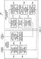
- FIGURE 2 illustrates a flow chart of an example method for virtualization of storage services in an integrated chassis, in accordance with certain embodiments of the present disclosure.
- method 200 may begin at step 202.
- teachings of the present disclosure may be implemented in a variety of configurations of system 100. As such, the preferred initialization point for method 200 and the order of the steps 202-220 comprising method 200 may depend on the implementation chosen.
- a chassis management controller may receive a storage management command (e.g., a storage application programming interface (API) call) from a management console or other interface communicatively coupled to the chassis management controller and encapsulate the storage management command in a datagram (e.g., an Ethernet packet, frame, or other datagram).
- a storage management command e.g., a storage application programming interface (API) call
- API application programming interface
- the chassis management controller may communicate the datagram to a switch management controller (e.g., switch management controller 111). Such communication may be made over a private network of a chassis housing both of the chassis management controller and the switch management controller. In some embodiments, such communication may be made using TCP/IP.
- the switch management controller may extract (e.g., decapsulate) the storage management command from the datagram.
- the storage management controller may identify a storage controller (e.g., a storage controller 114) associated with the command.
- the switch management controller may communicate via an appropriate switch (e.g., a switch 110) an input/output control request based on the storage management command to the identified storage controller.
- the switch management controller may receive from the identified storage controller via an appropriate switch a reply to the input/output control request.
- the switch management controller may encapsulate the storage management command in a datagram (e.g., an Ethernet packet, frame, or other datagram).
- the switch management controller may communicate the datagram to the chassis management controller. Such communication may be made over a private network of a chassis housing both of the chassis management controller and the switch management controller. In some embodiments, such communication may be made using TCP/IP.
- the chassis management controller may extract (e.g., decapsulate) the reply from the datagram.
- the chassis management controller may communicate the reply to the sender (e.g., a management console) of the storage management controller. After completion of step 220, method 200 may end.
- the storage controller 114 may communicate a reply (e.g., a return code) to storage management controller 111, which reply storage management controller 111 may encapsulate into a network datagram (e.g., an Ethernet packet, frame, or other datagram) and communicate such datagram via the private network to a chassis management controller 112.
- the chassis management controller 112 may extract the reply from the datagram and interpret such reply and/or forward the reply to a management console interfaced to the chassis management controller.
- FIGURE 2 discloses a particular number of steps to be taken with respect to method 200, method 200 may be executed with greater or lesser steps than those depicted in FIGURE 2 .
- FIGURE 2 discloses a certain order of steps to be taken with respect to method 200, the steps comprising method 200 may be completed in any suitable order.
- Method 200 may be implemented using system 100, components thereof or any other system operable to implement method 200. In certain embodiments, method 200 may be implemented partially or fully in software and/or firmware embodied in computer-readable media.
Landscapes
- Engineering & Computer Science (AREA)
- Physics & Mathematics (AREA)
- General Engineering & Computer Science (AREA)
- Theoretical Computer Science (AREA)
- Mathematical Physics (AREA)
- Computer Hardware Design (AREA)
- General Physics & Mathematics (AREA)
- Computer Networks & Wireless Communication (AREA)
- Signal Processing (AREA)
- Information Retrieval, Db Structures And Fs Structures Therefor (AREA)
- Selective Calling Equipment (AREA)
- Data Exchanges In Wide-Area Networks (AREA)
Description
- The present disclosure relates in general to information handling systems, and more particularly to virtualization of storage services in an integrated chassis.
- As the value and use of information continues to increase, individuals and businesses seek additional ways to process and store information. One option available to users is information handling systems. An information handling system generally processes, compiles, stores, and/or communicates information or data for business, personal, or other purposes thereby allowing users to take advantage of the value of the information. Because technology and information handling needs and requirements vary between different users or applications, information handling systems may also vary regarding what information is handled, how the information is handled, how much information is processed, stored, or communicated, and how quickly and efficiently the information may be processed, stored, or communicated. The variations in information handling systems allow for information handling systems to be general or configured for a specific user or specific use such as financial transaction processing, airline reservations, enterprise data storage, or global communications. In addition, information handling systems may include a variety of hardware and software components that may be configured to process, store, and communicate information and may include one or more computer systems, data storage systems, and networking systems.
- Existing server architectures either provide a single monolithic server capable of running one operating system and input/output (I/O) resources at a time, or bulky blade server chassis providing multiple servers and I/O control modules in a single chassis. A system chassis with multiple information handling systems with various peripheral and input/output capabilities common to the chassis as a whole may provide advantages, as it allows a blade server chassis in a small form factor, thereby providing a blade server chassis with a size comparable to the size of a monolithic server. Implementation of a system chassis with multiple information handling systems with various peripheral and input/output capabilities common to the chassis as a whole presents numerous challenges.
-
US 2012/063304 A1 concerns manageability tools which are provided for allowing an administrator to have better control over switches in a lossless network of switches. These tools provide the ability to detect slow drain and congestion bottlenecks, detect stuck virtual channels and loss of credits, while hold times on edge ASICs to be different from hold times encore ASICs, and mitigate severe latency bottlenecks. - In accordance with the teachings of the present disclosure, the disadvantages and problems associated with virtualizing storage services in an integrated chassis have been reduced or eliminated.
- In accordance with embodiments of the present disclosure, a system may include a chassis, one or more chassis management controllers housed in the chassis, and a switch management controller. The chassis may be configured to receive a plurality of modular information handling systems. The one or more chassis management controllers may be configured to receive a storage management command, encapsulate the storage management command in a first datagram, and communicate the first datagram to a switch management controller housed in the chassis. The switch management controller may be configured to extract the storage management command from the first datagram, identify a storage controller associated with the storage management command, and communicate an input/output control request to the storage controller based on the storage management command.
- In accordance with these and other embodiments of the present disclosure, a method may include receiving a storage management command at a chassis management controller housed in a chassis configured to receive a plurality of modular information handling systems, encapsulating the storage management command in a first datagram, communicating the first datagram from the chassis management controller to a switch management controller housed in the chassis, extracting the storage management command from the first datagram, identifying a storage controller associated with the storage management command, and communicating an input/output control request from the switch management controller to the storage controller based on the storage management command.
- Technical advantages of the present disclosure will be apparent to those of ordinary skill in the art in view of the following specification, claims, and drawings.
- A more complete understanding of the present embodiments and advantages thereof may be acquired by referring to the following description taken in conjunction with the accompanying drawings, in which like reference numbers indicate like features, and wherein:
-
FIGURE 1 illustrates a block diagram of an example system chassis with multiple information handling systems and with various peripheral and input/output capabilities common to the chassis as a whole, in accordance with certain embodiments of the present disclosure; and -
FIGURE 2 illustrates a flow chart of an example method for virtualization of storage services in an intergrated chassis, in accordance with certain embodiments of the present disclosure. - Preferred embodiments and their advantages are best understood by reference to
FIGURES 1 and2 , wherein like numbers are used to indicate like and corresponding parts. - For the purposes of this disclosure, an information handling system may include any instrumentality or aggregate of instrumentalities operable to compute, classify, process, transmit, receive, retrieve, originate, switch, store, display, manifest, detect, record, reproduce, handle, or utilize any form of information, intelligence, or data for business, scientific, control, entertainment, or other purposes. For example, an information handling system may be a personal computer, a PDA, a consumer electronic device, a network storage device, or any other suitable device and may vary in size, shape, performance, functionality, and price. The information handling system may include memory, one or more processing resources such as a central processing unit (CPU) or hardware or software control logic. Additional components or the information handling system may include one or more storage devices, one or more communications ports for communicating with external devices as well as various input and output (I/O) devices, such as a keyboard, a mouse, and a video display. The information handling system may also include one or more buses operable to transmit communication between the various hardware components.
- For the purposes of this disclosure, information handling resources may broadly refer to any component system, device or apparatus of an information handling system, including without limitation processors, busses, memories, input-output devices and/or interfaces, storage resources, network interfaces, motherboards, electromechanical devices (e.g., fans), displays, and power supplies.
- For the purposes of this disclosure, computer-readable media may include any instrumentality or aggregation of instrumentalities that may retain data and/or instructions for a period of time. Computer-readable media may include, without limitation, storage media such as a direct access storage device (e.g., a hard disk drive or floppy disk), a sequential access storage device (e.g., a tape disk drive), compact disk, CD-ROM, DVD, random access memory (RAM), read-only memory (ROM), electrically erasable programmable read-only memory (EEPROM), and/or flash memory; as well as communications media such wires, optical fibers, microwaves, radio waves, and other electromagnetic and/or optical carriers; and/or any combination of the foregoing.
- Information handling systems often use an array of physical storage resources (e.g., disk drives), such as a Redundant Array of Independent Disks (RAID), for example, for storing information. Arrays of physical storage resources typically utilize multiple disks to perform input and output operations and can be structured to provide redundancy which may increase fault tolerance. Other advantages of arrays of physical storage resources may be increased data integrity, throughput and/or capacity. In operation, one or more physical storage resources disposed in an array of physical storage resources may appear to an operating system as a single logical storage unit or "logical unit." Implementations of physical storage resource arrays can range from a few physical storage resources disposed in a chassis, to hundreds of physical storage resources disposed in one or more separate storage enclosures.
-
FIGURE 1 illustrates a block diagram of anexample system 100 having achassis 101 with multipleinformation handling systems 102 and with various peripheral and input/output capabilities common tochassis 101 as a whole, in accordance with certain embodiments of the present disclosure. As depicted inFIGURE 1 ,system 100 may comprise achassis 101 including a plurality ofinformation handling systems 102, a mid-plane 106, one ormore switches 110, aswitch management controller 111, one or morechassis management controller 112, anetwork interface 116, one ormore slots 120, one ormore cables 124, one ormore storage interfaces 126, adisk drive backplane 128, a plurality ofdisk drives 130, anoptical media drive 132, a keyboard-video-mouse (KVM)interface 134, and a user interface 136. - An
information handling system 102 may generally be operable to receive data from and/or communicate data to one ormore disk drives 130 and/or other information handling resources ofchassis 101 via mid-plane 106. In certain embodiments, aninformation handling system 102 may be a server. In such embodiments, an information handling system may comprise a blade server having modular physical design. In these and other embodiments, aninformation handling system 102 may comprise an M class server. As depicted inFIGURE 1 , aninformation handling system 102 may include aprocessor 103 and one ormore switch interfaces 104 communicatively coupled to theprocessor 103. - A
processor 103 may include any system, device, or apparatus configured to interpret and/or execute program instructions and/or process data, and may include, without limitation a microprocessor, microcontroller, digital signal processor (DSP), application specific integrated circuit (ASIC), or any other digital or analog circuitry configured to interpret and/or execute program instructions and/or process data. In some embodiments,processor 103 may interpret and/or execute program instructions and/or process data stored in a memory, ahard drive 130, and/or another component ofsystem 100. - A
switch interface 104 may comprise any system, device, or apparatus configured to provide an interface between its associatedinformation handling system 102 andswitches 110. In some embodiments,switches 110 may comprise Peripheral Component Interconnect Express (PCIe) switches, in which case aswitch interface 104 may comprise a mezzanine card configured to create a PCIe-compliant interface between its associatedinformation handling system 102 andswitches 110. In other embodiments, aswitch interface 104 may comprise an interposer. Use ofswitch interfaces 104 ininformation handling systems 102 may allow for minimal changes to be made to traditional servers (e.g., M class servers) while supporting the overall system architecture disclosed herein. AlthoughFIGURE 1 depicts an implementation including asingle switch interface 104 perinformation handling system 102, in some embodiments eachinformation handling system 102 may include a plurality ofswitch interfaces 102 for redundancy, high availability, and/or other reasons. - Mid-plane 106 may comprise any system, device, or apparatus configured to interconnect modular
information handling systems 102 with information handling resources ofchassis 101. Accordingly, mid-plane 106 may include slots and/or connectors configured to receiveinformation handling systems 102,switches 110,switch management controller 111,chassis management controllers 112,storage controllers 114,network interface 116,optical media drive 132,KVM interface 134, user interface 136, and/or other information handling resources. In one embodiment, mid-plane 106 may include a single board configured to interconnect modularinformation handling systems 102 with information handling resources. In another embodiment, mid-plane 106 may include multiple boards configured to interconnect modularinformation handling systems 102 with information handling resources. In yet another embodiment, mid-plane 106 may include cabling configured to interconnect modularinformation handling systems 102 with information handling resources. - A
switch 110 may comprise any system, device, or apparatus configured to coupleinformation handling systems 102 to storage controllers 114 (e.g., via mid-plane 106) andslots 120 and perform switching betweeninformation handling systems 102 and various information handling resources ofsystem 100, includingstorage controllers 114 andslots 120. In certain embodiments, aswitch 110 may comprise a PCIe switch. In other embodiments, a switch may comprise a generalized PC bus switch, an Infiniband switch, or other suitable switch. As shown inFIGURE 1 ,chassis 101 may include a plurality ofswitches 110. In such embodiments,switches 110 may operate in a redundant mode for shared devices (e.g.,storage controllers 114 and/or devices coupled to slots 120) and in non-redundant mode for non-shared/zoned devices. As used herein, shared devices may refer to those which may be visible to more than oneinformation handling system 102, while non-shared devices may refer to those which are visible to only a singleinformation handling system 102. - A
chassis management controller 112 may be any system, device, or apparatus configured to facilitate management and/or control ofsystem 100, itsinformation handling systems 102, and/or one or more of its component its component information handling resources. Achassis management controller 102 may be configured to issue commands and/or other signals to manage and/or controlinformation handling system 102 and/or information handling resources ofsystem 100. Achassis management controller 112 may comprise a microprocessor, microcontroller, digital signal processor (DSP), application specific integrated circuit (ASIC), field programmable gate array (FPGA), erasable programmable read-only memory (EPROM), or any combination thereof. As shown inFIGURE 1 , achassis management controller 112 may be coupled tomid-plane 106. Also as shown inFIGURE 1 ,system 100 may include a plurality ofchassis management controllers 112, and in such embodiments,chassis management controllers 112 may be configured as redundant. In some embodiments, achassis management controller 112 may provide a user interface and high level controls for management ofswitches 110, including configuring assignments of individualinformation handling systems 102 to non-shared information handling resources ofsystem 100. In these and other embodiments, a chassis management controller may define configurations of the storage subsystem (e.g.,storage controllers 114, storage interfaces 126, disk drives 130, etc.) ofsystem 100. For example, a chassis management controller may provide physical function configuration and status information that would normally occur at the driver level in traditional server implementations. Examples of physical functions include disk drive discovery and status, RAID configuration and logical volume mapping. - In addition or alternatively, a
chassis management controller 112 may also provide a management console for user/administrator access to these functions. For example, achassis management controller 112 may implement Intelligent Platform Management Interface (IPMI) or another suitable management protocol permitting a user to remotely access achassis management controller 112 to configuresystem 100 and its various information handling resources. In such embodiments, achassis management controller 112 may interface with a network interface separate fromnetwork interface 116, thus allowing for "out-of-band" control of 100, such that communications to and fromchassis management controller 112 are communicated via a management channel physically isolated from an "in band" communication channel withnetwork interface 116. Thus, for example, if a failure occurs insystem 100 that prevents an administrator from interfacing withsystem 100 vianetwork interface 116 and/or user interface 136 (e.g., operating system failure, power failure, etc.), the administrator may still be able to monitor and/or manage system 100 (e.g., to diagnose problems that may have caused failure) via achassis management controller 112. In the same or alternative embodiments,chassis management controller 112 may allow an administrator to remotely manage one or parameters associated with operation ofsystem 100 and its various information handling resources (e.g., power usage, processor allocation, memory allocation, security privileges, etc.). AlthoughFIGURE 1 depicts chassis as having twochassis management controllers 112,chassis 101 may include any suitable numberchassis management controllers 112. - A
storage controller 114 may and include any system, apparatus, or device operable to manage the communication of data between one or more ofinformation handling systems 102 and one or more of disk drives 130. In certain embodiments, astorage controller 114 may provide functionality including, without limitation, disk aggregation and redundancy (e.g., RAID), input/output (I/O) routing, and error detection and recovery. As shown inFIGURE 1 , astorage controller 114 may coupled to a connector onmid-plane 106. Also as shown inFIGURE 1 ,system 100 may include a plurality ofstorage controllers 114, and in such embodiments,storage controllers 114 may be configured as redundant. In addition or in the alternative,storage controllers 114 may in some embodiments be shared among two or moreinformation handling systems 102. As also shown inFIGURE 1 , eachstorage controller 114 may be coupled to one ormore storage interfaces 126 viacables 124. For example, in some embodiments, eachstorage controller 114 may be coupled to a single associatedstorage interface 126 via acable 124. In other embodiments, eachstorage controller 114 may be coupled to two ormore storage interfaces 126 via a plurality ofcables 124, thus permitting redundancy as shown inFIGURE 1 .Storage controllers 114 may also have features supporting shared storage and high availability. For example, in PCIe implementations, a unique PCIe identifier may be used to indicate shared storage capability and compatibility insystem 100. - In embodiments in which switches 110 comprise PCIe switches or switches configured in accordance with another communication standard,
chassis management controllers 112 may not be able to communicate directly withswitches 110. Availablechassis management controllers 112 may not be configured in accordance with PCIe or other communication standards available inswitches 110, and it may not be desirable to create a proprietarychassis management controller 112 configured in accordance with PCIe or such other communication standards for use insystem 100 due to cost concerns. Accordingly, challenges may exist in enabling management functionality of storage devices (e.g., disk drives 130) viachassis management controllers 112 as direct PCIe communications (or communications via another communication protocol) may not be available between - Accordingly, a
switch management controller 111 may be communicatively interfaced betweenchassis management controllers 112 and switches 110, and configured to virtualize management communications betweenchassis management controllers 112 andswitches 110 related to management of storage components (e.g.,storage controllers 114, disk drives 130) and/or other components ofsystem 100.Switch management controller 111 may, in some embodiments, interface withswitches 110 via a private network (e.g., an Ethernet network) internal tochassis 101. In such embodiments, eachswitch 110 andswitch management controller 111 may establish a Transmission Control Protocol/Internet Protocol (TCP/IP) socket for communication. In these and other embodiments,switch management controller 111 may comprise a power PC management processor or processor similar in structure and/or function. - In operation, a
chassis management controller 112 may receive a storage management command (e.g., a storage application programming interface (API) call) from a management console or other interface.Chassis management controller 112 may encapsulate such command in a network datagram (e.g., an Ethernet packet, frame, or other datagram) and communicate such datagram via the private network to switchmanagement controller 111.Switch management controller 111 may receive such datagram and extract the command from the datagram. Based on analysis of the command,storage management controller 111 may identify astorage controller 114 associated with the command and execute an input/output control request tosuch storage controller 114 via anappropriate switch 110. Thestorage controller 114 may communicate a reply (e.g., a return code) via an appropriate switch tostorage management controller 111, which replystorage management controller 111 may encapsulate into a network datagram (e.g., an Ethernet packet, frame, or other datagram) and communicate such datagram via the private network to achassis management controller 112. Thechassis management controller 112 may extract the reply from the datagram and interpret such reply and/or forward the reply to a management console interfaced to the chassis management controller. - As depicted in
FIGURE 1 , aswitch 110 may have coupled thereto one ormore slots 120. Aslot 120 may include any system, device, or apparatus configured to allow addition of one or more expansion cards tochassis 101 in order to electrically coupled such expansion cards to aswitch 110.Such slots 120 may comprise any suitable combination of full-height risers, full-height slots, and low-profile slots. A full-height riser may include any system, device, or apparatus configured to allow addition of one or more expansion cards (e.g., a full-height slot) having a physical profile or form factor with dimensions that practically prevent such expansion cards to be coupled in a particular manner (e.g., perpendicularly) tomid-plane 106 and/or switch 110 (e.g., the proximity of information handling resources inchassis 101 prevents physical placement of an expansion card in such manner). Accordingly, a full-height riser may itself physically couple with a low-profile to mid-plane 106, aswitch 110, or another components, and full-height cards may then be coupled to full-height slots of full-height riser. On the other hand, low-profile slots may be configured to couple low-profile expansion cards toswitches 110 without the need for a full-height riser. -
Slots 120 may also include electrically conductive elements (e.g., edge connectors, traces, etc.) allowing for expansion cards inserted intoslots 120 to be electrically coupled to switches 110. In operation, switches 110 may manage switching of communications between individualinformation handling systems 102 and expansion cards coupled toslots 120. In some embodiments,slots 120 may be nonshared (e.g., eachslot 120 is associated with a single information handling system 102). In other embodiments, one or more ofslots 120 may be shared among two or moreinformation handling systems 102. In these and other embodiments, one ormore slots 120 may be configured to be compatible with PCIe, generalized PC bus switch, Infiniband, or other suitable communication specification, standard, or protocol. -
Network interface 116 may include any suitable system, apparatus, or device operable to serve as an interface betweenchassis 101 and an external network (e.g., a local area network or other network).Network interface 116 may enableinformation handling systems 102 to communicate with the external network using any suitable transmission protocol (e.g., TCP/IP) and/or standard (e.g., IEEE 802.11, Wi-Fi). In certain embodiments,network interface 116 may include a network interface card (NIC). In the same or alternative embodiments,network interface 116 may be configured to communicate via wireless transmissions. In the same or alternative embodiments,network interface 116 may provide physical access to a networking medium and/or provide a low-level addressing system (e.g., through the use of Media Access Control addresses). In some embodiments,network interface 116 may be implemented as a local area network (LAN) on motherboard (LOM) interface. - In some embodiments, various components of
chassis 101 may be coupled to a planar. For example, a planar may interconnectswitches 110,chassis management controller 112,storage controllers 114,network interface 116, optical media drive 132,KVM interface 134, user interface 136, and/or other modular information handling resources ofchassis 101 to mid-plane 106 ofsystem 100. Accordingly, such planar may include slots and/or connectors configured to interconnect with such information handling resources. - Storage interfaces 126 may include any system, device, or apparatus configured to facilitate communication between
storage controllers 114 and disk drives 130. For example, a storage interface may serve to permit a relatively small number of communication links (e.g., two) betweenstorage controllers 114 andstorage interfaces 126 to communicate with a greater number of disk drives 130. Thus, astorage interface 126 may provide a switching mechanism and/or disk drive addressing mechanism that allows aninformation handling system 102 to communicate withnumerous disk drives 130 via a limited number of communication links and/or channels. Accordingly, astorage interface 126 may operate like an Ethernet hub or network switch that allows multiple systems to be coupled using a single switch port (or relatively few switch ports). Astorage interface 126 may be implemented as an expander (e.g., a Serial Attached SCSI (SAS) expander), an Ethernet switch, a FibreChannel switch, Internet Small Computer System Interface (iSCSI) switch, or any other suitable switch. In order to support high availability storage,system 100 may implement a plurality of redundant storage interfaces 126, as shown inFIGURE 1 . -
Disk drive backplane 128 may comprise any system, device, or apparatus configured to interconnectmodular storage interfaces 126 with modular disk drives 130. Accordingly,disk drive backplane 128 may include slots and/or connectors configured to receivestorage interfaces 126 and/or disk drives 130. In some embodiments,system 100 may include two or more backplanes, in order to support differently-sized disk drive form factors. To support redundancy and high availability, abackplane 128 may be configured to receive a plurality (e.g., 2) ofstorage interfaces 126 which couple twostorage controllers 114 to eachdisk drive 130. - Each
disk drive 130 may include computer-readable media (e.g., magnetic storage media, optical storage media, opto-magnetic storage media, and/or other type of rotating storage media, flash memory, and/or other type of solid state storage media) and may be generally operable to store data and/or programs (e.g., one or more operating systems and/or one or more application programs). Althoughdisk drives 130 are depicted as being internal tochassis 101 inFIGURE 1 , in some embodiments, one or more disk drives may be located external to chassis 101 (e.g., in one or more enclosures external to chassis 101). - Optical media drive 132 may be coupled to
mid-plane 106 and may include any suitable system, apparatus, or device configured to read data from and/or write data to an optical storage medium (e.g., a compact disc (CD), digital versatile disc (DVD), blue laser medium, and/or other optical medium). In certain embodiments, optical media drive 132 may use laser light or other electromagnetic energy to read and/or write data to an optical storage medium. In some embodiments, optical media drive 132 may be nonshared and may be user-configurable such that optical media drive 132 is associated with a singleinformation handling system 102. -
KVM interface 134 may be coupled tomid-plane 106 and may include any suitable system, apparatus, or device configured to couple to one or more of a keyboard, video display, and mouse and act as switch between multipleinformation handling systems 102 and the keyboard, video display, and/or mouse, thus allowing a user to interface with a plurality ofinformation handling systems 102 via a single keyboard, video display, and/or mouse. - User interface 136 may include any system, apparatus, or device via which a user may interact with
system 100 and its various information handling resources by facilitating input from a user allowing the user to manipulatesystem 100 and output to auser allowing system 100 to indicate effects of the user's manipulation. For example, user interface 136 may include a display suitable for creating graphic images and/or alphanumeric characters recognizable to a user, and may include, for example, a liquid crystal display (LCD), cathode ray tube (CRT), a plasma screen, and/or a digital light processor (DLP) projection monitor. In certain embodiments, such a display may be an integral part ofchassis 101 and receive power from power supplies (not explicitly shown) ofchassis 101, rather than being coupled tochassis 101 via a cable. In some embodiments, such display may comprise a touch screen device capable of receiving user input, wherein a touch sensor may be mechanically coupled or overlaid upon the display and may comprise any system, apparatus, or device suitable for defecting the presence and/or location of a tactile touch, including, for example, a resistive sensor, capacitive sensor, surface acoustic wave sensor, projected capacitance sensor, infrared sensor, strain gauge sensor, optical imaging sensor, dispersive signal technology sensor, and/or acoustic pulse recognition sensor. In these and other embodiments, user interface 136 may include other user interface elements (e.g., a keypad, buttons, and/or switches placed in proximity to a display) allowing a user to provide input tosystem 100. User interface 136 may be coupled tochassis management controllers 112 and/or other components ofsystem 100, and thus may allow a user to configure various information handling resources of system 100 (e.g., assign individualinformation handling systems 102 to particular information handling resources). -
FIGURE 2 illustrates a flow chart of an example method for virtualization of storage services in an integrated chassis, in accordance with certain embodiments of the present disclosure. According to certain embodiments,method 200 may begin atstep 202. As noted above, teachings of the present disclosure may be implemented in a variety of configurations ofsystem 100. As such, the preferred initialization point formethod 200 and the order of the steps 202-220 comprisingmethod 200 may depend on the implementation chosen. - At
step 202, a chassis management controller (e.g., a chassis management controller 112) may receive a storage management command (e.g., a storage application programming interface (API) call) from a management console or other interface communicatively coupled to the chassis management controller and encapsulate the storage management command in a datagram (e.g., an Ethernet packet, frame, or other datagram). - At
step 204, the chassis management controller may communicate the datagram to a switch management controller (e.g., switch management controller 111). Such communication may be made over a private network of a chassis housing both of the chassis management controller and the switch management controller. In some embodiments, such communication may be made using TCP/IP. - At
step 206, the switch management controller may extract (e.g., decapsulate) the storage management command from the datagram. Atstep 208, based on analysis of the command, the storage management controller may identify a storage controller (e.g., a storage controller 114) associated with the command. Atstep 210, the switch management controller may communicate via an appropriate switch (e.g., a switch 110) an input/output control request based on the storage management command to the identified storage controller. - At step 212, the switch management controller may receive from the identified storage controller via an appropriate switch a reply to the input/output control request. At
step 214, the switch management controller may encapsulate the storage management command in a datagram (e.g., an Ethernet packet, frame, or other datagram). Atstep 216, the switch management controller may communicate the datagram to the chassis management controller. Such communication may be made over a private network of a chassis housing both of the chassis management controller and the switch management controller. In some embodiments, such communication may be made using TCP/IP. - At
step 218, the chassis management controller may extract (e.g., decapsulate) the reply from the datagram. Atstep 220, the chassis management controller may communicate the reply to the sender (e.g., a management console) of the storage management controller. After completion ofstep 220,method 200 may end. - The
storage controller 114 may communicate a reply (e.g., a return code) tostorage management controller 111, which replystorage management controller 111 may encapsulate into a network datagram (e.g., an Ethernet packet, frame, or other datagram) and communicate such datagram via the private network to achassis management controller 112. Thechassis management controller 112 may extract the reply from the datagram and interpret such reply and/or forward the reply to a management console interfaced to the chassis management controller. - Although
FIGURE 2 discloses a particular number of steps to be taken with respect tomethod 200,method 200 may be executed with greater or lesser steps than those depicted inFIGURE 2 . In addition, althoughFIGURE 2 discloses a certain order of steps to be taken with respect tomethod 200, thesteps comprising method 200 may be completed in any suitable order. -
Method 200 may be implemented usingsystem 100, components thereof or any other system operable to implementmethod 200. In certain embodiments,method 200 may be implemented partially or fully in software and/or firmware embodied in computer-readable media.
Claims (15)
- A system (100) comprising:a chassis (101) configured to receive a plurality of modular information handling systems (102);one or more chassis management controllers (112) housed in the chassis (101) and configured to:receive (202) a storage management command;characterized in that the one or more chassis management controllers (112) housed in the chassis (101) are further configured to:encapsulate the storage management command in a first datagram; andcommunicate (204) the first datagram to a switch management controller (111) housed in the chassis (101); andthe switch management controller (111) configured to:extract (206) the storage management command from the first datagram;identify (208) a storage controller (114) associated with the storage management command; andcommunicate (210) an input/output control request to the storage controller (114) based on the storage management command.
- A system according to Claim 1, the command originating from a management console communicatively coupled to the one or more chassis management controllers (112).
- A system according to Claim 1, the datagram comprising an Ethernet frame.
- A system according to Claim 1, the one or more chassis management controllers (112) configured to communicate the first datagram to the switch management controller (111) via Transmission Control Protocol/Internet Protocol or via a private network internal to the chassis (101).
- A system according to Claim 1, the switch management controller (111) configured to communicate the input/output control request to the storage controller (114) via a switch (110).
- A system according to Claim 5, the switch (110) compliant with Peripheral Component Interconnect Express.
- A system according to Claim 1, the switch management controller (111) further configured to:receive (212) a reply to the input/output control request from the storage controller (114);encapsulate (214) the reply in a second datagram; andcommunicate (216) the second datagram to the one or more chassis management controllers (112).
- A system according to Claim 7, the chassis management controller (112) further configured to:extract (218) the reply from the second datagram; andcommunicate (220) the reply to an originator of the storage management command.
- A method comprising:Receiving (202) a storage management command at a chassis management controller (112) housed in a chassis (101) configured to receive a plurality of modular information handling systems (102);characterized in that the method further comprises:encapsulating the storage management command in a first datagram;communicating (204) the first datagram from the chassis management controller (112) to a switch management controller (111) housed in the chassis (101);extracting (206) the storage management command from the first datagram;identifying (208) a storage controller (114) associated with the storage management command; andcommunicating (210) an input/output control request from the switch management controller (111) to the storage controller (114) based on the storage management command.
- A method according to Claim 9, the command originating from a management console communicatively coupled to the chassis management controller (112).
- A method according to Claim 9, the datagram comprising an Ethernet frame.
- A method according to Claim 9, wherein communicating the first datagram comprises communicating the first datagram via Transmission Control Protocol/Internet Protocol or via a private network internal to the chassis (101).
- A method according to Claim 9, wherein communicating the input/output control request comprises communicating the input/output control request to the storage controller (114) via a switch (110).
- A method according to Claim 9, further comprising:receiving (212) a reply to the input/output control request from the storage controller (114);encapsulating (214) the reply in a second datagram; andcommunicating (216) the second datagram from the switch management controller (111) to the chassis management controller (112).
- A method according to Claim 14, further comprising:extracting (218) the reply from the second datagram; andcommunicating (220) the reply to an originator of the storage management command.
Applications Claiming Priority (2)
| Application Number | Priority Date | Filing Date | Title |
|---|---|---|---|
| US13/442,727 US8838871B2 (en) | 2012-04-09 | 2012-04-09 | Methods and systems for virtualization of storage services in an integrated chassis |
| PCT/US2013/035228 WO2013154900A1 (en) | 2012-04-09 | 2013-04-04 | Methods and systems for virtualization of storage services in an integrated chassis |
Publications (2)
| Publication Number | Publication Date |
|---|---|
| EP2837149A1 EP2837149A1 (en) | 2015-02-18 |
| EP2837149B1 true EP2837149B1 (en) | 2016-03-30 |
Family
ID=48143380
Family Applications (1)
| Application Number | Title | Priority Date | Filing Date |
|---|---|---|---|
| EP13717921.4A Active EP2837149B1 (en) | 2012-04-09 | 2013-04-04 | Methods and systems for virtualization of storage services in an integrated chassis |
Country Status (5)
| Country | Link |
|---|---|
| US (2) | US8838871B2 (en) |
| EP (1) | EP2837149B1 (en) |
| CN (1) | CN104247353B (en) |
| IN (1) | IN2014DN08018A (en) |
| WO (1) | WO2013154900A1 (en) |
Families Citing this family (5)
| Publication number | Priority date | Publication date | Assignee | Title |
|---|---|---|---|---|
| CN105335308B (en) * | 2014-05-30 | 2018-07-03 | 华为技术有限公司 | To access information treating method and apparatus, the system of storage device |
| US9898375B1 (en) | 2015-12-22 | 2018-02-20 | EMC IP Holding Company LLC | Asymmetric memory transceiver |
| US10235314B2 (en) | 2015-12-28 | 2019-03-19 | EMC IP Holding Company LLC | Fabric for modular solid-state storage systems |
| US10034407B2 (en) * | 2016-07-22 | 2018-07-24 | Intel Corporation | Storage sled for a data center |
| US10303568B2 (en) * | 2017-02-10 | 2019-05-28 | Dell Products L.P. | Systems and methods for high availability of management controllers |
Family Cites Families (16)
| Publication number | Priority date | Publication date | Assignee | Title |
|---|---|---|---|---|
| US6018779A (en) * | 1997-12-15 | 2000-01-25 | Emc Corporation | System for encapsulating a plurality of selected commands within a single command and transmitting the single command to a remote device over a communication link therewith |
| US6980543B1 (en) | 1998-06-19 | 2005-12-27 | Juniper Networks, Inc. | Interconnect network for operation within a communication node |
| US6985431B1 (en) | 1999-08-27 | 2006-01-10 | International Business Machines Corporation | Network switch and components and method of operation |
| US6604155B1 (en) * | 1999-11-09 | 2003-08-05 | Sun Microsystems, Inc. | Storage architecture employing a transfer node to achieve scalable performance |
| US6876656B2 (en) * | 2001-06-15 | 2005-04-05 | Broadcom Corporation | Switch assisted frame aliasing for storage virtualization |
| US6788690B2 (en) * | 2002-06-27 | 2004-09-07 | Nokia Corporation | Packet identifier search filtering |
| US7360010B2 (en) * | 2003-04-14 | 2008-04-15 | Copan Systems, Inc. | Method and apparatus for storage command and data router |
| CN1323358C (en) * | 2004-03-05 | 2007-06-27 | 中国科学院计算技术研究所 | Virtual storing model and method thereof |
| US7676666B2 (en) * | 2006-02-02 | 2010-03-09 | Dell Products L.P. | Virtual BIOS firmware hub |
| JP4901310B2 (en) * | 2006-05-31 | 2012-03-21 | 株式会社日立製作所 | Storage control device and command execution number control method for storage control device |
| US7788717B2 (en) * | 2006-11-02 | 2010-08-31 | International Business Machines Corporation | Apparatus, system, and method for selectively enabling a power-on password |
| US9244502B2 (en) * | 2007-09-29 | 2016-01-26 | Dell Products L.P. | Methods and systems for managing network attached storage (NAS) within a management subsystem |
| US7787454B1 (en) * | 2007-10-31 | 2010-08-31 | Gigamon Llc. | Creating and/or managing meta-data for data storage devices using a packet switch appliance |
| US8296514B2 (en) * | 2007-12-20 | 2012-10-23 | International Business Machines Corporation | Automated correction of contentious storage virtualization configurations |
| CN102244653B (en) * | 2010-05-14 | 2014-07-23 | 杭州华三通信技术有限公司 | Dynamic maintenance method and system for storage virtualization |
| US8599691B2 (en) | 2010-09-14 | 2013-12-03 | Brocade Communications Systems, Inc. | Manageability tools for lossless networks |
-
2012
- 2012-04-09 US US13/442,727 patent/US8838871B2/en active Active
-
2013
- 2013-04-04 IN IN8018DEN2014 patent/IN2014DN08018A/en unknown
- 2013-04-04 CN CN201380021127.5A patent/CN104247353B/en active Active
- 2013-04-04 EP EP13717921.4A patent/EP2837149B1/en active Active
- 2013-04-04 WO PCT/US2013/035228 patent/WO2013154900A1/en active Application Filing
-
2014
- 2014-08-18 US US14/462,153 patent/US9519607B2/en active Active
Also Published As
| Publication number | Publication date |
|---|---|
| US9519607B2 (en) | 2016-12-13 |
| CN104247353A (en) | 2014-12-24 |
| CN104247353B (en) | 2017-07-14 |
| US20130268714A1 (en) | 2013-10-10 |
| US8838871B2 (en) | 2014-09-16 |
| EP2837149A1 (en) | 2015-02-18 |
| US20140359194A1 (en) | 2014-12-04 |
| WO2013154900A1 (en) | 2013-10-17 |
| IN2014DN08018A (en) | 2015-05-01 |
Similar Documents
| Publication | Publication Date | Title |
|---|---|---|
| US9471234B2 (en) | Systems and methods for mirroring virtual functions in a chassis configured to receive a plurality of modular information handling systems and a plurality of modular information handling resources | |
| US10261803B2 (en) | Systems and methods for in-situ fabric link optimization in a modular information handling system chassis | |
| US10430351B2 (en) | Systems and methods for virtual service processor data bridging | |
| US9092022B2 (en) | Systems and methods for load balancing of modular information handling resources in a chassis | |
| US10498645B2 (en) | Live migration of virtual machines using virtual bridges in a multi-root input-output virtualization blade chassis | |
| US8694693B2 (en) | Methods and systems for providing user selection of associations between information handling resources and information handling systems in an integrated chassis | |
| US9690745B2 (en) | Methods and systems for removal of information handling resources in a shared input/output infrastructure | |
| US8819779B2 (en) | Methods and systems for managing multiple information handling systems with a virtual keyboard-video-mouse interface | |
| US20140006676A1 (en) | Systems and methods for dynamic allocation of information handling resources | |
| US9864719B2 (en) | Systems and methods for power optimization at input/output nodes of an information handling system | |
| US9772652B2 (en) | Systems and methods for distributing and synchronizing real-time clock | |
| US20130265328A1 (en) | Methods and systems for providing video overlay for display coupled to integrated chassis housing a plurality of modular information handling systems | |
| US10157074B2 (en) | Systems and methods for multi-root input/output virtualization-based management by single service processor | |
| US9519607B2 (en) | Methods and systems for virtualization of storage services in an integrated chassis | |
| US20140149658A1 (en) | Systems and methods for multipath input/output configuration | |
| US20170336856A1 (en) | Systems and methods for autonomously adapting powering budgeting in a multi-information handling system passive chassis environment | |
| US8935555B2 (en) | Wake-on-local-area-network operations in a modular chassis using a virtualized input-output-virtualization environment | |
| US9092583B2 (en) | Systems and methods for communication between modular information handling systems in a chassis | |
| US10437303B2 (en) | Systems and methods for chassis-level view of information handling system power capping |
Legal Events
| Date | Code | Title | Description |
|---|---|---|---|
| PUAI | Public reference made under article 153(3) epc to a published international application that has entered the european phase |
Free format text: ORIGINAL CODE: 0009012 |
|
| 17P | Request for examination filed |
Effective date: 20141027 |
|
| AK | Designated contracting states |
Kind code of ref document: A1 Designated state(s): AL AT BE BG CH CY CZ DE DK EE ES FI FR GB GR HR HU IE IS IT LI LT LU LV MC MK MT NL NO PL PT RO RS SE SI SK SM TR |
|
| AX | Request for extension of the european patent |
Extension state: BA ME |
|
| DAX | Request for extension of the european patent (deleted) | ||
| GRAP | Despatch of communication of intention to grant a patent |
Free format text: ORIGINAL CODE: EPIDOSNIGR1 |
|
| INTG | Intention to grant announced |
Effective date: 20151029 |
|
| GRAS | Grant fee paid |
Free format text: ORIGINAL CODE: EPIDOSNIGR3 |
|
| GRAA | (expected) grant |
Free format text: ORIGINAL CODE: 0009210 |
|
| AK | Designated contracting states |
Kind code of ref document: B1 Designated state(s): AL AT BE BG CH CY CZ DE DK EE ES FI FR GB GR HR HU IE IS IT LI LT LU LV MC MK MT NL NO PL PT RO RS SE SI SK SM TR |
|
| REG | Reference to a national code |
Ref country code: GB Ref legal event code: FG4D |
|
| REG | Reference to a national code |
Ref country code: CH Ref legal event code: EP |
|
| REG | Reference to a national code |
Ref country code: AT Ref legal event code: REF Ref document number: 786461 Country of ref document: AT Kind code of ref document: T Effective date: 20160415 |
|
| REG | Reference to a national code |
Ref country code: IE Ref legal event code: FG4D |
|
| REG | Reference to a national code |
Ref country code: DE Ref legal event code: R096 Ref document number: 602013005978 Country of ref document: DE |
|
| REG | Reference to a national code |
Ref country code: LT Ref legal event code: MG4D |
|
| PG25 | Lapsed in a contracting state [announced via postgrant information from national office to epo] |
Ref country code: NO Free format text: LAPSE BECAUSE OF FAILURE TO SUBMIT A TRANSLATION OF THE DESCRIPTION OR TO PAY THE FEE WITHIN THE PRESCRIBED TIME-LIMIT Effective date: 20160630 Ref country code: GR Free format text: LAPSE BECAUSE OF FAILURE TO SUBMIT A TRANSLATION OF THE DESCRIPTION OR TO PAY THE FEE WITHIN THE PRESCRIBED TIME-LIMIT Effective date: 20160701 Ref country code: HR Free format text: LAPSE BECAUSE OF FAILURE TO SUBMIT A TRANSLATION OF THE DESCRIPTION OR TO PAY THE FEE WITHIN THE PRESCRIBED TIME-LIMIT Effective date: 20160330 Ref country code: FI Free format text: LAPSE BECAUSE OF FAILURE TO SUBMIT A TRANSLATION OF THE DESCRIPTION OR TO PAY THE FEE WITHIN THE PRESCRIBED TIME-LIMIT Effective date: 20160330 |
|
| REG | Reference to a national code |
Ref country code: NL Ref legal event code: MP Effective date: 20160330 |
|
| REG | Reference to a national code |
Ref country code: AT Ref legal event code: MK05 Ref document number: 786461 Country of ref document: AT Kind code of ref document: T Effective date: 20160330 |
|
| PG25 | Lapsed in a contracting state [announced via postgrant information from national office to epo] |
Ref country code: SE Free format text: LAPSE BECAUSE OF FAILURE TO SUBMIT A TRANSLATION OF THE DESCRIPTION OR TO PAY THE FEE WITHIN THE PRESCRIBED TIME-LIMIT Effective date: 20160330 Ref country code: LV Free format text: LAPSE BECAUSE OF FAILURE TO SUBMIT A TRANSLATION OF THE DESCRIPTION OR TO PAY THE FEE WITHIN THE PRESCRIBED TIME-LIMIT Effective date: 20160330 Ref country code: BE Free format text: LAPSE BECAUSE OF NON-PAYMENT OF DUE FEES Effective date: 20160430 Ref country code: LT Free format text: LAPSE BECAUSE OF FAILURE TO SUBMIT A TRANSLATION OF THE DESCRIPTION OR TO PAY THE FEE WITHIN THE PRESCRIBED TIME-LIMIT Effective date: 20160330 Ref country code: RS Free format text: LAPSE BECAUSE OF FAILURE TO SUBMIT A TRANSLATION OF THE DESCRIPTION OR TO PAY THE FEE WITHIN THE PRESCRIBED TIME-LIMIT Effective date: 20160330 |
|
| PG25 | Lapsed in a contracting state [announced via postgrant information from national office to epo] |
Ref country code: NL Free format text: LAPSE BECAUSE OF FAILURE TO SUBMIT A TRANSLATION OF THE DESCRIPTION OR TO PAY THE FEE WITHIN THE PRESCRIBED TIME-LIMIT Effective date: 20160330 |
|
| PG25 | Lapsed in a contracting state [announced via postgrant information from national office to epo] |
Ref country code: PL Free format text: LAPSE BECAUSE OF FAILURE TO SUBMIT A TRANSLATION OF THE DESCRIPTION OR TO PAY THE FEE WITHIN THE PRESCRIBED TIME-LIMIT Effective date: 20160330 Ref country code: EE Free format text: LAPSE BECAUSE OF FAILURE TO SUBMIT A TRANSLATION OF THE DESCRIPTION OR TO PAY THE FEE WITHIN THE PRESCRIBED TIME-LIMIT Effective date: 20160330 Ref country code: IS Free format text: LAPSE BECAUSE OF FAILURE TO SUBMIT A TRANSLATION OF THE DESCRIPTION OR TO PAY THE FEE WITHIN THE PRESCRIBED TIME-LIMIT Effective date: 20160730 |
|
| PG25 | Lapsed in a contracting state [announced via postgrant information from national office to epo] |
Ref country code: SK Free format text: LAPSE BECAUSE OF FAILURE TO SUBMIT A TRANSLATION OF THE DESCRIPTION OR TO PAY THE FEE WITHIN THE PRESCRIBED TIME-LIMIT Effective date: 20160330 Ref country code: RO Free format text: LAPSE BECAUSE OF FAILURE TO SUBMIT A TRANSLATION OF THE DESCRIPTION OR TO PAY THE FEE WITHIN THE PRESCRIBED TIME-LIMIT Effective date: 20160330 Ref country code: PT Free format text: LAPSE BECAUSE OF FAILURE TO SUBMIT A TRANSLATION OF THE DESCRIPTION OR TO PAY THE FEE WITHIN THE PRESCRIBED TIME-LIMIT Effective date: 20160801 Ref country code: SM Free format text: LAPSE BECAUSE OF FAILURE TO SUBMIT A TRANSLATION OF THE DESCRIPTION OR TO PAY THE FEE WITHIN THE PRESCRIBED TIME-LIMIT Effective date: 20160330 Ref country code: CZ Free format text: LAPSE BECAUSE OF FAILURE TO SUBMIT A TRANSLATION OF THE DESCRIPTION OR TO PAY THE FEE WITHIN THE PRESCRIBED TIME-LIMIT Effective date: 20160330 Ref country code: ES Free format text: LAPSE BECAUSE OF FAILURE TO SUBMIT A TRANSLATION OF THE DESCRIPTION OR TO PAY THE FEE WITHIN THE PRESCRIBED TIME-LIMIT Effective date: 20160330 Ref country code: AT Free format text: LAPSE BECAUSE OF FAILURE TO SUBMIT A TRANSLATION OF THE DESCRIPTION OR TO PAY THE FEE WITHIN THE PRESCRIBED TIME-LIMIT Effective date: 20160330 |
|
| REG | Reference to a national code |
Ref country code: CH Ref legal event code: PL |
|
| PG25 | Lapsed in a contracting state [announced via postgrant information from national office to epo] |
Ref country code: IT Free format text: LAPSE BECAUSE OF FAILURE TO SUBMIT A TRANSLATION OF THE DESCRIPTION OR TO PAY THE FEE WITHIN THE PRESCRIBED TIME-LIMIT Effective date: 20160330 Ref country code: BE Free format text: LAPSE BECAUSE OF FAILURE TO SUBMIT A TRANSLATION OF THE DESCRIPTION OR TO PAY THE FEE WITHIN THE PRESCRIBED TIME-LIMIT Effective date: 20160330 |
|
| REG | Reference to a national code |
Ref country code: DE Ref legal event code: R097 Ref document number: 602013005978 Country of ref document: DE |
|
| REG | Reference to a national code |
Ref country code: IE Ref legal event code: MM4A |
|
| PG25 | Lapsed in a contracting state [announced via postgrant information from national office to epo] |
Ref country code: LI Free format text: LAPSE BECAUSE OF NON-PAYMENT OF DUE FEES Effective date: 20160430 Ref country code: CH Free format text: LAPSE BECAUSE OF NON-PAYMENT OF DUE FEES Effective date: 20160430 Ref country code: DK Free format text: LAPSE BECAUSE OF FAILURE TO SUBMIT A TRANSLATION OF THE DESCRIPTION OR TO PAY THE FEE WITHIN THE PRESCRIBED TIME-LIMIT Effective date: 20160330 |
|
| PLBE | No opposition filed within time limit |
Free format text: ORIGINAL CODE: 0009261 |
|
| STAA | Information on the status of an ep patent application or granted ep patent |
Free format text: STATUS: NO OPPOSITION FILED WITHIN TIME LIMIT |
|
| 26N | No opposition filed |
Effective date: 20170103 |
|
| REG | Reference to a national code |
Ref country code: FR Ref legal event code: ST Effective date: 20170215 |
|
| PG25 | Lapsed in a contracting state [announced via postgrant information from national office to epo] |
Ref country code: FR Free format text: LAPSE BECAUSE OF NON-PAYMENT OF DUE FEES Effective date: 20160530 |
|
| PG25 | Lapsed in a contracting state [announced via postgrant information from national office to epo] |
Ref country code: IE Free format text: LAPSE BECAUSE OF NON-PAYMENT OF DUE FEES Effective date: 20160404 Ref country code: SI Free format text: LAPSE BECAUSE OF FAILURE TO SUBMIT A TRANSLATION OF THE DESCRIPTION OR TO PAY THE FEE WITHIN THE PRESCRIBED TIME-LIMIT Effective date: 20160330 |
|
| PG25 | Lapsed in a contracting state [announced via postgrant information from national office to epo] |
Ref country code: HU Free format text: LAPSE BECAUSE OF FAILURE TO SUBMIT A TRANSLATION OF THE DESCRIPTION OR TO PAY THE FEE WITHIN THE PRESCRIBED TIME-LIMIT; INVALID AB INITIO Effective date: 20130404 |
|
| PG25 | Lapsed in a contracting state [announced via postgrant information from national office to epo] |
Ref country code: CY Free format text: LAPSE BECAUSE OF FAILURE TO SUBMIT A TRANSLATION OF THE DESCRIPTION OR TO PAY THE FEE WITHIN THE PRESCRIBED TIME-LIMIT Effective date: 20160330 Ref country code: LU Free format text: LAPSE BECAUSE OF NON-PAYMENT OF DUE FEES Effective date: 20160404 Ref country code: MK Free format text: LAPSE BECAUSE OF FAILURE TO SUBMIT A TRANSLATION OF THE DESCRIPTION OR TO PAY THE FEE WITHIN THE PRESCRIBED TIME-LIMIT Effective date: 20160330 Ref country code: MC Free format text: LAPSE BECAUSE OF FAILURE TO SUBMIT A TRANSLATION OF THE DESCRIPTION OR TO PAY THE FEE WITHIN THE PRESCRIBED TIME-LIMIT Effective date: 20160330 Ref country code: MT Free format text: LAPSE BECAUSE OF NON-PAYMENT OF DUE FEES Effective date: 20160430 |
|
| PG25 | Lapsed in a contracting state [announced via postgrant information from national office to epo] |
Ref country code: BG Free format text: LAPSE BECAUSE OF FAILURE TO SUBMIT A TRANSLATION OF THE DESCRIPTION OR TO PAY THE FEE WITHIN THE PRESCRIBED TIME-LIMIT Effective date: 20160330 |
|
| PG25 | Lapsed in a contracting state [announced via postgrant information from national office to epo] |
Ref country code: TR Free format text: LAPSE BECAUSE OF FAILURE TO SUBMIT A TRANSLATION OF THE DESCRIPTION OR TO PAY THE FEE WITHIN THE PRESCRIBED TIME-LIMIT Effective date: 20160330 Ref country code: AL Free format text: LAPSE BECAUSE OF FAILURE TO SUBMIT A TRANSLATION OF THE DESCRIPTION OR TO PAY THE FEE WITHIN THE PRESCRIBED TIME-LIMIT Effective date: 20160330 |
|
| REG | Reference to a national code |
Ref country code: DE Ref legal event code: R079 Ref document number: 602013005978 Country of ref document: DE Free format text: PREVIOUS MAIN CLASS: H04L0012933000 Ipc: H04L0049100000 |
|
| P01 | Opt-out of the competence of the unified patent court (upc) registered |
Effective date: 20230528 |
|
| PGFP | Annual fee paid to national office [announced via postgrant information from national office to epo] |
Ref country code: GB Payment date: 20240320 Year of fee payment: 12 |
|
| PGFP | Annual fee paid to national office [announced via postgrant information from national office to epo] |
Ref country code: DE Payment date: 20240320 Year of fee payment: 12 |