EP2837136B1 - Analytik von netzwerkverfügbarkeit - Google Patents
Analytik von netzwerkverfügbarkeit Download PDFInfo
- Publication number
- EP2837136B1 EP2837136B1 EP13717403.3A EP13717403A EP2837136B1 EP 2837136 B1 EP2837136 B1 EP 2837136B1 EP 13717403 A EP13717403 A EP 13717403A EP 2837136 B1 EP2837136 B1 EP 2837136B1
- Authority
- EP
- European Patent Office
- Prior art keywords
- network
- traffic
- demand
- measurements
- convergence
- Prior art date
- Legal status (The legal status is an assumption and is not a legal conclusion. Google has not performed a legal analysis and makes no representation as to the accuracy of the status listed.)
- Active
Links
Images


Classifications
-
- H—ELECTRICITY
- H04—ELECTRIC COMMUNICATION TECHNIQUE
- H04L—TRANSMISSION OF DIGITAL INFORMATION, e.g. TELEGRAPHIC COMMUNICATION
- H04L43/00—Arrangements for monitoring or testing data switching networks
- H04L43/04—Processing captured monitoring data, e.g. for logfile generation
-
- H—ELECTRICITY
- H04—ELECTRIC COMMUNICATION TECHNIQUE
- H04L—TRANSMISSION OF DIGITAL INFORMATION, e.g. TELEGRAPHIC COMMUNICATION
- H04L43/00—Arrangements for monitoring or testing data switching networks
-
- H—ELECTRICITY
- H04—ELECTRIC COMMUNICATION TECHNIQUE
- H04L—TRANSMISSION OF DIGITAL INFORMATION, e.g. TELEGRAPHIC COMMUNICATION
- H04L43/00—Arrangements for monitoring or testing data switching networks
- H04L43/08—Monitoring or testing based on specific metrics, e.g. QoS, energy consumption or environmental parameters
-
- H—ELECTRICITY
- H04—ELECTRIC COMMUNICATION TECHNIQUE
- H04L—TRANSMISSION OF DIGITAL INFORMATION, e.g. TELEGRAPHIC COMMUNICATION
- H04L43/00—Arrangements for monitoring or testing data switching networks
- H04L43/08—Monitoring or testing based on specific metrics, e.g. QoS, energy consumption or environmental parameters
- H04L43/0805—Monitoring or testing based on specific metrics, e.g. QoS, energy consumption or environmental parameters by checking availability
-
- H—ELECTRICITY
- H04—ELECTRIC COMMUNICATION TECHNIQUE
- H04L—TRANSMISSION OF DIGITAL INFORMATION, e.g. TELEGRAPHIC COMMUNICATION
- H04L45/00—Routing or path finding of packets in data switching networks
- H04L45/70—Routing based on monitoring results
-
- H—ELECTRICITY
- H04—ELECTRIC COMMUNICATION TECHNIQUE
- H04L—TRANSMISSION OF DIGITAL INFORMATION, e.g. TELEGRAPHIC COMMUNICATION
- H04L41/00—Arrangements for maintenance, administration or management of data switching networks, e.g. of packet switching networks
- H04L41/06—Management of faults, events, alarms or notifications
- H04L41/0681—Configuration of triggering conditions
Definitions
- the present disclosure relates generally to communication networks, and more particularly, to network availability measurements and computations.
- Network availability is becoming increasingly important for networks such as those offering advanced services.
- a highly available network is needed to meet quality goals, provide a competitive service, and minimize ongoing operating expenses.
- measurement of network convergence and availability often involves injecting probes throughout the network. Such techniques do not scale well and suffer from accuracy and completeness issues.
- a system for measuring convergence performance in a network is disclosed in US 2008/298265 .
- the system involves transmitting regular probe messages between network devices, and storing data from the probes for offline analysis following a convergence event. Analysis of network failures based on probe packets and traceroute is discussed in Myakotnykh et al., "Analyzing Causes of Failures in the Global Research Network Using Active Measurements", International Congress on Ultra Modern Telecommunications and Control Systems, 2010 .
- a method is provided according to independent Claim 1.
- an apparatus is provided according to independent Claim 12.
- an offline tool may be used to gather route convergence and traffic demand measurements.
- the information is provided via an application programming interface (API).
- a network availability API may be used to abstract network availability information from one or more sources in the network. Operational statistics that were not previously available with conventional systems are provided in a clearly organized database with well-defined APIs to allow for third party application development. For example, a network availability API may allow other applications to register their interest for the availability data for specified locations (e.g., specific customer ports or destinations) or services. This allows various applications to be informed of the availability of network services and take any necessary measure to improve it.
- the uniform programming interface facilitates the development and implementation of multiple applications that can take advantage of accurate network availability information.
- FIG. 1 an example of a network in which embodiments described herein may be implemented is shown. For simplification, only a small number of nodes are shown.
- the embodiments operate in the context of a data communication network including multiple network devices.
- the network may include any number of network devices in communication via any number of nodes (e.g., routers, switches, or other network devices), which facilitate passage of data within the network.
- nodes e.g., routers, switches, or other network devices
- Network 15 shown in the example of Figure 1 includes a source 10, destination 12, and plurality of routers 14 (R1, R2, R3, R4, R5, R6) connected by links 16.
- the routers 14 may be any network device (e.g., router, switch/router) configured to perform routing functions.
- the routers 14 may route traffic including, for example, unicast or multicast data.
- the routers 14 may be located, for example, in a service provider network, or any other network.
- the source and destination nodes 10, 12 may be edge routers, or any other network device.
- a Network Availability (NA) API 18 is located at one or more of the routers.
- each router 10, 12, 14 is configured for network availability analytics (NAA); however, there may be one or more routers in the network that are not configured for NAA.
- NAA network availability analytics
- An offline planning tool (OT) 20 may be located at a network device 21 (management station, server, or other network device) in the same network as the routers or another network.
- the offline tool 20 may also be distributed among two or more network devices.
- the offline tool 20 may comprise a network availability analytics application or other application located at the network device 21.
- the offline tool 20 uses route convergence and traffic demand measurements in network availability computations. Network availability computations may be used, for example, to identify network convergence and network availability in an operational network in an end-to-end manner, for any flow, at an accuracy of a few milliseconds.
- the network availability is calculated using route convergence monitoring and diagnostics (RCMD) and distributed demand matrix (DDM) data. Examples of collection and computation of RCMD and DDM data are described further below.
- network availability is computed based on the amount of traffic lost due to all routing convergence events and the amount of traffic ingressing the network over a specified period of time. An example of a routing convergence event is described below with respect to Figure 1 .
- packets e.g., traffic or subset of traffic from source 10 to destination 12
- packets follow a first path 22.
- a link failure occurs between router R6 and the destination 12.
- One or more of the routers 14 in the network identifies the link failure and notifies the rerouting router (or routers) of the failure at time T1.
- the network converges and all traffic reaches the destination 12.
- End-to-end network convergence refers to the time it takes for all routers in the network to adapt to a change in topology.
- router R4 reroutes traffic from path 22 onto path 24.
- the loss of connectivity for demand ends as soon as a router 14 within the topology reroutes traffic from path 22 onto path 24.
- the network 15 may include any number of alternate paths for transmitting data from source 10 to destination 12.
- the network may converge upon one or more paths based on bandwidth or link costs, for example.
- the offline tool 20 may use an iterative process to find when end-to-end paths become valid.
- the offline tool 20 may pick a specific event (e.g., failure of the link between router R6 and the destination 12) and a specific demand (e.g., traffic from source 10 to destination 12) and compute the end-to-end convergence for a flow from source to destination and hence derive the network availability for destination 12 as seen from source 10. The same process is then repeated for each demand for each event.
- the offline tool 20 may be used to periodically compute network availability, as described below.
- Figure 2 illustrates an example of a network device 30 (e.g., router) that may be used to implement the embodiments described herein.
- the network device 30 is a programmable machine that may be implemented in hardware, software, or any combination thereof.
- the network device 30 includes one or more processor 32, memory 34, network interfaces 36, NA (Network Availability) API 18, RCMD module 38, and DDM module 39.
- NA Network Availability
- Memory 34 may be a volatile memory or non-volatile storage, which stores various applications, operating systems, modules, and data for execution and use by the processor 32.
- the NA API module 18, RCMD module 38, and DDM module 39 may include, for example, software or code stored in memory 34.
- Logic may be encoded in one or more tangible media for execution by the processor 32.
- the processor 32 may execute codes stored in a computer-readable medium such as memory 34.
- the computer-readable medium may be, for example, electronic (e.g., RAM (random access memory), ROM (read-only memory), EPROM (erasable programmable read-only memory)), magnetic, optical (e.g., CD, DVD), electromagnetic, semiconductor technology, or any other suitable medium.
- the network interfaces 36 may comprise any number of interfaces (linecards, ports) for receiving data or transmitting data to other devices.
- the network interfaces 36 may include, for example, an Ethernet interface for connection to a computer or network.
- network device 30 shown in Figure 2 and described above is only an example and that different configurations of network devices may be used.
- the network device 30 may further include any suitable combination of hardware, software, algorithms, processors, devices, components, or elements operable to facilitate the capabilities described herein.
- the network device 21 comprising offline tool 20 may also include a processor, memory, and network interfaces, as described above.
- FIG. 3 is a flowchart illustrating an overview of a process for computing network availability, in accordance with one embodiment.
- a network device e.g., network device 21 comprising offline tool/application 20 in Figure 1
- receives route convergence and traffic demand measurements from a plurality of routers e.g., routers 10, 12, 14 in Figure 1 .
- the route convergence measurements are associated with route computations at the routers and the traffic demand measurements comprise portions of a demand matrix associated with the routers.
- Each of the routers configured to generate network availability data may provide route convergence measurements, traffic demand measurements, or both route convergence and traffic demand measurements. For example, if the router is not an edge device, it may only provide route convergence measurements. Also, some of the measurements may be collected at one or more of the routers and transmitted to the network device 21.
- the network device 21 computes network availability at step 42.
- the network availability may include availability of network services, network convergence times, or any other network availability statistics.
- the network device 21 may pick a specific event and demand and compute end-to-end convergence for a flow from source to destination and repeat this process for each demand for each event.
- the network device 21 may request network availability data for specific resources, services, or demands and compute network wide availability on a periodic basis.
- the offline tool 20 computes an end-to-end convergence time for a flow from source 10 to destination 12 and derives the network availability for the destination as seen from the source.
- the offline tool 20 sets T0 as the time when the link between router R6 and the destination 12 failed. As described below, this information may be obtained from route convergence measurements (e.g., RCMD data).
- the offline tool 20 sets Top1 as the topology just before T0.
- the shortest path from source 10 to destination 12 in the topology Top1 just before the failure is identified as SPT(SD, Top1).
- SPT(SD, Top1) is the path from source -> R4 -> R5 -> R6 -> destination.
- the loss of connectivity for demand [S, D] ends as soon as a router within SPT(SD, Top1) reroutes traffic destined for destination 12 (originally on route 1 (e.g., path 22)) onto a valid path (route 2 (e.g., path 24)).
- the offline tool 20 finds route 1 in the collected RCMD data.
- R4, R5, or R6 individually reroutes their path to the destination 12, an end-to-end path to the destination via the node is valid. This is because each of their respective neighbors uses a path to the destination that is independent from the status of the link between router R6 and the destination.
- R1's path to the destination is R1 -> R2 -> R3 -> destination and R2's path to the destination is R2 -> R3 -> destination). In this case, the validity of the new path is straightforward.
- the offline tool's verification of route 2 may require an iterative process.
- the link between router R3 and the destination has a cost of 30 and the other links have a cost of 8.
- the respective paths to the destination from R1 and R2 are R1 -> R5 -> R6 -> destination, and R2 ->R6 -> destination. It is no longer sufficient for R4 or R5 to reroute via Rl, or R6 to reroute via R2. In this example, there would be an end-to-end convergence when [R4, R1, R2] have all converged, when [R5, R1, R2] have all converged, or when [R6, R2] have all converged.
- the offline tool's verification of the validity of the new path is a recursive process.
- the offline tool 20 needs to check whether or not the new path depends on the failed link. As long as there is a dependency, the offline tool needs to keep using the route convergence data to find when the related end-to-end path becomes valid. This process stops as soon as a neighbor has rerouted on a path to the destination that does not depend on the failed link.
- the offline tool 20 computes on a monthly basis (or another time period) the network availability as: Traffic ⁇ Loss / Traffic ; wherein:
- the offline tool 20 computes the Loss as the sum of lost traffic across all demands of the demand matrix collected during the event.
- the offline tool computes the lost traffic for the demand as: demand ⁇ convergence time for the destination of the demand The computation of convergence time for the destination of the demand is computed as described in the above example for computing end-to-end convergence.
- the offline tool's computation process of the convergence time for a destination is extended to take into account all of these failures.
- the start of the convergence is defined as when a link on the path to the destination fails and the end of the convergence is when a router on that path reroutes onto a valid path, where the validity takes into account all of the failed elements of the node or SRLG event.
- loops may occur.
- the offline tool 20 can leverage the route convergence and demand matrix measurements to compute how much loss occurred due to the loop.
- SNMP Simple Network Management Protocol
- NetFlow NetFlow
- BGP Border Gateway Protocol
- XML Extensible Markup Language
- the Network Availability Application Programming Interface is used to abstract one or more of the aforementioned methods into a programing interface that application developers can use to register their interest in network availability data, request network availability data for specific resources (e.g., prefixes in a topology), and to receive network availability data feeds from the routers in the network.
- the API also hides the methods for transporting the network availability data between the applications and the routers. An application developer need only comply with the semantics of the NA API.
- the network devices may be configured to setup the collection of NA data automatically, without the need for input from external devices, so that the network device can provide network availability analytics data to a device requesting the data.
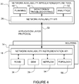
- FIG. 4 is a block diagram illustrating an example of network availability instrumentation API 18 installed at the routers 14 in communication with network availability API 26 at offline tool 20.
- the NA API 18 may be installed at any number of routers 14 in the network.
- each NA API 18 at the routers 14 may be in communication with any number of NA APIs 26.
- Any number of applications at the offline tool 20 may interact with any number of NA APIs 18 at the routers 14, thus enabling the applications to communicate with one or more routers for the purpose of requesting and receiving network availability information.
- the NA API 18 may be used with third party applications that offer a standardized API, which allows other applications to register their interest for the availability state of some customer ports (e.g., all demands originating from a specified port of a specific edge router) or specified destinations or services. Through use of the NA API, applications are informed of the availability of the network service and can therefore take any necessary measure to improve the availability. Actions may include, for example, switching service provider or using other data centers to host a portion of their services. Service requests are met based on computation of network availability analytics described herein.
- the uniform programming interface facilitates the development and implementation of multiple applications that can take advantage of accurate network availability information.
- planning application 48 can periodically compute network wide availability and use that as one factor when engineering the optimal use of network resources or improved services.
- Monitoring and troubleshooting application 50 may use the network availability information to examine network availability (in near real-time or in playback mode) to pinpoint the root cause of a problem.
- Analytics application 52 may process multiple information feeds such as routing protocols, SNMP, NetFlow, and network availability data, and use the information to present a precise picture of the network health at different timescales. This rolled up view of network health aids the operator in managing the network and can be used to monetize its value.
- the network availability API 18 on the router 14 interacts with the one or more subsystems (e.g., RCMD module 38, DDM module 39, NetFlow data 54, topology data 56) configured to generate and collect network data. It is to be understood that these are only examples of data that may be monitored or collected and that other data (e.g., packet drops) may be used to provide an indication of network availability.
- An application layer protocol may be used to transport network availability information over link/path 58 as shown in Figure 4 .
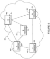
- Figure 5 illustrates an example of routers 60 comprising RCMD (Route Convergence Monitoring and Diagnostics) and DDM (Distributed Demand Matrix) components 64 for use in providing route convergence and traffic demand measurements.
- the example shown in Figure 5 includes edge routers A, B, C, D, and core router E.
- the DDM/RCMD components 64 may include, for example, RCMD module 38, DDM module 39, or both RCMD and DDM modules.
- RCMD is implemented at routers 60 in network 65 to measure the convergence behavior of various routing protocols and extensions (e.g., ISIS (Intermediate System-to-Intermediate System), OSPF (Open Shortest Path First), BGP (Border Gateway Protocol), TE (Traffic Engineering), LDP (Label Distribution Protocol), LFA (Loop Free Alternate), PIM (Protocol Independent Multicast), mLDP (multicast Label Distribution Protocol)).
- ISIS Intermediate System-to-Intermediate System
- OSPF Open Shortest Path First
- BGP Border Gateway Protocol
- TE Traffic Engineering
- LDP Label Distribution Protocol
- LFA Loop Free Alternate
- PIM Protocol Independent Multicast
- mLDP multicast Label Distribution Protocol
- RCMD can operate in a monitoring mode for detecting events and measuring convergence, and a diagnostics mode for additional debug information collection for abnormal events.
- RCMD identifies all of the reasons (i.e., triggers) that lead to a given routing table recomputation (route computation). This identification scheme allows for correlation across all route convergence measurements.
- RCMD operates as described in U.S. Patent Application Publication Number US 20130265881 A1 filed February 4, 2013 , entitled "Route Convergence Monitoring and Diagnostics".
- RCMD may be used to measure the time it takes from a change in the network to the time for a router to adjust its hardware to the change (T2-T0).
- the embodiments may also be used to measure the time it takes for any router receiving the change information to make a change in its hardware such that the information is now used to forward packets (T2-T1).
- the time period (T2-T1) is significant in that many components are involved in operations at the router that lead to the change in hardware.
- a flooding measurement identifies the time between when the failure message originated at the detecting router and when it is received at the rerouting router (T1-T0).
- a timestamp is used for marking time T0 when a change occurs (e.g., link down).
- the routers transmit route information (e.g., a link state packet (LSP) in ISIS or a link state announcement (LSA) in OSPF).
- LSP link state packet
- LSA link state announcement
- the router adds the timestamp indicating the time (T0) that it originated the new route information.
- the rerouting router receives the information at T1 and updates its routing information.
- An update measurement identifies the time between when the failure notification is received at the rerouting router (T1) and when a last important prefix is installed across all of its linecards (T2).
- convergence time (T2-T1) at the router 14 is measured using markers.
- the markers are flags attached to internal routing information associated with topology information received from the network.
- the markers are tracked as the internal routing information propagates from one routing component to the next within software at the router.
- any component receives a marker it saves a timestamp associated with that particular marker.
- the final component that modifies the hardware saves the timestamp, which is time T2.
- only select routes are tracked. Routes may be selected based on a policy such as priority levels. The routing components thus act on a limited number of markers rather than each route that is processed. This greatly reduces the work required to track the routes through the routing components and the amount of tracking data that needs to be stored.
- a measurement component in the system collects tracking information on the router and by comparing the saved timestamps (T0 and T2) it can find the end-to-end convergence. Problems local to the router may be identified by examining the time interval from T1 through T2.
- RCMD may be used for ISIS and OSPF convergence measurement and to gather details about SPF (Shortest Path First) runs and time taken to provision routes and LDP (Label Distribution Protocol) labels across all linecards on the router. RCMD may also be used to provide information about LFA (Loop Free Alternate) coverage available at the end of each SPF run, and BGP (Border Gateway Protocol) and TE (Traffic Engineering) information. Since RCMD is used to monitor various routing convergence events, implementation is embedded within routing subsystem components, including for example, ISIS, OSPF, RIB (Routing Information Base), LDP, LSD (Label Switching Database), and FIB (Forwarding Information Base).
- ISIS ISIS
- OSPF RIB (Routing Information Base)
- LDP Label Switching Database
- FIB Forwarding Information Base
- the traffic demand measurements comprise the router's share of a demand matrix as described in U.S. Patent Application Publication Number US 20130265905 A1, filed January 29, 2013 , entitled "Distributed Demand Matrix Computations".
- a demand represents traffic flowing between any two edge devices in the network. There may be any number of traffic flows across the network.
- a demand matrix (traffic matrix, traffic demand matrix) describes the aggregation of flows at the edge of the network.
- a demand is a single element (cell) of the demand matrix associated with a source and destination in the network. Each demand is thus a single entry in the demand matrix that identifies the amount of traffic that enters the network at one point and leaves the network at another point.
- traffic may enter a network at router A and traverse the network along a path until it reaches router B, where it leaves the network.
- information is collected about all of the traffic and how it enters and exits the network. Traffic measurements are mapped to individual demands.
- a demand matrix for four interconnected edge devices A, B, C, D as shown in Figure 5 may be expressed as follows:
- Each row of the above demand matrix includes cells corresponding to traffic received at one of the edge devices.
- the first row comprises cells corresponding to traffic received at router A that will egress the network at router A (AA), router B (AB), router C (AC), and router D (AD).
- the second row comprises cells corresponding to traffic received at router B that will egress the network at router A (BA), router B (BB), router C (BC), and router D (BD)
- the third and fourth rows comprise the cells corresponding to traffic entering the network at routers C and D, respectively.
- Each router computes its own row (local demands) for the demand matrix.
- the local demands (portions of the demand matrix) from each of the routers can be collected at one or more of the routers, or another device (e.g., offline tool 20) and the complete demand matrix generated.
- One or more routers in the network may include DDM module 39 configured to compute all of the [X, Y] cells of the demand matrix, where X is the router at which the DDM module is located.
- the router further includes a demand database maintained by the DDM module. DDM measurements from each linecard are stored in the database for a specified time period. The demands in the database may be retrieved for use by capacity planning applications or other operational applications running on the offline tool 20. Demands from the database may also be advertised to other routers participating in the DDM process.
- Each DDM module 39 is also configured for synchronized periodic measurement archive.
- each database comprises a plurality of demands computed and stored for a time period. All of the time periods used at each edge device have a common multiple. This timing rule makes it possible to combine the distributed measurements of different routers and ensure that it is straightforward to recompose the different cells into matrices that relate to a specific time period.
- RCMD and DDM measurements described above are only examples of route convergence measurements and traffic demand measurements that may be used to compute network availability as described herein.
Landscapes
- Engineering & Computer Science (AREA)
- Computer Networks & Wireless Communication (AREA)
- Signal Processing (AREA)
- Environmental & Geological Engineering (AREA)
- Data Mining & Analysis (AREA)
- Data Exchanges In Wide-Area Networks (AREA)
Claims (15)
- Verfahren, umfassend:Empfangen von Routenkonvergenzmessungen und Verkehrsbedarfsmessungen von einer Vielzahl von Routern (10, 12, 14) an einer Netzwerkvorrichtung (21); wobei die Routenkonvergenzmessungen Netzwerkkonvergenzereignisse betreffen und mit Routenberechnungen an den Routern assoziiert sind und wobei die Verkehrsbedarfsmessungen Bedarfe einer Bedarfsmatrix umfassen, die mit den Routern assoziiert ist, wobei ein Bedarf eine Zelle der Bedarfsmatrix ist, die eine Verkehrsmenge spezifiziert, die zwischen zwei Edge-Vorrichtungen des Netzwerks (10, 12) fließt, und die Bedarfsmatrix die Aggregation von Flüssen an der Edge des Netzwerks beschreibt; undBerechnen einer Netzwerkverfügbarkeit an der Netzwerkvorrichtung auf der Basis der Routenkonvergenzmessungen und der Verkehrsbedarfsmessungen, wobei das Berechnen der Netzwerkverfügbarkeit für einen gegebenen Zeitraum Folgendes umfasst:Bestimmen einer Verkehrsmenge, die aufgrund von Netzwerkkonvergenzereignissen während des Zeitraums verloren geht;Bestimmen einer Verkehrsmenge, die über den gegebenen Zeitraum in das Netzwerk eingeht; undBerechnen der Netzwerkverfügbarkeit auf der Basis der verloren gegangenen Verkehrsmenge und der in das Netzwerk eingehenden Verkehrsmenge.
- Verfahren nach Anspruch 1, umfassend ein Berechnen der verloren gegangenen Verkehrsmenge als die Summe von verloren gegangenem Verkehr über alle Bedarfe der Bedarfsmatrix, der während des Ereignisses gesammelt wurde.
- Verfahren nach Anspruch 2, umfassend ein Berechnen des verloen gegangenen Verkehrs für jeden Bedarf auf der Basis eines Produkts des Bedarfs und einer Konvergenzzeit für das Ziel des Bedarfs.
- Verfahren nach Anspruch 1, wobei das Empfangen der Routenkonvergenz- und der Verkehrsbedarfsmessungen ein Empfangen der Messungen an einer Anwendungsprogrammierschnittstelle (26) umfasst.
- Verfahren nach Anspruch 4, wobei die Messungen für eine spezifische Stelle in dem Netzwerk empfangen werden.
- Verfahren nach Anspruch 4, wobei die Messungen für einen spezifizierten Dienst empfangen werden.
- Verfahren nach Anspruch 1, wobei das Berechnen der Netzwerkverfügbarkeit ein Berechnen einer Ende-zu-Ende-Konvergenz für einen Fluss von einem Ausgangspunkt (10) zu einem Ziel (12) umfasst.
- Verfahren nach Anspruch 1, wobei die Netzwerkverfügbarkeit an einer Planungsanwendung (48) berechnet wird.
- Verfahren nach Anspruch 1, wobei die Netzwerkverfügbarkeit von einer Überwachungs- und Fehlerbehebungsanwendung (50) verwendet wird.
- Verfahren nach Anspruch 1, wobei die Netzwerkverfügbarkeit an einer Analytikanwendung (52) berechnet wird, die dazu betreibbar ist, die Netzwerkverfügbarkeit und Netzwerkflussdaten zu verarbeiten.
- Verfahren nach Anspruch 1, wobei die Teile der Bedarfsmatrix, die mit den Routern assoziiert ist, an den Routern berechnet werden.
- Vorrichtung (21), umfassend:Mittel zum Empfangen von Routenkonvergenzmessungen und Verkehrsbedarfsmessungen von einer Vielzahl von Routern (10, 12, 14); wobei die Routenkonvergenzmessungen Netzwerkkonvergenzereignisse betreffen und mit Routenberechnungen an den Routern assoziiert sind und wobei die Verkehrsbedarfsmessungen Bedarfe einer Bedarfsmatrix umfassen, die mit den Routern assoziiert ist, wobei ein Bedarf eine Zelle der Bedarfsmatrix ist, die eine Verkehrsmenge spezifiziert, die zwischen zwei Edge-Vorrichtungen des Netzwerks (10, 12) fließt, und die Bedarfsmatrix die Aggregation von Flüssen an der Edge des Netzwerks beschreibt; undMittel zum Berechnen einer Netzwerkverfügbarkeit auf der Basis der Routenkonvergenzmessungen und der Verkehrsbedarfsmessungen; wobei das Berechnungsmittel zu Folgendem konfiguriert ist:Bestimmen einer Verkehrsmenge, die aufgrund von Netzwerkkonvergenzereignissen während eines gegebenen Zeitraums verloren geht;Bestimmen einer Verkehrsmenge, die über den gegebenen Zeitraum in das Netzwerk eingeht; undBerechnen der Netzwerkverfügbarkeit auf der Basis der verloren gegangenen Verkehrsmenge und der in das Netzwerk eingehenden Verkehrsmenge.
- Vorrichtung nach Anspruch 12, die dazu eingerichtet ist, ein Verfahren nach einem der Ansprüche 2 bis 11 durchzuführen.
- Computerprogrammprodukt, umfassend Anweisungen, die auf einem oder mehreren greifbaren computerlesbaren Medien zur Ausführung codiert sind und bei Ausführung an einer Netzwerkvorrichtung (21) zu Folgendem betreibbar sind:Empfangen von Routenkonvergenzmessungen und Verkehrsbedarfsmessungen von einer Vielzahl von Routern (10, 12, 14) an der Netzwerkvorrichtung; wobei die Routenkonvergenzmessungen Netzwerkkonvergenzereignisse betreffen und mit Routenberechnungen an den Routern assoziiert sind und wobei die Verkehrsbedarfsmessungen Bedarfe einer Bedarfsmatrix umfassen, die mit den Routern assoziiert ist, wobei ein Bedarf eine Zelle der Bedarfsmatrix ist, die eine Verkehrsmenge spezifiziert, die zwischen zwei Edge-Vorrichtungen des Netzwerks (10, 12) fließt, und die Bedarfsmatrix die Aggregation von Flüssen an der Edge des Netzwerks beschreibt; undBerechnen einer Netzwerkverfügbarkeit auf der Basis der Routenkonvergenzmessungen und der Verkehrsbedarfsmessungen, wobei das Berechnen der Netzwerkverfügbarkeit für einen gegebenen Zeitraum Folgendes umfasst:Bestimmen einer Verkehrsmenge, die aufgrund von Netzwerkkonvergenzereignissen während des Zeitraums verloren geht;Bestimmen einer Verkehrsmenge, die über den gegebenen Zeitraum in das Netzwerk eingeht; undBerechnen der Netzwerkverfügbarkeit auf der Basis der verloren gegangenen Verkehrsmenge und der in das Netzwerk eingehenden Verkehrsmenge.
- Computerprogrammprodukt, umfassend Anweisungen, nach Anspruch 14, weiterhin umfassend zusätzliche Anweisungen zum Durchführen eines Verfahrens nach einem der Ansprüche 2 bis 11.
Applications Claiming Priority (3)
| Application Number | Priority Date | Filing Date | Title |
|---|---|---|---|
| US201261621811P | 2012-04-09 | 2012-04-09 | |
| US13/780,253 US9479403B2 (en) | 2012-04-09 | 2013-02-28 | Network availability analytics |
| PCT/US2013/035689 WO2013155023A1 (en) | 2012-04-09 | 2013-04-09 | Network availability analytics |
Publications (2)
| Publication Number | Publication Date |
|---|---|
| EP2837136A1 EP2837136A1 (de) | 2015-02-18 |
| EP2837136B1 true EP2837136B1 (de) | 2019-12-18 |
Family
ID=49292230
Family Applications (2)
| Application Number | Title | Priority Date | Filing Date |
|---|---|---|---|
| EP13770722.0A Active EP2837137B1 (de) | 2012-04-09 | 2013-04-08 | Verteilte berechnungen für anfragenmatrix |
| EP13717403.3A Active EP2837136B1 (de) | 2012-04-09 | 2013-04-09 | Analytik von netzwerkverfügbarkeit |
Family Applications Before (1)
| Application Number | Title | Priority Date | Filing Date |
|---|---|---|---|
| EP13770722.0A Active EP2837137B1 (de) | 2012-04-09 | 2013-04-08 | Verteilte berechnungen für anfragenmatrix |
Country Status (4)
| Country | Link |
|---|---|
| US (3) | US9106510B2 (de) |
| EP (2) | EP2837137B1 (de) |
| CN (2) | CN104221328B (de) |
| WO (2) | WO2013155021A2 (de) |
Families Citing this family (51)
| Publication number | Priority date | Publication date | Assignee | Title |
|---|---|---|---|---|
| US8549176B2 (en) * | 2004-12-01 | 2013-10-01 | Cisco Technology, Inc. | Propagation of routing information in RSVP-TE for inter-domain TE-LSPs |
| US9137101B2 (en) * | 2011-11-23 | 2015-09-15 | Avaya Inc. | Multi-layer network diagnostic tracing |
| US20140044129A1 (en) * | 2012-08-10 | 2014-02-13 | Duane Edward MENTZE | Multicast packet forwarding in a network |
| US10374938B1 (en) | 2012-12-27 | 2019-08-06 | Sitting Man, Llc | Routing methods, systems, and computer program products |
| US10397101B1 (en) | 2012-12-27 | 2019-08-27 | Sitting Man, Llc | Routing methods, systems, and computer program products for mapping identifiers |
| US10404582B1 (en) | 2012-12-27 | 2019-09-03 | Sitting Man, Llc | Routing methods, systems, and computer program products using an outside-scope indentifier |
| US10419335B1 (en) | 2012-12-27 | 2019-09-17 | Sitting Man, Llc | Region scope-specific outside-scope indentifier-equipped routing methods, systems, and computer program products |
| US10411997B1 (en) | 2012-12-27 | 2019-09-10 | Sitting Man, Llc | Routing methods, systems, and computer program products for using a region scoped node identifier |
| US10212076B1 (en) | 2012-12-27 | 2019-02-19 | Sitting Man, Llc | Routing methods, systems, and computer program products for mapping a node-scope specific identifier |
| US10587505B1 (en) | 2012-12-27 | 2020-03-10 | Sitting Man, Llc | Routing methods, systems, and computer program products |
| US10397100B1 (en) | 2012-12-27 | 2019-08-27 | Sitting Man, Llc | Routing methods, systems, and computer program products using a region scoped outside-scope identifier |
| US10447575B1 (en) | 2012-12-27 | 2019-10-15 | Sitting Man, Llc | Routing methods, systems, and computer program products |
| US10411998B1 (en) | 2012-12-27 | 2019-09-10 | Sitting Man, Llc | Node scope-specific outside-scope identifier-equipped routing methods, systems, and computer program products |
| US10419334B1 (en) | 2012-12-27 | 2019-09-17 | Sitting Man, Llc | Internet protocol routing methods, systems, and computer program products |
| US10476787B1 (en) | 2012-12-27 | 2019-11-12 | Sitting Man, Llc | Routing methods, systems, and computer program products |
| US10404583B1 (en) | 2012-12-27 | 2019-09-03 | Sitting Man, Llc | Routing methods, systems, and computer program products using multiple outside-scope identifiers |
| US10904144B2 (en) | 2012-12-27 | 2021-01-26 | Sitting Man, Llc | Methods, systems, and computer program products for associating a name with a network path |
| US10084650B2 (en) * | 2013-07-09 | 2018-09-25 | Tail-f Systems AB | Graphical user interface for customizing graphical representations based on registry data |
| US9686581B2 (en) | 2013-11-07 | 2017-06-20 | Cisco Technology, Inc. | Second-screen TV bridge |
| US20150281050A1 (en) * | 2014-03-31 | 2015-10-01 | Alcatel-Lucent Usa Inc. | Method for Adjacency Status Synchronization in Label Distribution Protocol |
| US10222935B2 (en) | 2014-04-23 | 2019-03-05 | Cisco Technology Inc. | Treemap-type user interface |
| US10448246B2 (en) | 2014-04-29 | 2019-10-15 | Hewlett Packard Enterprise Development Lp | Network re-convergence point |
| CN105024927A (zh) * | 2014-04-30 | 2015-11-04 | 中国电信股份有限公司 | 一种计算路由收敛能力的方法和系统 |
| WO2016014086A1 (en) * | 2014-07-25 | 2016-01-28 | Hewlett-Packard Development Company, L.P. | Software-defined sensing |
| US9529531B2 (en) | 2014-10-06 | 2016-12-27 | Barefoot Networks, Inc. | Proxy hash table |
| JP6299640B2 (ja) * | 2015-03-23 | 2018-03-28 | 横河電機株式会社 | 通信装置 |
| US9985875B1 (en) | 2015-03-31 | 2018-05-29 | Juniper Networks, Inc. | Route signalling based resilient application overlay network |
| US10250562B1 (en) * | 2015-03-31 | 2019-04-02 | Juniper Networks, Inc. | Route signaling driven service management |
| US10397092B2 (en) | 2015-04-30 | 2019-08-27 | Hewlett Packard Enterprise Development Lp | Reducing flooding of route updates of a dynamic routing protocol |
| US9729427B2 (en) * | 2015-05-08 | 2017-08-08 | Arista Networks, Inc. | Method and system for route hardware programming in network devices |
| US9491282B1 (en) * | 2015-05-13 | 2016-11-08 | Cisco Technology, Inc. | End-to-end call tracing |
| CN111277494B (zh) | 2016-02-16 | 2021-08-13 | 华为技术有限公司 | 一种报文传输方法及装置 |
| US10063457B2 (en) * | 2016-03-29 | 2018-08-28 | Juniper Networks, Inc. | Method, system, and apparatus for improving forwarding capabilities during route convergence |
| US11025485B2 (en) | 2016-09-15 | 2021-06-01 | At&T Intellectual Property I, L.P. | Telecommunication network analytics platform |
| CN106506258A (zh) * | 2016-10-12 | 2017-03-15 | 重庆金美通信有限责任公司 | 一种通信网络分布式路由协议收敛时间测试的方法、系统和设备 |
| CN106549825A (zh) * | 2016-10-13 | 2017-03-29 | 重庆金美通信有限责任公司 | 一种通信网络路由转发表正确性测试的方法、系统和设备 |
| US10372520B2 (en) | 2016-11-22 | 2019-08-06 | Cisco Technology, Inc. | Graphical user interface for visualizing a plurality of issues with an infrastructure |
| US10739943B2 (en) | 2016-12-13 | 2020-08-11 | Cisco Technology, Inc. | Ordered list user interface |
| US10158573B1 (en) * | 2017-05-01 | 2018-12-18 | Barefoot Networks, Inc. | Forwarding element with a data plane load balancer |
| US20180365571A1 (en) * | 2017-06-14 | 2018-12-20 | Microsoft Technology Licensing, Llc | Dynamic Converging Times for Real-Time Data Monitoring |
| US10608913B2 (en) * | 2017-06-23 | 2020-03-31 | Keysight Technologies Singapore (Sales) Pte. Ltd. | Methods, systems, and computer readable media for conducting and validating network route convergence testing |
| US10636423B2 (en) * | 2018-02-21 | 2020-04-28 | Motorola Solutions, Inc. | System and method for managing speech recognition |
| US10862867B2 (en) | 2018-04-01 | 2020-12-08 | Cisco Technology, Inc. | Intelligent graphical user interface |
| CN112995750B (zh) * | 2019-12-17 | 2024-04-30 | 天翼数字生活科技有限公司 | 家庭路由器场景下实现iptv组播服务的方法及系统 |
| FR3106027A1 (fr) * | 2020-01-06 | 2021-07-09 | Orange | Procédé de gestion du routage de données dans un système de communication et dispositifs pour la mise en œuvre du procédé |
| US11290941B2 (en) * | 2020-02-28 | 2022-03-29 | At&T Intellectual Property I, L.P. | Selectively using a co-processor to process network routing information in a fifth generation (5G) or other next generation network |
| US11617107B2 (en) | 2021-06-03 | 2023-03-28 | Nile Global, Inc. | Methods and systems for service-level agreement (SLA) network coverage management |
| WO2022256264A1 (en) * | 2021-06-03 | 2022-12-08 | Nile Global, Inc. | Methods and systems for service-level agreement (sla) network availability, network coverage, network capacity management |
| CN114039859B (zh) * | 2021-11-03 | 2023-05-30 | 中盈优创资讯科技有限公司 | 一种stn网络设备链改环方法及装置 |
| US12001856B2 (en) * | 2022-06-14 | 2024-06-04 | Cisco Technology, Inc. | Configuration validation in a disaggregated network OS environment |
| CN116094942B (zh) * | 2023-04-06 | 2023-10-27 | 北京航天万源科技有限公司 | 分布式智能设备协同工作的方法、装置、电子设备及存储介质 |
Family Cites Families (24)
| Publication number | Priority date | Publication date | Assignee | Title |
|---|---|---|---|---|
| JP3063721B2 (ja) * | 1997-04-30 | 2000-07-12 | 日本電気株式会社 | トポロジー情報交換装置及びプログラムを記録した機械読み取り可能な記録媒体 |
| US6857026B1 (en) * | 1999-12-14 | 2005-02-15 | Nortel Networks Limited | Using alternate routes for fail-over in a communication network |
| DE10107433A1 (de) * | 2001-02-16 | 2002-08-29 | Infineon Technologies Ag | Schaltungsanordnung zur Datenstromverteilung mit Konfliktauflösung |
| US7002960B1 (en) | 2001-10-30 | 2006-02-21 | At&T Corp. | Traffic matrix computation for packet networks |
| US7743139B1 (en) | 2001-10-30 | 2010-06-22 | At&T Intellectual Property Ii, L.P. | Method of provisioning a packet network for handling incoming traffic demands |
| US7027396B1 (en) * | 2002-02-13 | 2006-04-11 | At&T Corp. | Traffic matrix computation for a backbone network supporting virtual private networks |
| GB0220660D0 (en) * | 2002-09-05 | 2002-10-16 | Nokia Corp | Signal propogation delay routing |
| GB2399708B (en) * | 2003-03-20 | 2006-03-22 | Parc Technologies Ltd | Assisted determination of data flows in communication/data networks |
| US7646706B2 (en) * | 2003-03-31 | 2010-01-12 | Alcatel-Lucent Usa Inc. | Restoration time in mesh networks |
| US7436838B2 (en) * | 2004-12-29 | 2008-10-14 | Cisco Technology, Inc. | Automatic prioritization of BGP next-hop in IGP |
| US7433320B2 (en) * | 2005-02-01 | 2008-10-07 | Cisco Technology, Inc. | System and methods for network path detection |
| US7532631B2 (en) * | 2005-04-13 | 2009-05-12 | Cisco Technology, Inc. | Method and apparatus for accelerating border gateway protocol convergence |
| WO2006130840A2 (en) | 2005-06-02 | 2006-12-07 | Georgia Tech Research Corporation | System and method for data streaming |
| US7627290B2 (en) * | 2005-07-07 | 2009-12-01 | Cisco Technology, Inc. | Route convergence monitoring system and method |
| JP2007104536A (ja) * | 2005-10-07 | 2007-04-19 | Sony Corp | 無線端末及びプログラム |
| US7904586B1 (en) * | 2005-12-29 | 2011-03-08 | At&T Intellectual Property Ii, L.P. | Traffic engineering method with tunable inter-domain egress selection |
| US7817549B1 (en) * | 2006-06-30 | 2010-10-19 | Extreme Networks, Inc. | Flexible flow-aging mechanism |
| US7831700B2 (en) * | 2006-10-16 | 2010-11-09 | Futurewei Technologies, Inc. | Distributed PCE-based system and architecture in multi-layer network |
| US20080165685A1 (en) * | 2007-01-09 | 2008-07-10 | Walter Weiss | Methods, systems, and computer program products for managing network bandwidth capacity |
| US7898973B2 (en) | 2007-05-30 | 2011-03-01 | Cisco Technology, Inc. | Convergence measurement in computer network |
| US8427970B2 (en) * | 2008-11-14 | 2013-04-23 | Laris Benkis | Apparatus and method for determining a service interruption time measurement |
| US7796514B2 (en) * | 2008-12-11 | 2010-09-14 | At&T Intellectual Property I, L.P. | System and method for multi-services packet network traffic engineering |
| CN101848160B (zh) * | 2010-05-26 | 2012-07-18 | 钱叶魁 | 在线检测和分类全网络流量异常的方法 |
| CN102143042B (zh) * | 2010-07-09 | 2014-04-16 | 华为技术有限公司 | 虚拟集群路由器系统及其流量分担方法、控制器和子路由器 |
-
2013
- 2013-01-29 US US13/752,926 patent/US9106510B2/en active Active
- 2013-02-04 US US13/758,501 patent/US9237075B2/en active Active
- 2013-02-28 US US13/780,253 patent/US9479403B2/en active Active
- 2013-04-08 EP EP13770722.0A patent/EP2837137B1/de active Active
- 2013-04-08 WO PCT/US2013/035687 patent/WO2013155021A2/en not_active Ceased
- 2013-04-08 CN CN201380018940.7A patent/CN104221328B/zh active Active
- 2013-04-09 WO PCT/US2013/035689 patent/WO2013155023A1/en not_active Ceased
- 2013-04-09 EP EP13717403.3A patent/EP2837136B1/de active Active
- 2013-04-09 CN CN201380018852.7A patent/CN104221327B/zh active Active
Non-Patent Citations (1)
| Title |
|---|
| None * |
Also Published As
| Publication number | Publication date |
|---|---|
| EP2837136A1 (de) | 2015-02-18 |
| CN104221328A (zh) | 2014-12-17 |
| US9237075B2 (en) | 2016-01-12 |
| WO2013155023A1 (en) | 2013-10-17 |
| WO2013155021A3 (en) | 2014-01-03 |
| US9479403B2 (en) | 2016-10-25 |
| EP2837137B1 (de) | 2019-07-24 |
| US20130265905A1 (en) | 2013-10-10 |
| US9106510B2 (en) | 2015-08-11 |
| EP2837137A2 (de) | 2015-02-18 |
| US20130265894A1 (en) | 2013-10-10 |
| CN104221327B (zh) | 2019-05-10 |
| US20130265881A1 (en) | 2013-10-10 |
| CN104221327A (zh) | 2014-12-17 |
| CN104221328B (zh) | 2017-11-17 |
| WO2013155021A2 (en) | 2013-10-17 |
Similar Documents
| Publication | Publication Date | Title |
|---|---|---|
| EP2837136B1 (de) | Analytik von netzwerkverfügbarkeit | |
| US11405295B2 (en) | Scalable distributed end-to-end performance delay measurement for segment routing policies | |
| US8036121B2 (en) | Method of estimating quality degradation on network in communication network system | |
| CN107005437B (zh) | 网络断层扫描的方法和装置 | |
| EP2843875A1 (de) | Bestimmung und Verwendung von Verbindungsleistungsmaßen | |
| US20160308709A1 (en) | Method and system for restoring qos degradations in mpls networks | |
| WO2012041251A1 (zh) | 一种路由控制方法、系统及路由计算装置 | |
| US20250150930A1 (en) | Wireless signal strength-based detection of poor network link performance | |
| CN102546248B (zh) | 多协议标签交换环境下精确定位故障位置的方法、装置及系统 | |
| CN107888490B (zh) | 一种报文转发方法、路由时延计算与调度装置及系统 | |
| US8631115B2 (en) | Connectivity outage detection: network/IP SLA probes reporting business impact information | |
| US20190158368A1 (en) | Traffic monitoring in a packet-switched communication network | |
| EP3718261B1 (de) | System zur netzwerkereignisdetektion und -analyse | |
| US7969908B2 (en) | Connectivity outage detection based on a multicast management MPLS-VPN group | |
| Kim et al. | Protection switching methods for point‐to‐multipoint connections in packet transport networks | |
| Karakus et al. | Economic analysis of software defined networking (SDN) under various network failure scenarios | |
| Zhao et al. | SRmesh: Deterministic and efficient diagnosis of latency bottleneck links in SRv6 networks | |
| JP5117534B2 (ja) | ネットワーク監視装置、ネットワーク監視方法及びネットワーク監視プログラム | |
| Vidalenc et al. | GMPLS adaptive level of recovery | |
| Saxena et al. | On the inadequacy of link connectivity monitoring | |
| Ohara | Routing Architecture for the Dependable Internet | |
| Hei et al. | IP network failure identification based on the detailed analysis of OSPF LSA flooding | |
| Mao | Effective diagnosis of routing disruptions from end systems | |
| Tachibana et al. | IP performance management infrastructure for ISP |
Legal Events
| Date | Code | Title | Description |
|---|---|---|---|
| PUAI | Public reference made under article 153(3) epc to a published international application that has entered the european phase |
Free format text: ORIGINAL CODE: 0009012 |
|
| 17P | Request for examination filed |
Effective date: 20140930 |
|
| AK | Designated contracting states |
Kind code of ref document: A1 Designated state(s): AL AT BE BG CH CY CZ DE DK EE ES FI FR GB GR HR HU IE IS IT LI LT LU LV MC MK MT NL NO PL PT RO RS SE SI SK SM TR |
|
| AX | Request for extension of the european patent |
Extension state: BA ME |
|
| DAX | Request for extension of the european patent (deleted) | ||
| STAA | Information on the status of an ep patent application or granted ep patent |
Free format text: STATUS: EXAMINATION IS IN PROGRESS |
|
| 17Q | First examination report despatched |
Effective date: 20180509 |
|
| GRAP | Despatch of communication of intention to grant a patent |
Free format text: ORIGINAL CODE: EPIDOSNIGR1 |
|
| STAA | Information on the status of an ep patent application or granted ep patent |
Free format text: STATUS: GRANT OF PATENT IS INTENDED |
|
| INTG | Intention to grant announced |
Effective date: 20190219 |
|
| GRAJ | Information related to disapproval of communication of intention to grant by the applicant or resumption of examination proceedings by the epo deleted |
Free format text: ORIGINAL CODE: EPIDOSDIGR1 |
|
| STAA | Information on the status of an ep patent application or granted ep patent |
Free format text: STATUS: EXAMINATION IS IN PROGRESS |
|
| GRAP | Despatch of communication of intention to grant a patent |
Free format text: ORIGINAL CODE: EPIDOSNIGR1 |
|
| STAA | Information on the status of an ep patent application or granted ep patent |
Free format text: STATUS: GRANT OF PATENT IS INTENDED |
|
| INTC | Intention to grant announced (deleted) | ||
| INTG | Intention to grant announced |
Effective date: 20190719 |
|
| GRAS | Grant fee paid |
Free format text: ORIGINAL CODE: EPIDOSNIGR3 |
|
| GRAA | (expected) grant |
Free format text: ORIGINAL CODE: 0009210 |
|
| STAA | Information on the status of an ep patent application or granted ep patent |
Free format text: STATUS: THE PATENT HAS BEEN GRANTED |
|
| AK | Designated contracting states |
Kind code of ref document: B1 Designated state(s): AL AT BE BG CH CY CZ DE DK EE ES FI FR GB GR HR HU IE IS IT LI LT LU LV MC MK MT NL NO PL PT RO RS SE SI SK SM TR |
|
| REG | Reference to a national code |
Ref country code: CH Ref legal event code: EP |
|
| REG | Reference to a national code |
Ref country code: DE Ref legal event code: R096 Ref document number: 602013064083 Country of ref document: DE |
|
| REG | Reference to a national code |
Ref country code: IE Ref legal event code: FG4D |
|
| REG | Reference to a national code |
Ref country code: AT Ref legal event code: REF Ref document number: 1215784 Country of ref document: AT Kind code of ref document: T Effective date: 20200115 |
|
| REG | Reference to a national code |
Ref country code: NL Ref legal event code: MP Effective date: 20191218 |
|
| PG25 | Lapsed in a contracting state [announced via postgrant information from national office to epo] |
Ref country code: LT Free format text: LAPSE BECAUSE OF FAILURE TO SUBMIT A TRANSLATION OF THE DESCRIPTION OR TO PAY THE FEE WITHIN THE PRESCRIBED TIME-LIMIT Effective date: 20191218 Ref country code: NO Free format text: LAPSE BECAUSE OF FAILURE TO SUBMIT A TRANSLATION OF THE DESCRIPTION OR TO PAY THE FEE WITHIN THE PRESCRIBED TIME-LIMIT Effective date: 20200318 Ref country code: GR Free format text: LAPSE BECAUSE OF FAILURE TO SUBMIT A TRANSLATION OF THE DESCRIPTION OR TO PAY THE FEE WITHIN THE PRESCRIBED TIME-LIMIT Effective date: 20200319 Ref country code: FI Free format text: LAPSE BECAUSE OF FAILURE TO SUBMIT A TRANSLATION OF THE DESCRIPTION OR TO PAY THE FEE WITHIN THE PRESCRIBED TIME-LIMIT Effective date: 20191218 Ref country code: BG Free format text: LAPSE BECAUSE OF FAILURE TO SUBMIT A TRANSLATION OF THE DESCRIPTION OR TO PAY THE FEE WITHIN THE PRESCRIBED TIME-LIMIT Effective date: 20200318 Ref country code: LV Free format text: LAPSE BECAUSE OF FAILURE TO SUBMIT A TRANSLATION OF THE DESCRIPTION OR TO PAY THE FEE WITHIN THE PRESCRIBED TIME-LIMIT Effective date: 20191218 Ref country code: SE Free format text: LAPSE BECAUSE OF FAILURE TO SUBMIT A TRANSLATION OF THE DESCRIPTION OR TO PAY THE FEE WITHIN THE PRESCRIBED TIME-LIMIT Effective date: 20191218 |
|
| REG | Reference to a national code |
Ref country code: LT Ref legal event code: MG4D |
|
| PG25 | Lapsed in a contracting state [announced via postgrant information from national office to epo] |
Ref country code: RS Free format text: LAPSE BECAUSE OF FAILURE TO SUBMIT A TRANSLATION OF THE DESCRIPTION OR TO PAY THE FEE WITHIN THE PRESCRIBED TIME-LIMIT Effective date: 20191218 Ref country code: HR Free format text: LAPSE BECAUSE OF FAILURE TO SUBMIT A TRANSLATION OF THE DESCRIPTION OR TO PAY THE FEE WITHIN THE PRESCRIBED TIME-LIMIT Effective date: 20191218 |
|
| PG25 | Lapsed in a contracting state [announced via postgrant information from national office to epo] |
Ref country code: AL Free format text: LAPSE BECAUSE OF FAILURE TO SUBMIT A TRANSLATION OF THE DESCRIPTION OR TO PAY THE FEE WITHIN THE PRESCRIBED TIME-LIMIT Effective date: 20191218 |
|
| PG25 | Lapsed in a contracting state [announced via postgrant information from national office to epo] |
Ref country code: EE Free format text: LAPSE BECAUSE OF FAILURE TO SUBMIT A TRANSLATION OF THE DESCRIPTION OR TO PAY THE FEE WITHIN THE PRESCRIBED TIME-LIMIT Effective date: 20191218 Ref country code: PT Free format text: LAPSE BECAUSE OF FAILURE TO SUBMIT A TRANSLATION OF THE DESCRIPTION OR TO PAY THE FEE WITHIN THE PRESCRIBED TIME-LIMIT Effective date: 20200513 Ref country code: CZ Free format text: LAPSE BECAUSE OF FAILURE TO SUBMIT A TRANSLATION OF THE DESCRIPTION OR TO PAY THE FEE WITHIN THE PRESCRIBED TIME-LIMIT Effective date: 20191218 Ref country code: NL Free format text: LAPSE BECAUSE OF FAILURE TO SUBMIT A TRANSLATION OF THE DESCRIPTION OR TO PAY THE FEE WITHIN THE PRESCRIBED TIME-LIMIT Effective date: 20191218 Ref country code: RO Free format text: LAPSE BECAUSE OF FAILURE TO SUBMIT A TRANSLATION OF THE DESCRIPTION OR TO PAY THE FEE WITHIN THE PRESCRIBED TIME-LIMIT Effective date: 20191218 |
|
| PG25 | Lapsed in a contracting state [announced via postgrant information from national office to epo] |
Ref country code: SK Free format text: LAPSE BECAUSE OF FAILURE TO SUBMIT A TRANSLATION OF THE DESCRIPTION OR TO PAY THE FEE WITHIN THE PRESCRIBED TIME-LIMIT Effective date: 20191218 Ref country code: IS Free format text: LAPSE BECAUSE OF FAILURE TO SUBMIT A TRANSLATION OF THE DESCRIPTION OR TO PAY THE FEE WITHIN THE PRESCRIBED TIME-LIMIT Effective date: 20200418 Ref country code: SM Free format text: LAPSE BECAUSE OF FAILURE TO SUBMIT A TRANSLATION OF THE DESCRIPTION OR TO PAY THE FEE WITHIN THE PRESCRIBED TIME-LIMIT Effective date: 20191218 |
|
| REG | Reference to a national code |
Ref country code: DE Ref legal event code: R097 Ref document number: 602013064083 Country of ref document: DE |
|
| REG | Reference to a national code |
Ref country code: AT Ref legal event code: MK05 Ref document number: 1215784 Country of ref document: AT Kind code of ref document: T Effective date: 20191218 |
|
| PLBE | No opposition filed within time limit |
Free format text: ORIGINAL CODE: 0009261 |
|
| STAA | Information on the status of an ep patent application or granted ep patent |
Free format text: STATUS: NO OPPOSITION FILED WITHIN TIME LIMIT |
|
| PG25 | Lapsed in a contracting state [announced via postgrant information from national office to epo] |
Ref country code: ES Free format text: LAPSE BECAUSE OF FAILURE TO SUBMIT A TRANSLATION OF THE DESCRIPTION OR TO PAY THE FEE WITHIN THE PRESCRIBED TIME-LIMIT Effective date: 20191218 Ref country code: DK Free format text: LAPSE BECAUSE OF FAILURE TO SUBMIT A TRANSLATION OF THE DESCRIPTION OR TO PAY THE FEE WITHIN THE PRESCRIBED TIME-LIMIT Effective date: 20191218 |
|
| 26N | No opposition filed |
Effective date: 20200921 |
|
| PG25 | Lapsed in a contracting state [announced via postgrant information from national office to epo] |
Ref country code: SI Free format text: LAPSE BECAUSE OF FAILURE TO SUBMIT A TRANSLATION OF THE DESCRIPTION OR TO PAY THE FEE WITHIN THE PRESCRIBED TIME-LIMIT Effective date: 20191218 Ref country code: AT Free format text: LAPSE BECAUSE OF FAILURE TO SUBMIT A TRANSLATION OF THE DESCRIPTION OR TO PAY THE FEE WITHIN THE PRESCRIBED TIME-LIMIT Effective date: 20191218 Ref country code: MC Free format text: LAPSE BECAUSE OF FAILURE TO SUBMIT A TRANSLATION OF THE DESCRIPTION OR TO PAY THE FEE WITHIN THE PRESCRIBED TIME-LIMIT Effective date: 20191218 |
|
| REG | Reference to a national code |
Ref country code: CH Ref legal event code: PL |
|
| PG25 | Lapsed in a contracting state [announced via postgrant information from national office to epo] |
Ref country code: LI Free format text: LAPSE BECAUSE OF NON-PAYMENT OF DUE FEES Effective date: 20200430 Ref country code: CH Free format text: LAPSE BECAUSE OF NON-PAYMENT OF DUE FEES Effective date: 20200430 Ref country code: LU Free format text: LAPSE BECAUSE OF NON-PAYMENT OF DUE FEES Effective date: 20200409 Ref country code: IT Free format text: LAPSE BECAUSE OF FAILURE TO SUBMIT A TRANSLATION OF THE DESCRIPTION OR TO PAY THE FEE WITHIN THE PRESCRIBED TIME-LIMIT Effective date: 20191218 |
|
| REG | Reference to a national code |
Ref country code: BE Ref legal event code: MM Effective date: 20200430 |
|
| PG25 | Lapsed in a contracting state [announced via postgrant information from national office to epo] |
Ref country code: BE Free format text: LAPSE BECAUSE OF NON-PAYMENT OF DUE FEES Effective date: 20200430 Ref country code: PL Free format text: LAPSE BECAUSE OF FAILURE TO SUBMIT A TRANSLATION OF THE DESCRIPTION OR TO PAY THE FEE WITHIN THE PRESCRIBED TIME-LIMIT Effective date: 20191218 |
|
| PG25 | Lapsed in a contracting state [announced via postgrant information from national office to epo] |
Ref country code: IE Free format text: LAPSE BECAUSE OF NON-PAYMENT OF DUE FEES Effective date: 20200409 |
|
| REG | Reference to a national code |
Ref country code: DE Ref legal event code: R079 Ref document number: 602013064083 Country of ref document: DE Free format text: PREVIOUS MAIN CLASS: H04L0012260000 Ipc: H04L0043000000 |
|
| PG25 | Lapsed in a contracting state [announced via postgrant information from national office to epo] |
Ref country code: TR Free format text: LAPSE BECAUSE OF FAILURE TO SUBMIT A TRANSLATION OF THE DESCRIPTION OR TO PAY THE FEE WITHIN THE PRESCRIBED TIME-LIMIT Effective date: 20191218 Ref country code: MT Free format text: LAPSE BECAUSE OF FAILURE TO SUBMIT A TRANSLATION OF THE DESCRIPTION OR TO PAY THE FEE WITHIN THE PRESCRIBED TIME-LIMIT Effective date: 20191218 Ref country code: CY Free format text: LAPSE BECAUSE OF FAILURE TO SUBMIT A TRANSLATION OF THE DESCRIPTION OR TO PAY THE FEE WITHIN THE PRESCRIBED TIME-LIMIT Effective date: 20191218 |
|
| PG25 | Lapsed in a contracting state [announced via postgrant information from national office to epo] |
Ref country code: MK Free format text: LAPSE BECAUSE OF FAILURE TO SUBMIT A TRANSLATION OF THE DESCRIPTION OR TO PAY THE FEE WITHIN THE PRESCRIBED TIME-LIMIT Effective date: 20191218 |
|
| P01 | Opt-out of the competence of the unified patent court (upc) registered |
Effective date: 20230525 |
|
| PGFP | Annual fee paid to national office [announced via postgrant information from national office to epo] |
Ref country code: DE Payment date: 20250313 Year of fee payment: 13 |
|
| PGFP | Annual fee paid to national office [announced via postgrant information from national office to epo] |
Ref country code: GB Payment date: 20250404 Year of fee payment: 13 |
|
| PGFP | Annual fee paid to national office [announced via postgrant information from national office to epo] |
Ref country code: FR Payment date: 20250402 Year of fee payment: 13 |