EP2837039B1 - Konisches bündelkabelsystem mit verteiltem kombinierer - Google Patents
Konisches bündelkabelsystem mit verteiltem kombinierer Download PDFInfo
- Publication number
- EP2837039B1 EP2837039B1 EP13719639.0A EP13719639A EP2837039B1 EP 2837039 B1 EP2837039 B1 EP 2837039B1 EP 13719639 A EP13719639 A EP 13719639A EP 2837039 B1 EP2837039 B1 EP 2837039B1
- Authority
- EP
- European Patent Office
- Prior art keywords
- conductor
- combiner
- input
- bus
- junction box
- Prior art date
- Legal status (The legal status is an assumption and is not a legal conclusion. Google has not performed a legal analysis and makes no representation as to the accuracy of the status listed.)
- Active
Links
Images




Classifications
-
- H—ELECTRICITY
- H10—SEMICONDUCTOR DEVICES; ELECTRIC SOLID-STATE DEVICES NOT OTHERWISE PROVIDED FOR
- H10F—INORGANIC SEMICONDUCTOR DEVICES SENSITIVE TO INFRARED RADIATION, LIGHT, ELECTROMAGNETIC RADIATION OF SHORTER WAVELENGTH OR CORPUSCULAR RADIATION
- H10F19/00—Integrated devices, or assemblies of multiple devices, comprising at least one photovoltaic cell covered by group H10F10/00, e.g. photovoltaic modules
- H10F19/90—Structures for connecting between photovoltaic cells, e.g. interconnections or insulating spacers
- H10F19/902—Structures for connecting between photovoltaic cells, e.g. interconnections or insulating spacers for series or parallel connection of photovoltaic cells
-
- H—ELECTRICITY
- H10—SEMICONDUCTOR DEVICES; ELECTRIC SOLID-STATE DEVICES NOT OTHERWISE PROVIDED FOR
- H10F—INORGANIC SEMICONDUCTOR DEVICES SENSITIVE TO INFRARED RADIATION, LIGHT, ELECTROMAGNETIC RADIATION OF SHORTER WAVELENGTH OR CORPUSCULAR RADIATION
- H10F19/00—Integrated devices, or assemblies of multiple devices, comprising at least one photovoltaic cell covered by group H10F10/00, e.g. photovoltaic modules
- H10F19/90—Structures for connecting between photovoltaic cells, e.g. interconnections or insulating spacers
-
- H—ELECTRICITY
- H02—GENERATION; CONVERSION OR DISTRIBUTION OF ELECTRIC POWER
- H02S—GENERATION OF ELECTRIC POWER BY CONVERSION OF INFRARED RADIATION, VISIBLE LIGHT OR ULTRAVIOLET LIGHT, e.g. USING PHOTOVOLTAIC [PV] MODULES
- H02S40/00—Components or accessories in combination with PV modules, not provided for in groups H02S10/00 - H02S30/00
- H02S40/30—Electrical components
- H02S40/36—Electrical components characterised by special electrical interconnection means between two or more PV modules, e.g. electrical module-to-module connection
-
- Y—GENERAL TAGGING OF NEW TECHNOLOGICAL DEVELOPMENTS; GENERAL TAGGING OF CROSS-SECTIONAL TECHNOLOGIES SPANNING OVER SEVERAL SECTIONS OF THE IPC; TECHNICAL SUBJECTS COVERED BY FORMER USPC CROSS-REFERENCE ART COLLECTIONS [XRACs] AND DIGESTS
- Y02—TECHNOLOGIES OR APPLICATIONS FOR MITIGATION OR ADAPTATION AGAINST CLIMATE CHANGE
- Y02E—REDUCTION OF GREENHOUSE GAS [GHG] EMISSIONS, RELATED TO ENERGY GENERATION, TRANSMISSION OR DISTRIBUTION
- Y02E10/00—Energy generation through renewable energy sources
- Y02E10/50—Photovoltaic [PV] energy
Definitions
- the invention relates to solar panel systems, and more particularly to trunking system for transporting electrical current from a field of solar panel arrays.
- a solar field typically includes a plurality of rows of solar panel arrays.
- a solar panel can generate 20-50VDC at a current of 6-10A.
- Each solar panel array can have several solar panels joined together to generate a desired voltage (e.g., 600VDC or 1000VDC).
- a desired voltage e.g. 600VDC or 1000VDC.
- 600VDC or 1000VDC e.g. 600VDC or 1000VDC.
- an array with twelve solar panels wired in series, each generating 50VDC at 8.5A can generate a voltage of 600VDC at a current of 8.5A.
- FIG. 8 shows an exploded view of an example prior art row of solar panel arrays 10.
- Row 10 includes a plurality of solar panel arrays, including arrays 12 and 14.
- Each array 12, 14 includes a plurality of solar panels 16, for example two rows of six panels, or twelve panels.
- Each array is coupled directly to a combiner box 20, generally through fuses in the combiner box 20.
- the combiner box 20 can be a great distance from specific arrays. For example, if FIG. 8 , arrays 12 and 14 are shown to be 378 feet and 357 feet away, respectively, from the combiner box 20.
- the conductors used to carry current from the arrays to the combiner box vary in size from wires or cables carried in conduits to thick metal bars (bus bars).
- the cross-sectional area of the conductor (e.g., wire gauge) necessary to carry current from a specific array to the combiner box depends on the amount of current it is to carry and the distance from the array to the combiner box. In FIG. 8 , the combined cross-sectional area of the example conductors is 137 mm 2 .
- Wiring a solar field can require a large amount of resources and labor.
- the conductors carrying current directly from each array to the combiner box is lengthy and thick, requiring a large amount of metal. If row length is approximately 378 feet from the combiner box, each row includes 18 arrays, and the field includes 16 rows of arrays, the field may require on the order of 20 miles of wire. Because the conductors must carry current across a great distance, the total cross-sectional area can be large (e.g., 137 mm 2 in the example of FIG. 8 ). Since wire gauges are sold in standardized sizes, if the precise cross-sectional area is not available, a larger-than-necessary gauge may be required, adding to the materials cost.
- the present disclosure provides a tapered trunking bus for carrying electricity from a row of solar panel arrays to a safety switch.
- the trunking bus includes a number of combiner and junction boxes connected in series.
- the first combiner and junction box combines the electricity from a pair of solar panel arrays and outputs electricity of the desired voltage on a conductor.
- the cross-sectional area of the conductor is chosen to match the current to be carried and to account for the distance to the next combiner and junction box.
- Each successive combiner and junction box combines the output of the previous combiner and junction box with the electrical current received from another pair of solar panel arrays and outputs a higher current at the desired voltage.
- each successive combiner and junction box will be higher than the input current since the current from two more arrays will be added. Accordingly, the gauge or cross-sectional area of the output conductor for each combiner and junction box will be larger than that of the input conductor.
- wires in conduits of increasing gauges, can be used between combiner and junction boxes.
- metal bus bars of increasing cross-sectional area can be used between combiner and junction boxes. Because the conductors between each successive combiner and junction box are progressively larger than the ones before, the trunking bus can be considered tapered.
- each combiner and junction box is short relative to the distance between each array and the safety switch.
- the length of the conductors carrying current from each pair of solar panel arrays to the next pair is shorter (in most cases significantly shorter) than would be necessary to run conductors directly from each solar panel array to a single combiner box for a row of panels. This reduces the lengths of the conductors necessary to carry electricity from the arrays to the safety switch, and as a result, significantly reduces the overall length of conductors. It also reduces the amount of labor required to manually run conductors through conduits.
- the gauge or cross-sectional area of each conductor can be optimized, with large cross-section conductors only used to carry high current. This results in reduced materials cost. For example, conductor material could be reduced by approximately 27 percent. Moreover, power losses can be reduced, for example by approximately nine percent.
- FIG. 1 shows an exploded block diagram of a tapered trunking bus 100 for a row of solar panel arrays 200.
- FIG. 2 shows a perspective view of the tapered trunking bus 100.
- the row of arrays 200 has nine pairs of arrays, including arrays 102, 104, 112, and 114.
- Each array can include several solar panels 106, for example twelve solar panels arranged in series in two rows of six panels.
- FIG. 2 shows arrays 112 and 114 as including panels 106 wired in series.
- Each pair of arrays is electrically connected to a combiner and junction box.
- arrays 102 and 104 are connected to the combiner and junction box 108 and arrays 112 and 114 are connected to the combiner and junction box 110.
- All of the combiner and junction boxes are connected in series.
- the combiner and junction box 108 is connected in series with the combiner and junction box 110, which is connected in series with a combiner and junction box 214.
- the last combiner and junction box 116 in the series is connected to a safety switch 118. For almost every pair of solar panel arrays, the length of the conductors carrying current from each pair of solar panel arrays to the next pair is shorter than the distance between each array and the safety switch 118.
- each combiner and junction box is separated from the next in the series by approximately 42 feet (102).
- Each solar panel 106 generates approximately 50VDC at 8.5A. Therefore, each array generates approximately 600VDC at 8.5A.
- the first combiner and junction box 108 combines the current from the attached arrays 102 and 104 and outputs the combined approximately 17A at 600VDC on conductor 210.
- the next combiner and junction box 110 receives the current carried on conductor 210 and combines that current with the current received from attached arrays 112 and 114 (an additional 17A at 600VDC) and outputs the combined current of 34A at 600VDC on conductor 212.
- Combiner and junction box 214 and the remaining successive combiner and junction boxes each add approximately 17A at 600VDC to the current, for a total of approximately 155A delivered to the safety switch 118.
- conductor 210 is carrying only 17A for a distance of approximately 42 feet, it can be implemented as a wire or cable of appropriate gauge run through a conduit.
- the conductor 212 is configured to carry an additional 17A; thus it can be implemented as a wire or cable of higher gauge than the conductor 210 run through a conduit.
- Conductors configured to carry currents less than approximately 100A can be implemented as wires or cables.
- Conductors expected to carry higher currents (e.g., currents above 100A) can be implemented as rigid metal bus bars, for example bus bars made of copper, aluminum, aluminum with copper deposition, and/or silver flash. As the current progressively increases between combiner and junction boxes, bus bars of progressively larger cross-sectional area can be chosen.
- each combiner and junction box can be connected to subsequent combiner and junction boxes by ground conductors to protect against instances where a grounded combiner and junction box becomes inadvertently energized due to insulation failure or installation error.
- the combiner and junction box 108 can be connected to the combiner and junction box 110 with a ground conductor 216, and the combiner and junction box 110 can be connected to the combiner and junction box 214 by a ground conductor 218.
- the ground conductors 214 and 216 can be connected directly to the housings, for example by screws.
- the conductor 218 can be of a greater cross-sectional area than the conductor 216 (e.g., of a higher gauge). Alternately, the conductors 216 and 218 can have the same cross-sectional area (e.g., the same gauge).
- FIG. 3 shows a perspective view of an embodiment of a combiner and junction box 300.
- the combiner and junction box 300 includes a housing 310, which can be a metal or plastic housing.
- the housing 310 includes a hole 312 for an input conductor 322.
- the input conductor 322 is a cable carried in a conduit 323.
- the housing 310 also includes holes 314, 316 that accept conductors 315, 317 from two solar panel arrays.
- the conductors 315 and 317 are connected to circuit protection devices such as fuses 318, 320 (e.g., 10A fuses). Alternatively, circuit breakers or other circuit protection devices could be used.
- a bus 324 carries current from the two fuses 318, 320 to a combiner and adaptor transition 328 that combines the current from the fuses with the current from the input conductor 322.
- the combiner and adaptor transition 328 can be a connector with three through-holes 326, 330, 334, the through-hole 334 having a larger diameter than the through-hole 330.
- the combiner and adaptor transition 328 is constructed of a conductive material and can include an insulated mounting base 338 for mounting on the housing 310.
- an electrician can strip approximately 1 ⁇ 2 inch of insulator from the input conductor 322 and feed the conductor 322 through the hole 330 in the combiner and adaptor transition 328 such that the uninsulated portion is in the combiner and adaptor transition 328.
- a set screw 336 e.g., an Allen screw
- the conductor 322 can be inserted into the hole 330 with insulation, and the set screw 336 can be a conductive screw (e.g., a brass screw) that is configured to pierce the insulation of the conductor 322 bringing the conductor 322 into conductance with the combiner and adaptor transition 328.
- the bus 324 can be inserted into the hole 326 and joined with the combiner and adaptor transition 328 with a set screw 327 (e.g., an Allen screw or a conductive screw).
- a larger-gauge output conductor 340 (with a portion stripped of insulation or with insulation) can be inserted in the larger through-hole 334 and tightened in place with a set screw 332 (e.g., and Allen screw or a conductive screw).
- the housing 310 includes a hole 342 through which the output conductor 340 exits.
- the output conductor 340 can be a cable carried in a conduit 360.
- the combiner and adaptor transition 328 serves as a junction between the smaller and larger gauge input and output conductors.
- the input and output conductors 322 and 340 can carry positive current.
- the housing 310 can also accept a negative input conductor 352 and a negative output conductor 354 for carrying negative current.
- the negative input conductor 352 can be carried to the housing 310 along with the positive input conductor 322 in the conduit 323 and can enter the housing 310 through the hole 312.
- the negative output conductor 354 can exit the housing 310 through the hole 342 and can be carried from the housing 310 along with the positive output conductor 340 in the conduit 360.
- the negative output conductor 354 can have a higher gauge than the negative input conductor 352.
- the combiner and junction box 300 can also receive conductors 348 and 350 carrying negative current from the pair of solar panel arrays (not shown).
- the negative input conductor 352 can be joined to the conductors 348 and 350 using a combiner and adaptor transition 358 in the same manner as that described above for the positive current, although the negative or ground current need not be fused.
- the combined negative current can be transitioned to the higher-gauge output conductor 354 using the combiner and adaptor transition 358 in the same manner as that described above for the position current.
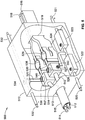
- FIG. 5 illustrates a combiner and junction box 500 configured to transition between input cables and output bus bars.
- the combiner and junction box 500 includes an outer housing 510.
- a positive input conductor 512 and a negative input conductor 514 are inserted through a hole 513 in the housing 510.
- the input conductors 512, 514 can be cables or wires in a conduit 515.
- a portion of the insulation on the tip of each of the input conductors 512, 514 is stripped off (e.g., 1 ⁇ 2 inch) and inserted into a combiner block (526 and 536, respectively).
- the input conductors 512, 514 are held in place in the combiner blocks, for example using set screws 527, 537.
- Positive conductors 520, 521 are inserted into the housing 510 from a pair of solar panel arrays and connected to circuit protection devices such as fuses 522, 523 (e.g., 10A fuses).
- the combined positive current from the fuses 522, 523 is carried on a conductive bus 524 to the combiner block 526.
- the bus 524 is inserted in the combiner 526 and held in place with a set screw 550.
- Negative conductors 532 are inserted into the housing 510 and held into place with a block 534.
- the block 534 includes holes and set screws for accepting and securing the negative conductors 532.
- the combined negative current from the block 534 is carried on a conductive bus 525 to the combiner block 536.
- the bus 525 is inserted into the combiner block 536 and held in place with a set screw (not shown).
- Each combiner block 526, 536 includes a male protrusion 530, 540 formed integrally therewith made of a conductive material.
- Positive and negative bus bars 516, 518 are inserted through a hole 519 (or holes) in the housing 510.
- the bus bars 516 and 518 are made of a conductive material (e.g., copper, aluminum, or other metal or alloy) and are each insulated.
- Each bus bar 516, 518 is joined to a corresponding male protrusion 530, 540 of a combiner block, 526, 536 by an adaptor transition, for example jaw or spring connections 528, 538.
- the jaw connections 528, 538 are preferably made of a spring metal such as copper.
- the portions of the bus bars 516, 518 that engage the spring connections 528, 538 are not insulated.
- the bus bar 516 is pushed into the jaw 528, expanding the jaw 528 and causing it to apply pressure to the bus bar 516.
- This provides a mechanical and electrical connection between the bus bar and the protrusion 530.
- the jaw 538 electrically and mechanically secures the bus bar 518 and the protrusion 540.
- the bus bar 516 can be secured directly to the protrusion 530 with bolts (not shown) and the bus bar 518 can be directly secured to the protrusion 540 with bolts (not shown).
- combiner and junction box 500 combines the current from a cable input conductor with current from solar panel arrays. It also provides a junction for transitioning from cable conductors to bus bars configured to carry a higher current.
- the combiner and junction box 500 may be used to transition between a low-current segment and high-current segment of a tapered trunking bus, for example an input current less than 100A and an output current above 100A.
- FIG. 4 illustrates a combiner and junction box 400 configured to transition between input bus bars and larger output bus bars.
- Combiner and junction box 400 includes an outer housing 410.
- Positive and negative input bus bars (414, 412) are inserted into the housing 410 through a hole 415. Both input bus bars are insulated from one another.
- Positive conductors 416, 417 carry positive current from two solar panel arrays to circuit protection devices (e.g., fuses) 418, 420 within the housing 410.
- the combined current from the fuses 418, 420 is carried by a bus 424 to the junction of the positive input bus bar 414 and the positive output bus bar 426.
- the positive bus bar 414, 426 can be inserted into the jaw connection 428.
- the portions of the positive bus bars 414, 426 that make contact with the jaw connection 428 are not insulated.
- the jaw connection 428 applies pressure to each of the bus bars 414, 426 and electrically and mechanically secures the bus bars 414, 426.
- the bus 424 from the fuses 418, 420 can be secured to the jaw connection 428, for example using a screw or bolt 440. Because the bus 424 can be connected to the jaw assembly 428, an electrician is free to independently install buses 414 and 426 into the jaw assembly 428.
- Negative conductors 430, 432 carry negative current from the two solar panel arrays to a block 436 within the housing 410.
- the negative conductors 430, 432 can be secured in the block 436 with set screws 435 and 437.
- the combined negative current from the block is carried over a bus 434 to the junction of the negative input bus bar 412 and the negative output bus bar 422. Similar to the junction of the positive bus bars, the negative bus bars 412, 422 are mechanically and electrically joined by a jaw connection 425.
- the bus 434 from the block 436 can be secured directly to the jaw connection 425, for example using a screw or bolt 442.
- combiner and junction box 400 combines the current from an input bus bar of a first cross sectional area with current from solar panel arrays. It also provides a junction for transition from bus bars of a first cross-sectional area to bus bars of a larger cross-sectional area.
- combiner and junction box 400 may be used to transition between two high-current segments of a tapered trunking bus.
- FIG. 6 illustrates an alternative junction 600 for joining bus bars.
- a set of mitered conductive input bus bars 610 includes a positive input bus bar 614 for carrying a positive current, a negative input bus bar 618 for carrying a negative current, and a ground input bus bar 622.
- Each of the input bus bars is encased in an insulator (616, 620, 624, respectively). The insulators prevent conductivity among the three input bus bars.
- the junction 600 mechanically and electrically joins the set of input bus bars 610 to a set of output bus bars 612.
- the set of output bus bars includes a positive output bus bar 628 for carrying a positive current, a negative output bus bar 630 for carrying a negative current, and a ground output bus bar 632.
- each of the output bus bars is encased in an insulator.
- the output bus bars 612 are of larger cross-sectional area than the input bus bars 610.
- the positive and negative input bus bars 614, 618 include arms (623 and 625 respectively) that flare out from and extend beyond a junction end 627 of the ground input bus bar 622.
- the arm 625 of the negative input bus bar 618 is attached to the negative output bus bar 630, for example using screws or bolts (e.g., bolt 650) that extend through holes (e.g., hole 652) in the arm 625 and into the holes 654 in the negative output bus bar 630.
- the arm 623 of the positive input bus bar 614 is attached to the positive bus bar 628 using screws or bolts that extend through holes 656 in the arm 623 and into holes (not shown) in the positive output bus bar 628.
- the junction end 627 of the ground input bus bar 622 is attached, for example using screws or bolts, to a conductive plate 658, which in turn is attached to the ground output bus bar 632, thus securing together the input and output ground bus bars.
- the junction 600 can also include a molded joint insulator 634 that includes insulating plates 638, 640.
- the molded joint insulator can be constructed of an insulator such as plastic.
- the insulating plate 638 fits between the arm 623 and the junction of the end 626 of the ground input bus bar 622 and the ground output bus bar 632.
- the insulating plate 640 fits between the arm 625 and the junction end 627 of the ground input bus bar 622 and the ground output bus bar 632.
- the molded joint insulator 634 can be fastened to the arms 623 and 625 and input and output ground bus bars 622, 632 through conductive screws or bolts (e.g., screws 642 and 670) that can be inserted through hole 636 into hole 660.
- the molded joint insulator 634 provides insulation to prevent conductivity between the positive bus bars and the ground bus bars or the negative bus bars and the ground bus bars.
- Positive current from a pair of solar panel arrays can be received by circuit protection devices (e.g., fuses) 672 and 674 (shown diagrammatically).
- the combined positive current from the fuses 672, 674 can be carried on a bus 676 to the joint insulator 634.
- the bus 676 can have a conductive ring 684 at its end.
- the conductive screw 670 can be inserted through the ring 684 and tightened to secure the bus 676 to the joint insulator 634 and the arm 625 and to provide conductivity between the bus 676 and the arm 625.
- Negative current from the pair of solar panels can be carried to the joint insulator 634 by conductors 678, 680, each of which can have a conductive ring 682, 683 at its end.
- the conductive screw 642 can be inserted through the rings 682 and 683 and the hole 636 and tightened to secure the conductors 678, 680 to the joint insulator 634 and the arm 623 and to provide conductivity between the conductors 678, 680 and the arm 623.
- sets of bus bars can be encased in roll-form housing.
- a combiner and junction box 700 receives a set of input bus bars 712 carrying current to combine with current from solar panel arrays (not shown).
- the combiner and junction box 700 combines the current and is attached to a set of output bus bars 714 for carrying the higher current to the next combiner and junction box in the tapered trunking bus.
- the input bus bars 712 can include a positive bus bar 716, a negative bus bar 718, and a ground bus bar 720.
- the ground bus bar 720 may be optionally provide, for example to comply with electrical codes.
- the bus bars can have arms that flare out for attachment within the combiner and junction box 700.
- the portions of the bus bars exterior of the combiner and junction box can be housed and protected in a roll form housing.
- the input bus bars 716, 718, and 720 can be packed together in a roll-form housing 722 that is crimped at the top at a water tight crimp 724.
- the input bus bars 716, 718, and 720 are each encased in insulation to prevent conductivity between the positive bus bar 716 and the ground bus bar 720 or the negative bus bar 718 and the ground bus bar 720.
- the positive and negative bus bars 716, 718 are in physical contact with the roll-form housing 722, which provides improved thermal transfer and high thermal efficiency. The higher thermal efficiency can result in a reduced bus bar cross-sectional area and corresponding reduction in conductor material and cost.
- the current increases from one segment or branch to the next.
- the cross-sectional area of each successive segment can be increased as the current increases, allowing an electrician or solar system designer or architect to optimize the conductors for each segment to the current they carry.
- the length of the conductors is also significantly shorter, as separate conductors need not be run from each array to a termination point. Instead, in a tapered trunking bus, the conductors are run only from one set of arrays to the next, making them easier to install and troubleshoot. Because the distances are relatively short, the conductors can have smaller cross-sectional areas.
- the largest bus bar of a tapered trunking bus may have a cross-sectional area of 103 mm 2 , compared to the combined 137 mm 2 cross-sectional area needed to carry current from a single array to a combiner box in the prior art example discussed above.
- the optimized and smaller conductor cross-sectional areas, along with the shorter distances, results in a significant reduction in materials and labor cost, for example greater than 25% for each. For example, total conductor requirements for an entire system can be reduced by approximately 27 percent and electrical losses can be reduced by approximately nine percent.
- each combiner and junction box (914, 916, 918) of the tapered trunking bus 908 receives current from four solar panel arrays.
- the combiner and junction box 914 receives current from solar panel arrays 920, 922, 924, and 926.
- the combiner and junction boxes 914, 916, and 918 are similar to those described above, except that each includes four fuses (not shown) and receives four sets of positive and negative conductors from the solar panels.
- the conductors connecting the combiner and junction boxes to one another can be chosen to correspond to the amount of current expected to be carried on each.
- each combiner and junction box could be coupled to three or more solar panel arrays from the same row.
- the combiner and junction boxes could be spaced farther from one another than in the examples described above.
- Each combiner and junction box would include an appropriate number of fuses corresponding to the number of solar panel arrays coupled to the combiner and junction box.
Landscapes
- Photovoltaic Devices (AREA)
- Life Sciences & Earth Sciences (AREA)
- Sustainable Development (AREA)
Claims (15)
- Eine konische Bündelungsschiene (100) für Solarmodule, die Folgendes beinhaltet:einen ersten Kombinator- und Verteilerkasten (108), der mit einer ersten Solarmodulanordnung (102, 104) elektrisch gekoppelt ist; undeinen zweiten Kombinator- und Verteilerkasten (110, 310, 410, 510), der mit einer zweiten Solarmodulanordnung (112, 114) elektrisch gekoppelt ist;einen ersten Leiter (210, 216, 322, 352, 412, 414, 512, 514, 614, 616, 618) mit einer ersten Stärke, der konfiguriert ist, um den ersten Kombinator- und Verteilerkasten (108) mit dem zweiten Kombinator- und Verteilerkasten (110) elektrisch zu verbinden;dadurch gekennzeichnet, dasssie ferner Folgendes beinhaltet:
einen zweiten Leiter (212, 218, 340, 354, 422, 426, 516, 518, 628, 630, 632) mit einer zweiten Stärke, die größer als die erste Stärke ist, der konfiguriert ist, um einen Ausgangsstrom von dem zweiten Kombinator- und Verteilerkasten (110, 310, 410, 510) zu liefern, wobei der durch den zweiten Kombinator- und Verteilerkasten gelieferte Ausgangsstrom größer als ein durch den zweiten Kombinator- und Verteilerkasten über den ersten Leiter empfangener Strom ist. - Konische Bündelungsschiene gemäß Anspruch 1, wobei der erste Leiter (210, 216, 322, 352) und der zweite Leiter (212, 218, 340, 354) Kabel sind.
- Konische Bündelungsschiene gemäß Anspruch 2, wobei der zweite Kombinator- und Verteilerkasten ferner einen Überführungsadapter (328, 358) beinhaltet, der konfiguriert ist, um elektrischen Strom von dem ersten Leiter an den zweiten Leiter zu überführen.
- Konische Bündelungsschiene gemäß Anspruch 1, wobei der erste Leiter (512, 514) ein Kabel ist und der zweite Leiter (516, 518) eine Sammelschiene ist.
- Konische Bündelungsschiene gemäß Anspruch 4, wobei der zweite Kombinator- und Verteilerkasten ferner einen Kombinator (526, 536) beinhaltet, der konfiguriert ist, um die elektrischen Ströme von dem ersten Leiter und der zweiten Solarmodulanordnung zu kombinieren, wobei die konische Bündelungsschiene ferner Folgendes beinhaltet:
eine Backenverbindung (528, 538), die konfiguriert ist, um den zweiten Leiter mit dem Kombinator mechanisch und elektrisch zu koppeln. - Konische Bündelungsschiene gemäß Anspruch 1, wobei der erste Leiter (412, 414, 614, 616, 618) und der zweite Leiter (422, 426, 628, 630, 632) Sammelschienen sind, wobei der zweite Leiter einen größeren Querschnittsbereich als der erste Leiter aufweist.
- Konische Bündelungsschiene gemäß Anspruch 6, wobei der zweite Kombinator- und Verteilerkasten ferner eine Backenverbindung (425, 428) beinhaltet, die konfiguriert ist, um den ersten Leiter mit dem zweiten Leiter elektrisch und mechanisch zu koppeln.
- Konische Bündelungsschiene gemäß Anspruch 6, die ferner ein Rollformgehäuse (722) beinhaltet, das den ersten Leiter oder den zweiten Leiter umschließt.
- Konische Bündelungsschiene gemäß Anspruch 1, wobei der zweite Kombinator- und Verteilerkasten mit einer dritten Solarmodulanordnung elektrisch gekoppelt ist und der Ausgangsstrom des zweiten Kombinator- und Verteilerkastens den Eingangsstrom des zweiten Kombinator- und Verteilerkastens, kombiniert mit einem Strom von der zweiten Solarmodulanordnung und einem Strom von der dritten Solarmodulanordnung, beinhaltet.
- Eine Vorrichtung zum elektrischen Verbinden von Solarmodulen mit einer konischen Bündelungsschiene gemäß einem vorhergehenden Anspruch 1-9, die Folgendes beinhaltet:einen ersten Eingang, der konfiguriert ist, um einen ersten Eingangsleiter aufzunehmen;eine erste Schaltungsschutzeinrichtung (318, 418, 522), die konfiguriert ist, um einen elektrischen Strom von einer ersten Solarmodulanordnung zu empfangen;eine zweite Schaltungsschutzeinrichtung (320, 420, 523), die konfiguriert ist, um einen elektrischen Strom von einer zweiten Solarmodulanordnung zu empfangen;einen Kombinator (328, 428, 440, 526, 670), der mit dem ersten Eingangsleiter, der ersten Schaltungsschutzeinrichtung und der zweiten Schaltungsschutzeinrichtung elektrisch gekoppelt ist, wobei der Kombinator konfiguriert ist, um die Ströme von dem ersten Eingangsleiter, der ersten Schaltungsschutzeinrichtung und der zweiten Schaltungsschutzeinrichtung elektrisch zu kombinieren;eine Adapterüberführung (328, 428, 528), die konfiguriert ist, um elektrischen Strom von dem ersten Eingangsleiter an einen ersten Ausgangsleiter mit einer höheren Stärke als der erste Eingangsleiter zu überführen.
- Vorrichtung gemäß Anspruch 10, wobei die Eingangs- und Ausgangsleiter Kabel sind und die Adapterüberführung (328) einen elektrisch leitfähigen Verbinder mit einem ersten Durchgangsloch, das konfiguriert ist, um den Eingangsleiter aufzunehmen, und einem zweiten Durchgangsloch mit einem gegenüber dem ersten Durchgangsloch größeren Durchmesser, das konfiguriert ist, um den Ausgangsleiter aufzunehmen, beinhaltet.
- Vorrichtung gemäß Anspruch 10, wobei der Eingangsleiter ein Kabel ist und der Ausgangsleiter eine Sammelschiene ist, wobei die Adapterüberführung eine Backenverbindung (528) beinhaltet, die konfiguriert ist, um den Ausgangsleiter mit dem Kombinator (526) elektrisch und mechanisch zu koppeln.
- Vorrichtung gemäß Anspruch 10, wobei der Eingangs- und der Ausgangsleiter Sammelschienen sind, wobei der Ausgangsleiter einen größeren Querschnittsbereich als der Eingangsleiter aufweist, wobei die Adapterüberführung eine Backenverbindung (428) beinhaltet, die konfiguriert ist, um den Eingangsleiter mit dem Ausgangsleiter elektrisch und mechanisch zu koppeln.
- Vorrichtung gemäß Anspruch 10, die ferner Folgendes beinhaltet:einen zweiten Eingang, der konfiguriert ist, um einen zweiten Eingangsleiter aufzunehmen, wobei der erste Eingangsleiter einen positiven elektrischen Strom führt und der zweite Eingangsleiter einen negativen elektrischen Strom führt;einen zweiten Kombinator (358, 425, 442, 536), der mit dem zweiten Eingangsleiter, der ersten Solarmodulanordnung und der zweiten Solarmodulanordnung elektrisch gekoppelt ist, wobei der zweite Kombinator konfiguriert ist, um negative Ströme von dem zweiten Eingangsleiter, der ersten Solarmodulanordnung und der zweiten Solarmodulanordnung elektrisch zu kombinieren; undeine zweite Adapterüberführung (358, 425, 538), die konfiguriert ist, um elektrischen Strom von dem zweiten Eingangsleiter an einen zweiten Ausgangsleiter mit einer höheren Stärke als der zweite Eingangsleiter zu überführen.
- Vorrichtung gemäß Anspruch 10, wobei
der erste Eingangsleiter ein Kabel und einen Isolator beinhaltet; und
der Kombinator eine Schraube (670) beinhaltet, die konfiguriert ist, um den Isolator zu durchstechen, um den ersten Eingangsleiter mit Drähten, die von der ersten Schaltungsschutzeinrichtung und der zweiten Schaltungsschutzeinrichtung empfangen werden, elektrisch zu koppeln.
Applications Claiming Priority (2)
| Application Number | Priority Date | Filing Date | Title |
|---|---|---|---|
| US13/444,445 US9553225B2 (en) | 2012-04-11 | 2012-04-11 | Tapered trunking system with distributed combiner |
| PCT/US2013/034592 WO2013154846A1 (en) | 2012-04-11 | 2013-03-29 | Tapered trunking system with distributed combiner |
Publications (2)
| Publication Number | Publication Date |
|---|---|
| EP2837039A1 EP2837039A1 (de) | 2015-02-18 |
| EP2837039B1 true EP2837039B1 (de) | 2020-09-16 |
Family
ID=48227531
Family Applications (1)
| Application Number | Title | Priority Date | Filing Date |
|---|---|---|---|
| EP13719639.0A Active EP2837039B1 (de) | 2012-04-11 | 2013-03-29 | Konisches bündelkabelsystem mit verteiltem kombinierer |
Country Status (4)
| Country | Link |
|---|---|
| US (1) | US9553225B2 (de) |
| EP (1) | EP2837039B1 (de) |
| CN (1) | CN104380483B (de) |
| WO (1) | WO2013154846A1 (de) |
Families Citing this family (12)
| Publication number | Priority date | Publication date | Assignee | Title |
|---|---|---|---|---|
| JP6140044B2 (ja) * | 2013-09-27 | 2017-05-31 | 株式会社日立製作所 | 発電システム及び発電システムの設計方法 |
| US10992254B2 (en) | 2014-09-09 | 2021-04-27 | Shoals Technologies Group, Llc | Lead assembly for connecting solar panel arrays to inverter |
| US10361048B2 (en) * | 2016-05-11 | 2019-07-23 | Eaton Intelligent Power Limited | Pyrotechnic circuit protection systems, modules, and methods |
| US10312040B2 (en) * | 2016-05-11 | 2019-06-04 | Eaton Intelligent Power Limited | Modular circuit protection systems and methods |
| JP6699749B2 (ja) * | 2016-10-31 | 2020-05-27 | 株式会社オートネットワーク技術研究所 | 配線モジュール |
| JP6648858B2 (ja) * | 2017-06-15 | 2020-02-14 | 株式会社オートネットワーク技術研究所 | 配線モジュール |
| EP3462607A1 (de) * | 2017-10-02 | 2019-04-03 | Nederlandse Organisatie voor toegepast- natuurwetenschappelijk onderzoek TNO | Isolierungsdurchdringendes kabelanschlusssystem |
| US11043344B2 (en) | 2018-05-23 | 2021-06-22 | Eaton Intelligent Power Limited | Arc flash reduction maintenance system with pyrotechnic circuit protection modules |
| CA3055454C (en) * | 2019-09-16 | 2026-03-31 | Weihai Xue | An apparatus, method and article for maximizing solar charge current through the use of split wire(s) in a solar array with solar panels connected in the combination of series and parallel |
| US11114783B1 (en) * | 2020-07-23 | 2021-09-07 | Rockwell Automation Technologies, Inc. | System and method for incorporating an inline inductor into a connector |
| US12483188B2 (en) | 2022-10-25 | 2025-11-25 | Wind Turbine & Energy Cables, Corp. | Electrical bus system and components |
| US12438502B1 (en) * | 2023-06-12 | 2025-10-07 | Amazon Technologies, Inc. | Three-pin connector for solar accessory |
Family Cites Families (15)
| Publication number | Priority date | Publication date | Assignee | Title |
|---|---|---|---|---|
| JP2000200919A (ja) | 1998-10-30 | 2000-07-18 | Canon Inc | 太陽電池モジュ―ル及び太陽電池アレイ |
| JP3469807B2 (ja) | 1999-03-24 | 2003-11-25 | 鐘淵化学工業株式会社 | 太陽電池発電装置と該装置用配線器具及び配線構造 |
| JP2003124489A (ja) | 2001-10-12 | 2003-04-25 | Mitsubishi Heavy Ind Ltd | 太陽電池モジュール集合体、配線システム及び太陽光発電システム |
| US7804022B2 (en) | 2007-03-16 | 2010-09-28 | Sunpower Corporation | Solar cell contact fingers and solder pad arrangement for enhanced efficiency |
| US20090207543A1 (en) * | 2008-02-14 | 2009-08-20 | Independent Power Systems, Inc. | System and method for fault detection and hazard prevention in photovoltaic source and output circuits |
| WO2009149216A2 (en) | 2008-06-03 | 2009-12-10 | Solar Red, Inc. | Solar collector mounting system |
| EP2322738A4 (de) | 2008-09-10 | 2015-09-02 | Kaneka Corp | Solarzellenmodul und solarzellenarray |
| US20100085670A1 (en) | 2008-10-07 | 2010-04-08 | Krishnan Palaniswami | Photovoltaic module monitoring system |
| US8344548B2 (en) | 2009-03-17 | 2013-01-01 | Renewable Power Conversion, Inc. | Photovoltaic power plant with minimized power collection losses |
| US8604342B2 (en) | 2009-07-14 | 2013-12-10 | Shoals Technologies Group, Llc | Low leakage electrical joints and wire harnesses, and method of making the same |
| US20100139733A1 (en) | 2009-08-18 | 2010-06-10 | General Electric Company | Fused wiring harness for a photovoltaic system |
| US8937249B2 (en) | 2010-03-01 | 2015-01-20 | Shoals Technologies Group, Llc | Solar energy wire harness with in-line fuses |
| CN102208783B (zh) * | 2010-03-31 | 2014-04-02 | 富士康(昆山)电脑接插件有限公司 | 接线盒 |
| US8466706B2 (en) | 2010-08-17 | 2013-06-18 | Schneider Electric USA, Inc. | Solar combiner with integrated string current monitoring |
| CN102255571A (zh) | 2011-07-20 | 2011-11-23 | 浙江尖山光电股份有限公司 | 一种光伏阵列智能汇流箱 |
-
2012
- 2012-04-11 US US13/444,445 patent/US9553225B2/en active Active
-
2013
- 2013-03-29 EP EP13719639.0A patent/EP2837039B1/de active Active
- 2013-03-29 WO PCT/US2013/034592 patent/WO2013154846A1/en not_active Ceased
- 2013-03-29 CN CN201380030409.1A patent/CN104380483B/zh active Active
Non-Patent Citations (1)
| Title |
|---|
| None * |
Also Published As
| Publication number | Publication date |
|---|---|
| EP2837039A1 (de) | 2015-02-18 |
| CN104380483A (zh) | 2015-02-25 |
| CN104380483B (zh) | 2017-09-12 |
| US9553225B2 (en) | 2017-01-24 |
| WO2013154846A1 (en) | 2013-10-17 |
| US20130269746A1 (en) | 2013-10-17 |
Similar Documents
| Publication | Publication Date | Title |
|---|---|---|
| EP2837039B1 (de) | Konisches bündelkabelsystem mit verteiltem kombinierer | |
| US12015376B2 (en) | Lead assembly for connecting solar panel arrays to inverter | |
| US8207637B2 (en) | System and apparatus for interconnecting an array of power generating assemblies | |
| US8344548B2 (en) | Photovoltaic power plant with minimized power collection losses | |
| US20040147172A1 (en) | Apparatus, system, and method of electrically coupling photovoltaic modules | |
| US8723370B2 (en) | Photovoltaic string sub-combiner | |
| US9806445B2 (en) | Method and apparatus for interconnecting distributed power sources | |
| JP5541050B2 (ja) | 電源端子台および電源装置 | |
| CN102810587A (zh) | 具有接地杆的光伏安置系统及其安装方法 | |
| CN102859808A (zh) | 引线框以及具备引线框的连接插座 | |
| US8699209B2 (en) | Externally fused enclosure for a solar power system | |
| US20150280439A1 (en) | Apparatus for grounding interconnected electrical components and assemblies | |
| US6106341A (en) | Electronic power distribution module | |
| CN109950795B (zh) | 电气面板或电气开关柜中的电流分配装置 | |
| US9088147B2 (en) | Electrical line furnished with screen-break junctions | |
| CN108054638B (zh) | 配电系统 | |
| US10411645B1 (en) | Photovoltaic module sourced control power | |
| KR101083078B1 (ko) | 계량기용 접속장치 | |
| WO2012071447A2 (en) | Solar power plant conductor systems, solar power plants, and junction assemblies | |
| CN104823334A (zh) | 缆线连接模块 |
Legal Events
| Date | Code | Title | Description |
|---|---|---|---|
| PUAI | Public reference made under article 153(3) epc to a published international application that has entered the european phase |
Free format text: ORIGINAL CODE: 0009012 |
|
| 17P | Request for examination filed |
Effective date: 20140929 |
|
| AK | Designated contracting states |
Kind code of ref document: A1 Designated state(s): AL AT BE BG CH CY CZ DE DK EE ES FI FR GB GR HR HU IE IS IT LI LT LU LV MC MK MT NL NO PL PT RO RS SE SI SK SM TR |
|
| AX | Request for extension of the european patent |
Extension state: BA ME |
|
| DAX | Request for extension of the european patent (deleted) | ||
| STAA | Information on the status of an ep patent application or granted ep patent |
Free format text: STATUS: EXAMINATION IS IN PROGRESS |
|
| 17Q | First examination report despatched |
Effective date: 20190410 |
|
| GRAP | Despatch of communication of intention to grant a patent |
Free format text: ORIGINAL CODE: EPIDOSNIGR1 |
|
| STAA | Information on the status of an ep patent application or granted ep patent |
Free format text: STATUS: GRANT OF PATENT IS INTENDED |
|
| RIC1 | Information provided on ipc code assigned before grant |
Ipc: H01L 31/05 20140101AFI20200228BHEP Ipc: H02S 40/36 20140101ALI20200228BHEP |
|
| INTG | Intention to grant announced |
Effective date: 20200406 |
|
| GRAS | Grant fee paid |
Free format text: ORIGINAL CODE: EPIDOSNIGR3 |
|
| GRAA | (expected) grant |
Free format text: ORIGINAL CODE: 0009210 |
|
| STAA | Information on the status of an ep patent application or granted ep patent |
Free format text: STATUS: THE PATENT HAS BEEN GRANTED |
|
| RAP1 | Party data changed (applicant data changed or rights of an application transferred) |
Owner name: SCHNEIDER ELECTRIC USA, INC. |
|
| AK | Designated contracting states |
Kind code of ref document: B1 Designated state(s): AL AT BE BG CH CY CZ DE DK EE ES FI FR GB GR HR HU IE IS IT LI LT LU LV MC MK MT NL NO PL PT RO RS SE SI SK SM TR |
|
| REG | Reference to a national code |
Ref country code: GB Ref legal event code: FG4D |
|
| REG | Reference to a national code |
Ref country code: CH Ref legal event code: EP |
|
| REG | Reference to a national code |
Ref country code: DE Ref legal event code: R096 Ref document number: 602013072564 Country of ref document: DE |
|
| REG | Reference to a national code |
Ref country code: IE Ref legal event code: FG4D |
|
| REG | Reference to a national code |
Ref country code: AT Ref legal event code: REF Ref document number: 1314936 Country of ref document: AT Kind code of ref document: T Effective date: 20201015 |
|
| PG25 | Lapsed in a contracting state [announced via postgrant information from national office to epo] |
Ref country code: GR Free format text: LAPSE BECAUSE OF FAILURE TO SUBMIT A TRANSLATION OF THE DESCRIPTION OR TO PAY THE FEE WITHIN THE PRESCRIBED TIME-LIMIT Effective date: 20201217 Ref country code: NO Free format text: LAPSE BECAUSE OF FAILURE TO SUBMIT A TRANSLATION OF THE DESCRIPTION OR TO PAY THE FEE WITHIN THE PRESCRIBED TIME-LIMIT Effective date: 20201216 Ref country code: BG Free format text: LAPSE BECAUSE OF FAILURE TO SUBMIT A TRANSLATION OF THE DESCRIPTION OR TO PAY THE FEE WITHIN THE PRESCRIBED TIME-LIMIT Effective date: 20201216 Ref country code: HR Free format text: LAPSE BECAUSE OF FAILURE TO SUBMIT A TRANSLATION OF THE DESCRIPTION OR TO PAY THE FEE WITHIN THE PRESCRIBED TIME-LIMIT Effective date: 20200916 Ref country code: FI Free format text: LAPSE BECAUSE OF FAILURE TO SUBMIT A TRANSLATION OF THE DESCRIPTION OR TO PAY THE FEE WITHIN THE PRESCRIBED TIME-LIMIT Effective date: 20200916 Ref country code: SE Free format text: LAPSE BECAUSE OF FAILURE TO SUBMIT A TRANSLATION OF THE DESCRIPTION OR TO PAY THE FEE WITHIN THE PRESCRIBED TIME-LIMIT Effective date: 20200916 |
|
| REG | Reference to a national code |
Ref country code: AT Ref legal event code: MK05 Ref document number: 1314936 Country of ref document: AT Kind code of ref document: T Effective date: 20200916 |
|
| REG | Reference to a national code |
Ref country code: NL Ref legal event code: MP Effective date: 20200916 |
|
| PG25 | Lapsed in a contracting state [announced via postgrant information from national office to epo] |
Ref country code: LV Free format text: LAPSE BECAUSE OF FAILURE TO SUBMIT A TRANSLATION OF THE DESCRIPTION OR TO PAY THE FEE WITHIN THE PRESCRIBED TIME-LIMIT Effective date: 20200916 Ref country code: RS Free format text: LAPSE BECAUSE OF FAILURE TO SUBMIT A TRANSLATION OF THE DESCRIPTION OR TO PAY THE FEE WITHIN THE PRESCRIBED TIME-LIMIT Effective date: 20200916 |
|
| REG | Reference to a national code |
Ref country code: LT Ref legal event code: MG4D |
|
| PG25 | Lapsed in a contracting state [announced via postgrant information from national office to epo] |
Ref country code: EE Free format text: LAPSE BECAUSE OF FAILURE TO SUBMIT A TRANSLATION OF THE DESCRIPTION OR TO PAY THE FEE WITHIN THE PRESCRIBED TIME-LIMIT Effective date: 20200916 Ref country code: CZ Free format text: LAPSE BECAUSE OF FAILURE TO SUBMIT A TRANSLATION OF THE DESCRIPTION OR TO PAY THE FEE WITHIN THE PRESCRIBED TIME-LIMIT Effective date: 20200916 Ref country code: SM Free format text: LAPSE BECAUSE OF FAILURE TO SUBMIT A TRANSLATION OF THE DESCRIPTION OR TO PAY THE FEE WITHIN THE PRESCRIBED TIME-LIMIT Effective date: 20200916 Ref country code: RO Free format text: LAPSE BECAUSE OF FAILURE TO SUBMIT A TRANSLATION OF THE DESCRIPTION OR TO PAY THE FEE WITHIN THE PRESCRIBED TIME-LIMIT Effective date: 20200916 Ref country code: NL Free format text: LAPSE BECAUSE OF FAILURE TO SUBMIT A TRANSLATION OF THE DESCRIPTION OR TO PAY THE FEE WITHIN THE PRESCRIBED TIME-LIMIT Effective date: 20200916 Ref country code: PT Free format text: LAPSE BECAUSE OF FAILURE TO SUBMIT A TRANSLATION OF THE DESCRIPTION OR TO PAY THE FEE WITHIN THE PRESCRIBED TIME-LIMIT Effective date: 20210118 Ref country code: LT Free format text: LAPSE BECAUSE OF FAILURE TO SUBMIT A TRANSLATION OF THE DESCRIPTION OR TO PAY THE FEE WITHIN THE PRESCRIBED TIME-LIMIT Effective date: 20200916 |
|
| PG25 | Lapsed in a contracting state [announced via postgrant information from national office to epo] |
Ref country code: IS Free format text: LAPSE BECAUSE OF FAILURE TO SUBMIT A TRANSLATION OF THE DESCRIPTION OR TO PAY THE FEE WITHIN THE PRESCRIBED TIME-LIMIT Effective date: 20210116 Ref country code: PL Free format text: LAPSE BECAUSE OF FAILURE TO SUBMIT A TRANSLATION OF THE DESCRIPTION OR TO PAY THE FEE WITHIN THE PRESCRIBED TIME-LIMIT Effective date: 20200916 Ref country code: ES Free format text: LAPSE BECAUSE OF FAILURE TO SUBMIT A TRANSLATION OF THE DESCRIPTION OR TO PAY THE FEE WITHIN THE PRESCRIBED TIME-LIMIT Effective date: 20200916 Ref country code: AL Free format text: LAPSE BECAUSE OF FAILURE TO SUBMIT A TRANSLATION OF THE DESCRIPTION OR TO PAY THE FEE WITHIN THE PRESCRIBED TIME-LIMIT Effective date: 20200916 Ref country code: AT Free format text: LAPSE BECAUSE OF FAILURE TO SUBMIT A TRANSLATION OF THE DESCRIPTION OR TO PAY THE FEE WITHIN THE PRESCRIBED TIME-LIMIT Effective date: 20200916 |
|
| REG | Reference to a national code |
Ref country code: DE Ref legal event code: R097 Ref document number: 602013072564 Country of ref document: DE |
|
| PG25 | Lapsed in a contracting state [announced via postgrant information from national office to epo] |
Ref country code: SK Free format text: LAPSE BECAUSE OF FAILURE TO SUBMIT A TRANSLATION OF THE DESCRIPTION OR TO PAY THE FEE WITHIN THE PRESCRIBED TIME-LIMIT Effective date: 20200916 |
|
| PLBE | No opposition filed within time limit |
Free format text: ORIGINAL CODE: 0009261 |
|
| STAA | Information on the status of an ep patent application or granted ep patent |
Free format text: STATUS: NO OPPOSITION FILED WITHIN TIME LIMIT |
|
| 26N | No opposition filed |
Effective date: 20210617 |
|
| PG25 | Lapsed in a contracting state [announced via postgrant information from national office to epo] |
Ref country code: SI Free format text: LAPSE BECAUSE OF FAILURE TO SUBMIT A TRANSLATION OF THE DESCRIPTION OR TO PAY THE FEE WITHIN THE PRESCRIBED TIME-LIMIT Effective date: 20200916 Ref country code: DK Free format text: LAPSE BECAUSE OF FAILURE TO SUBMIT A TRANSLATION OF THE DESCRIPTION OR TO PAY THE FEE WITHIN THE PRESCRIBED TIME-LIMIT Effective date: 20200916 |
|
| PG25 | Lapsed in a contracting state [announced via postgrant information from national office to epo] |
Ref country code: IT Free format text: LAPSE BECAUSE OF FAILURE TO SUBMIT A TRANSLATION OF THE DESCRIPTION OR TO PAY THE FEE WITHIN THE PRESCRIBED TIME-LIMIT Effective date: 20200916 Ref country code: MC Free format text: LAPSE BECAUSE OF FAILURE TO SUBMIT A TRANSLATION OF THE DESCRIPTION OR TO PAY THE FEE WITHIN THE PRESCRIBED TIME-LIMIT Effective date: 20200916 |
|
| REG | Reference to a national code |
Ref country code: CH Ref legal event code: PL |
|
| REG | Reference to a national code |
Ref country code: BE Ref legal event code: MM Effective date: 20210331 |
|
| PG25 | Lapsed in a contracting state [announced via postgrant information from national office to epo] |
Ref country code: LI Free format text: LAPSE BECAUSE OF NON-PAYMENT OF DUE FEES Effective date: 20210331 Ref country code: LU Free format text: LAPSE BECAUSE OF NON-PAYMENT OF DUE FEES Effective date: 20210329 Ref country code: CH Free format text: LAPSE BECAUSE OF NON-PAYMENT OF DUE FEES Effective date: 20210331 Ref country code: IE Free format text: LAPSE BECAUSE OF NON-PAYMENT OF DUE FEES Effective date: 20210329 |
|
| PG25 | Lapsed in a contracting state [announced via postgrant information from national office to epo] |
Ref country code: BE Free format text: LAPSE BECAUSE OF NON-PAYMENT OF DUE FEES Effective date: 20210331 |
|
| PG25 | Lapsed in a contracting state [announced via postgrant information from national office to epo] |
Ref country code: HU Free format text: LAPSE BECAUSE OF FAILURE TO SUBMIT A TRANSLATION OF THE DESCRIPTION OR TO PAY THE FEE WITHIN THE PRESCRIBED TIME-LIMIT; INVALID AB INITIO Effective date: 20130329 |
|
| PG25 | Lapsed in a contracting state [announced via postgrant information from national office to epo] |
Ref country code: CY Free format text: LAPSE BECAUSE OF FAILURE TO SUBMIT A TRANSLATION OF THE DESCRIPTION OR TO PAY THE FEE WITHIN THE PRESCRIBED TIME-LIMIT Effective date: 20200916 |
|
| PG25 | Lapsed in a contracting state [announced via postgrant information from national office to epo] |
Ref country code: MK Free format text: LAPSE BECAUSE OF FAILURE TO SUBMIT A TRANSLATION OF THE DESCRIPTION OR TO PAY THE FEE WITHIN THE PRESCRIBED TIME-LIMIT Effective date: 20200916 |
|
| PG25 | Lapsed in a contracting state [announced via postgrant information from national office to epo] |
Ref country code: MT Free format text: LAPSE BECAUSE OF FAILURE TO SUBMIT A TRANSLATION OF THE DESCRIPTION OR TO PAY THE FEE WITHIN THE PRESCRIBED TIME-LIMIT Effective date: 20200916 |
|
| REG | Reference to a national code |
Ref country code: DE Ref legal event code: R079 Ref document number: 602013072564 Country of ref document: DE Free format text: PREVIOUS MAIN CLASS: H01L0031050000 Ipc: H10F0019900000 |
|
| PGFP | Annual fee paid to national office [announced via postgrant information from national office to epo] |
Ref country code: DE Payment date: 20250327 Year of fee payment: 13 |
|
| PGFP | Annual fee paid to national office [announced via postgrant information from national office to epo] |
Ref country code: FR Payment date: 20250324 Year of fee payment: 13 |
|
| PGFP | Annual fee paid to national office [announced via postgrant information from national office to epo] |
Ref country code: GB Payment date: 20250325 Year of fee payment: 13 |
|
| PG25 | Lapsed in a contracting state [announced via postgrant information from national office to epo] |
Ref country code: TR Free format text: LAPSE BECAUSE OF FAILURE TO SUBMIT A TRANSLATION OF THE DESCRIPTION OR TO PAY THE FEE WITHIN THE PRESCRIBED TIME-LIMIT Effective date: 20200916 |