EP2836339B1 - Electronic emergency-stop braking circuit for robotic arms - Google Patents
Electronic emergency-stop braking circuit for robotic arms Download PDFInfo
- Publication number
- EP2836339B1 EP2836339B1 EP13723582.6A EP13723582A EP2836339B1 EP 2836339 B1 EP2836339 B1 EP 2836339B1 EP 13723582 A EP13723582 A EP 13723582A EP 2836339 B1 EP2836339 B1 EP 2836339B1
- Authority
- EP
- European Patent Office
- Prior art keywords
- voltage
- motor
- circuitry
- charge
- braking
- Prior art date
- Legal status (The legal status is an assumption and is not a legal conclusion. Google has not performed a legal analysis and makes no representation as to the accuracy of the status listed.)
- Active
Links
Images



Classifications
-
- B—PERFORMING OPERATIONS; TRANSPORTING
- B25—HAND TOOLS; PORTABLE POWER-DRIVEN TOOLS; MANIPULATORS
- B25J—MANIPULATORS; CHAMBERS PROVIDED WITH MANIPULATION DEVICES
- B25J19/00—Accessories fitted to manipulators, e.g. for monitoring, for viewing; Safety devices combined with or specially adapted for use in connection with manipulators
- B25J19/0004—Braking devices
-
- B—PERFORMING OPERATIONS; TRANSPORTING
- B25—HAND TOOLS; PORTABLE POWER-DRIVEN TOOLS; MANIPULATORS
- B25J—MANIPULATORS; CHAMBERS PROVIDED WITH MANIPULATION DEVICES
- B25J19/00—Accessories fitted to manipulators, e.g. for monitoring, for viewing; Safety devices combined with or specially adapted for use in connection with manipulators
- B25J19/06—Safety devices
-
- H—ELECTRICITY
- H02—GENERATION; CONVERSION OR DISTRIBUTION OF ELECTRIC POWER
- H02P—CONTROL OR REGULATION OF ELECTRIC MOTORS, ELECTRIC GENERATORS OR DYNAMO-ELECTRIC CONVERTERS; CONTROLLING TRANSFORMERS, REACTORS OR CHOKE COILS
- H02P3/00—Arrangements for stopping or slowing electric motors, generators, or dynamo-electric converters
- H02P3/02—Details of stopping control
Definitions
- the present invention relates generally to electronic circuitry for generating emergency-stop braking in automated industrial systems.
- the present invention is directed to an unpowered breaking system according to the preamble of claim 1 and to a method of generating motor braking upon a power failure according to the preamble of claim 12.
- Robots have been deployed across numerous industrial and manufacturing environments to promote reliability and cost savings.
- Robotic arms that are used to move a work tool between locations are typically driven by rotating motors via low-friction gearboxes.
- the low-friction gearboxes convert rotational motion with a high output efficiency, but generally permit the motor to continue moving for a significant time following an emergency stop or when power is interrupted.
- the low-friction gearboxes may lead to situations where a raised robotic arm in a static position falls under gravity during the emergency stop or power failure and potentially cause damage to equipment or harm to humans.
- motors for robotic arms may be equipped with an emergency-stop brake to avoid these hazards .
- one type of emergency-stop brake utilizes an electromechanical friction device with spring loading; the position of the friction device is controlled by a solenoid.
- the current stops flowing through the solenoid, causing engagement of the brake and thus stopping the motor.
- These electromechanical brakes generally "lock" the motor within a very short time and may trap a human operator located in spatial proximity.
- a secondary safety circuit may be used to release the brake, harm to the operator may result before release occurs.
- the secondary safety release circuit is often battery powered, the reliability thereof is decreased.
- the electromechanical motor brake and/or the secondary safety circuit add weight and cost to the robotic system.
- Another braking approach is to short-circuit the electric motor during an emergency or power failure; the short-circuited motor gradually slows down with limited mechanical wear. This approach may reduce the risk of trapping a human operator and thus avoid using a secondary safety circuit to release the brake.
- an extra independent power source for example, a battery - is typically required to power a control logic circuit for controlling and supporting the braking circuit (or to short-circuit the motor directly) during an emergency stop or loss of power. Maintenance and the additional cost of the extra power source present a disadvantage of utilizing this approach.
- the present invention causes motor braking using stored charge that is converted to an output voltage upon an emergency stop or power failure; the output voltage causes one or more motor windings to be short-circuited, so the motor speed decreases gradually.
- Voltage-actuated circuitry is activated by stored charge in charge-storage circuitry.
- the charge-storage circuitry provides power to operate the brake circuit during a power failure, eliminating the need for an additional power source to support activation of the voltage-actuated circuitry. Additionally, the system weight and cost are significantly reduced by using compact and inexpensive electronic components in the voltage-actuated and charge-storage circuitry, while the motor brake remains reliable during an emergency or power failure.
- the invention provides an unpowered braking system according to claim 1 for braking a cyclically rotating motor upon a power failure.
- the system includes charge-storage circuitry for storing charge and converting the stored charge to an output voltage upon power failure; one or more passive electrical elements for conducting current induced by motor rotations; and voltage-actuated circuitry, connected to the passive electrical element and the charge-storage circuitry, for braking the motor.
- the charge-storage circuitry includes a zener diode having a breakdown voltage threshold and one or more transistors that are inactive until actuated by a sufficient voltage above the zener breakdown threshold voltage.
- the voltage-actuated circuitry is inactive until actuated by the charge-storage circuitry upon power failure.
- the voltage-actuated circuitry brakes the motor by short-circuiting a motor winding by causing current to flow therethrough.
- the voltage-actuated circuitry may be activated each half-cycle of motor rotation or at a full-duty cycle of motor rotation.
- the charge-storage circuitry may include a capacitor; the passive electrical element may include a diode; and the voltage-actuated circuitry may include a transistor.
- the charge-storage circuitry includes a zener diode having a breakdown voltage threshold and one or more transistors that are inactive until actuated by a sufficient voltage above the zener breakdown threshold voltage.
- the system further includes a bridge inverter having multiple transistors that are deactivated upon power failure.
- the system may further include a logic gate regulated by a controller and/or a signal indicating a power status to control activation and deactivation of the voltage-actuated circuitry.
- the voltage-actuated circuitry may be activated when an output of the logic gate is below a predetermined minimum voltage threshold and deactivated when the output of the logic gate is above a predetermined maximum voltage threshold.
- the invention provides a method according to claim 12 of generating motor braking upon a power failure.
- the method includes storing charge in a charge-storage element, converting the stored charge to an output voltage upon the power failure, and applying the voltage to short-circuit a motor winding by causing current to flow therethrough, thereby braking the motor.
- the method includes actuating a transistor in the charge storage element by a sufficient voltage above a zener breakdown threshold voltage of a zener diode.
- the motor winding may be short-circuited each half-cycle of motor rotation or at a full-duty cycle of motor rotation. In one embodiment, the motor winding is short-circuited when a speed of motor rotation is above a threshold value.
- the terms “approximately” mean ⁇ 10%, and in some embodiments, ⁇ 5%.
- Reference throughout this specification to "one example,” “an example,” “one embodiment,” or “an embodiment” means that a particular feature, structure, or characteristic described in connection with the example is included in at least one example of the present technology.
- the occurrences of the phrases “in one example,” “in an example,” “one embodiment,” or “an embodiment” in various places throughout this specification are not necessarily all referring to the same example.
- the particular features, structures, routines, steps, or characteristics may be combined in any suitable manner in one or more examples of the technology.
- the headings provided herein are for convenience only and are not intended to limit or interpret the scope or meaning of the claimed technology.
- FIG. 1A illustrates a robotic system 100 having a robotic arm with joint 102 driven by a motor 104 via a gearbox 106.
- Rotation of the motor 104 generates low-friction motion in the gearbox 106 and is converted into a desired movement of the robotic joint 102 for performing physical manipulations.
- the motor 104 may be, for example, a single-phase, two-phase, or three-phase AC permanent magnet (PM) motor or a DC PM motor (such as a three-phase brushless DC motor).
- the motor 104 is actuated by power circuitry 108 that is supported by a power supply 110 (e.g., 110 or 220 AC volts) and regulated by a control unit 112.
- a power supply 110 e.g., 110 or 220 AC volts
- the control unit 112 governs the speed and direction of the motor rotation to control various degrees of robotic arm motional freedom while performing robotic actions.
- the power circuitry 108 includes an inverter 114 having a bridge circuit (e.g., an H-bridge) to convert an input DC voltage to an output AC voltage with an adjustable amplitude and frequency; the converted output voltage is then fed from the bridge circuit to the motor 104 to cause rotation.
- a bridge circuit e.g., an H-bridge
- a single-phase motor is described herein for simplicity, other types of motors - e.g., two-phase and three-phase motors - are within the scope of the current invention.
- the illustrated bridge circuit has a first half-bridge 116 and a second half-bridge 118, each having two semiconductor switches 120, 122 and 124, 126, respectively. If PNP transistors are utilized in the semiconductor switches, associated suppressor diodes (not shown) may be necessary to protect the circuit.
- the semiconductor switches are implemented with N-channel power MOSFETs 128, as shown in FIG. 1C ; the suppressor diodes are replaced by a "body diode" that is internal to the MOSFETs and a byproduct of the device structure.
- the power circuitry 108 includes charge-storage circuitry 130 to store charge when the power is on (i.e., motor 104 is provided with power); this stored charge may be used to support braking during an emergency stop or power failure.
- the charge-storage circuitry 130 may have, for example, one or more capacitors or other devices that can store electric charge or energy.
- the semiconductor switches in the first and second half-bridges are deactivated (or off) due to the power loss and the power circuit of the motor system is disabled.
- the motor system 200 may include emergency braking circuitry 202 as further described below.
- a receiver circuit 208 is employed in the motor system 200 to receive an emergent signal indicating estop or power failure from a heartbeat-oscillator circuit or an operator actuated estop (not shown). The receiver circuit 208 subsequently transmits the signal to a pair of Schmitt-trigger gates 210, 212.
- the Schmitt-trigger gates 210, 212 typically output a constant voltage unless the input voltage signal changes sufficiently (i.e., falls below a predetermined threshold value) to trigger a change; the Schmitt-trigger gates 210, 212 are substantially immune to noise. Therefore, when they receive a below-threshold voltage signal from the receiver circuit 208, the Schmitt-trigger gates 210, 212 output a logic-low signal, which turns off a semiconductor switch 214.
- a local controller 216 may locally generate and transmit an ESTOP_ASSET signal 218 to the Schmitt-trigger gate 212 for activating the braking circuit 202 based on fault detection functions thereof. Additionally, the local controller 216 may sense a remote estop condition signal through the gate 220 upon cessation of the heartbeat signal. In one embodiment, a gate 220 is used to simulate the enable and disable timing for the switch 214.
- the semiconductor switch 214 controls the activation and deactivation of the emergency braking circuitry 202. If the semiconductor switch 214 is activated (i.e., the motor 204 is driven by the power circuitry, as described above), the voltage provided to the emergency braking circuitry 202 will be insufficient to activate it; but if the semiconductor switch 214 is deactivated, charge stored in charge-storage circuitry 222 is converted to an output voltage sufficient to activate the emergency braking circuitry 202.
- the emergency braking circuitry 202 includes a FET and the voltage is provided from the charge-storage circuitry 222 to the gate terminal of the FET, thereby activating the FET switch.
- the emergency braking circuitry 202 connects to a suppressor or body diode 224 in the bridge circuit 226 to create a short-circuit path of the motor winding.
- the motor 204 continues to rotate due to inertia; a current induced by the motor rotation flows throw the suppressor or body diode 224 and the emergency braking circuitry 202 to dissipate the energy and thus generate motor braking.
- the braking circuitry 202 connects to only one suppressor or body diode in the bridge circuit, the induced current is conducted away (and applies braking) every half-cycle of the motor rotation.
- the braking circuitry 202 includes a pair of transistors, each connecting to a suppressor or body diode in the bridge circuit 226 to apply full-duty cycle breaking. Accordingly, a motor-driven robotic arm can gradually return to a safe gravity-neutral position and may be moved by an external force to avoid trapping a human operator. Braking is applied until no further current is induced by the motor rotations (i.e., the motor fully stops) to ensure the safety of the motor system 200.
- the braking torque is generated by current circulation that is itself induced by the motor rotations, the braking torque is proportional to the rotational velocity of the motor. A large torque is generated when braking a high-speed rotating motor and a small torque is generated when braking a motor operating at a low speed. This further ensures safety of the motor system 200.
- the FET in the emergency braking circuitry 202 is separate from the semiconductor transistor switches (e.g., 120, 122, 124, and 126 in FIG. 1B ) that switch driving currents through the motor 204; this results in the need for significantly less energy to operate the braking circuitry 202 (as compared with incorporating the emergency braking circuitry in the semiconductor switches), and operation of the braking circuitry 202 will be easier to sustain upon power loss.
- the charge-storage circuitry 222 which is not in accordance with the present invention, includes a capacitor and a diode that steadily provide a gate voltage (for example, of approximately 8.2V) to the FET in the emergency braking circuitry 202 to maintain the FET gate voltage during the emergency stop or power failure.
- the charge-storage circuitry 228, which is in accordance with the present invention, includes a zener diode 230 that has a breakdown voltage of, for example, 8.2 V, and two transistors 232, 234.
- the output of the motor power bus 236 is usually below the zener breakdown threshold voltage; the transistor 232 thus is off.
- a current may start to flow through the BE junction of the switch transistor 234, thereby turning on the transistor 232 and charging the capacitor 238.
- the charged capacitor 238 may then steadily provide a gate voltage to the FET in the braking circuitry 202, as described above.
- the emergency braking circuit described above may be employed in a two-motor driving system 300.
- a voltage signal 302 that detects the power status of a two-motor drive board 303 and a signal 304 that is regulated by a local controller (not shown) via the drive board 303 are ORed by a pair of series-connected NAND gates 306, 308, which may be Schmitt-trigger gates.
- the output signal of the NAND gates 306, 308 is fed back to the two-motor drive board 303 and transmitted to two semiconductor switches 310, 312.
- the switches 310, 312 each control the activation or deactivation of the emergency braking circuitry 314, 316 for braking the two motors 318, 320, respectively.
- the semiconductor switches 310, 312 Upon detecting a power failure from signal 302 or an emergency signal 304 transmitted from the local controller, the semiconductor switches 310, 312 are turned off and charge-storage circuitry 322 converts the stored charge to an output voltage for activating the emergency braking circuitry 314, 316. Again, currents induced by the two motor rotations may then be re-circulated along the activated emergency braking circuitry 314, 316 and the suppressor or body diodes (not shown) connected thereto, thereby short-circuiting the motor windings and dissipating the rotational energy of the motors 318, 320.
- the switches 310, 312 may absorb a peak current pulse (approximately 300 mA) during discharge of the charge-storage circuitry 322 to avoid damage to the emergency braking circuitry 314, 316.
- the charging time of the emergency braking circuitry 314, 316 through resistors (having approximately 100 k ⁇ resistance) 324, 326, respectively, is much slower than the disable time for deactivating the power bridge circuitry (approximately 120 ns). As a result, the braking system is activated only after the motors lose power from the power bridge circuitry.
- the emergency braking circuitry 314, 316 is designed such that the activation time is approximately within 40 ns, smaller than the minimum time to enable the semiconductor switches in the power bridge circuit (approximately 60 ns); this prevents simultaneous activations of the emergency braking circuitry 314, 316 and the switches in the power bridge circuit, thereby ensuring braking is applied to the motors 318, 320.
- the electronic components used in the braking circuitry are robust and may have compact packages and low cost such that the braking circuitry implemented in the motor system is reliable and economical.
- the local controller may be provided as either software, hardware, or some combination thereof.
- the controller may be an embedded-class microprocessor.
- the motor controller includes ARM-9 core microcontrollers, on board RAM, and flash memories. Other microcontrollers (such as pulse-width modulation timers) that are optimized for motor control and provide the necessary peripherals are within the scope of the current invention.
- the controller is implemented on one or more server-class computers, such as a PC having a CPU board containing one or more processors such as the Core Pentium or Celeron family of processors manufactured by Intel Corporation of Santa Clara, Calif.
- the processor may also include a main memory unit for storing programs and/or data relating to the methods described above.
- the memory may include random access memory (RAM), read only memory (ROM), and/or FLASH memory residing on commonly available hardware such as one or more application specific integrated circuits (ASIC), field programmable gate arrays (FPGA), electrically erasable programmable read-only memories (EEPROM), programmable read-only memories (PROM), or programmable logic devices (PLD).
- the programs may be provided using external RAM and/or ROM such as optical disks, magnetic disks, as well as other commonly used storage devices.
- the local controller is provided as a software program
- the program may be written in any one of a number of high level languages such as FORTRAN, PASCAL, JAVA, C, C++, C#, LISP, PERL, BASIC, PYTHON or any suitable programming language.
- the software can be implemented in an assembly language and/or machine language directed to the microprocessor resident on a target device.
Landscapes
- Engineering & Computer Science (AREA)
- Robotics (AREA)
- Mechanical Engineering (AREA)
- Power Engineering (AREA)
- Stopping Of Electric Motors (AREA)
- Manipulator (AREA)
- Control Of Electric Motors In General (AREA)
Description
- The present invention relates generally to electronic circuitry for generating emergency-stop braking in automated industrial systems.
- More specifically, the present invention is directed to an unpowered breaking system according to the preamble of
claim 1 and to a method of generating motor braking upon a power failure according to the preamble ofclaim 12. - Such a system and method are disclosed in
US-A-4 767 970 . - Robots have been deployed across numerous industrial and manufacturing environments to promote reliability and cost savings. Robotic arms that are used to move a work tool between locations are typically driven by rotating motors via low-friction gearboxes. The low-friction gearboxes convert rotational motion with a high output efficiency, but generally permit the motor to continue moving for a significant time following an emergency stop or when power is interrupted. Additionally, the low-friction gearboxes may lead to situations where a raised robotic arm in a static position falls under gravity during the emergency stop or power failure and potentially cause damage to equipment or harm to humans. As a result, motors for robotic arms may be equipped with an emergency-stop brake to avoid these hazards .
- Conventionally, one type of emergency-stop brake utilizes an electromechanical friction device with spring loading; the position of the friction device is controlled by a solenoid. During an emergency stop or loss of power, the current stops flowing through the solenoid, causing engagement of the brake and thus stopping the motor. These electromechanical brakes, however, generally "lock" the motor within a very short time and may trap a human operator located in spatial proximity. Although a secondary safety circuit may be used to release the brake, harm to the operator may result before release occurs. Furthermore, because the secondary safety release circuit is often battery powered, the reliability thereof is decreased. In addition, the electromechanical motor brake and/or the secondary safety circuit add weight and cost to the robotic system.
- Another braking approach is to short-circuit the electric motor during an emergency or power failure; the short-circuited motor gradually slows down with limited mechanical wear. This approach may reduce the risk of trapping a human operator and thus avoid using a secondary safety circuit to release the brake. However, an extra independent power source - for example, a battery - is typically required to power a control logic circuit for controlling and supporting the braking circuit (or to short-circuit the motor directly) during an emergency stop or loss of power. Maintenance and the additional cost of the extra power source present a disadvantage of utilizing this approach.
- Consequently, there is a need for motor brakes that can gradually reduce the speed of a motor during an emergency stop or power failure to prevent human entrapment without the need for an extra independent power source.
- The present invention causes motor braking using stored charge that is converted to an output voltage upon an emergency stop or power failure; the output voltage causes one or more motor windings to be short-circuited, so the motor speed decreases gradually. This allows the motor-driven robotic arm to slowly return to safe gravity-neutral positions and/or allows the motor to rotate upon applying an external force to the robotic arm (i.e., a back drive of the motor) without trapping a human operator. Voltage-actuated circuitry is activated by stored charge in charge-storage circuitry. The charge-storage circuitry provides power to operate the brake circuit during a power failure, eliminating the need for an additional power source to support activation of the voltage-actuated circuitry. Additionally, the system weight and cost are significantly reduced by using compact and inexpensive electronic components in the voltage-actuated and charge-storage circuitry, while the motor brake remains reliable during an emergency or power failure.
- Accordingly, in one aspect, the invention provides an unpowered braking system according to
claim 1 for braking a cyclically rotating motor upon a power failure. The system includes charge-storage circuitry for storing charge and converting the stored charge to an output voltage upon power failure; one or more passive electrical elements for conducting current induced by motor rotations; and voltage-actuated circuitry, connected to the passive electrical element and the charge-storage circuitry, for braking the motor. As defined in the characterizing portion ofclaim 1, the charge-storage circuitry includes a zener diode having a breakdown voltage threshold and one or more transistors that are inactive until actuated by a sufficient voltage above the zener breakdown threshold voltage. The voltage-actuated circuitry is inactive until actuated by the charge-storage circuitry upon power failure. In one implementation, the voltage-actuated circuitry brakes the motor by short-circuiting a motor winding by causing current to flow therethrough. The voltage-actuated circuitry may be activated each half-cycle of motor rotation or at a full-duty cycle of motor rotation. The charge-storage circuitry may include a capacitor; the passive electrical element may include a diode; and the voltage-actuated circuitry may include a transistor. In some embodiments, the charge-storage circuitry includes a zener diode having a breakdown voltage threshold and one or more transistors that are inactive until actuated by a sufficient voltage above the zener breakdown threshold voltage. - In some embodiments, the system further includes a bridge inverter having multiple transistors that are deactivated upon power failure. The system may further include a logic gate regulated by a controller and/or a signal indicating a power status to control activation and deactivation of the voltage-actuated circuitry. The voltage-actuated circuitry may be activated when an output of the logic gate is below a predetermined minimum voltage threshold and deactivated when the output of the logic gate is above a predetermined maximum voltage threshold.
- In a second aspect, the invention provides a method according to claim 12 of generating motor braking upon a power failure. The method includes storing charge in a charge-storage element, converting the stored charge to an output voltage upon the power failure, and applying the voltage to short-circuit a motor winding by causing current to flow therethrough, thereby braking the motor. As defined in the characterizing portion of
claim 12, the method includes actuating a transistor in the charge storage element by a sufficient voltage above a zener breakdown threshold voltage of a zener diode. The motor winding may be short-circuited each half-cycle of motor rotation or at a full-duty cycle of motor rotation. In one embodiment, the motor winding is short-circuited when a speed of motor rotation is above a threshold value. - As used herein, the terms "approximately" mean ±10%, and in some embodiments, ±5%. Reference throughout this specification to "one example," "an example," "one embodiment," or "an embodiment" means that a particular feature, structure, or characteristic described in connection with the example is included in at least one example of the present technology. Thus, the occurrences of the phrases "in one example," "in an example," "one embodiment," or "an embodiment" in various places throughout this specification are not necessarily all referring to the same example. Furthermore, the particular features, structures, routines, steps, or characteristics may be combined in any suitable manner in one or more examples of the technology. The headings provided herein are for convenience only and are not intended to limit or interpret the scope or meaning of the claimed technology.
- In the drawings, like reference characters generally refer to the same parts throughout the different views. Also, the drawings are not necessarily to scale, with an emphasis instead generally being placed upon illustrating the invention. In the following description, various embodiments of the present invention are described with reference to the following drawings, in which:
-
FIG. 1A schematically illustrates a robotic arm driven by a motor that is regulated by power circuitry and a control unit; -
FIG. 1B depicts parts of the power circuitry that provides power to the motor; -
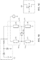
FIG. 2A depicts braking circuitry for generating braking to the motor during an emergency stop or power failure with a charge-storage circuitry not in accordance with the present invention, andFIG. 2B depicts a charge-storage circuitry of a system in accordance with the present invention; and -
FIG. 3 depicts braking circuitry employed in a two-motor driving system. - Refer first to
FIG. 1A , which illustrates arobotic system 100 having a robotic arm withjoint 102 driven by amotor 104 via agearbox 106. Rotation of themotor 104 generates low-friction motion in thegearbox 106 and is converted into a desired movement of therobotic joint 102 for performing physical manipulations. Themotor 104 may be, for example, a single-phase, two-phase, or three-phase AC permanent magnet (PM) motor or a DC PM motor (such as a three-phase brushless DC motor). In various embodiments, themotor 104 is actuated bypower circuitry 108 that is supported by a power supply 110 (e.g., 110 or 220 AC volts) and regulated by acontrol unit 112. Thecontrol unit 112 governs the speed and direction of the motor rotation to control various degrees of robotic arm motional freedom while performing robotic actions. Referring toFIG. 1B , in some embodiments, thepower circuitry 108 includes aninverter 114 having a bridge circuit (e.g., an H-bridge) to convert an input DC voltage to an output AC voltage with an adjustable amplitude and frequency; the converted output voltage is then fed from the bridge circuit to themotor 104 to cause rotation. Although a single-phase motor is described herein for simplicity, other types of motors - e.g., two-phase and three-phase motors - are within the scope of the current invention. - The illustrated bridge circuit has a first half-
bridge 116 and a second half-bridge 118, each having twosemiconductor switches channel power MOSFETs 128, as shown inFIG. 1C ; the suppressor diodes are replaced by a "body diode" that is internal to the MOSFETs and a byproduct of the device structure. When switches 122 and 124 are activated and switches 120 and 126 are deactivated, a positive voltage is applied across themotor 104; whenswitches motor 104 thus alternates during an applied power cycle. In some embodiments, thepower circuitry 108 includes charge-storage circuitry 130 to store charge when the power is on (i.e.,motor 104 is provided with power); this stored charge may be used to support braking during an emergency stop or power failure. The charge-storage circuitry 130 may have, for example, one or more capacitors or other devices that can store electric charge or energy. - During an emergency stop ("estop") or upon a power loss, the semiconductor switches in the first and second half-bridges are deactivated (or off) due to the power loss and the power circuit of the motor system is disabled. Referring to
FIG. 2A , themotor system 200 may includeemergency braking circuitry 202 as further described below. In various embodiments, areceiver circuit 208 is employed in themotor system 200 to receive an emergent signal indicating estop or power failure from a heartbeat-oscillator circuit or an operator actuated estop (not shown). Thereceiver circuit 208 subsequently transmits the signal to a pair of Schmitt-trigger gates trigger gates trigger gates receiver circuit 208, the Schmitt-trigger gates semiconductor switch 214. Alocal controller 216 may locally generate and transmit an ESTOP_ASSET signal 218 to the Schmitt-trigger gate 212 for activating thebraking circuit 202 based on fault detection functions thereof. Additionally, thelocal controller 216 may sense a remote estop condition signal through thegate 220 upon cessation of the heartbeat signal. In one embodiment, agate 220 is used to simulate the enable and disable timing for theswitch 214. - The
semiconductor switch 214 controls the activation and deactivation of theemergency braking circuitry 202. If thesemiconductor switch 214 is activated (i.e., themotor 204 is driven by the power circuitry, as described above), the voltage provided to theemergency braking circuitry 202 will be insufficient to activate it; but if thesemiconductor switch 214 is deactivated, charge stored in charge-storage circuitry 222 is converted to an output voltage sufficient to activate theemergency braking circuitry 202. In one embodiment, theemergency braking circuitry 202 includes a FET and the voltage is provided from the charge-storage circuitry 222 to the gate terminal of the FET, thereby activating the FET switch. In the illustrated embodiment, theemergency braking circuitry 202 connects to a suppressor orbody diode 224 in thebridge circuit 226 to create a short-circuit path of the motor winding. Upon an emergency stop or power loss, themotor 204 continues to rotate due to inertia; a current induced by the motor rotation flows throw the suppressor orbody diode 224 and theemergency braking circuitry 202 to dissipate the energy and thus generate motor braking. Because thebraking circuitry 202 connects to only one suppressor or body diode in the bridge circuit, the induced current is conducted away (and applies braking) every half-cycle of the motor rotation. This approach to braking has a smaller duty cycle than that of entire-cycle braking (full duty cycle), thereby allowing the motor to gradually slow down and/or respond to a back drive. In some embodiments, thebraking circuitry 202 includes a pair of transistors, each connecting to a suppressor or body diode in thebridge circuit 226 to apply full-duty cycle breaking. Accordingly, a motor-driven robotic arm can gradually return to a safe gravity-neutral position and may be moved by an external force to avoid trapping a human operator. Braking is applied until no further current is induced by the motor rotations (i.e., the motor fully stops) to ensure the safety of themotor system 200. Additionally, because the braking torque is generated by current circulation that is itself induced by the motor rotations, the braking torque is proportional to the rotational velocity of the motor. A large torque is generated when braking a high-speed rotating motor and a small torque is generated when braking a motor operating at a low speed. This further ensures safety of themotor system 200. - In various embodiments, the FET in the
emergency braking circuitry 202 is separate from the semiconductor transistor switches (e.g., 120, 122, 124, and 126 inFIG. 1B ) that switch driving currents through themotor 204; this results in the need for significantly less energy to operate the braking circuitry 202 (as compared with incorporating the emergency braking circuitry in the semiconductor switches), and operation of thebraking circuitry 202 will be easier to sustain upon power loss. The charge-storage circuitry 222, which is not in accordance with the present invention, includes a capacitor and a diode that steadily provide a gate voltage (for example, of approximately 8.2V) to the FET in theemergency braking circuitry 202 to maintain the FET gate voltage during the emergency stop or power failure. Other electronic circuitry that stores charge or energy during regular robotic operations (i.e., power on) and provides the stored charge or energy to activate theemergency braking circuitry 202 for generating motor braking without activating the semiconductor switches in the bridge circuit.
According to the present invention, emergency braking is applied to rapidly rotating joints only. Referring toFIG. 2B , the charge-storage circuitry 228, which is in accordance with the present invention, includes azener diode 230 that has a breakdown voltage of, for example, 8.2 V, and twotransistors motor power bus 236 is usually below the zener breakdown threshold voltage; thetransistor 232 thus is off. If, however, the joint is back-driven rapidly enough to regenerate a sufficient voltage above the zener breakdown threshold voltage, a current may start to flow through the BE junction of theswitch transistor 234, thereby turning on thetransistor 232 and charging thecapacitor 238. The chargedcapacitor 238 may then steadily provide a gate voltage to the FET in thebraking circuitry 202, as described above. - With reference to
FIG. 3 , the emergency braking circuit described above may be employed in a two-motor driving system 300. Avoltage signal 302 that detects the power status of a two-motor drive board 303 and asignal 304 that is regulated by a local controller (not shown) via thedrive board 303 are ORed by a pair of series-connectedNAND gates NAND gates motor drive board 303 and transmitted to twosemiconductor switches switches emergency braking circuitry motors signal 302 or anemergency signal 304 transmitted from the local controller, the semiconductor switches 310, 312 are turned off and charge-storage circuitry 322 converts the stored charge to an output voltage for activating theemergency braking circuitry emergency braking circuitry motors switches storage circuitry 322 to avoid damage to theemergency braking circuitry emergency braking circuitry emergency braking circuitry emergency braking circuitry motors - In various embodiments, the local controller may be provided as either software, hardware, or some combination thereof. For example, the controller may be an embedded-class microprocessor. In one embodiment, the motor controller includes ARM-9 core microcontrollers, on board RAM, and flash memories. Other microcontrollers (such as pulse-width modulation timers) that are optimized for motor control and provide the necessary peripherals are within the scope of the current invention. In another embodiment, the controller is implemented on one or more server-class computers, such as a PC having a CPU board containing one or more processors such as the Core Pentium or Celeron family of processors manufactured by Intel Corporation of Santa Clara, Calif. and POWER PC family of processors manufactured by Motorola Corporation of Schaumburg, I11., and/or the ATHLON line of processors manufactured by Advanced Micro Devices, Inc., of Sunnyvale, Calif. The processor may also include a main memory unit for storing programs and/or data relating to the methods described above. The memory may include random access memory (RAM), read only memory (ROM), and/or FLASH memory residing on commonly available hardware such as one or more application specific integrated circuits (ASIC), field programmable gate arrays (FPGA), electrically erasable programmable read-only memories (EEPROM), programmable read-only memories (PROM), or programmable logic devices (PLD). In some embodiments, the programs may be provided using external RAM and/or ROM such as optical disks, magnetic disks, as well as other commonly used storage devices.
- For embodiments in which the local controller is provided as a software program, the program may be written in any one of a number of high level languages such as FORTRAN, PASCAL, JAVA, C, C++, C#, LISP, PERL, BASIC, PYTHON or any suitable programming language. Additionally, the software can be implemented in an assembly language and/or machine language directed to the microprocessor resident on a target device.
- The terms and expressions employed herein are used as terms and expressions of description and not of limitation, and there is no intention, in the use of such terms and expressions, of excluding any equivalents of the features shown and described or portions thereof. In addition, having described certain embodiments of the invention, it will be apparent to those of ordinary skill in the art that other embodiments may be used without departing from the scope of invention as defined in the appended claims. Accordingly, the described embodiments are to be considered in all respects as only illustrative and not restrictive.
Claims (15)
- An unpowered braking system for braking a cyclically rotating motor (204) upon a power failure, the system comprising:charge-storage circuitry (228) for storing charge and converting the stored charge to an output voltage upon power failure;at least one passive electrical element (224) for conducting current induced by motor rotations;andvoltage-actuated circuitry (202), connected to the passive electrical element and the charge-storage circuitry, for braking the motor, the circuitry being inactive until actuated by the charge-storage circuitry upon power failure, and characterized in that the charge-storage circuitry comprises a zener diode (230) having a breakdown voltage threshold and at least one transistor (232,234), wherein the at least one transistor is inactive until actuated by a sufficient voltage above the zener breakdown threshold voltage.
- The system of claim 1, wherein the voltage-actuated circuitry brakes the motor by short-circuiting a motor winding by causing current to flow therethrough.
- The system of claim 1, further comprising a bridge inverter having a plurality of transistors, wherein the transistors are deactivated upon power failure.
- The system of claim 1, further comprising a logic gate to control activation and deactivation of the voltage-actuated circuitry.
- The system of claim 4, wherein the logic gate is regulated by at least one of a controller or a signal indicating a power status.
- The system of claim 5, wherein the voltage-actuated circuitry is activated when an output of the logic gate is below a predetermined minimum voltage threshold.
- The system of claim 5, wherein the voltage-actuated circuitry is deactivated when an output of the logic gate is above a predetermined maximum voltage threshold.
- The system of claim 1, wherein the charge-storage circuitry comprises a capacitor (238).
- The system of claim 1, wherein the passive electrical element comprises a diode.
- The system of claim 1, wherein the voltage-actuated circuitry comprises a transistor.
- The system of claim 1, wherein the voltage-actuated circuitry is activated each half-cycle or at a full-duty cycle of motor rotation.
- A method of generating motor braking upon a power failure, the method comprising:storing charge in a charge-storage circuitry (228); converting the stored charge to an output voltage upon the power failure;applying the voltage to short-circuit a motor winding by causing current to flow therethrough,thereby braking the motor (204); and characterized by actuating a transistor (232,234) in the charge storage circuitry (228) by a sufficient voltage above a zener breakdown threshold voltage of a zener diode (230).
- The method of claim 12, wherein the motor winding is short-circuited each half-cycle of motor rotation.
- The method of claim 12, wherein the motor winding is short-circuited at a full-duty cycle of motor rotation.
- The method of claim 12, wherein the motor winding is short-circuited when a speed of motor rotation is above a threshold value.
Applications Claiming Priority (2)
| Application Number | Priority Date | Filing Date | Title |
|---|---|---|---|
| US13/446,650 US9114536B2 (en) | 2012-04-13 | 2012-04-13 | Electronic emergency-stop braking circuit for robotic arms |
| PCT/US2013/035709 WO2013155034A2 (en) | 2012-04-13 | 2013-04-09 | Electronic emergency-stop braking circuit for robotic arms |
Publications (2)
| Publication Number | Publication Date |
|---|---|
| EP2836339A2 EP2836339A2 (en) | 2015-02-18 |
| EP2836339B1 true EP2836339B1 (en) | 2017-07-12 |
Family
ID=48464066
Family Applications (1)
| Application Number | Title | Priority Date | Filing Date |
|---|---|---|---|
| EP13723582.6A Active EP2836339B1 (en) | 2012-04-13 | 2013-04-09 | Electronic emergency-stop braking circuit for robotic arms |
Country Status (5)
| Country | Link |
|---|---|
| US (1) | US9114536B2 (en) |
| EP (1) | EP2836339B1 (en) |
| JP (1) | JP6176865B2 (en) |
| CN (1) | CN104245251B (en) |
| WO (1) | WO2013155034A2 (en) |
Families Citing this family (30)
| Publication number | Priority date | Publication date | Assignee | Title |
|---|---|---|---|---|
| US9114536B2 (en) | 2012-04-13 | 2015-08-25 | Rethink Robotics, Inc. | Electronic emergency-stop braking circuit for robotic arms |
| JP6051021B2 (en) * | 2012-08-09 | 2016-12-21 | 日本電産サンキョー株式会社 | Industrial robot and control method for industrial robot |
| JP2014138532A (en) * | 2013-01-18 | 2014-07-28 | Fuji Electric Co Ltd | Electric power conversion system |
| WO2015023263A1 (en) * | 2013-08-13 | 2015-02-19 | Otis Elevator Company | Elevator braking in a battery powered elevator system |
| TWI513907B (en) * | 2013-12-26 | 2015-12-21 | Delta Electronics Inc | Fan motor braking apparatus and method of controlling the same |
| GB201504506D0 (en) | 2015-03-17 | 2015-04-29 | Cambridge Medical Robotics Ltd | A motor arrangement |
| US9962833B2 (en) * | 2015-04-07 | 2018-05-08 | Mtm Robotics, Llc | System and method for adjusting end-effector actuation based on relative position with respect to gravitational force |
| JP6513006B2 (en) * | 2015-09-30 | 2019-05-15 | 株式会社マキタ | Motor control device |
| DE102015116609A1 (en) * | 2015-09-30 | 2017-03-30 | Sami Haddadin | joint device |
| US10252421B2 (en) | 2015-10-06 | 2019-04-09 | Mtm Robotics Llc | Self-contained modular manufacturing tool |
| US10220516B2 (en) | 2015-10-06 | 2019-03-05 | Mtm Robotics, Llc | System and method for self-contained independently controlled modular manufacturing tools |
| US10025299B2 (en) | 2015-10-06 | 2018-07-17 | Mtm Robotics, Llc | System and method for self-contained modular manufacturing device having nested controllers |
| US10022872B2 (en) | 2015-10-06 | 2018-07-17 | Mtm Robotics, Llc | Self-contained modular manufacturing tool responsive to locally stored historical data |
| US10848080B2 (en) * | 2016-08-08 | 2020-11-24 | Nidec Servo Corporation | Motor drive circuit |
| CN107877514A (en) * | 2017-10-20 | 2018-04-06 | 深圳市睿科智联科技有限公司 | A kind of flexible braking circuit, robot arm and robot for robot arm |
| JP6964024B2 (en) * | 2018-03-19 | 2021-11-10 | 川崎重工業株式会社 | Short circuit device and robot system equipped with it |
| US10682770B1 (en) * | 2018-06-20 | 2020-06-16 | Amazon Technologies, Inc. | Articulating suction cup tool |
| CN110039574B (en) * | 2019-04-24 | 2021-02-05 | 北京猎户星空科技有限公司 | Robot braking circuit, robot braking method and device |
| JP7299099B2 (en) * | 2019-08-06 | 2023-06-27 | ニデックインスツルメンツ株式会社 | Robot stopping method and robot system |
| GB2588175B (en) * | 2019-10-11 | 2023-11-01 | Cmr Surgical Ltd | Fault detection response in a robot arm |
| JP2022042126A (en) * | 2020-09-02 | 2022-03-14 | セイコーエプソン株式会社 | Robot control device and robot system |
| TWI758926B (en) * | 2020-10-27 | 2022-03-21 | 達明機器人股份有限公司 | Safety monitor system and method for diagnosing abnormality of the same in robot |
| CN113017666A (en) * | 2021-02-05 | 2021-06-25 | 明峰医疗系统股份有限公司 | Anti-falling brake circuit of diagnostic bed and CT scanning bed |
| US11777602B2 (en) | 2021-11-09 | 2023-10-03 | Nidec Motor Corporation | Apparatus and method for arbitrating optical communication between can buses |
| US12074552B2 (en) | 2021-11-09 | 2024-08-27 | Nidec Motor Corporation | Dual encoder system for electric motor |
| US11855572B2 (en) | 2021-11-09 | 2023-12-26 | Nidec Motor Corporation | System and method for increasing braking performance under multi-phase shorting |
| US11784589B2 (en) | 2021-11-09 | 2023-10-10 | Nidec Motor Corporation | Safety switching system and method for braking electric motor |
| US11938628B2 (en) | 2021-11-19 | 2024-03-26 | Boston Dynamics, Inc. | Systems and methods for controlling movements of robotic actuators |
| GB2629369A (en) * | 2023-04-25 | 2024-10-30 | Dyson Technology Ltd | Robot |
| CN118744642A (en) * | 2024-07-17 | 2024-10-08 | 杭州林奇电控有限公司 | A detection and control method for emergency braking of a brushed DC motor during power failure |
Family Cites Families (37)
| Publication number | Priority date | Publication date | Assignee | Title |
|---|---|---|---|---|
| JPS59172984A (en) * | 1983-03-22 | 1984-09-29 | Mitsubishi Electric Corp | Controller of ac elevator |
| JPS6042099U (en) * | 1983-08-25 | 1985-03-25 | 株式会社東芝 | Electric motor braking device |
| US4767970A (en) | 1986-12-22 | 1988-08-30 | Ampex Corporation | Dynamic brake control for a tape drive system |
| US4831469A (en) * | 1987-07-29 | 1989-05-16 | International Business Machines Corporation | Disk drive head retract and motor braking method and apparatus |
| JPH0223080A (en) | 1988-07-08 | 1990-01-25 | Meidensha Corp | Braking system for robot |
| JPH0366589A (en) | 1989-05-31 | 1991-03-22 | An Ey-Rang | Drive control circuit for robot |
| JP2730206B2 (en) | 1989-09-01 | 1998-03-25 | 松下電器産業株式会社 | Motor control device |
| US5117166A (en) * | 1991-03-28 | 1992-05-26 | General Electric Company | Chopper circuit for dynamic braking in an electric power conversion system |
| JPH05192027A (en) * | 1991-11-22 | 1993-08-03 | Sawafuji Electric Co Ltd | Electric lawn mower |
| US6548973B1 (en) * | 1997-01-15 | 2003-04-15 | Texas Instruments Incorporated | Method and apparatus for braking a polyphase DC motor |
| US6097225A (en) * | 1998-07-14 | 2000-08-01 | National Semiconductor Corporation | Mixed signal circuit with analog circuits producing valid reference signals |
| CA2244340C (en) * | 1998-07-29 | 2002-02-12 | J. Fred Westlake | Dynamic braking system for a motorized lifting mechanism |
| US6169391B1 (en) * | 1999-07-12 | 2001-01-02 | Supertex, Inc. | Device for converting high voltage alternating current to low voltage direct current |
| US6310452B1 (en) * | 2000-06-09 | 2001-10-30 | Tyco Electronics Corp | Single cycle positioning system utilizing a DC motor |
| DE10059173C5 (en) | 2000-11-29 | 2004-07-15 | Siemens Ag | Drive control for a three-phase motor via an inverter using safe technology |
| US6943510B2 (en) * | 2001-08-06 | 2005-09-13 | Black & Decker Inc. | Excitation circuit and control method for flux switching motor |
| CN1305648C (en) | 2002-04-12 | 2007-03-21 | 三菱电机株式会社 | manipulator |
| JP2003348868A (en) * | 2002-05-23 | 2003-12-05 | Yaskawa Electric Corp | Dynamic brake circuit |
| AU2002952885A0 (en) * | 2002-11-25 | 2002-12-12 | Turbocor Inc | High speed electric motor power supply |
| KR100488528B1 (en) * | 2003-05-16 | 2005-05-11 | 삼성전자주식회사 | Power supply device for motor |
| US7309967B2 (en) * | 2004-03-31 | 2007-12-18 | Hitachi Global Storage Technologies Netherlands B.V. | Motor drive circuitry with regenerative braking for disk drive |
| JP4661188B2 (en) * | 2004-11-25 | 2011-03-30 | 富士電機システムズ株式会社 | Door opener |
| JP4202335B2 (en) * | 2005-03-22 | 2008-12-24 | ファナック株式会社 | Emergency stop circuit |
| JP4581892B2 (en) | 2005-07-27 | 2010-11-17 | 株式会社デンソーウェーブ | Robot controller |
| US7554276B2 (en) * | 2005-09-21 | 2009-06-30 | International Rectifier Corporation | Protection circuit for permanent magnet synchronous motor in field weakening operation |
| JP4202384B2 (en) * | 2006-11-21 | 2008-12-24 | ファナック株式会社 | Motor drive device for driving and braking a motor with a brake |
| EP1974870A1 (en) | 2007-03-30 | 2008-10-01 | Abb Research Ltd. | An industrial robot having a plurality of independently controlled electromagnetic brakes |
| DE102007049162A1 (en) | 2007-08-30 | 2009-03-05 | Robert Bosch Gmbh | Device for operating a machine |
| DE102007059492B4 (en) | 2007-12-11 | 2018-06-28 | Kuka Deutschland Gmbh | industrial robots |
| CN101909829B (en) | 2008-02-28 | 2012-08-29 | 松下电器产业株式会社 | Robot arm control device and control method, robot, robot arm control program, and integrated electronic circuit for robot arm control |
| DE102008054501A1 (en) | 2008-12-10 | 2010-06-17 | Kuka Roboter Gmbh | Industrial robots and method for operating an industrial robot |
| US8093844B2 (en) * | 2009-03-12 | 2012-01-10 | Allegro Microsystems, Inc. | Braking function for brushless DC motor control |
| US8412272B2 (en) * | 2009-07-24 | 2013-04-02 | T-Mobile Usa, Inc. | Rectifier circuit management system, such as for use in cell site power systems |
| TWI437239B (en) * | 2010-04-07 | 2014-05-11 | Richpower Microelectronics | Voltage detector and protection apparatus using the voltage detector |
| JP4955791B2 (en) | 2010-04-20 | 2012-06-20 | ファナック株式会社 | Robot system |
| JP2013090415A (en) * | 2011-10-17 | 2013-05-13 | Semiconductor Components Industries Llc | Motor drive circuit |
| US9114536B2 (en) | 2012-04-13 | 2015-08-25 | Rethink Robotics, Inc. | Electronic emergency-stop braking circuit for robotic arms |
-
2012
- 2012-04-13 US US13/446,650 patent/US9114536B2/en active Active
-
2013
- 2013-04-09 CN CN201380019810.5A patent/CN104245251B/en active Active
- 2013-04-09 JP JP2015505844A patent/JP6176865B2/en active Active
- 2013-04-09 EP EP13723582.6A patent/EP2836339B1/en active Active
- 2013-04-09 WO PCT/US2013/035709 patent/WO2013155034A2/en not_active Ceased
Also Published As
| Publication number | Publication date |
|---|---|
| JP6176865B2 (en) | 2017-08-09 |
| EP2836339A2 (en) | 2015-02-18 |
| US20130271046A1 (en) | 2013-10-17 |
| US9114536B2 (en) | 2015-08-25 |
| JP2015519857A (en) | 2015-07-09 |
| WO2013155034A3 (en) | 2013-12-05 |
| CN104245251B (en) | 2016-05-25 |
| CN104245251A (en) | 2014-12-24 |
| WO2013155034A2 (en) | 2013-10-17 |
Similar Documents
| Publication | Publication Date | Title |
|---|---|---|
| US9114536B2 (en) | Electronic emergency-stop braking circuit for robotic arms | |
| EP3272002B1 (en) | Robotic system with a motor arrangement | |
| KR101236083B1 (en) | Industrial robot having redundant emergency brake circuit | |
| US9676103B2 (en) | Multi-axis robot power shut-off device and multi-axis robot | |
| CN101485076B (en) | Method for controlling a deceleration process of a DC motor and controller | |
| CN114465526B (en) | Control device for electric motor, robot equipped with the control device, and control method of electric motor | |
| CN105583828A (en) | Method And System For Stopping Of Axes Of An Industrial Robot | |
| US10840899B2 (en) | Motor drive device and electric power steering device | |
| WO2016085862A1 (en) | Motor braking system and method for power tools | |
| EP2374580B1 (en) | Electric gripper drive with a torsional compliance device | |
| JP7223747B2 (en) | drive for vehicle flaps | |
| JP7364919B2 (en) | Brake circuit discharge system | |
| WO2018153327A1 (en) | Control circuit applicable to motor, and electric tool | |
| NO342871B1 (en) | Control system and method for an electric actuator with fail-safe functionality | |
| JP7507608B2 (en) | ROBOT, ROBOT CONTROL DEVICE, AND ROBOT CONTROL METHOD | |
| RU2321153C1 (en) | Device for braking an electric motor | |
| JP2010057245A (en) | Motor controller equipped with emergency shutdown system | |
| CN119995470A (en) | Motor control method, system, device, vehicle, medium and product |
Legal Events
| Date | Code | Title | Description |
|---|---|---|---|
| PUAI | Public reference made under article 153(3) epc to a published international application that has entered the european phase |
Free format text: ORIGINAL CODE: 0009012 |
|
| 17P | Request for examination filed |
Effective date: 20141106 |
|
| AK | Designated contracting states |
Kind code of ref document: A2 Designated state(s): AL AT BE BG CH CY CZ DE DK EE ES FI FR GB GR HR HU IE IS IT LI LT LU LV MC MK MT NL NO PL PT RO RS SE SI SK SM TR |
|
| AX | Request for extension of the european patent |
Extension state: BA ME |
|
| DAX | Request for extension of the european patent (deleted) | ||
| RAP1 | Party data changed (applicant data changed or rights of an application transferred) |
Owner name: RETHINK ROBOTICS INC. |
|
| GRAP | Despatch of communication of intention to grant a patent |
Free format text: ORIGINAL CODE: EPIDOSNIGR1 |
|
| INTG | Intention to grant announced |
Effective date: 20170201 |
|
| GRAS | Grant fee paid |
Free format text: ORIGINAL CODE: EPIDOSNIGR3 |
|
| GRAA | (expected) grant |
Free format text: ORIGINAL CODE: 0009210 |
|
| AK | Designated contracting states |
Kind code of ref document: B1 Designated state(s): AL AT BE BG CH CY CZ DE DK EE ES FI FR GB GR HR HU IE IS IT LI LT LU LV MC MK MT NL NO PL PT RO RS SE SI SK SM TR |
|
| REG | Reference to a national code |
Ref country code: GB Ref legal event code: FG4D |
|
| REG | Reference to a national code |
Ref country code: CH Ref legal event code: EP |
|
| REG | Reference to a national code |
Ref country code: AT Ref legal event code: REF Ref document number: 907889 Country of ref document: AT Kind code of ref document: T Effective date: 20170715 |
|
| REG | Reference to a national code |
Ref country code: IE Ref legal event code: FG4D |
|
| REG | Reference to a national code |
Ref country code: DE Ref legal event code: R096 Ref document number: 602013023396 Country of ref document: DE |
|
| REG | Reference to a national code |
Ref country code: NL Ref legal event code: MP Effective date: 20170712 |
|
| REG | Reference to a national code |
Ref country code: LT Ref legal event code: MG4D |
|
| REG | Reference to a national code |
Ref country code: AT Ref legal event code: MK05 Ref document number: 907889 Country of ref document: AT Kind code of ref document: T Effective date: 20170712 |
|
| PG25 | Lapsed in a contracting state [announced via postgrant information from national office to epo] |
Ref country code: NL Free format text: LAPSE BECAUSE OF FAILURE TO SUBMIT A TRANSLATION OF THE DESCRIPTION OR TO PAY THE FEE WITHIN THE PRESCRIBED TIME-LIMIT Effective date: 20170712 Ref country code: AT Free format text: LAPSE BECAUSE OF FAILURE TO SUBMIT A TRANSLATION OF THE DESCRIPTION OR TO PAY THE FEE WITHIN THE PRESCRIBED TIME-LIMIT Effective date: 20170712 Ref country code: SE Free format text: LAPSE BECAUSE OF FAILURE TO SUBMIT A TRANSLATION OF THE DESCRIPTION OR TO PAY THE FEE WITHIN THE PRESCRIBED TIME-LIMIT Effective date: 20170712 Ref country code: HR Free format text: LAPSE BECAUSE OF FAILURE TO SUBMIT A TRANSLATION OF THE DESCRIPTION OR TO PAY THE FEE WITHIN THE PRESCRIBED TIME-LIMIT Effective date: 20170712 Ref country code: NO Free format text: LAPSE BECAUSE OF FAILURE TO SUBMIT A TRANSLATION OF THE DESCRIPTION OR TO PAY THE FEE WITHIN THE PRESCRIBED TIME-LIMIT Effective date: 20171012 Ref country code: LT Free format text: LAPSE BECAUSE OF FAILURE TO SUBMIT A TRANSLATION OF THE DESCRIPTION OR TO PAY THE FEE WITHIN THE PRESCRIBED TIME-LIMIT Effective date: 20170712 Ref country code: FI Free format text: LAPSE BECAUSE OF FAILURE TO SUBMIT A TRANSLATION OF THE DESCRIPTION OR TO PAY THE FEE WITHIN THE PRESCRIBED TIME-LIMIT Effective date: 20170712 |
|
| PG25 | Lapsed in a contracting state [announced via postgrant information from national office to epo] |
Ref country code: PL Free format text: LAPSE BECAUSE OF FAILURE TO SUBMIT A TRANSLATION OF THE DESCRIPTION OR TO PAY THE FEE WITHIN THE PRESCRIBED TIME-LIMIT Effective date: 20170712 Ref country code: LV Free format text: LAPSE BECAUSE OF FAILURE TO SUBMIT A TRANSLATION OF THE DESCRIPTION OR TO PAY THE FEE WITHIN THE PRESCRIBED TIME-LIMIT Effective date: 20170712 Ref country code: ES Free format text: LAPSE BECAUSE OF FAILURE TO SUBMIT A TRANSLATION OF THE DESCRIPTION OR TO PAY THE FEE WITHIN THE PRESCRIBED TIME-LIMIT Effective date: 20170712 Ref country code: IS Free format text: LAPSE BECAUSE OF FAILURE TO SUBMIT A TRANSLATION OF THE DESCRIPTION OR TO PAY THE FEE WITHIN THE PRESCRIBED TIME-LIMIT Effective date: 20171112 Ref country code: BG Free format text: LAPSE BECAUSE OF FAILURE TO SUBMIT A TRANSLATION OF THE DESCRIPTION OR TO PAY THE FEE WITHIN THE PRESCRIBED TIME-LIMIT Effective date: 20171012 Ref country code: RS Free format text: LAPSE BECAUSE OF FAILURE TO SUBMIT A TRANSLATION OF THE DESCRIPTION OR TO PAY THE FEE WITHIN THE PRESCRIBED TIME-LIMIT Effective date: 20170712 Ref country code: GR Free format text: LAPSE BECAUSE OF FAILURE TO SUBMIT A TRANSLATION OF THE DESCRIPTION OR TO PAY THE FEE WITHIN THE PRESCRIBED TIME-LIMIT Effective date: 20171013 |
|
| REG | Reference to a national code |
Ref country code: DE Ref legal event code: R097 Ref document number: 602013023396 Country of ref document: DE |
|
| REG | Reference to a national code |
Ref country code: FR Ref legal event code: PLFP Year of fee payment: 6 |
|
| PG25 | Lapsed in a contracting state [announced via postgrant information from national office to epo] |
Ref country code: DK Free format text: LAPSE BECAUSE OF FAILURE TO SUBMIT A TRANSLATION OF THE DESCRIPTION OR TO PAY THE FEE WITHIN THE PRESCRIBED TIME-LIMIT Effective date: 20170712 Ref country code: CZ Free format text: LAPSE BECAUSE OF FAILURE TO SUBMIT A TRANSLATION OF THE DESCRIPTION OR TO PAY THE FEE WITHIN THE PRESCRIBED TIME-LIMIT Effective date: 20170712 Ref country code: RO Free format text: LAPSE BECAUSE OF FAILURE TO SUBMIT A TRANSLATION OF THE DESCRIPTION OR TO PAY THE FEE WITHIN THE PRESCRIBED TIME-LIMIT Effective date: 20170712 |
|
| PLBE | No opposition filed within time limit |
Free format text: ORIGINAL CODE: 0009261 |
|
| STAA | Information on the status of an ep patent application or granted ep patent |
Free format text: STATUS: NO OPPOSITION FILED WITHIN TIME LIMIT |
|
| PG25 | Lapsed in a contracting state [announced via postgrant information from national office to epo] |
Ref country code: SM Free format text: LAPSE BECAUSE OF FAILURE TO SUBMIT A TRANSLATION OF THE DESCRIPTION OR TO PAY THE FEE WITHIN THE PRESCRIBED TIME-LIMIT Effective date: 20170712 Ref country code: EE Free format text: LAPSE BECAUSE OF FAILURE TO SUBMIT A TRANSLATION OF THE DESCRIPTION OR TO PAY THE FEE WITHIN THE PRESCRIBED TIME-LIMIT Effective date: 20170712 Ref country code: IT Free format text: LAPSE BECAUSE OF FAILURE TO SUBMIT A TRANSLATION OF THE DESCRIPTION OR TO PAY THE FEE WITHIN THE PRESCRIBED TIME-LIMIT Effective date: 20170712 Ref country code: SK Free format text: LAPSE BECAUSE OF FAILURE TO SUBMIT A TRANSLATION OF THE DESCRIPTION OR TO PAY THE FEE WITHIN THE PRESCRIBED TIME-LIMIT Effective date: 20170712 |
|
| 26N | No opposition filed |
Effective date: 20180413 |
|
| PG25 | Lapsed in a contracting state [announced via postgrant information from national office to epo] |
Ref country code: SI Free format text: LAPSE BECAUSE OF FAILURE TO SUBMIT A TRANSLATION OF THE DESCRIPTION OR TO PAY THE FEE WITHIN THE PRESCRIBED TIME-LIMIT Effective date: 20170712 |
|
| PG25 | Lapsed in a contracting state [announced via postgrant information from national office to epo] |
Ref country code: MC Free format text: LAPSE BECAUSE OF FAILURE TO SUBMIT A TRANSLATION OF THE DESCRIPTION OR TO PAY THE FEE WITHIN THE PRESCRIBED TIME-LIMIT Effective date: 20170712 |
|
| REG | Reference to a national code |
Ref country code: CH Ref legal event code: PL |
|
| REG | Reference to a national code |
Ref country code: BE Ref legal event code: MM Effective date: 20180430 |
|
| REG | Reference to a national code |
Ref country code: DE Ref legal event code: R082 Ref document number: 602013023396 Country of ref document: DE Representative=s name: GRUENECKER PATENT- UND RECHTSANWAELTE PARTG MB, DE |
|
| REG | Reference to a national code |
Ref country code: IE Ref legal event code: MM4A |
|
| PG25 | Lapsed in a contracting state [announced via postgrant information from national office to epo] |
Ref country code: LU Free format text: LAPSE BECAUSE OF NON-PAYMENT OF DUE FEES Effective date: 20180409 |
|
| PG25 | Lapsed in a contracting state [announced via postgrant information from national office to epo] |
Ref country code: LI Free format text: LAPSE BECAUSE OF NON-PAYMENT OF DUE FEES Effective date: 20180430 Ref country code: CH Free format text: LAPSE BECAUSE OF NON-PAYMENT OF DUE FEES Effective date: 20180430 Ref country code: BE Free format text: LAPSE BECAUSE OF NON-PAYMENT OF DUE FEES Effective date: 20180430 |
|
| REG | Reference to a national code |
Ref country code: DE Ref legal event code: R082 Ref document number: 602013023396 Country of ref document: DE Representative=s name: GRUENECKER PATENT- UND RECHTSANWAELTE PARTG MB, DE Ref country code: DE Ref legal event code: R081 Ref document number: 602013023396 Country of ref document: DE Owner name: RETHINK ROBOTICS GMBH, DE Free format text: FORMER OWNER: RETHINK ROBOTICS INC., BOSTON, MASS., US |
|
| PG25 | Lapsed in a contracting state [announced via postgrant information from national office to epo] |
Ref country code: IE Free format text: LAPSE BECAUSE OF NON-PAYMENT OF DUE FEES Effective date: 20180409 |
|
| REG | Reference to a national code |
Ref country code: GB Ref legal event code: 732E Free format text: REGISTERED BETWEEN 20191212 AND 20191218 |
|
| PG25 | Lapsed in a contracting state [announced via postgrant information from national office to epo] |
Ref country code: MT Free format text: LAPSE BECAUSE OF NON-PAYMENT OF DUE FEES Effective date: 20180409 |
|
| PG25 | Lapsed in a contracting state [announced via postgrant information from national office to epo] |
Ref country code: TR Free format text: LAPSE BECAUSE OF FAILURE TO SUBMIT A TRANSLATION OF THE DESCRIPTION OR TO PAY THE FEE WITHIN THE PRESCRIBED TIME-LIMIT Effective date: 20170712 |
|
| PG25 | Lapsed in a contracting state [announced via postgrant information from national office to epo] |
Ref country code: PT Free format text: LAPSE BECAUSE OF FAILURE TO SUBMIT A TRANSLATION OF THE DESCRIPTION OR TO PAY THE FEE WITHIN THE PRESCRIBED TIME-LIMIT Effective date: 20170712 Ref country code: HU Free format text: LAPSE BECAUSE OF FAILURE TO SUBMIT A TRANSLATION OF THE DESCRIPTION OR TO PAY THE FEE WITHIN THE PRESCRIBED TIME-LIMIT; INVALID AB INITIO Effective date: 20130409 |
|
| PG25 | Lapsed in a contracting state [announced via postgrant information from national office to epo] |
Ref country code: CY Free format text: LAPSE BECAUSE OF FAILURE TO SUBMIT A TRANSLATION OF THE DESCRIPTION OR TO PAY THE FEE WITHIN THE PRESCRIBED TIME-LIMIT Effective date: 20170712 Ref country code: MK Free format text: LAPSE BECAUSE OF NON-PAYMENT OF DUE FEES Effective date: 20170712 |
|
| PG25 | Lapsed in a contracting state [announced via postgrant information from national office to epo] |
Ref country code: AL Free format text: LAPSE BECAUSE OF FAILURE TO SUBMIT A TRANSLATION OF THE DESCRIPTION OR TO PAY THE FEE WITHIN THE PRESCRIBED TIME-LIMIT Effective date: 20170712 |
|
| PGFP | Annual fee paid to national office [announced via postgrant information from national office to epo] |
Ref country code: DE Payment date: 20250425 Year of fee payment: 13 |
|
| PGFP | Annual fee paid to national office [announced via postgrant information from national office to epo] |
Ref country code: GB Payment date: 20250426 Year of fee payment: 13 |
|
| PGFP | Annual fee paid to national office [announced via postgrant information from national office to epo] |
Ref country code: FR Payment date: 20250426 Year of fee payment: 13 |