EP2836308B1 - Powder spray gun comprising a wear resistant electrode support - Google Patents
Powder spray gun comprising a wear resistant electrode support Download PDFInfo
- Publication number
- EP2836308B1 EP2836308B1 EP13715784.8A EP13715784A EP2836308B1 EP 2836308 B1 EP2836308 B1 EP 2836308B1 EP 13715784 A EP13715784 A EP 13715784A EP 2836308 B1 EP2836308 B1 EP 2836308B1
- Authority
- EP
- European Patent Office
- Prior art keywords
- powder
- sleeve
- spray gun
- electrode
- compliant
- Prior art date
- Legal status (The legal status is an assumption and is not a legal conclusion. Google has not performed a legal analysis and makes no representation as to the accuracy of the status listed.)
- Revoked
Links
Images


Classifications
-
- B—PERFORMING OPERATIONS; TRANSPORTING
- B05—SPRAYING OR ATOMISING IN GENERAL; APPLYING FLUENT MATERIALS TO SURFACES, IN GENERAL
- B05B—SPRAYING APPARATUS; ATOMISING APPARATUS; NOZZLES
- B05B5/00—Electrostatic spraying apparatus; Spraying apparatus with means for charging the spray electrically; Apparatus for spraying liquids or other fluent materials by other electric means
- B05B5/025—Discharge apparatus, e.g. electrostatic spray guns
- B05B5/03—Discharge apparatus, e.g. electrostatic spray guns characterised by the use of gas, e.g. electrostatically assisted pneumatic spraying
- B05B5/032—Discharge apparatus, e.g. electrostatic spray guns characterised by the use of gas, e.g. electrostatically assisted pneumatic spraying for spraying particulate materials
-
- B—PERFORMING OPERATIONS; TRANSPORTING
- B05—SPRAYING OR ATOMISING IN GENERAL; APPLYING FLUENT MATERIALS TO SURFACES, IN GENERAL
- B05B—SPRAYING APPARATUS; ATOMISING APPARATUS; NOZZLES
- B05B15/00—Details of spraying plant or spraying apparatus not otherwise provided for; Accessories
- B05B15/14—Arrangements for preventing or controlling structural damage to spraying apparatus or its outlets, e.g. for breaking at desired places; Arrangements for handling or replacing damaged parts
- B05B15/18—Arrangements for preventing or controlling structural damage to spraying apparatus or its outlets, e.g. for breaking at desired places; Arrangements for handling or replacing damaged parts for improving resistance to wear, e.g. inserts or coatings; for indicating wear; for handling or replacing worn parts
-
- B—PERFORMING OPERATIONS; TRANSPORTING
- B05—SPRAYING OR ATOMISING IN GENERAL; APPLYING FLUENT MATERIALS TO SURFACES, IN GENERAL
- B05B—SPRAYING APPARATUS; ATOMISING APPARATUS; NOZZLES
- B05B5/00—Electrostatic spraying apparatus; Spraying apparatus with means for charging the spray electrically; Apparatus for spraying liquids or other fluent materials by other electric means
- B05B5/025—Discharge apparatus, e.g. electrostatic spray guns
- B05B5/053—Arrangements for supplying power, e.g. charging power
- B05B5/0533—Electrodes specially adapted therefor; Arrangements of electrodes
-
- B—PERFORMING OPERATIONS; TRANSPORTING
- B05—SPRAYING OR ATOMISING IN GENERAL; APPLYING FLUENT MATERIALS TO SURFACES, IN GENERAL
- B05B—SPRAYING APPARATUS; ATOMISING APPARATUS; NOZZLES
- B05B7/00—Spraying apparatus for discharge of liquids or other fluent materials from two or more sources, e.g. of liquid and air, of powder and gas
- B05B7/02—Spray pistols; Apparatus for discharge
- B05B7/025—Nozzles having elongated outlets, e.g. slots, for the material to be sprayed
Definitions
- the disclosure relates generally to material application devices used for spraying powder coating material onto a work piece or object. More particularly, the disclosure relates to material application devices for spraying porcelain enamel or other abrasive powder coating material.
- a material application device is used to apply powder coating material to an object, part or other work piece or surface.
- a material application device is also referred to herein as a spray gun.
- Spray guns are often used to apply organic powder coating material.
- Porcelain enamel coating material is a fine glass powder-like material, but is unlike organic powder coating material made from plastics and polymers.
- Organic powder may be characterized by lower melting temperatures as compared to porcelain enamel powder, and organic powders tend to be lighter, often exhibit impact fusion and have a fairly high transfer ratio or efficiency (transfer ratio or efficiency refers to the percentage of powder coating material that adheres to the work piece during a coating or spraying operation).
- Organic powder can have higher transfer ratios, along the order of seventy to eighty percent, because polymer and plastic materials are receptive to electrostatic charge applied to the powder by the spray gun. Porcelain enamel coating materials are difficult to apply an electrostatic charge, thereby exhibiting lower transfer ratios along the order of twenty percent, tend to be heavier than organic powder coating materials, and are highly abrasive because they comprise fine glass particles.
- EP 1084759 discloses a powder spray gun with one part housing insert formed e.g. of plastic which supports a spider insert which holds and aligns an electrode.
- DE 29924481 U discloses a spray gun with an electrode holder formed as a one part body of electrically insulating material, e.g. plastic.
- the invention may be used with a spray gun for spraying abrasive materials, for example, porcelain enamel powder.
- a spray gun for spraying abrasive materials
- various inventive aspects disclosed herein may alternatively be used for spraying organic powder or other non-porcelain enamel materials.
- the invention may be used with automatic spray guns or alternatively manual spray guns.
- the invention may also be used with spray guns that have different mounting configurations, including but not limited to bar mount and tube mount configurations.
- a spray gun for spraying porcelain enamel powder coating materials
- the embodiments are not limited to such material, and will find application in other spray coating systems using powders that may be organic or glass or other compositions.
- a spray gun is illustrated herein as an automatic gun, and more particularly an automatic spray gun in a bar mount configuration
- the embodiments may also be conveniently used with manual spray guns, as well as automatic guns with other mounting or support configurations, including but not limited to tube mount.
- the embodiments described herein relate to components associated at the spray end or outlet of the spray gun, such as the spray nozzle, an electrode assembly and so on. Therefore, the embodiments may readily be adapted to other spray gun configurations.
- the exemplary embodiments utilize ceramic as a wear resistant material for some parts that are exposed to flow of an abrasive powder coating material. But those skilled in the art will readily understand that ceramic is only one example of a wear resistant material that may be used for such parts. Other wear resistant materials may be used as needed, for example, borosilicate glass such as PYREXTM and hardened steels, such as steel having a Rockwell C hardness in the upper sixties or more.
- the electrode assembly is preferably in-line with the powder flow axis into the spray nozzle assembly.
- the in-line configuration of the electrode assembly reduces direct impact of abrasive powder coating material on interior surfaces of the spray nozzle assembly.
- the in-line configuration of the electrode assembly facilitates use of a compliant member or sleeve that is made of an elastically compliant material, to position and support the electrode assembly at a desired location. Additional embodiments of this concept are presented herein.
- a powder flow path may optionally extend along a single powder flow axis from an inlet end of a spray gun body into a spray nozzle at an outlet end of the spray gun body wherein the spray nozzle has a powder flow axis into the spray nozzle and an electrode assembly that is in-line with the powder flow axis into the spray nozzle.
- the powder flow axis into the spray nozzle is collinear with the powder flow axis through the spray gun body. This same axis powder flow path through the spray gun body and into the spray nozzle reduces dead zones within the spray nozzle to facilitate purge and cleaning operations for the spray gun. Additional embodiments of this concept are presented herein.
- a wear resistant electrode support member is disposed and supported within a compliant sleeve.
- the compliant sleeve provides a cushioned support for the wear resistant member. Additional embodiments of this concept are presented herein.
- a sleeve that is made of compliant material and supports an electrode assembly.
- a compliant material is an elastic material such as polyurethane, but many other plastic and polymer based elastic materials may be used as a compliant material for the sleeve.
- the compliant sleeve provides a cushioned holder for the electrode assembly, and also optionally provides a compliant and cushioned connection for a glass powder tube end. Additional embodiments of this concept are presented herein.
- a spray nozzle assembly that incorporates a compliant member, such as a sleeve, for example, and a wear resistant electrode support member.
- the spray nozzle may include a nozzle body also made of ceramic or other wear resistant material. Additional embodiments of this concept are presented herein.
- a spray gun 10 is illustrated.
- the spray gun 10 may be used for spraying powder coating material on objects or workpieces, and even though many different powder materials may be used, various features of the spray gun 10 are particularly well suited for spraying abrasive powders such as, for example, porcelain enamel powder.
- the spray gun 10 shares many common design aspects with a commercially available Encore® model spray gun available from Nordson Corporation, Westlake, Ohio. Therefore, many of the details of the spray gun 10 and the operations and design of the components are well known and do not need to be described.
- the present embodiments primarily relate to the forward end 12 of the spray gun 10, in particular the spray nozzle 14 and related components.
- the commercially available Encore® model spray gun was originally designed for spraying organic powder coating materials. Those skilled in the art will therefore readily appreciate that the present disclosure provides the ability to configure an Encore® model gun for spraying organic powders and also, with a few component substitutions, to configure the spray gun to spray abrasive powders such as porcelain enamel powder. Although the embodiments herein utilize much of the design of the Encore® model spray gun, such is not required, and the embodiments may be used with many other spray gun designs as needed.
- the spray gun 10 includes a housing 16 which may be provided as multiple sections held together such as by using threaded connections and compression joints.
- the housing 16 thus may include a front gun body 18 that houses and supports a high voltage source such as a multiplier 20.
- the multiplier 20 generates a high voltage in order to apply electrostatic charge to the powder coating material as is well known.
- the housing 16 may further include a rear gun body 22 that is attached to the front gun body 18 by any convenient means such as screws (not shown) for example.
- the housing 16 may further include the spray nozzle 14 and a nozzle nut 24.
- the nozzle nut 24 has a threaded connection 26 ( Fig. 2 ) onto a threaded forward end of the front gun body 18, and the nozzle nut 24 also includes a forward lip 28 that engages a flange 30 on the spray nozzle 14.
- the electrode assembly 32 may be considered as being part of a front end assembly 34 ( Fig. 1 ) that we also refer to herein as a spray nozzle assembly 34 for the spray gun 10.
- the electrode assembly 32 provides part of a powder flow path P that extends from a powder inlet end 36 at the back end of the spray gun 10 to a spray orifice or outlet 38 that is formed in the spray nozzle 14.
- the spray orifice or outlet 38 may be realized in the form of a slot, opening or other geometry that produces a desired spray pattern from the spray nozzle assembly 34.
- the powder flow path P may be centered along a longitudinal axis X of the spray gun 10, and is a straight line flow path within a powder tube 40 and through the gun body 18, 22 and into the spray nozzle assembly 34, although straight line powder flow from the powder inlet end 36 to the spray orifice 38 is not required.
- This flow path P allows for a smooth wall assembly that minimizes or can eliminate entrapment areas in the powder flow path, thus facilitating fast color change and purging operations.
- the electrode assembly 32 provides a forward portion P1 ( Fig. 2 ) of the powder flow path P as further described below. Alternatively, the P1 path need not be collinear with the flow path P that is upstream of the electrode assembly 32.
- the longitudinal axis X may be the center longitudinal axis of the powder tube 40.
- the spray gun 10 embodiment differs in the design of the front end assembly 34 in order to accommodate an abrasive powder coating material.
- the spray gun 10 uses a glass powder tube 40, for example made of PYREXTM, as is well known in the art of spraying abrasive powder coating materials like porcelain enamel.
- the powder tube 40 may comprise an abrasion resistant material other than glass as needed.
- the balance of parts of the spray gun 10 may be but need not be the same as the Encore® model spray gun.
- a bulkhead 42 is attached by screws (not shown), compression fit or other convenient means to the back end of the front gun body 18 so as to cover the rearward open end of the front gun body 18, thereby also enclosing the multiplier 20.
- the bulkhead 42 includes a powder tube opening 44 which allows the powder tube 40 to be pushed through the front gun body 18 to the front end assembly 34.
- the bulkhead 42 also provides a cable opening 46 through which electrical wires 48 can pass to the multiplier 20 so as to provide input power to the multiplier 20 from an electrical connector 50 that is connectable to a power source (not shown).
- a spray gun bar mount assembly 52 may be installed on the rear gun body 22.
- the bar mount assembly 52 is used to releasably support the spray gun 10 on a bar or other support that is used to position the spray gun 10 for a coating operation, usually performed in a spray booth, as is well known.
- the bar mount assembly 52 may include a bar mount adapter 54 that attaches to the rear gun body 22.
- the bar mount adapter 54 may comprise metal and provides an electrical ground for the multiplier 20.
- the exemplary embodiment illustrates a bar mount configuration for the spray gun, the embodiments may also be used with tube mount configurations in which the housing typically is longer than the bar mount configuration, with the spray gun installed on a gun mover such as an oscillator, reciprocator, and so on as is well known.
- the glass powder tube 40 when fully inserted into the spray gun 10, extends out the back of the spray gun 10 through an opening 56 in the bar mount adapter 54.
- a powder supply hose connector 58 may be installed in an opening 56 in the bar mount adapter 54.
- the powder supply hose connector 58 provides a nipple 60 which receives a powder supply hose (not shown) that is connectable to a supply (not shown) of powder coating material.
- a seal 62 for example a common o-ring seal, may be used to provide a seal and soft interface between the glass powder tube 40 and the hose connector 58.
- the front end assembly 34 provides structure for supporting the electrode assembly 32 and providing a forward portion P1 of the powder flow path P.
- the forward portion P1 of the powder flow path extends from the outlet end 40a of the powder tube 40 through the spray orifice 38.
- This forward portion P1 of the powder flow path is defined in part by an interior volume of an annular sleeve 64.
- the annular sleeve 64 is realized in the form of a compliant sleeve 64. Because the compliant sleeve 64 comprises a compliant elastic material, for example plastic, the compliant sleeve 64 will tend to abrade and wear due to exposure to the powder coating material, particularly abrasive powder coating material such as glass powder.
- the compliant sleeve to be a "wear sleeve” or wear component.
- wear sleeve then is meant herein that as the annular sleeve becomes exposed to the abrasive powder during coating operations, over time the sleeve 64 will become worn and need to be replaced. But there are benefits from use of a wear sleeve that make the use of a readily replaceable item beneficial, as will be apparent from further discussion hereinbelow.
- the electrode assembly 32 includes in part an electrode 66 that may be supported by an electrode holder 68.
- the electrode holder 68 may be securely installed in a wear resistant electrode support member 70 so that an electrode discharge tip 66a is disposed in an appropriate position with respect to the powder flow through the spray nozzle assembly 34 in order to apply an electrostatic charge to the powder that flows through the spray nozzle 14.
- the electrode holder 68 may be made of any suitable material such as nylon.
- the electrode discharge tip 66a may be disposed within the interior volume of the spray nozzle 14, preferably near the spray orifice 38. However, the electrode discharge tip 66a may be positioned elsewhere as needed for a particular spray gun.
- the electrode 66 be positioned in-line with the powder flow path P1 of the powder as the powder leaves the powder tube 40 and passes into the electrode assembly 32 and the spray nozzle 14. It is preferred but not required that the electrode 66 be centered on the X axis which may also be the center axis of the powder tube 40 and the powder flow path P, P1. This in-line orientation is made available by the use of the annular sleeve 64 that supports the electrode holder 68 in-line with the directional flow path P1 of the powder flow.
- the in-line electrode orientation exposes the wear resistant member 70 to the abrasive powder flow.
- the wear resistant member 70 is provided in the form of a thin, six sided plate-like body 72, which may also be referred to in the art as a spider 72.
- the term spider in the art commonly refers to a structure that is disposed in a tubular member and that supports an electrode in a powder flow path through the tubular member, but presents a reduced obstruction to the powder flow by supporting the electrode holder with legs or extensions out to the surrounding wall of the tubular member.
- the spider 72 includes a first blind bore 74 ( Fig.
- the spider 72 includes two major sides 72a and four minor sides 72b, of which only two minor sides 72c contact powder directly.
- the minor sides 72b need only provide sufficient width to the spider 72 to accommodate and secure the diameter of the electrode holder threaded portion 68a.
- the major sides 72a are sized so as to be slideably received in respective slots 75, 76 ( Fig. 3 ) formed in the annular sleeve 64.
- the backward or upstream facing minor side 72b will be exposed to the most direct impact from the abrasive powder and, therefore, may have tapered sides 72c to reduce direct impact wear.
- the spider 72 By supporting the spider 72 with the major sides 72a parallel to the general powder flow path direction P1, most of the surface area of the spider 72 will not be exposed to direct impact by the powder.
- the thin spider 72 also allows for substantial space 78 within the sleeve 64 for the powder to flow through the annular sleeve 64 and around the spider 72.
- the wear resistant member 70 preferably is made of ceramic material, as is the spray nozzle body 80, or at least the surfaces that are exposed to the abrasive powder flow are made of a wear resistant or ceramic material.
- Other wear resistant materials may be used, but for the art of spraying porcelain enamel powders, ceramic materials are commonly used.
- the annular sleeve or wear sleeve 64 as noted above preferably is made of a compliant elastic material. We accomplish this by making the compliant sleeve 64 out of a plastic or other suitable compliant and preferably elastic material. Even though the wear sleeve 64 is exposed to the abrasive powder, much of the sleeve wall structure 82 ( Fig. 3 ) is cylindrical and parallel with the powder flow path PI, thereby reducing direct impact of the abrasive powder against the interior surfaces of the compliant sleeve 64.
- the compliant sleeve 64 that supports the electrode 66 made of an elastic material, we use less of the wear resistant material, such as ceramic, in the powder flow path, which is an expensive material compared to plastic, for the electrode assembly 32.
- the thin plate-like profile of the spider 72 also uses less ceramic material compared to the prior art which uses protective ceramic sleeves that surround the electrode.
- the wear sleeve may need replacement over time, the compliant wear sleeve is lower in cost as compared to a ceramic wear sleeve, is easily replaced and provides the cushioned mount for the expensive ceramic electrode support member and the glass powder tube.
- the elastic material of the compliant sleeve 64 also provides a soft cushioned support for the ceramic spider 72.
- the elastic sleeve 64 can thus absorb shock and protect the more fragile ceramic spider 72 should impact occur such as dropping or knocking the spray gun, or other impacts to the electrode assembly 32.
- the combination of the annular sleeve 64 made of compliant material and the wear resistant member 70 supported by the annular sleeve 64 thus provides a significant advance in the art by reducing the amount of ceramic needed for a spray nozzle assembly in a spray gun for abrasive powders.
- This combination benefits from the preferred but optional use of the in-line orientation of the electrode assembly 32 in the powder flow path P1 through the annular sleeve 64 because the annular sleeve 64 is not exposed to direct or facing impact from the abrasive powder but rather is exposed to an indirect contact with the powder.
- the wear sleeve 64 over time will need to be replaced, this replacement is quick and simple.
- the operator By simply removing the nozzle nut 24 and the spray nozzle body 80, the operator has direct access to the compliant sleeve 64 which can easily be removed (as described below, the sleeve 64 is supported in the spray gun by a support sleeve which can also be removed for easier access to the wear sleeve 64.)
- the spider 72 may also be quickly slid out of the sleeve 64 when the sleeve 64 is being replaced.
- a forward distal end portion 18a of the front gun body 18 includes a front recess or socket 84.
- An electrode support assembly 85 includes an electrode support sleeve 86 having a first end portion 86a that fits into the front recess 84 of the front gun body 18 such that a radial shoulder 88 abuts the distal end 18a of the front gun body 18.
- the compliant sleeve 64 is disposed inside the electrode support sleeve 86.
- the electrode support sleeve 86 includes an interior stop shoulder 92 that abuts an exterior radial shoulder 94 of the compliant sleeve 64, thus axially positioning the sleeve 64 inside the electrode support sleeve 86.
- the wear resistant spider 72 is disposed inside the compliant sleeve 64 via the upper and lower slots 75, 76. The spider 72 is inserted into the compliant sleeve 64 until the tapered minor sides 72c bottom on a complementary profiled shoulder 96 inside the compliant sleeve 64.
- the electrode support sleeve 86 includes a second end portion 86b that fits into a counterbore 80a of the spray nozzle body 80 such that the distal end 86b of the electrode support sleeve 86 abuts an internal shoulder 90 formed by the counterbore 80a.
- the electrode support sleeve 86 may be provided with an alignment key slot 98 that receives a key tab 100 provided on the compliant sleeve 64. This assures that the compliant sleeve 64 is inserted into the electrode support sleeve 86 in the correct orientation so that electrical connection can be made to the electrode 66 as described below.
- the length of the electrode support sleeve 86 and the length of the spider 72 may be selected such that when the nozzle nut 24 is tightened onto the front gun body 18, such as with the threaded connection 26, the internal shoulder 90 of the spray nozzle body 80 abuts the distal end 86b of the electrode support sleeve 86. This results in the nozzle nut 24 compressively loading the spray nozzle body 80 and the electrode support sleeve 86 against the forward end portion 18a of the front gun body 18. This securely joins the spray nozzle assembly 34, including the electrode assembly 32, to the front gun body 18.
- the front end or spray nozzle assembly 34 thus comprises the electrode support assembly 85 and the spray nozzle body 80 and is secured to the spray gun body 18 with the nozzle nut 24.
- the electrode assembly 32 comprises the compliant sleeve 64, the electrode 66 and the spider 72.
- the electrode support assembly 85 comprises the electrode support sleeve 86, the compliant sleeve 64, the spider 72 and the electrode 66. From these assembly points of view, the electrode 66 is a basic element, although there may be additional components that are used to support the electrode and to connect the electrode to a power source as described below.
- the electrode 66 is positioned in the spray nozzle assembly 34 such that preferably the electrode discharge tip 66a is disposed near the spray orifice 38 of the spray nozzle 14. Electrical energy is supplied to the electrode 66 from the multiplier 20.
- the electrode 66 may include a coiled end 102 at an end opposite the electrode discharge tip 66a.
- the electrode support sleeve 86 may include an annular electrically conductive electrode ring 106.
- a multiplier output contact pin 108 contacts the electrically conductive electrode ring 106.
- the electrically conductive electrode ring 106 contacts a first lead 110a of a current limiting resistor 110 that is supported in a first bore 112 in the electrode support sleeve 86.
- the resistor 110 has a second lead 110b that contacts an electrode contact spring 114.
- the electrode 66 is retained in the electrode holder 68 that has a threaded connection with the threaded first blind bore 74 or other suitable mechanical connection technique.
- the electrode contact spring 114 is disposed in a second blind bore 116 that extends through a portion of the spider 72 and intersects with the first blind bore 74. This allows the electrode coiled end 102 to make electrical contact with the electrode contact spring 114.
- the electrode support sleeve 86 includes a second bore 118 that intersects with a reduced diameter portion of the first bore 112.
- the electrode contact spring 114 extends up through the second blind bore 116 in the spider 72, and through a hole 120 in the compliant sleeve 64.
- the hole 120 aligns with the second bore 118 in the electrode support sleeve 86 so that the electrode contact spring 114 extends through the hole 120 and into the second bore 118.
- the second lead 110b of the resistor 110 extends into the second bore 118 so as to make contact with the electrode contact spring 114.
- the conductive electrode ring 106, the resistor 110 and the electrode support sleeve 86 are installed at the front end of the spray gun.
- the spider 72 is pressed into the compliant sleeve 64 until the tapered back end 72c seats in the complementary shoulder 96, which aligns the second blind bore 116 with the hole 120 in the compliant sleeve 64.
- the spring 114 is inserted down into the second blind bore 116 until it bottoms.
- the electrode 66 is installed into the electrode holder 68. In its relaxed state, the electrode contact spring 114 extends up out of the second blind bore 116 and the hole 120.
- the spring 114 can be axially compressed until an upper end 114a is at least flush with the upper (as viewed in Fig. 2 ) surface of the compliant sleeve 64.
- the compliant sleeve 64 is inserted into the electrode support sleeve 86 (with alignment of the key slot 98 and the key tab 100) so that the hole 120 is blocked initially by the interior wall of the electrode support sleeve 86 and the electrode contact spring 114 is trapped in the second blind bore 116.
- the hole 120 aligns with the second bore 118 of the electrode support sleeve 86 and the electrode contact spring 114 axially relaxes so as to snap up into the second bore 118 to make contact with the second lead 110b of the previously installed resistor 110.
- the compliant sleeve 64 may further include a rearward cylindrical open end 122 that snugly and compliantly fits over the outlet end 40a of the glass powder tube 40.
- the glass powder tube 40 can be inserted through the rear gun body 22 and pushed through the front gun body 18 until it seats in the open end 122 of the compliant sleeve 64.
- the compliant sleeve 64 may be provided with an internal shoulder 124 against which the glass tube end 40a seats when fully inserted. This shoulder 124 may be considered the entrance end of the spray nozzle assembly 34 as powder exits the glass powder tube 40. It is preferred although not required that the compliant sleeve 64 be elastically compliant so as to form a sealed interface with the glass powder tube 40.
- the specific details of the exemplary embodiments are not exclusive or required.
- the components may be realized in alternative form, fit and function as needed for a particular application.
- the spider 72 and electrode holder 68 could be made as a unitary structure to support the electrode 66 within the wear sleeve 64.
- Many different electrical arrangements can be used to couple the electrical energy from the multiplier 20 to the electrode 66.
- alternative structures can be used to hold the front end assembly 34 components together and with the front gun body 18. So, the exemplary embodiments are not to be construed as limited to the specific structures and arrangements illustrated and described herein.
- the compliant sleeve 64 preferably comprises elastic material such as a plastic.
- the plastic material may be any suitable polymer, for example, polyurethane. It is desirable for many applications that the compliant sleeve plastic material have the characteristic of being resilient so that the compliant sleeve 64 may be used to form optional sealed interfaces with the glass powder tube 40 and the spray nozzle body 80. However, many alternative techniques are available to provide these sealed interfaces. Independently, it is also preferred but not required that the wear sleeve be elastic so as to provide a cushioned support for the spider 72, whether or not the wear sleeve 64 is used for sealing interfaces.
- the plastic material has sufficient elasticity to allow the compliant sleeve 64 to be compliant or conform with the glass powder tube 40.
- the compliant sleeve 64 inner end 122 can stretch out to allow the glass powder tube end 40a to be inserted and to form a sealed interface. Whether some degree of plastic deformation also occurs at this interface is not a major concern because over time the wear sleeve 64 is replaced. But the compliant nature of the sleeve 64 allows a sealed interface with the glass powder tube end 40a without using additional seals such as o-rings. Alternatively, a less elastic plastic material may be used for the wear sleeve 64 along with alternative methods to seal the interface with the glass powder tube end 40a, even without inserting the glass powder tube end 40a into a portion of the wear sleeve 64.
- the use of plastic material for the compliant sleeve 64 allows for a face seal type sealed interface between the sleeve 64 forward open end 64a and the spray nozzle body internal shoulder 90.
- the length of the sleeve 64 may be selected so that when the sleeve 64 is fully inserted into the electrode support sleeve 86, a small portion, perhaps a few millimeters, extends outside the second end portion 86b of the electrode support sleeve 86.
- the internal shoulder 90 axially compresses against the open end 64a of the sleeve 64 to form a sealed interface.
- seal arrangements may be used to form the sealed interface as are well known in the art.
- the compliant nature of the sleeve 64 thus may be optionally used for various purposes, alone or in various combinations, including but not limited to forming a sealed interface with the glass powder tube 40, forming a sealed interface with the spray nozzle body 80, and providing a cushioned support for the wear resistant member 70.
- the invention has been described with reference to the exemplary embodiments. Modifications and alterations will occur to others upon a reading and understanding of this specification and drawings.
Landscapes
- Electrostatic Spraying Apparatus (AREA)
- Nozzles (AREA)
Description
- The disclosure relates generally to material application devices used for spraying powder coating material onto a work piece or object. More particularly, the disclosure relates to material application devices for spraying porcelain enamel or other abrasive powder coating material.
- A material application device is used to apply powder coating material to an object, part or other work piece or surface. A material application device is also referred to herein as a spray gun. Spray guns are often used to apply organic powder coating material. It is also known to apply porcelain enamel powder coatings to work pieces. Porcelain enamel coating material is a fine glass powder-like material, but is unlike organic powder coating material made from plastics and polymers. Organic powder may be characterized by lower melting temperatures as compared to porcelain enamel powder, and organic powders tend to be lighter, often exhibit impact fusion and have a fairly high transfer ratio or efficiency (transfer ratio or efficiency refers to the percentage of powder coating material that adheres to the work piece during a coating or spraying operation). Organic powder can have higher transfer ratios, along the order of seventy to eighty percent, because polymer and plastic materials are receptive to electrostatic charge applied to the powder by the spray gun. Porcelain enamel coating materials are difficult to apply an electrostatic charge, thereby exhibiting lower transfer ratios along the order of twenty percent, tend to be heavier than organic powder coating materials, and are highly abrasive because they comprise fine glass particles.
-
EP 1084759 discloses a powder spray gun with one part housing insert formed e.g. of plastic which supports a spider insert which holds and aligns an electrode. -
DE 29924481 U discloses a spray gun with an electrode holder formed as a one part body of electrically insulating material, e.g. plastic. - The invention is defined by the claims.
- The invention may be used with a spray gun for spraying abrasive materials, for example, porcelain enamel powder. However, various inventive aspects disclosed herein may alternatively be used for spraying organic powder or other non-porcelain enamel materials. Moreover, the invention may be used with automatic spray guns or alternatively manual spray guns. The invention may also be used with spray guns that have different mounting configurations, including but not limited to bar mount and tube mount configurations.
- These and other aspects and advantages of the present invention will be appreciated and understood by those skilled in the art from the following detailed description of the exemplary embodiments in view of the accompanying drawings.
-
-
Fig. 1 is an isometric of an exemplary spray gun in a bar mount configuration that incorporates the invention; -
Fig. 1A is an elevation of the spray gun ofFig. 1 , in longitudinal cross-section; -
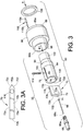
Fig. 2 is an enlarged view of the circled region ofFig. 1A ; -
Fig. 3 is an exploded view of an electrode support assembly shown inFig. 2 ; -
Fig. 3A is a top plan view of a wear resistant member; -
Fig. 4 is a front end elevation of the spray gun ofFig. 1 ; and -
Fig. 5 is the section view ofFig. 2 rotated 90° about the X axis. - Although the exemplary embodiments are described in terms of a spray gun for spraying porcelain enamel powder coating materials, the embodiments are not limited to such material, and will find application in other spray coating systems using powders that may be organic or glass or other compositions. While the exemplary embodiment of a spray gun is illustrated herein as an automatic gun, and more particularly an automatic spray gun in a bar mount configuration, those skilled in the art will readily understand and appreciate that the embodiments may also be conveniently used with manual spray guns, as well as automatic guns with other mounting or support configurations, including but not limited to tube mount. The embodiments described herein relate to components associated at the spray end or outlet of the spray gun, such as the spray nozzle, an electrode assembly and so on. Therefore, the embodiments may readily be adapted to other spray gun configurations. The exemplary embodiments utilize ceramic as a wear resistant material for some parts that are exposed to flow of an abrasive powder coating material. But those skilled in the art will readily understand that ceramic is only one example of a wear resistant material that may be used for such parts. Other wear resistant materials may be used as needed, for example, borosilicate glass such as PYREX™ and hardened steels, such as steel having a Rockwell C hardness in the upper sixties or more.
- While various aspects and features and concepts are described and illustrated herein in the exemplary embodiments, these various aspects, features and concepts may be realized in many alternative embodiments. Still further, while various alternative embodiments as to the various aspects and features, such as alternative materials, structures, configurations, methods, devices and so on may be described herein, such descriptions are not intended to be a complete or exhaustive list of available alternative embodiments, whether presently known or later developed. Those skilled in the art may readily adopt one or more of the aspects, concepts or features, even if such embodiments are not expressly disclosed herein. Additionally, even though some features, concepts or aspects may be described herein as being a preferred arrangement or method, such description is not intended to suggest that such feature is required or necessary unless expressly so stated. Still further, exemplary or representative values and ranges may be included to assist in understanding the present embodiments however, such values and ranges are not to be construed in a limiting sense and are intended to be critical values or ranges only if so expressly stated. Additionally, even though some features and aspects and combinations thereof may be described or illustrated herein as having a specific form, fit, function, arrangement or method, such description is not intended to suggest that such descriptions or illustrated arrangements are required or necessary unless so expressly stated. Those skilled in the art will readily appreciate additional and alternative form, function, arrangement or methods that are either known or later developed as substitute or alternatives for the embodiments described herein.
- By way of introduction, this disclosure presents a number of concepts as embodied in the examples illustrated in the drawings and explained in the specification. One such concept is the use of a powder flow path that directs powder flow along an axis into a spray nozzle assembly, and an electrode assembly is provided that positions an electrode tip within an interior flow volume or path of the spray nozzle body. In one embodiment, the electrode assembly is preferably in-line with the powder flow axis into the spray nozzle assembly. The in-line configuration of the electrode assembly reduces direct impact of abrasive powder coating material on interior surfaces of the spray nozzle assembly. The in-line configuration of the electrode assembly facilitates use of a compliant member or sleeve that is made of an elastically compliant material, to position and support the electrode assembly at a desired location. Additional embodiments of this concept are presented herein.
- In other embodiments of the concept for an in-line configuration of the electrode assembly, a powder flow path may optionally extend along a single powder flow axis from an inlet end of a spray gun body into a spray nozzle at an outlet end of the spray gun body wherein the spray nozzle has a powder flow axis into the spray nozzle and an electrode assembly that is in-line with the powder flow axis into the spray nozzle. In a more preferred embodiment, the powder flow axis into the spray nozzle is collinear with the powder flow axis through the spray gun body. This same axis powder flow path through the spray gun body and into the spray nozzle reduces dead zones within the spray nozzle to facilitate purge and cleaning operations for the spray gun. Additional embodiments of this concept are presented herein.
- Another inventive concept is a support structure for an electrode. In one embodiment, a wear resistant electrode support member is disposed and supported within a compliant sleeve. The compliant sleeve provides a cushioned support for the wear resistant member. Additional embodiments of this concept are presented herein.
- Another inventive concept is the provision of a sleeve that is made of compliant material and supports an electrode assembly. An example of a compliant material is an elastic material such as polyurethane, but many other plastic and polymer based elastic materials may be used as a compliant material for the sleeve. The compliant sleeve provides a cushioned holder for the electrode assembly, and also optionally provides a compliant and cushioned connection for a glass powder tube end. Additional embodiments of this concept are presented herein.
- Another concept is embodied in a spray nozzle assembly that incorporates a compliant member, such as a sleeve, for example, and a wear resistant electrode support member. The spray nozzle may include a nozzle body also made of ceramic or other wear resistant material. Additional embodiments of this concept are presented herein.
- With reference to
Figs. 1 and 1A and2 , an embodiment of aspray gun 10 is illustrated. Thespray gun 10 may be used for spraying powder coating material on objects or workpieces, and even though many different powder materials may be used, various features of thespray gun 10 are particularly well suited for spraying abrasive powders such as, for example, porcelain enamel powder. Generally, thespray gun 10 shares many common design aspects with a commercially available Encore® model spray gun available from Nordson Corporation, Westlake, Ohio. Therefore, many of the details of thespray gun 10 and the operations and design of the components are well known and do not need to be described. The present embodiments primarily relate to theforward end 12 of thespray gun 10, in particular thespray nozzle 14 and related components. The commercially available Encore® model spray gun was originally designed for spraying organic powder coating materials. Those skilled in the art will therefore readily appreciate that the present disclosure provides the ability to configure an Encore® model gun for spraying organic powders and also, with a few component substitutions, to configure the spray gun to spray abrasive powders such as porcelain enamel powder. Although the embodiments herein utilize much of the design of the Encore® model spray gun, such is not required, and the embodiments may be used with many other spray gun designs as needed. - The
spray gun 10 includes ahousing 16 which may be provided as multiple sections held together such as by using threaded connections and compression joints. Thehousing 16 thus may include afront gun body 18 that houses and supports a high voltage source such as amultiplier 20. Themultiplier 20 generates a high voltage in order to apply electrostatic charge to the powder coating material as is well known. Thehousing 16 may further include arear gun body 22 that is attached to thefront gun body 18 by any convenient means such as screws (not shown) for example. Thehousing 16 may further include thespray nozzle 14 and anozzle nut 24. Thenozzle nut 24 has a threaded connection 26 (Fig. 2 ) onto a threaded forward end of thefront gun body 18, and thenozzle nut 24 also includes aforward lip 28 that engages a flange 30 on thespray nozzle 14. - When the
nozzle nut 24 is tightened onto thefront gun body 18, thespray nozzle 14 is pulled up tight against an electrode assembly 32 (Fig. 3 ). Theelectrode assembly 32 may be considered as being part of a front end assembly 34 (Fig. 1 ) that we also refer to herein as aspray nozzle assembly 34 for thespray gun 10. Theelectrode assembly 32 provides part of a powder flow path P that extends from apowder inlet end 36 at the back end of thespray gun 10 to a spray orifice oroutlet 38 that is formed in thespray nozzle 14. The spray orifice oroutlet 38 may be realized in the form of a slot, opening or other geometry that produces a desired spray pattern from thespray nozzle assembly 34. In the exemplary embodiment, the powder flow path P may be centered along a longitudinal axis X of thespray gun 10, and is a straight line flow path within apowder tube 40 and through thegun body spray nozzle assembly 34, although straight line powder flow from thepowder inlet end 36 to thespray orifice 38 is not required. This flow path P allows for a smooth wall assembly that minimizes or can eliminate entrapment areas in the powder flow path, thus facilitating fast color change and purging operations. Theelectrode assembly 32 provides a forward portion P1 (Fig. 2 ) of the powder flow path P as further described below. Alternatively, the P1 path need not be collinear with the flow path P that is upstream of theelectrode assembly 32. The longitudinal axis X may be the center longitudinal axis of thepowder tube 40. - In contrast with the Encore® model spray gun that is configured for organic powder, the
spray gun 10 embodiment differs in the design of thefront end assembly 34 in order to accommodate an abrasive powder coating material. In addition, thespray gun 10 uses aglass powder tube 40, for example made of PYREX™, as is well known in the art of spraying abrasive powder coating materials like porcelain enamel. Alternatively, thepowder tube 40 may comprise an abrasion resistant material other than glass as needed. The balance of parts of thespray gun 10 may be but need not be the same as the Encore® model spray gun. - A
bulkhead 42 is attached by screws (not shown), compression fit or other convenient means to the back end of thefront gun body 18 so as to cover the rearward open end of thefront gun body 18, thereby also enclosing themultiplier 20. Thebulkhead 42 includes apowder tube opening 44 which allows thepowder tube 40 to be pushed through thefront gun body 18 to thefront end assembly 34. Thebulkhead 42 also provides acable opening 46 through whichelectrical wires 48 can pass to themultiplier 20 so as to provide input power to themultiplier 20 from anelectrical connector 50 that is connectable to a power source (not shown). - A spray gun
bar mount assembly 52 may be installed on therear gun body 22. Thebar mount assembly 52 is used to releasably support thespray gun 10 on a bar or other support that is used to position thespray gun 10 for a coating operation, usually performed in a spray booth, as is well known. Thebar mount assembly 52 may include abar mount adapter 54 that attaches to therear gun body 22. Thebar mount adapter 54 may comprise metal and provides an electrical ground for themultiplier 20. Although the exemplary embodiment illustrates a bar mount configuration for the spray gun, the embodiments may also be used with tube mount configurations in which the housing typically is longer than the bar mount configuration, with the spray gun installed on a gun mover such as an oscillator, reciprocator, and so on as is well known. - The
glass powder tube 40, when fully inserted into thespray gun 10, extends out the back of thespray gun 10 through anopening 56 in thebar mount adapter 54. A powdersupply hose connector 58 may be installed in anopening 56 in thebar mount adapter 54. The powdersupply hose connector 58 provides anipple 60 which receives a powder supply hose (not shown) that is connectable to a supply (not shown) of powder coating material. Aseal 62, for example a common o-ring seal, may be used to provide a seal and soft interface between theglass powder tube 40 and thehose connector 58. - With reference to
Figs. 2 ,3 and4 , thefront end assembly 34 provides structure for supporting theelectrode assembly 32 and providing a forward portion P1 of the powder flow path P. The forward portion P1 of the powder flow path extends from theoutlet end 40a of thepowder tube 40 through thespray orifice 38. This forward portion P1 of the powder flow path is defined in part by an interior volume of anannular sleeve 64. Theannular sleeve 64 is realized in the form of acompliant sleeve 64. Because thecompliant sleeve 64 comprises a compliant elastic material, for example plastic, thecompliant sleeve 64 will tend to abrade and wear due to exposure to the powder coating material, particularly abrasive powder coating material such as glass powder. We therefore can consider the compliant sleeve to be a "wear sleeve" or wear component. By "wear sleeve" then is meant herein that as the annular sleeve becomes exposed to the abrasive powder during coating operations, over time thesleeve 64 will become worn and need to be replaced. But there are benefits from use of a wear sleeve that make the use of a readily replaceable item beneficial, as will be apparent from further discussion hereinbelow. - The
electrode assembly 32 includes in part anelectrode 66 that may be supported by anelectrode holder 68. Theelectrode holder 68 may be securely installed in a wear resistantelectrode support member 70 so that anelectrode discharge tip 66a is disposed in an appropriate position with respect to the powder flow through thespray nozzle assembly 34 in order to apply an electrostatic charge to the powder that flows through thespray nozzle 14. Theelectrode holder 68 may be made of any suitable material such as nylon. In the exemplary embodiments, theelectrode discharge tip 66a may be disposed within the interior volume of thespray nozzle 14, preferably near thespray orifice 38. However, theelectrode discharge tip 66a may be positioned elsewhere as needed for a particular spray gun. It is further preferred that theelectrode 66 be positioned in-line with the powder flow path P1 of the powder as the powder leaves thepowder tube 40 and passes into theelectrode assembly 32 and thespray nozzle 14. It is preferred but not required that theelectrode 66 be centered on the X axis which may also be the center axis of thepowder tube 40 and the powder flow path P, P1. This in-line orientation is made available by the use of theannular sleeve 64 that supports theelectrode holder 68 in-line with the directional flow path P1 of the powder flow. This allows a powder flow path P1 from the powdertube outlet end 40a, through theelectrode assembly 32 and through thespray nozzle 14 and thespray orifice 38 along a single directional axis, which directional axis in this exemplary embodiment preferably is collinear with the longitudinal axis X of thepowder tube 40 along which the powder flows end to end through thespray gun 10. - With particular reference to
Figs. 2 ,3 ,3A and4 , the in-line electrode orientation exposes the wearresistant member 70 to the abrasive powder flow. In one embodiment, the wearresistant member 70 is provided in the form of a thin, six sided plate-like body 72, which may also be referred to in the art as aspider 72. The term spider in the art commonly refers to a structure that is disposed in a tubular member and that supports an electrode in a powder flow path through the tubular member, but presents a reduced obstruction to the powder flow by supporting the electrode holder with legs or extensions out to the surrounding wall of the tubular member. Thespider 72 includes a first blind bore 74 (Fig. 2 ) that is threaded and receives a threadedportion 68a of theelectrode holder 68. Thespider 72 includes twomajor sides 72a and fourminor sides 72b, of which only twominor sides 72c contact powder directly. Theminor sides 72b need only provide sufficient width to thespider 72 to accommodate and secure the diameter of the electrode holder threadedportion 68a. Themajor sides 72a are sized so as to be slideably received inrespective slots 75, 76 (Fig. 3 ) formed in theannular sleeve 64. The backward or upstream facingminor side 72b will be exposed to the most direct impact from the abrasive powder and, therefore, may have taperedsides 72c to reduce direct impact wear. By supporting thespider 72 with themajor sides 72a parallel to the general powder flow path direction P1, most of the surface area of thespider 72 will not be exposed to direct impact by the powder. We refer to the "general" powder flow path direction because within thespray nozzle body 80 and thewear sleeve 64 the powder flow is not simply along a single directional axis, but does move through thespray nozzle assembly 34 from an entrance end (124) to thespray outlet orifice 38 in a generally consistent direction centered about the axis X. As best illustrated inFig. 5 , thethin spider 72 also allows forsubstantial space 78 within thesleeve 64 for the powder to flow through theannular sleeve 64 and around thespider 72. - The wear
resistant member 70 preferably is made of ceramic material, as is thespray nozzle body 80, or at least the surfaces that are exposed to the abrasive powder flow are made
of a wear resistant or ceramic material. Other wear resistant materials may be used, but for the art of spraying porcelain enamel powders, ceramic materials are commonly used. - The annular sleeve or wear
sleeve 64 as noted above preferably is made of a compliant elastic material. We accomplish this by making thecompliant sleeve 64 out of a plastic or other suitable compliant and preferably elastic material. Even though thewear sleeve 64 is exposed to the abrasive powder, much of the sleeve wall structure 82 (Fig. 3 ) is cylindrical and parallel with the powder flow path PI, thereby reducing direct impact of the abrasive powder against the interior surfaces of thecompliant sleeve 64. - By having the
compliant sleeve 64 that supports theelectrode 66 made of an elastic material, we use less of the wear resistant material, such as ceramic, in the powder flow path, which is an expensive material compared to plastic, for theelectrode assembly 32. The thin plate-like profile of thespider 72 also uses less ceramic material compared to the prior art which uses protective ceramic sleeves that surround the electrode. Although the wear sleeve may need replacement over time, the compliant wear sleeve is lower in cost as compared to a ceramic wear sleeve, is easily replaced and provides the cushioned mount for the expensive ceramic electrode support member and the glass powder tube. - The elastic material of the
compliant sleeve 64 also provides a soft cushioned support for theceramic spider 72. Theelastic sleeve 64 can thus absorb shock and protect the more fragileceramic spider 72 should impact occur such as dropping or knocking the spray gun, or other impacts to theelectrode assembly 32. - The combination of the
annular sleeve 64 made of compliant material and the wearresistant member 70 supported by theannular sleeve 64 thus provides a significant advance in the art by reducing the amount of ceramic needed for a spray nozzle assembly in a spray gun for abrasive powders. This combination benefits from the preferred but optional use of the in-line orientation of theelectrode assembly 32 in the powder flow path P1 through theannular sleeve 64 because theannular sleeve 64 is not exposed to direct or facing impact from the abrasive powder but rather is exposed to an indirect contact with the powder. Although thewear sleeve 64 over time will need to be replaced, this replacement is quick and simple. By simply removing thenozzle nut 24 and thespray nozzle body 80, the operator has direct access to thecompliant sleeve 64 which can easily be removed (as described below, thesleeve 64 is supported in the spray gun by a support sleeve which can also be removed for easier access to thewear sleeve 64.) Thespider 72 may also be quickly slid out of thesleeve 64 when thesleeve 64 is being replaced. - With reference to
Figs. 2 and3 , a forwarddistal end portion 18a of thefront gun body 18 includes a front recess orsocket 84. Anelectrode support assembly 85 includes anelectrode support sleeve 86 having afirst end portion 86a that fits into thefront recess 84 of thefront gun body 18 such that aradial shoulder 88 abuts thedistal end 18a of thefront gun body 18. Thecompliant sleeve 64 is disposed inside theelectrode support sleeve 86. Theelectrode support sleeve 86 includes aninterior stop shoulder 92 that abuts an exteriorradial shoulder 94 of thecompliant sleeve 64, thus axially positioning thesleeve 64 inside theelectrode support sleeve 86. As noted hereinabove, the wearresistant spider 72 is disposed inside thecompliant sleeve 64 via the upper andlower slots spider 72 is inserted into thecompliant sleeve 64 until the taperedminor sides 72c bottom on a complementary profiledshoulder 96 inside thecompliant sleeve 64. Theelectrode support sleeve 86 includes asecond end portion 86b that fits into acounterbore 80a of thespray nozzle body 80 such that thedistal end 86b of theelectrode support sleeve 86 abuts aninternal shoulder 90 formed by thecounterbore 80a. Theelectrode support sleeve 86 may be provided with an alignmentkey slot 98 that receives akey tab 100 provided on thecompliant sleeve 64. This assures that thecompliant sleeve 64 is inserted into theelectrode support sleeve 86 in the correct orientation so that electrical connection can be made to theelectrode 66 as described below. - The length of the
electrode support sleeve 86 and the length of thespider 72 may be selected such that when thenozzle nut 24 is tightened onto thefront gun body 18, such as with the threadedconnection 26, theinternal shoulder 90 of thespray nozzle body 80 abuts thedistal end 86b of theelectrode support sleeve 86. This results in thenozzle nut 24 compressively loading thespray nozzle body 80 and theelectrode support sleeve 86 against theforward end portion 18a of thefront gun body 18. This securely joins thespray nozzle assembly 34, including theelectrode assembly 32, to thefront gun body 18. - The front end or
spray nozzle assembly 34 thus comprises theelectrode support assembly 85 and thespray nozzle body 80 and is secured to thespray gun body 18 with thenozzle nut 24. These are the basic parts, along with theglass powder tube 40, that are used in place of the spray nozzle and electrode related components of the Encore® model organic powder spray gun configuration. Theelectrode assembly 32 comprises thecompliant sleeve 64, theelectrode 66 and thespider 72. Theelectrode support assembly 85 comprises theelectrode support sleeve 86, thecompliant sleeve 64, thespider 72 and theelectrode 66. From these assembly points of view, theelectrode 66 is a basic element, although there may be additional components that are used to support the electrode and to connect the electrode to a power source as described below. - The
electrode 66 is positioned in thespray nozzle assembly 34 such that preferably theelectrode discharge tip 66a is disposed near thespray orifice 38 of thespray nozzle 14. Electrical energy is supplied to theelectrode 66 from themultiplier 20. Theelectrode 66 may include acoiled end 102 at an end opposite theelectrode discharge tip 66a. Theelectrode support sleeve 86 may include an annular electricallyconductive electrode ring 106. A multiplieroutput contact pin 108 contacts the electricallyconductive electrode ring 106. The electricallyconductive electrode ring 106 contacts afirst lead 110a of a current limitingresistor 110 that is supported in afirst bore 112 in theelectrode support sleeve 86. Theresistor 110 has asecond lead 110b that contacts anelectrode contact spring 114. Theelectrode 66 is retained in theelectrode holder 68 that has a threaded connection with the threaded first blind bore 74 or other suitable mechanical connection technique. Theelectrode contact spring 114 is disposed in a second blind bore 116 that extends through a portion of thespider 72 and intersects with the first blind bore 74. This allows the electrode coiledend 102 to make electrical contact with theelectrode contact spring 114. In this manner, electrical energy from themultiplier 20 is conducted to theelectrode tip 66a via themultiplier output pin 108, theconductive electrode ring 106, theresistor 110, theelectrode contact spring 114 and the electrode coiledend 102, to charge the powder coating material electrostatically as it flows through thespray nozzle 14 and out thespray orifice 38. - The
electrode support sleeve 86 includes a second bore 118 that intersects with a reduced diameter portion of thefirst bore 112. Theelectrode contact spring 114 extends up through the second blind bore 116 in thespider 72, and through ahole 120 in thecompliant sleeve 64. Thehole 120 aligns with the second bore 118 in theelectrode support sleeve 86 so that theelectrode contact spring 114 extends through thehole 120 and into the second bore 118. Thesecond lead 110b of theresistor 110 extends into the second bore 118 so as to make contact with theelectrode contact spring 114. - In an exemplary method of the
electrode assembly 32 into thespray nozzle assembly 34. Prior to installing theelectrode assembly 32, theconductive electrode ring 106, theresistor 110 and theelectrode support sleeve 86 are installed at the front end of the spray gun. Next, thespider 72 is pressed into thecompliant sleeve 64 until the taperedback end 72c seats in thecomplementary shoulder 96, which aligns the second blind bore 116 with thehole 120 in thecompliant sleeve 64. Thespring 114 is inserted down into the secondblind bore 116 until it bottoms. Separately, theelectrode 66 is installed into theelectrode holder 68. In its relaxed state, theelectrode contact spring 114 extends up out of the secondblind bore 116 and thehole 120. Thespring 114 can be axially compressed until an upper end 114a is at least flush with the upper (as viewed inFig. 2 ) surface of thecompliant sleeve 64. Thecompliant sleeve 64 is inserted into the electrode support sleeve 86 (with alignment of thekey slot 98 and the key tab 100) so that thehole 120 is blocked initially by the interior wall of theelectrode support sleeve 86 and theelectrode contact spring 114 is trapped in the secondblind bore 116. When thecompliant sleeve 64 has been fully inserted into theelectrode support sleeve 86 such that the exteriorradial shoulder 94 of thecompliant sleeve 64 abuts theinterior stop shoulder 92 of theelectrode support sleeve 86, thehole 120 aligns with the second bore 118 of theelectrode support sleeve 86 and theelectrode contact spring 114 axially relaxes so as to snap up into the second bore 118 to make contact with thesecond lead 110b of the previously installedresistor 110. - The
compliant sleeve 64 may further include a rearward cylindricalopen end 122 that snugly and compliantly fits over theoutlet end 40a of theglass powder tube 40. Theglass powder tube 40 can be inserted through therear gun body 22 and pushed through thefront gun body 18 until it seats in theopen end 122 of thecompliant sleeve 64. Thecompliant sleeve 64 may be provided with aninternal shoulder 124 against which theglass tube end 40a seats when fully inserted. Thisshoulder 124 may be considered the entrance end of thespray nozzle assembly 34 as powder exits theglass powder tube 40. It is preferred although not required that thecompliant sleeve 64 be elastically compliant so as to form a sealed interface with theglass powder tube 40. - It should be noted that the specific details of the exemplary embodiments are not exclusive or required. The components may be realized in alternative form, fit and function as needed for a particular application. By way of an example, the
spider 72 andelectrode holder 68 could be made as a unitary structure to support theelectrode 66 within thewear sleeve 64. Many different electrical arrangements can be used to couple the electrical energy from themultiplier 20 to theelectrode 66. And alternative structures can be used to hold thefront end assembly 34 components together and with thefront gun body 18. So, the exemplary embodiments are not to be construed as limited to the specific structures and arrangements illustrated and described herein. - As noted hereinabove, the
compliant sleeve 64 preferably comprises elastic material such as a plastic. The plastic material may be any suitable polymer, for example, polyurethane. It is desirable for many applications that the compliant sleeve plastic material have the characteristic of being resilient so that thecompliant sleeve 64 may be used to form optional sealed interfaces with theglass powder tube 40 and thespray nozzle body 80. However, many alternative techniques are available to provide these sealed interfaces. Independently, it is also preferred but not required that the wear sleeve be elastic so as to provide a cushioned support for thespider 72, whether or not thewear sleeve 64 is used for sealing interfaces. - By elastic we mean that the plastic material has sufficient elasticity to allow the
compliant sleeve 64 to be compliant or conform with theglass powder tube 40. For example, in the embodiment ofFig. 2 , thecompliant sleeve 64inner end 122 can stretch out to allow the glasspowder tube end 40a to be inserted and to form a sealed interface. Whether some degree of plastic deformation also occurs at this interface is not a major concern because over time thewear sleeve 64 is replaced. But the compliant nature of thesleeve 64 allows a sealed interface with the glasspowder tube end 40a without using additional seals such as o-rings. Alternatively, a less elastic plastic material may be used for thewear sleeve 64 along with alternative methods to seal the interface with the glasspowder tube end 40a, even without inserting the glasspowder tube end 40a into a portion of thewear sleeve 64. - The use of plastic material for the
compliant sleeve 64, and preferably an elastically compliant material, allows for a face seal type sealed interface between thesleeve 64 forwardopen end 64a and the spray nozzle bodyinternal shoulder 90. The length of thesleeve 64 may be selected so that when thesleeve 64 is fully inserted into theelectrode support sleeve 86, a small portion, perhaps a few millimeters, extends outside thesecond end portion 86b of theelectrode support sleeve 86. When thenozzle nut 24 is tightened onto thefront gun body 18, theinternal shoulder 90 axially compresses against theopen end 64a of thesleeve 64 to form a sealed interface. Alternatively, other seal arrangements may be used to form the sealed interface as are well known in the art. The compliant nature of thesleeve 64 thus may be optionally used for various purposes, alone or in various combinations, including but not limited to forming a sealed interface with theglass powder tube 40, forming a sealed interface with thespray nozzle body 80, and providing a cushioned support for the wearresistant member 70.
The invention has been described with reference to the exemplary embodiments. Modifications and alterations will occur to others upon a reading and understanding of this specification and drawings.
Claims (13)
- A spray gun for powder coating material, comprising;
a housing (16) comprising a spray nozzle body (80), said spray nozzle body (80) comprising a powder inlet and a spray orifice (38);
a powder tube (40) having an outlet end (40a) through which powder coating material flows into said spray nozzle body (80) during a coating operation through said powder inlet along an axis, and
an electrode (66) disposed within said housing (16), characterized in that the spray gun comprises:a wear resistant member (70) that supports said electrode (66), said wear resistant member comprising a wear resistant material; anda compliant sleeve (64) that supports said wear resistant member (70) in line with said axis, said compliant sleeve comprising slots (75, 76) that receive the wear resistant member (70), said compliant sleeve (64) comprising an elastic material that is more compliant than the wear resistant material. - The spray gun of claim 1 wherein said spray nozzle body (80) comprises ceramic.
- The spray gun of claim 1 wherein said wear resistant material comprises ceramic.
- The spray gun of claim 1 wherein said powder tube (40) is a glass tube having the outlet end (40a) through which powder coating material flows into said spray nozzle body (80) through said powder inlet.
- The spray gun of claim 4 wherein said compliant sleeve (64) comprises plastic and is disposed between said glass tube outlet end (40a) and said spray orifice (38), said wear resistant member (70) comprising ceramic and being disposed within said compliant sleeve (64).
- The spray gun of claim 4 wherein said compliant sleeve (64) comprises a compliant material and comprises a first open end (122) that forms a seal with said glass tube outlet end (40a).
- The spray gun of claim 6 wherein said compliant sleeve (64) comprises a second open end (64a) that forms a seal against a surface (90) of said spray nozzle body (80).
- The spray gun of claim 4 wherein said glass powder tube (40), said compliant sleeve (64) and said spray nozzle body (80) define a powder flow path (P) along said axis with said electrode (66) being disposed in line with said axis.
- The spray gun of claim 1 wherein said powder tube (40) is a glass tube and said compliant sleeve (64) is disposed between said glass tube (40) and said spray nozzle body (80), wherein said glass tube (40), said compliant sleeve (64) and said spray nozzle body (80) define a powder flow path (P) along said axis with said electrode (66) being supported in line with said axis.
- The spray gun of claim 1 wherein said compliant sleeve (64) comprises a compliant material and comprises a first open end (122) that forms a sealed interface with said powder tube (40).
- The spray gun of claim 10 wherein said powder tube (40) is a glass tube.
- The spray gun of claim 1 wherein said compliant sleeve (64) comprises a compliant material and forms a sealed interface against a surface (90) of said spray nozzle body (80).
- The spray gun of claim 12 wherein said sealed interface is a compressed face seal between said compliant sleeve (64) and said spray nozzle body (80).
Applications Claiming Priority (2)
| Application Number | Priority Date | Filing Date | Title |
|---|---|---|---|
| US201261623219P | 2012-04-12 | 2012-04-12 | |
| PCT/US2013/029086 WO2013154696A1 (en) | 2012-04-12 | 2013-03-05 | Powder spray gun comprising a wear resistant electrode support |
Publications (2)
| Publication Number | Publication Date |
|---|---|
| EP2836308A1 EP2836308A1 (en) | 2015-02-18 |
| EP2836308B1 true EP2836308B1 (en) | 2019-07-17 |
Family
ID=48087681
Family Applications (1)
| Application Number | Title | Priority Date | Filing Date |
|---|---|---|---|
| EP13715784.8A Revoked EP2836308B1 (en) | 2012-04-12 | 2013-03-05 | Powder spray gun comprising a wear resistant electrode support |
Country Status (5)
| Country | Link |
|---|---|
| US (2) | US10150123B2 (en) |
| EP (1) | EP2836308B1 (en) |
| JP (1) | JP6242854B2 (en) |
| CN (1) | CN104245147B (en) |
| WO (1) | WO2013154696A1 (en) |
Families Citing this family (6)
| Publication number | Priority date | Publication date | Assignee | Title |
|---|---|---|---|---|
| CN104245147B (en) * | 2012-04-12 | 2018-11-06 | 诺信公司 | Powder spray gun including wear-resistant electrode support |
| JP2016159249A (en) * | 2015-03-03 | 2016-09-05 | 旭サナック株式会社 | Gun cover for powder coating gun |
| CN107262320B (en) * | 2017-06-26 | 2023-08-29 | 中信戴卡股份有限公司 | Automatic powder cleaning system for mixed-wire type hub bolt hole and combined powder cleaning gun |
| USD913418S1 (en) * | 2018-07-10 | 2021-03-16 | Nordson Corporation | Powder spray gun component |
| BE1026693B1 (en) * | 2018-10-09 | 2020-05-11 | Detandt Nathalie | Powder feed injector |
| CN116571371B (en) * | 2023-07-06 | 2023-09-08 | 中国空气动力研究与发展中心高速空气动力研究所 | Ejector device combining distributed two-dimensional spray pipe and traditional circumferential seam |
Citations (9)
| Publication number | Priority date | Publication date | Assignee | Title |
|---|---|---|---|---|
| EP0236794A2 (en) | 1986-03-13 | 1987-09-16 | ITW Gema AG | Electrostatic spray device for coating powder |
| EP0383030A1 (en) | 1989-02-14 | 1990-08-22 | ITW Gema AG | Sprayer for electrostatic spray-coating |
| EP0599498A1 (en) | 1992-11-23 | 1994-06-01 | Nordson Corporation | Powder spray nozzle |
| EP0756898A1 (en) | 1995-01-30 | 1997-02-05 | ABB Industry K.K. | Spray gun type electrostatic painting apparatus |
| EP1084759A2 (en) | 1999-09-16 | 2001-03-21 | Nordson Corporation | Powder spray gun |
| DE29924481U1 (en) | 1998-08-22 | 2003-06-12 | Itw Gema Ag, St. Gallen | Spray coating arrangement for coating powder has contact arrangement on rearward facing fitting between two tube sections of powder channel least 1.5 cm. from rear end of rear tube section |
| EP1614479A1 (en) | 2003-03-27 | 2006-01-11 | Asahi Sunac Corporation | Electrostatic coating spray gun |
| DE102004055106A1 (en) | 2004-11-15 | 2006-05-24 | P + S Pulverbeschichtungs- Und Staubfilteranlagen Gmbh | Delivery unit for an atomized material such as powder or fluid paints to a workpiece coating device has material air stream lead that widens downstream |
| EP1752224A2 (en) | 2005-08-12 | 2007-02-14 | J. Wagner AG | Electrode holder for a powder spray coating apparatus |
Family Cites Families (31)
| Publication number | Priority date | Publication date | Assignee | Title |
|---|---|---|---|---|
| US99018A (en) | 1870-01-18 | Improvement in rubber hose | ||
| US3131867A (en) * | 1963-05-31 | 1964-05-05 | J C Nees And Betty Nees | Rotary pop-up sprinkler |
| US3793049A (en) * | 1969-06-16 | 1974-02-19 | R Probst | Electrostatic coating method |
| USD255145S (en) | 1976-10-21 | 1980-05-27 | Nederman Bill P P | Connection fitting for tubular conduits |
| USD267506S (en) | 1980-09-22 | 1983-01-04 | Evans Charles D | Quick connect coupling |
| US4530467A (en) * | 1983-02-09 | 1985-07-23 | Bueno Humberto E | Adjustable valve for faucet or shower head |
| DE3608415A1 (en) * | 1986-03-13 | 1987-09-24 | Gema Ransburg Ag | ELECTROSTATIC SPRAYING DEVICE FOR COATING POWDER |
| USD311573S (en) | 1986-05-27 | 1990-10-23 | Lewis Will A | Transistion pipe adapter |
| USD310556S (en) | 1987-06-08 | 1990-09-11 | Russell Industries, Inc. | Flexible hose clamp cover |
| JPH0673697B2 (en) * | 1987-10-24 | 1994-09-21 | 株式会社共立合金製作所 | Nozzle for scale removal |
| US5344082A (en) * | 1992-10-05 | 1994-09-06 | Nordson Corporation | Tribo-electric powder spray gun |
| USD364449S (en) | 1994-09-28 | 1995-11-21 | Ellenberger James P | Welding outlet |
| US6328224B1 (en) * | 1997-02-05 | 2001-12-11 | Illinois Tool Works Inc. | Replaceable liner for powder coating apparatus |
| US5853126A (en) * | 1997-02-05 | 1998-12-29 | Illinois Tool Works, Inc. | Quick disconnect for powder coating apparatus |
| USD407802S (en) | 1997-10-28 | 1999-04-06 | Hatfield J Paul | Pipe adaptor fitting |
| DE19838278A1 (en) * | 1998-08-22 | 2000-02-24 | Itw Gema Ag | Spray coating arrangement for coating powder has contact arrangement on rearward facing fitting between two tube sections of powder channel least 1.5 cm. from rear end of rear tube section |
| USD452299S1 (en) | 2000-04-05 | 2001-12-18 | American Standard International Inc. | Threaded collet assembly |
| US6676029B2 (en) * | 2002-03-01 | 2004-01-13 | Husky Corporation | Stream straightener for fluid flowing and dispensing nozzle |
| USD480454S1 (en) | 2002-12-05 | 2003-10-07 | Pipelife Jet Stream, Inc. | Exiting spiral spline female pipe coupling |
| CN1305593C (en) * | 2002-12-25 | 2007-03-21 | 株式会社共立合金制作所 | Descaling nozzle |
| US7128277B2 (en) * | 2003-07-29 | 2006-10-31 | Illinois Tool Works Inc. | Powder bell with secondary charging electrode |
| US20050173556A1 (en) * | 2004-02-09 | 2005-08-11 | Kui-Chiu Kwok | Coating dispensing nozzle |
| DE102005017931A1 (en) * | 2005-04-18 | 2006-10-19 | Itw Gema Ag | Powder spray coating gun and gun body for this purpose |
| USD546865S1 (en) | 2005-07-11 | 2007-07-17 | Rietveld Floyd L | Camera support handle |
| JP5047569B2 (en) * | 2005-09-30 | 2012-10-10 | 新東工業株式会社 | Powder flow rate measuring device |
| USD546665S1 (en) | 2005-10-14 | 2007-07-17 | Terry Don Medlin | Fracturing sleeve |
| USD591407S1 (en) | 2008-07-08 | 2009-04-28 | Ipex Inc. | Pipe having a spigot end and a bell end |
| USD631542S1 (en) | 2008-12-12 | 2011-01-25 | Mark L. Anderson | Port |
| DE102009053601A1 (en) * | 2009-11-17 | 2011-05-19 | Dürr Systems GmbH | Supply hose for a paint shop |
| USD676943S1 (en) | 2012-01-11 | 2013-02-26 | Bill Kluss | Pipe end cap |
| CN104245147B (en) * | 2012-04-12 | 2018-11-06 | 诺信公司 | Powder spray gun including wear-resistant electrode support |
-
2013
- 2013-03-05 CN CN201380019734.8A patent/CN104245147B/en active Active
- 2013-03-05 EP EP13715784.8A patent/EP2836308B1/en not_active Revoked
- 2013-03-05 US US14/390,151 patent/US10150123B2/en active Active
- 2013-03-05 WO PCT/US2013/029086 patent/WO2013154696A1/en not_active Ceased
- 2013-03-05 JP JP2015505716A patent/JP6242854B2/en active Active
-
2018
- 2018-11-07 US US16/183,626 patent/US11925952B2/en active Active
Patent Citations (9)
| Publication number | Priority date | Publication date | Assignee | Title |
|---|---|---|---|---|
| EP0236794A2 (en) | 1986-03-13 | 1987-09-16 | ITW Gema AG | Electrostatic spray device for coating powder |
| EP0383030A1 (en) | 1989-02-14 | 1990-08-22 | ITW Gema AG | Sprayer for electrostatic spray-coating |
| EP0599498A1 (en) | 1992-11-23 | 1994-06-01 | Nordson Corporation | Powder spray nozzle |
| EP0756898A1 (en) | 1995-01-30 | 1997-02-05 | ABB Industry K.K. | Spray gun type electrostatic painting apparatus |
| DE29924481U1 (en) | 1998-08-22 | 2003-06-12 | Itw Gema Ag, St. Gallen | Spray coating arrangement for coating powder has contact arrangement on rearward facing fitting between two tube sections of powder channel least 1.5 cm. from rear end of rear tube section |
| EP1084759A2 (en) | 1999-09-16 | 2001-03-21 | Nordson Corporation | Powder spray gun |
| EP1614479A1 (en) | 2003-03-27 | 2006-01-11 | Asahi Sunac Corporation | Electrostatic coating spray gun |
| DE102004055106A1 (en) | 2004-11-15 | 2006-05-24 | P + S Pulverbeschichtungs- Und Staubfilteranlagen Gmbh | Delivery unit for an atomized material such as powder or fluid paints to a workpiece coating device has material air stream lead that widens downstream |
| EP1752224A2 (en) | 2005-08-12 | 2007-02-14 | J. Wagner AG | Electrode holder for a powder spray coating apparatus |
Also Published As
| Publication number | Publication date |
|---|---|
| US20150115073A1 (en) | 2015-04-30 |
| EP2836308A1 (en) | 2015-02-18 |
| US20190076859A1 (en) | 2019-03-14 |
| CN104245147B (en) | 2018-11-06 |
| US10150123B2 (en) | 2018-12-11 |
| CN104245147A (en) | 2014-12-24 |
| JP6242854B2 (en) | 2017-12-06 |
| WO2013154696A1 (en) | 2013-10-17 |
| JP2015517903A (en) | 2015-06-25 |
| US11925952B2 (en) | 2024-03-12 |
Similar Documents
| Publication | Publication Date | Title |
|---|---|---|
| US11925952B2 (en) | Powder spray gun comprising a wear resistant electrode support | |
| EP1084759B1 (en) | Powder spray gun | |
| EP0729791B1 (en) | Electrostatic coating system including improved spray gun for conductive paints | |
| JP5213700B2 (en) | Replaceable plasma nozzle interface and method of forming the same, and replaceable nozzle | |
| US3583632A (en) | Electrostatic spray coating apparatus | |
| KR200471644Y1 (en) | A module for attachment to a tool comprising a first fractional module and a second fractional module | |
| FR2567046A1 (en) | ELECTROSTATIC SPRAY APPARATUS TO BE MOUNTED ON ROBOT | |
| TW201941833A (en) | Spray gun and components for spraying paints and other coatings | |
| JPH0349200B2 (en) | ||
| JPH0532106B2 (en) | ||
| JP5189248B2 (en) | Thermal spray equipment | |
| RU2644903C2 (en) | Spray tip assembly for electrostatic spray gun | |
| CN104364017A (en) | Air flow switch for an electrostatic tool | |
| US20050023374A1 (en) | Powder spray gun | |
| KR20210147014A (en) | Mounting of external charging probe on electrostatic spray gun | |
| EP0611603B1 (en) | Electrostatic powder spray gun | |
| KR20210069002A (en) | Electrostatic rotary projector for coating product and spraying installation comprising such a projector | |
| US20030080220A1 (en) | Powder spray gun with inline angle spray nozzle | |
| EP1817112B1 (en) | Electrostatic spray nozzle system | |
| CA2404757C (en) | Spray coating device | |
| EP0745431B1 (en) | Spray gun with anti-back-ionization probe | |
| US9700906B2 (en) | Spray coating device for coating material | |
| US10239072B2 (en) | Energy dissipation unit for high voltage charged paint system | |
| JP3863481B2 (en) | Method and apparatus for electrostatic coating by external charging | |
| GB2354723A (en) | Electrostatic spray gun |
Legal Events
| Date | Code | Title | Description |
|---|---|---|---|
| PUAI | Public reference made under article 153(3) epc to a published international application that has entered the european phase |
Free format text: ORIGINAL CODE: 0009012 |
|
| 17P | Request for examination filed |
Effective date: 20141105 |
|
| AK | Designated contracting states |
Kind code of ref document: A1 Designated state(s): AL AT BE BG CH CY CZ DE DK EE ES FI FR GB GR HR HU IE IS IT LI LT LU LV MC MK MT NL NO PL PT RO RS SE SI SK SM TR |
|
| AX | Request for extension of the european patent |
Extension state: BA ME |
|
| DAX | Request for extension of the european patent (deleted) | ||
| STAA | Information on the status of an ep patent application or granted ep patent |
Free format text: STATUS: EXAMINATION IS IN PROGRESS |
|
| 17Q | First examination report despatched |
Effective date: 20180409 |
|
| RIC1 | Information provided on ipc code assigned before grant |
Ipc: B05B 5/025 20060101ALI20181213BHEP Ipc: B05B 15/18 20180101ALI20181213BHEP Ipc: B05B 7/02 20060101ALN20181213BHEP Ipc: B05B 5/053 20060101ALI20181213BHEP Ipc: B05B 5/03 20060101AFI20181213BHEP |
|
| GRAP | Despatch of communication of intention to grant a patent |
Free format text: ORIGINAL CODE: EPIDOSNIGR1 |
|
| STAA | Information on the status of an ep patent application or granted ep patent |
Free format text: STATUS: GRANT OF PATENT IS INTENDED |
|
| INTG | Intention to grant announced |
Effective date: 20190204 |
|
| GRAS | Grant fee paid |
Free format text: ORIGINAL CODE: EPIDOSNIGR3 |
|
| GRAA | (expected) grant |
Free format text: ORIGINAL CODE: 0009210 |
|
| STAA | Information on the status of an ep patent application or granted ep patent |
Free format text: STATUS: THE PATENT HAS BEEN GRANTED |
|
| AK | Designated contracting states |
Kind code of ref document: B1 Designated state(s): AL AT BE BG CH CY CZ DE DK EE ES FI FR GB GR HR HU IE IS IT LI LT LU LV MC MK MT NL NO PL PT RO RS SE SI SK SM TR |
|
| REG | Reference to a national code |
Ref country code: GB Ref legal event code: FG4D |
|
| REG | Reference to a national code |
Ref country code: CH Ref legal event code: EP |
|
| REG | Reference to a national code |
Ref country code: IE Ref legal event code: FG4D |
|
| REG | Reference to a national code |
Ref country code: DE Ref legal event code: R096 Ref document number: 602013057876 Country of ref document: DE |
|
| REG | Reference to a national code |
Ref country code: AT Ref legal event code: REF Ref document number: 1155357 Country of ref document: AT Kind code of ref document: T Effective date: 20190815 |
|
| REG | Reference to a national code |
Ref country code: CH Ref legal event code: NV Representative=s name: ING. MARCO ZARDI C/O M. ZARDI AND CO. S.A., CH |
|
| REG | Reference to a national code |
Ref country code: NL Ref legal event code: MP Effective date: 20190717 |
|
| REG | Reference to a national code |
Ref country code: LT Ref legal event code: MG4D |
|
| REG | Reference to a national code |
Ref country code: AT Ref legal event code: MK05 Ref document number: 1155357 Country of ref document: AT Kind code of ref document: T Effective date: 20190717 |
|
| PG25 | Lapsed in a contracting state [announced via postgrant information from national office to epo] |
Ref country code: LT Free format text: LAPSE BECAUSE OF FAILURE TO SUBMIT A TRANSLATION OF THE DESCRIPTION OR TO PAY THE FEE WITHIN THE PRESCRIBED TIME-LIMIT Effective date: 20190717 Ref country code: HR Free format text: LAPSE BECAUSE OF FAILURE TO SUBMIT A TRANSLATION OF THE DESCRIPTION OR TO PAY THE FEE WITHIN THE PRESCRIBED TIME-LIMIT Effective date: 20190717 Ref country code: NL Free format text: LAPSE BECAUSE OF FAILURE TO SUBMIT A TRANSLATION OF THE DESCRIPTION OR TO PAY THE FEE WITHIN THE PRESCRIBED TIME-LIMIT Effective date: 20190717 Ref country code: PT Free format text: LAPSE BECAUSE OF FAILURE TO SUBMIT A TRANSLATION OF THE DESCRIPTION OR TO PAY THE FEE WITHIN THE PRESCRIBED TIME-LIMIT Effective date: 20191118 Ref country code: SE Free format text: LAPSE BECAUSE OF FAILURE TO SUBMIT A TRANSLATION OF THE DESCRIPTION OR TO PAY THE FEE WITHIN THE PRESCRIBED TIME-LIMIT Effective date: 20190717 Ref country code: AT Free format text: LAPSE BECAUSE OF FAILURE TO SUBMIT A TRANSLATION OF THE DESCRIPTION OR TO PAY THE FEE WITHIN THE PRESCRIBED TIME-LIMIT Effective date: 20190717 Ref country code: FI Free format text: LAPSE BECAUSE OF FAILURE TO SUBMIT A TRANSLATION OF THE DESCRIPTION OR TO PAY THE FEE WITHIN THE PRESCRIBED TIME-LIMIT Effective date: 20190717 Ref country code: NO Free format text: LAPSE BECAUSE OF FAILURE TO SUBMIT A TRANSLATION OF THE DESCRIPTION OR TO PAY THE FEE WITHIN THE PRESCRIBED TIME-LIMIT Effective date: 20191017 Ref country code: BG Free format text: LAPSE BECAUSE OF FAILURE TO SUBMIT A TRANSLATION OF THE DESCRIPTION OR TO PAY THE FEE WITHIN THE PRESCRIBED TIME-LIMIT Effective date: 20191017 |
|
| PG25 | Lapsed in a contracting state [announced via postgrant information from national office to epo] |
Ref country code: RS Free format text: LAPSE BECAUSE OF FAILURE TO SUBMIT A TRANSLATION OF THE DESCRIPTION OR TO PAY THE FEE WITHIN THE PRESCRIBED TIME-LIMIT Effective date: 20190717 Ref country code: IS Free format text: LAPSE BECAUSE OF FAILURE TO SUBMIT A TRANSLATION OF THE DESCRIPTION OR TO PAY THE FEE WITHIN THE PRESCRIBED TIME-LIMIT Effective date: 20191117 Ref country code: LV Free format text: LAPSE BECAUSE OF FAILURE TO SUBMIT A TRANSLATION OF THE DESCRIPTION OR TO PAY THE FEE WITHIN THE PRESCRIBED TIME-LIMIT Effective date: 20190717 Ref country code: GR Free format text: LAPSE BECAUSE OF FAILURE TO SUBMIT A TRANSLATION OF THE DESCRIPTION OR TO PAY THE FEE WITHIN THE PRESCRIBED TIME-LIMIT Effective date: 20191018 Ref country code: AL Free format text: LAPSE BECAUSE OF FAILURE TO SUBMIT A TRANSLATION OF THE DESCRIPTION OR TO PAY THE FEE WITHIN THE PRESCRIBED TIME-LIMIT Effective date: 20190717 Ref country code: ES Free format text: LAPSE BECAUSE OF FAILURE TO SUBMIT A TRANSLATION OF THE DESCRIPTION OR TO PAY THE FEE WITHIN THE PRESCRIBED TIME-LIMIT Effective date: 20190717 |
|
| PG25 | Lapsed in a contracting state [announced via postgrant information from national office to epo] |
Ref country code: TR Free format text: LAPSE BECAUSE OF FAILURE TO SUBMIT A TRANSLATION OF THE DESCRIPTION OR TO PAY THE FEE WITHIN THE PRESCRIBED TIME-LIMIT Effective date: 20190717 |
|
| REG | Reference to a national code |
Ref country code: DE Ref legal event code: R026 Ref document number: 602013057876 Country of ref document: DE |
|
| PLBI | Opposition filed |
Free format text: ORIGINAL CODE: 0009260 |
|
| PG25 | Lapsed in a contracting state [announced via postgrant information from national office to epo] |
Ref country code: DK Free format text: LAPSE BECAUSE OF FAILURE TO SUBMIT A TRANSLATION OF THE DESCRIPTION OR TO PAY THE FEE WITHIN THE PRESCRIBED TIME-LIMIT Effective date: 20190717 Ref country code: PL Free format text: LAPSE BECAUSE OF FAILURE TO SUBMIT A TRANSLATION OF THE DESCRIPTION OR TO PAY THE FEE WITHIN THE PRESCRIBED TIME-LIMIT Effective date: 20190717 Ref country code: IT Free format text: LAPSE BECAUSE OF FAILURE TO SUBMIT A TRANSLATION OF THE DESCRIPTION OR TO PAY THE FEE WITHIN THE PRESCRIBED TIME-LIMIT Effective date: 20190717 Ref country code: RO Free format text: LAPSE BECAUSE OF FAILURE TO SUBMIT A TRANSLATION OF THE DESCRIPTION OR TO PAY THE FEE WITHIN THE PRESCRIBED TIME-LIMIT Effective date: 20190717 Ref country code: EE Free format text: LAPSE BECAUSE OF FAILURE TO SUBMIT A TRANSLATION OF THE DESCRIPTION OR TO PAY THE FEE WITHIN THE PRESCRIBED TIME-LIMIT Effective date: 20190717 |
|
| PGFP | Annual fee paid to national office [announced via postgrant information from national office to epo] |
Ref country code: DE Payment date: 20200320 Year of fee payment: 8 |
|
| 26 | Opposition filed |
Opponent name: GEMA SWITZERLAND GMBH Effective date: 20200417 |
|
| PG25 | Lapsed in a contracting state [announced via postgrant information from national office to epo] |
Ref country code: IS Free format text: LAPSE BECAUSE OF FAILURE TO SUBMIT A TRANSLATION OF THE DESCRIPTION OR TO PAY THE FEE WITHIN THE PRESCRIBED TIME-LIMIT Effective date: 20200224 Ref country code: SM Free format text: LAPSE BECAUSE OF FAILURE TO SUBMIT A TRANSLATION OF THE DESCRIPTION OR TO PAY THE FEE WITHIN THE PRESCRIBED TIME-LIMIT Effective date: 20190717 Ref country code: CZ Free format text: LAPSE BECAUSE OF FAILURE TO SUBMIT A TRANSLATION OF THE DESCRIPTION OR TO PAY THE FEE WITHIN THE PRESCRIBED TIME-LIMIT Effective date: 20190717 Ref country code: SK Free format text: LAPSE BECAUSE OF FAILURE TO SUBMIT A TRANSLATION OF THE DESCRIPTION OR TO PAY THE FEE WITHIN THE PRESCRIBED TIME-LIMIT Effective date: 20190717 |
|
| PGFP | Annual fee paid to national office [announced via postgrant information from national office to epo] |
Ref country code: CH Payment date: 20200319 Year of fee payment: 8 |
|
| PLAX | Notice of opposition and request to file observation + time limit sent |
Free format text: ORIGINAL CODE: EPIDOSNOBS2 |
|
| PGFP | Annual fee paid to national office [announced via postgrant information from national office to epo] |
Ref country code: FR Payment date: 20200320 Year of fee payment: 8 |
|
| PLBB | Reply of patent proprietor to notice(s) of opposition received |
Free format text: ORIGINAL CODE: EPIDOSNOBS3 |
|
| RDAF | Communication despatched that patent is revoked |
Free format text: ORIGINAL CODE: EPIDOSNREV1 |
|
| PG2D | Information on lapse in contracting state deleted |
Ref country code: IS |
|
| REG | Reference to a national code |
Ref country code: DE Ref legal event code: R064 Ref document number: 602013057876 Country of ref document: DE Ref country code: DE Ref legal event code: R103 Ref document number: 602013057876 Country of ref document: DE |
|
| PG25 | Lapsed in a contracting state [announced via postgrant information from national office to epo] |
Ref country code: SI Free format text: LAPSE BECAUSE OF FAILURE TO SUBMIT A TRANSLATION OF THE DESCRIPTION OR TO PAY THE FEE WITHIN THE PRESCRIBED TIME-LIMIT Effective date: 20190717 |
|
| PG25 | Lapsed in a contracting state [announced via postgrant information from national office to epo] |
Ref country code: MC Free format text: LAPSE BECAUSE OF FAILURE TO SUBMIT A TRANSLATION OF THE DESCRIPTION OR TO PAY THE FEE WITHIN THE PRESCRIBED TIME-LIMIT Effective date: 20190717 |
|
| RDAG | Patent revoked |
Free format text: ORIGINAL CODE: 0009271 |
|
| STAA | Information on the status of an ep patent application or granted ep patent |
Free format text: STATUS: PATENT REVOKED |
|
| REG | Reference to a national code |
Ref country code: CH Ref legal event code: PL |
|
| REG | Reference to a national code |
Ref country code: FI Ref legal event code: MGE |
|
| 27W | Patent revoked |
Effective date: 20200809 |
|
| GBPR | Gb: patent revoked under art. 102 of the ep convention designating the uk as contracting state |
Effective date: 20200809 |
|
| REG | Reference to a national code |
Ref country code: BE Ref legal event code: MM Effective date: 20200331 |
|
| PG25 | Lapsed in a contracting state [announced via postgrant information from national office to epo] |
Ref country code: LU Free format text: LAPSE BECAUSE OF NON-PAYMENT OF DUE FEES Effective date: 20200305 |
|
| PG25 | Lapsed in a contracting state [announced via postgrant information from national office to epo] |
Ref country code: BE Free format text: LAPSE BECAUSE OF NON-PAYMENT OF DUE FEES Effective date: 20200331 |
|
| PG25 | Lapsed in a contracting state [announced via postgrant information from national office to epo] |
Ref country code: MK Free format text: LAPSE BECAUSE OF FAILURE TO SUBMIT A TRANSLATION OF THE DESCRIPTION OR TO PAY THE FEE WITHIN THE PRESCRIBED TIME-LIMIT Effective date: 20190717 |
|
| PG25 | Lapsed in a contracting state [announced via postgrant information from national office to epo] |
Ref country code: IE Free format text: LAPSE BECAUSE OF NON-PAYMENT OF DUE FEES Effective date: 20200305 |
|
| PG25 | Lapsed in a contracting state [announced via postgrant information from national office to epo] |
Ref country code: CY Free format text: LAPSE BECAUSE OF FAILURE TO SUBMIT A TRANSLATION OF THE DESCRIPTION OR TO PAY THE FEE WITHIN THE PRESCRIBED TIME-LIMIT; INVALID AB INITIO Effective date: 20130305 |
|
| PG25 | Lapsed in a contracting state [announced via postgrant information from national office to epo] |
Ref country code: GB Free format text: LAPSE BECAUSE OF NON-PAYMENT OF DUE FEES Effective date: 20200503 |