EP2836148B1 - Vorrichtung für wirbelsäulenosteosynthese - Google Patents
Vorrichtung für wirbelsäulenosteosynthese Download PDFInfo
- Publication number
- EP2836148B1 EP2836148B1 EP13723245.0A EP13723245A EP2836148B1 EP 2836148 B1 EP2836148 B1 EP 2836148B1 EP 13723245 A EP13723245 A EP 13723245A EP 2836148 B1 EP2836148 B1 EP 2836148B1
- Authority
- EP
- European Patent Office
- Prior art keywords
- sacral
- screw
- anchor
- sacrum
- shank
- Prior art date
- Legal status (The legal status is an assumption and is not a legal conclusion. Google has not performed a legal analysis and makes no representation as to the accuracy of the status listed.)
- Active
Links
- 238000004873 anchoring Methods 0.000 claims description 26
- 210000000988 bone and bone Anatomy 0.000 claims description 17
- 230000000712 assembly Effects 0.000 claims description 11
- 238000000429 assembly Methods 0.000 claims description 11
- 210000004197 pelvis Anatomy 0.000 claims description 3
- 230000001788 irregular Effects 0.000 claims description 2
- 239000007943 implant Substances 0.000 description 7
- 230000001054 cortical effect Effects 0.000 description 1
- 230000007935 neutral effect Effects 0.000 description 1
Images

Classifications
-
- A—HUMAN NECESSITIES
- A61—MEDICAL OR VETERINARY SCIENCE; HYGIENE
- A61B—DIAGNOSIS; SURGERY; IDENTIFICATION
- A61B17/00—Surgical instruments, devices or methods
- A61B17/56—Surgical instruments or methods for treatment of bones or joints; Devices specially adapted therefor
- A61B17/58—Surgical instruments or methods for treatment of bones or joints; Devices specially adapted therefor for osteosynthesis, e.g. bone plates, screws or setting implements
- A61B17/68—Internal fixation devices, including fasteners and spinal fixators, even if a part thereof projects from the skin
- A61B17/70—Spinal positioners or stabilisers, e.g. stabilisers comprising fluid filler in an implant
- A61B17/7055—Spinal positioners or stabilisers, e.g. stabilisers comprising fluid filler in an implant connected to sacrum, pelvis or skull
-
- A—HUMAN NECESSITIES
- A61—MEDICAL OR VETERINARY SCIENCE; HYGIENE
- A61B—DIAGNOSIS; SURGERY; IDENTIFICATION
- A61B17/00—Surgical instruments, devices or methods
- A61B17/56—Surgical instruments or methods for treatment of bones or joints; Devices specially adapted therefor
- A61B17/58—Surgical instruments or methods for treatment of bones or joints; Devices specially adapted therefor for osteosynthesis, e.g. bone plates, screws or setting implements
- A61B17/68—Internal fixation devices, including fasteners and spinal fixators, even if a part thereof projects from the skin
- A61B17/70—Spinal positioners or stabilisers, e.g. stabilisers comprising fluid filler in an implant
- A61B17/7001—Screws or hooks combined with longitudinal elements which do not contact vertebrae
- A61B17/7002—Longitudinal elements, e.g. rods
-
- A—HUMAN NECESSITIES
- A61—MEDICAL OR VETERINARY SCIENCE; HYGIENE
- A61B—DIAGNOSIS; SURGERY; IDENTIFICATION
- A61B17/00—Surgical instruments, devices or methods
- A61B17/56—Surgical instruments or methods for treatment of bones or joints; Devices specially adapted therefor
- A61B17/58—Surgical instruments or methods for treatment of bones or joints; Devices specially adapted therefor for osteosynthesis, e.g. bone plates, screws or setting implements
- A61B17/68—Internal fixation devices, including fasteners and spinal fixators, even if a part thereof projects from the skin
- A61B17/70—Spinal positioners or stabilisers, e.g. stabilisers comprising fluid filler in an implant
- A61B17/7001—Screws or hooks combined with longitudinal elements which do not contact vertebrae
- A61B17/7035—Screws or hooks, wherein a rod-clamping part and a bone-anchoring part can pivot relative to each other
- A61B17/704—Screws or hooks, wherein a rod-clamping part and a bone-anchoring part can pivot relative to each other the longitudinal element passing through a ball-joint in the screw head
-
- A—HUMAN NECESSITIES
- A61—MEDICAL OR VETERINARY SCIENCE; HYGIENE
- A61B—DIAGNOSIS; SURGERY; IDENTIFICATION
- A61B17/00—Surgical instruments, devices or methods
- A61B17/56—Surgical instruments or methods for treatment of bones or joints; Devices specially adapted therefor
- A61B17/58—Surgical instruments or methods for treatment of bones or joints; Devices specially adapted therefor for osteosynthesis, e.g. bone plates, screws or setting implements
- A61B17/68—Internal fixation devices, including fasteners and spinal fixators, even if a part thereof projects from the skin
- A61B17/70—Spinal positioners or stabilisers, e.g. stabilisers comprising fluid filler in an implant
- A61B17/7001—Screws or hooks combined with longitudinal elements which do not contact vertebrae
- A61B17/7041—Screws or hooks combined with longitudinal elements which do not contact vertebrae with single longitudinal rod offset laterally from single row of screws or hooks
-
- A—HUMAN NECESSITIES
- A61—MEDICAL OR VETERINARY SCIENCE; HYGIENE
- A61B—DIAGNOSIS; SURGERY; IDENTIFICATION
- A61B17/00—Surgical instruments, devices or methods
- A61B17/56—Surgical instruments or methods for treatment of bones or joints; Devices specially adapted therefor
- A61B17/58—Surgical instruments or methods for treatment of bones or joints; Devices specially adapted therefor for osteosynthesis, e.g. bone plates, screws or setting implements
- A61B17/68—Internal fixation devices, including fasteners and spinal fixators, even if a part thereof projects from the skin
- A61B17/70—Spinal positioners or stabilisers, e.g. stabilisers comprising fluid filler in an implant
- A61B17/7049—Connectors, not bearing on the vertebrae, for linking longitudinal elements together
Definitions
- the present invention concerns vertebral osteosynthesis equipment.
- vertebral osteosynthesis equipment comprising rigid connecting bars able to connect several vertebrae together, bone anchoring members (hooks or pedicle screws) to obtain anchoring of these connecting bars onto the vertebrae, and connecting parts for rigid connection of the connecting bars to these bone anchoring members.
- the treated vertebral portion is frequently the lumbar portion. If it is the lumbar portion of the spine that is treated, the surgeon may wish to anchor the equipment onto the sacrum.
- Vertebral osteosynthesis equipments exist which comprise plates to anchor the equipment to the sacrum.
- a further disadvantage of these existing equipments is the fact that the anchoring to the sacrum made possible by these equipments may lead to undesirable major stress being applied to the fifth and fourth lumbar vertebrae.
- a further objective of the invention is to provide equipment eliminating the risk of applying undesirable stress onto the fifth and fourth lumbar vertebrae.
- the equipment concerned comprises:
- the equipment of the invention therefore comprises a sacral anchor plate able to be connected both to a first screw anchored to the first vertebra of the sacrum (S1), and to a second screw anchored to the second vertebra of the sacrum (S2), this sacral anchor plate additionally being connected to a part connecting the said rod to the said first screw, this connection - before positioning and clamping the said first nut - allowing polyaxiality and pivoting of the sacral connecting part relative to the anchor plate.
- the said link assembly is engaged on the connecting bar together with the other connecting parts of the equipment; this connecting bar, thus equipped, is then placed in position on the bone anchoring members and the said link assembly is engaged on the shanks of the said first and second sacral anchor screws until it comes to bear upon the said bearing surfaces formed in these screws; the said second nut is then fully or partly clamped to allow this link assembly to take up a pre-position of the portion of the connecting bar extending at the vertebrae of the sacrum.
- the connecting bar is then rigidly affixed to the said anchor members included in the equipment; this affixing does not generate any stress on the fourth and fifth lumbar vertebrae or on the sacrum since the said first nut is not clamped and therefore the said sacral connecting part is able to tilt and pivot relative to the said sacral anchor plate.
- the said first nut is then clamped as is the second nut if this was not previously fully clamped, to terminate mounting; this clamping of the first nut therefore locks the connecting part in the position that this part has taken up subsequent to the shape and position of that portion of the connecting bar positioned opposite the vertebrae of the sacrum.
- the equipment of the invention therefore allows a strong connection to be made to the vertebrae of the sacrum irrespective of the bone condition of the latter, and to obtain anchoring of the connecting bar to the sacrum without generating stresses on the fourth and fifth lumbar vertebrae or on the sacral anchor screws.
- each sacral anchor screw is polyaxial i.e. its threaded proximal shank articulates with the said threaded base portion.
- Said screws facilitate the engaging of the said sacral anchor plate on the said threaded proximal shanks.
- the equipment of the invention comprises:
- the cross-piece comprises openings at its ends, preferably oblong, and the said second nuts clamp this cross-piece between them and the sacral anchor plates.
- the equipment of the invention comprises at least one iliac anchor plate having a double-bended shape, namely comprising a first portion pierced with an orifice able to be engaged on the said shank of the said second screw, a second portion bent relative to the said first portion and a third portion bent relative to the said second portion, the said third portion or the said second and third portions being pierced with an orifice to receive an anchor screw in the iliac wing of the pelvis.
- iliac anchor plates can be used as needed to obtain even further reinforced anchoring of the equipment if required.
- the equipment comprises the said cross-piece and/or the said iliac anchor plate(s), the said sacral anchor plate(s), around said second orifices, advantageously comprise zones having an irregular surface e.g. knurled.
- the equipment also comprises two rigid connecting bars able to link several vertebrae, bone anchoring members (hooks or pedicle screws) suitable for anchoring these connecting bars to the vertebrae, and connecting parts allowing the connecting bars to be connected to these bone anchoring members.
- bone anchoring members hooks or pedicle screws
- connecting parts allowing the connecting bars to be connected to these bone anchoring members.
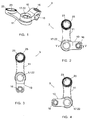
- Each sacral anchoring screw 1, 2 comprises a threaded base portion 7 intended to be inserted in the corresponding vertebra, a bearing surface 8 shaped as a portion of a sphere and a threaded proximal shank 9, and is polyaxial i.e. its shank 9 articulates with respect to its threaded base portion 7.
- this articulation is obtained by means of a spherical portion arranged at the distal end of the shank 9 and received in a spherical cavity centrally formed by the bearing surface 8, the wall forming the latter being crimped around this spherical portion.
- the principle of said screw is described in the above-mentioned document N° WO 98/55038 to which reference can be made for more details.
- Each screw 1 is intended to be implanted in the first vertebra of the sacrum and each screw 2 is intended to be implanted in the second vertebra of the sacrum; the two screws 1, 2 of a first sacrum anchor assembly are intended to be anchored onto the left of the sacrum relative to the axis of the spine, whilst the two screws 1, 2 of the second sacrum anchor assembly are intended to be anchored onto the right of the sacrum relative to this same axis.
- each link assembly 3 comprises a sacral connecting part 10 and a sacral anchor plate 11 assembled onto each other, the connecting part 10 being connected to the plate 11 in a direction perpendicular to the plane of the views in Figures 2 to 4 (or from bottom upwards in Figures 6 to 8 ), being polyaxially mobile i.e. with possible multidirectional tilting (cf. Figures 7 and 8 ), and pivoting (cf. Figures 2 to 4 ) in relation to this plate 11.
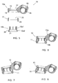
- the connecting part 10 comprises a main part 10a and a tubular part 10b for mounting on the said plate 11.
- the main part 10a comprises an orifice 15 for engaging on said connecting bar, a threaded plug or set screw 16 to clamp the rod in this orifice 15, to immobilise this rod relative to this part 10a, an orifice 17 for engaging on the shank 9 of the screw 1, and a groove 18 arranged in its wall delimiting this orifice 17 coaxially thereto.
- the portion of this orifice 17 intended to face the plate 19 is machined so as to form a recess 19 of conical or spherical shape allowing polyaxiality, as can be seen in Figures 6 to 8 .
- the tubular part 10b comprises a cylindrical part 10b1 and a part 10b2 shaped as a portion of a sphere.
- the cylindrical part 10b1 has a plurality of longitudinal slots leading to its edge opposite the part 10b2 and comprises an outer collar on its end opposite this same part 10b2, the assembly forming a plurality of press-fit teeth able to be press-fitted, or snapped, into the groove 18 as can be seen by comparison between Figures 5 and 6 .
- the part 10b2 outwardly forms a shoulder 20 having a surface in the shape of a portion of a sphere which, when press-fitting has been carried out, allows trapping of the plate 11 between the main part 10a and this shoulder, as can be seen in Figures 6 to 8 .
- the part 10b2 inwardly forms a bearing surface 21 shaped as a portion of a sphere intended to bear upon the said bearing surface 8 of a screw 1.
- This bearing surface 21 has a slightly larger radius than the bearing surface 8 and is of shorter height than the latter, which means that polyaxial clearance of the part 10 relative to this surface 8 is possible over about fifteen degrees either side of the neutral position shown in Figure 6 , as can be seen in Figures 7 and 8 .
- the plate 11 comprises a first orifice 22 intended to engage on the shank 9 of a screw 1 and a second orifice 23 intended to engage on the shank 9 of a screw 2, the orifices 17 and 22 being coaxial after assembling the part 10 and the plate 11.
- the second orifice 23 is surrounded by a surface 25 which can be slightly angled relative to the plane of this plate 11, as can be seen in Figure 1 , to obtain a corresponding anatomical angle between the plate 11 and the bearing surface 8, and this surface 25 also being knurled for non-sliding reception of a nut 5 or of the cross-piece 4 or of the iliac anchor plate 6 as described below.
- the nuts 5, in the illustrated example, are of the type having a lower part which engages in an orifice 22 or 23 and a hexagonal upper part used for handling.
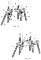
- a link assembly 3 is engaged on the connecting bar (not illustrated in Figures 9 to 14 for reasons of clarity); the other connecting parts included in the equipment are also engaged on this rod; the connecting bar thus equipped is then placed in position on the said bone anchoring members, and the link assembly 3 is engaged on the shanks 9 of the screws 1 and 2 ( Figure 9 ) until it comes to bear upon the bearing surfaces 8 formed in these screws; a nut 5 is then fully or party clamped on the shank 9 of the screw 2 ( Figure 10 ) to allow the link assembly 3 to obtain pre-positioning of the portion of the connecting bar extending at the vertebrae of the sacrum.
- the connecting bar is then rigidly affixed to the said anchor members included in the equipment; this affixing does not generate any stress on the fourth and fifth lumbar vertebrae or on the sacrum having regard to the possible tilting and pivoting of the connecting part 10 relative to the plate 11.
- a nut 5 is then placed in position and clamped ( Figure 11 ) to complete mounting the assembly, thereby locking the part 10 in the position that this part comes to assume as imposed by the position of the connecting bar.
- Figure 12 shows that the cross-piece 4 can be used to connect the left sacral anchor assembly to the right sacral anchor assembly at the two screws 2.
- the cross-piece 4 comprises oblong openings at its ends and the nuts 5 of these screws 2 clamp this cross-piece between them and the sacral anchor plates 11.
- each iliac anchor plate 6 has a double-bend shape, namely it comprises a first portion 6a pierced with an orifice able to be engaged on the shank 9 of a screw 2, a second portion 6b bent relative to the first portion 6a, and a third portion 6c bent relative to the portion 6b.
- the third portion 6c and the second portion 6b are pierced with an orifice to receive an anchor screw 30 in the iliac wing of the pelvis.
- the above-mentioned tilting of the surface 24 allows adequate orienting of the plate 6.
- the two iliac anchor plates 6 can be used according to needs, to obtain even further reinforced anchoring of the equipment if required.
- Figure 14 shows the simultaneous use of the cross-piece 4 and the plates 6, the cross-piece being positioned above portions 6a of the plates 6.
- the invention provides vertebral osteosynthesis equipment which, compared with approved equipments in the prior art, has the following determinant advantages:
Landscapes
- Health & Medical Sciences (AREA)
- Orthopedic Medicine & Surgery (AREA)
- Life Sciences & Earth Sciences (AREA)
- Neurology (AREA)
- Surgery (AREA)
- Heart & Thoracic Surgery (AREA)
- Engineering & Computer Science (AREA)
- Biomedical Technology (AREA)
- Nuclear Medicine, Radiotherapy & Molecular Imaging (AREA)
- Medical Informatics (AREA)
- Molecular Biology (AREA)
- Animal Behavior & Ethology (AREA)
- General Health & Medical Sciences (AREA)
- Public Health (AREA)
- Veterinary Medicine (AREA)
- Neurosurgery (AREA)
- Surgical Instruments (AREA)
Claims (7)
- Vorrichtung für Wirbelsäulenosteosynthese, die Folgendes umfasst:- mindestens eine Verbindungsstange, die in der Lage ist, mehrere Wirbel zu verbinden;- Knochenverankerungselemente, die zum Verankern dieser Verbindungsstange auf den Wirbeln geeignet sind;- Verbindungsteile, die das Verbinden der Verbindungsstange mit diesen Knochenverankerungselementen ermöglicht; und- mindestens eine Kreuzbein-Ankerbaugruppe (1 bis 3, 5); wobei jede Kreuzbein-Ankerbaugruppe Folgendes umfasst:- zwei Kreuzbein-Ankerschrauben (1, 2), wobei die erste dazu bestimmt ist, in den ersten Wirbel des Kreuzbeins implantiert zu werden, und die zweite dazu bestimmt ist, in den zweiten Wirbel des Kreuzbeins implantiert zu werden, wobei jede Schraube (1, 2) einen Basisabschnitt (7) mit Gewinde, der dazu bestimmt ist, in den entsprechenden Wirbel eingesetzt zu werden, eine Auflagefläche (8) und einen proximalen Schaft (9) mit Gewinde umfasst, wobei die Form der Auflagefläche (8) der ersten Schraube (1) ein Abschnitt einer Kugel ist;- eine Verbindungsbaugruppe (3), die Folgendes umfasst- einen Kreuzbein-Verbindungsteil (10), der eine Öffnung (15) für den Eingriff auf der Verbindungsstange, eine Öffnung (17) für den Eingriff auf dem Schaft (9) der ersten Schraube (1) und eine Auflagefläche (21) umfasst, die als ein Teil einer Kugel geformt ist, der in der Lage ist, auf der Auflagefläche (8), die in der ersten Schraube (1) gebildet ist, aufzuliegen, wobei dieses Aufliegen über Polyaxialität, d. h. dadurch erhalten wird, dass der Kreuzbein-Verbindungsteil (10) eine mögliche Neigung in mehrere Richtungen in Bezug zu der ersten Schraube (1) aufweist;- eine Kreuzbein-Ankerplatte (11), die eine erste Öffnung (22), die dazu bestimmt ist, auf dem Schaft (9) der ersten Schraube (1) einzugreifen, und eine zweite Öffnung (23) umfasst, die dazu bestimmt ist, auf dem Schaft (9) der zweiten Schraube (2) einzugreifen;- Mittel (10b, 18) zum Zusammenbauen des Kreuzbein-Verbindungsteils (10) mit der Kreuzbein-Ankerplatte (11), wobei dieses Zusammenbauen derart ist, dass die Öffnung (17) für den Eingriff auf dem Schaft (9) koaxial zu der ersten Öffnung (22) liegt, wobei der Kreuzbein-Verbindungsteil (10) mit der Kreuzbein-Ankerplatte (11) in einer Richtung parallel zu der Achse dieser Löcher (17, 22) verbunden ist und der Kreuzbein-Verbindungsteil (10) in der Lage ist, in Bezug zu der Kreuzbein-Ankerplatte (11) entlang dieser gleichen Achse zu schwenken;- zwei Muttern (5), wobei eine erste Mutter (5), die in der Lage ist, auf den Schaft (9) der ersten Schraube (1) geschraubt zu werden und derart gegen den Kreuzbein-Verbindungsteil (10) aufzuliegen, dass dieser Kreuzbein-Verbindungsteil (10) gegen die Auflagefläche (8), die in der ersten Schraube (1) gebildet ist, zur Immobilisierung gegenüber Kipp- und Schwenkbewegungen dieses Teils in Bezug zu der Kreuzbein-Ankerplatte (11) geklemmt wird, und wobei die zweite Mutter (5) in der Lage ist, auf den Schaft (9) der zweiten Schraube (2) geschraubt zu werden und derart gegen die Kreuzbein-Ankerplatte (11) aufzuliegen, dass diese Kreuzbein-Ankerplatte (11) gegen die Auflagefläche (8) geklemmt wird, die in der zweiten Schraube (2) gebildet ist.
- Vorrichtung nach Anspruch 1, dadurch gekennzeichnet, dass jede Kreuzbein-Ankerschraube (1, 2) polyaxial ist, d. h. ihr proximaler Schaft (9) mit Gewinde ist mit dem Basisabschnitt (7) mit Gewinde gelenkig.
- Vorrichtung nach Anspruch 1 oder 2, dadurch gekennzeichnet, dass sie Folgendes umfasst:- zwei Kreuzbein-Ankerbaugruppen (1 bis 3, 5), wobei eine dazu bestimmt ist, auf der linken Seite des Kreuzbeins in Bezug zu der Achse der Wirbelsäule verankert zu sein, und die andere dazu bestimmt ist, auf der rechten Seite des Kreuzbeins in Bezug zu dieser gleichen Achse verankert zu sein;- ein Querstück (4), das in der Lage ist, die zweiten Schrauben (2) dieser zwei Kreuzbein-Ankerbaugruppen (1 bis 3, 5) zu verbinden.
- Vorrichtung nach Anspruch 3, dadurch gekennzeichnet, dass das Querstück (4) an seinen Enden Öffnungen umfasst, die vorzugsweise länglich sind, und dadurch, dass die zweiten Muttern (5) dieses Querstück (4) zwischen sich und die Kreuzbein-Ankerplatten (11) klemmen.
- Vorrichtung nach einem der Ansprüche 1 bis 4, dadurch gekennzeichnet, dass sie mindestens eine Beckenankerplatte (6) umfasst, die eine doppelt gebogene Form aufweist, nämlich einen ersten Abschnitt (6a), der durch eine Öffnung durchbrochen ist, die in der Lage ist, auf dem Schaft (9) der zweiten Schraube (2) in Eingriff gebracht zu werden, einen zweiten Abschnitt (6b), der in Bezug zu dem ersten Abschnitt (6a) gebogen ist, und einen dritten Abschnitt (6c) umfasst, der in Bezug zu dem zweiten Abschnitt (6b) gebogen ist, wobei der dritte Abschnitt (6c) oder der zweite und dritte Abschnitt (6b, 6c) durch eine Öffnung durchbrochen sind, um eine Ankerschraube (30) in der Beckenschaufel des Beckens aufzunehmen.
- Vorrichtung nach Anspruch 4 oder Anspruch 5, dadurch gekennzeichnet, dass die Kreuzbein-Ankerplatten (11) um die zweiten Öffnungen (23) Zonen (25) umfassen, die eine unregelmäßige, z. B. gerändelte, Fläche aufweisen.
- Vorrichtung nach einem der Ansprüche 1 bis 6, dadurch gekennzeichnet, dass:- der Kreuzbein-Verbindungsteil (10) aus zwei Teilen besteht, die einen Hauptteil (10a), der die Eingriffsöffnungen (15, 17) umfasst, und einen röhrenförmigen Teil (10b) zum Zusammenbau auf der Kreuzbein-Ankerplatte (11) umfassen, der die Auflagefläche (21) umfasst, die als ein Abschnitt einer Kugel geformt ist und eine Schulter (20) bildet; und- die Mittel zum Zusammenbauen des Kreuzbein-Verbindungsteils (10) auf der Kreuzbein-Ankerplatte (11) Folgendes umfassen:- eine Nut (18), die in der Wand des Hauptteils (10a) angeordnet ist, die die Öffnung (17) für den Eingriff auf dem Schaft (9) der ersten Schraube (1) abgrenzt; und- Presspassungszähne, die in dem röhrenförmigen Teil (10b) angeordnet sind und in der Lage sind, durch Presspassung in dieser Nut (18) untergebracht zu werden, wobei die Kreuzbein-Ankerplatte (11) zwischen dem Hauptteil (10a) und der Schulter (20) des röhrenförmigen Teils (10b) eingekeilt ist, wenn diese Presspassung durchgeführt wird.
Applications Claiming Priority (2)
| Application Number | Priority Date | Filing Date | Title |
|---|---|---|---|
| FR1253284A FR2989264B1 (fr) | 2012-04-11 | 2012-04-11 | Materiel d'osteosynthese vertebrale |
| PCT/IB2013/052626 WO2013153482A1 (en) | 2012-04-11 | 2013-04-02 | Vertebral osteosynthesis equipment |
Publications (2)
| Publication Number | Publication Date |
|---|---|
| EP2836148A1 EP2836148A1 (de) | 2015-02-18 |
| EP2836148B1 true EP2836148B1 (de) | 2016-05-25 |
Family
ID=48446432
Family Applications (1)
| Application Number | Title | Priority Date | Filing Date |
|---|---|---|---|
| EP13723245.0A Active EP2836148B1 (de) | 2012-04-11 | 2013-04-02 | Vorrichtung für wirbelsäulenosteosynthese |
Country Status (5)
| Country | Link |
|---|---|
| US (1) | US9387015B2 (de) |
| EP (1) | EP2836148B1 (de) |
| ES (1) | ES2587739T3 (de) |
| FR (1) | FR2989264B1 (de) |
| WO (1) | WO2013153482A1 (de) |
Families Citing this family (18)
| Publication number | Priority date | Publication date | Assignee | Title |
|---|---|---|---|---|
| US8617216B2 (en) * | 2010-04-05 | 2013-12-31 | David L. Brumfield | Fully-adjustable bone fixation device |
| FR3010628B1 (fr) | 2013-09-18 | 2015-10-16 | Medicrea International | Procede permettant de realiser la courbure ideale d'une tige d'un materiel d'osteosynthese vertebrale destinee a etayer la colonne vertebrale d'un patient |
| FR3012030B1 (fr) | 2013-10-18 | 2015-12-25 | Medicrea International | Procede permettant de realiser la courbure ideale d'une tige d'un materiel d'osteosynthese vertebrale destinee a etayer la colonne vertebrale d'un patient |
| FR3019981B1 (fr) | 2014-04-17 | 2020-12-11 | Medicrea Int | Materiel d'osteosynthese vertebrale |
| US9872711B2 (en) * | 2014-10-21 | 2018-01-23 | Warsaw Orthopedic. Inc. | Spinal implant system and method |
| US9763703B2 (en) | 2015-05-05 | 2017-09-19 | Degen Medical, Inc. | Cross connectors, kits, and methods |
| FR3038218B1 (fr) | 2015-07-03 | 2017-07-21 | Orthopaedic & Spine Dev (Osd) | Implant de fixation sacro-iliaque pour une barre de liaison intervertebrale |
| EP3370657B1 (de) | 2015-11-04 | 2023-12-27 | Medicrea International | Vorrichtung zur rekonstruktiven wirbelsäulenchirurgie und zur messung der wirbelsäulenlänge |
| WO2018109556A1 (en) | 2016-12-12 | 2018-06-21 | Medicrea International | Systems and methods for patient-specific spinal implants |
| EP3612122B1 (de) | 2017-04-21 | 2023-12-20 | Medicrea International | System zur entwicklung einer oder mehrerer patientenspezifischer wirbelsäulenimplantate |
| US10918422B2 (en) | 2017-12-01 | 2021-02-16 | Medicrea International | Method and apparatus for inhibiting proximal junctional failure |
| WO2020201353A1 (en) | 2019-04-02 | 2020-10-08 | Medicrea International | Systems, methods, and devices for developing patient-specific spinal implants, treatments, operations, and/or procedures |
| US11925417B2 (en) | 2019-04-02 | 2024-03-12 | Medicrea International | Systems, methods, and devices for developing patient-specific spinal implants, treatments, operations, and/or procedures |
| US11944385B2 (en) | 2019-04-02 | 2024-04-02 | Medicrea International | Systems and methods for medical image analysis |
| US11769251B2 (en) | 2019-12-26 | 2023-09-26 | Medicrea International | Systems and methods for medical image analysis |
| US11426211B2 (en) * | 2020-10-28 | 2022-08-30 | Globus Medical, Inc. | Articulating connectors, systems, and methods thereof |
| US12318144B2 (en) | 2021-06-23 | 2025-06-03 | Medicrea International SA | Systems and methods for planning a patient-specific spinal correction |
| US12514644B1 (en) | 2025-01-09 | 2026-01-06 | Carlsmed, Inc. | Posterior fixation systems for spinal treatments |
Family Cites Families (21)
| Publication number | Priority date | Publication date | Assignee | Title |
|---|---|---|---|---|
| US4887595A (en) * | 1987-07-29 | 1989-12-19 | Acromed Corporation | Surgically implantable device for spinal columns |
| CH674709A5 (de) * | 1988-04-27 | 1990-07-13 | Sulzer Ag | |
| US5000165A (en) * | 1989-05-15 | 1991-03-19 | Watanabe Robert S | Lumbar spine rod fixation system |
| DE3923995A1 (de) * | 1989-07-20 | 1991-01-31 | Lutz Biedermann | Stabilisierungselement fuer knochen |
| US5127912A (en) * | 1990-10-05 | 1992-07-07 | R. Charles Ray | Sacral implant system |
| US5360429A (en) * | 1992-02-20 | 1994-11-01 | Jbs Societe Anonyme | Device for straightening, fixing, compressing, and elongating cervical vertebrae |
| EP0570929B1 (de) * | 1992-05-18 | 1995-06-28 | Pina Vertriebs Ag | Implantat für die Wirbeläule |
| US5397363A (en) * | 1992-08-11 | 1995-03-14 | Gelbard; Steven D. | Spinal stabilization implant system |
| US5306275A (en) * | 1992-12-31 | 1994-04-26 | Bryan Donald W | Lumbar spine fixation apparatus and method |
| SE9402130D0 (sv) * | 1994-06-17 | 1994-06-17 | Sven Olerud | Anordning samt förfarande för plattfixation av ben |
| IES77331B2 (en) * | 1997-06-03 | 1997-12-03 | Tecos Holdings Inc | Pluridirectional and modulable vertebral osteosynthesis device of small overall size |
| US5947968A (en) * | 1997-11-03 | 1999-09-07 | Rogozinski; Chaim | Graft anchor and method |
| CA2330705A1 (fr) * | 1998-04-29 | 1999-11-04 | Dimso (Distribution Medicale Du Sud-Ouest) | Systeme d'osteosynthese rachidienne pour une fixation anterieure |
| FR2829919B1 (fr) * | 2001-09-26 | 2003-12-19 | Spine Next Sa | Dispositif de fixation vertebral |
| US20040006342A1 (en) * | 2002-02-13 | 2004-01-08 | Moti Altarac | Posterior polyaxial plate system for the spine |
| US7717939B2 (en) * | 2004-03-31 | 2010-05-18 | Depuy Spine, Inc. | Rod attachment for head to head cross connector |
| FR2870712B1 (fr) * | 2004-05-26 | 2006-09-01 | Sdgi Holdings Inc | Implants pour dispositif d'osteosynthese rachidienne et ensemble les comprenant |
| US8029546B2 (en) * | 2005-12-15 | 2011-10-04 | Warsaw Orthopedic, Inc. | Variable angle offset spinal connector assembly |
| US8348976B2 (en) * | 2007-08-27 | 2013-01-08 | Kyphon Sarl | Spinous-process implants and methods of using the same |
| US20090093843A1 (en) * | 2007-10-05 | 2009-04-09 | Lemoine Jeremy J | Dynamic spine stabilization system |
| US20100174315A1 (en) * | 2008-12-16 | 2010-07-08 | Daniel Scodary | Device for spinal fusion |
-
2012
- 2012-04-11 FR FR1253284A patent/FR2989264B1/fr active Active
-
2013
- 2013-04-02 EP EP13723245.0A patent/EP2836148B1/de active Active
- 2013-04-02 WO PCT/IB2013/052626 patent/WO2013153482A1/en not_active Ceased
- 2013-04-02 ES ES13723245.0T patent/ES2587739T3/es active Active
-
2014
- 2014-10-09 US US14/510,538 patent/US9387015B2/en active Active
Non-Patent Citations (1)
| Title |
|---|
| None * |
Also Published As
| Publication number | Publication date |
|---|---|
| FR2989264A1 (fr) | 2013-10-18 |
| WO2013153482A1 (en) | 2013-10-17 |
| ES2587739T3 (es) | 2016-10-26 |
| FR2989264B1 (fr) | 2014-05-09 |
| US20150025576A1 (en) | 2015-01-22 |
| US9387015B2 (en) | 2016-07-12 |
| EP2836148A1 (de) | 2015-02-18 |
Similar Documents
| Publication | Publication Date | Title |
|---|---|---|
| EP2836148B1 (de) | Vorrichtung für wirbelsäulenosteosynthese | |
| EP1729664B1 (de) | Wirbelsäulenfixiersystem mit kopf-an-kopf-konnektoren | |
| EP1638472B1 (de) | Wirbel-osteosynthese-gerät | |
| US7717938B2 (en) | Dual rod cross connectors and inserter tools | |
| US9486247B2 (en) | Rod attachment for head to head cross connector | |
| US20060052784A1 (en) | Polyaxial device for spine stabilization during osteosynthesis | |
| US20060052783A1 (en) | Polyaxial device for spine stabilization during osteosynthesis | |
| US11406427B2 (en) | Low profile connectors | |
| WO1995010239A1 (en) | Spinal treatment and long bone fixation apparatus and method | |
| EP0675700A1 (de) | Wirbelsäulenbehandlung und apparatur und methode zur wirbelsäulenrichtung | |
| AU2024205067B2 (en) | Pedicle screws | |
| US10413333B2 (en) | System and method for spinal fixation via a trans-facet pedicle screw assembly | |
| US20260020882A1 (en) | Triangulation assembly for rectifying vertebrae, and spinal osteosynthesis system comprising such assemblies | |
| US11812923B2 (en) | Spinal fixation device | |
| HK40090177B (en) | Pedicle screws | |
| HK40090177A (en) | Pedicle screws |
Legal Events
| Date | Code | Title | Description |
|---|---|---|---|
| PUAI | Public reference made under article 153(3) epc to a published international application that has entered the european phase |
Free format text: ORIGINAL CODE: 0009012 |
|
| 17P | Request for examination filed |
Effective date: 20140930 |
|
| AK | Designated contracting states |
Kind code of ref document: A1 Designated state(s): AL AT BE BG CH CY CZ DE DK EE ES FI FR GB GR HR HU IE IS IT LI LT LU LV MC MK MT NL NO PL PT RO RS SE SI SK SM TR |
|
| AX | Request for extension of the european patent |
Extension state: BA ME |
|
| DAX | Request for extension of the european patent (deleted) | ||
| GRAP | Despatch of communication of intention to grant a patent |
Free format text: ORIGINAL CODE: EPIDOSNIGR1 |
|
| INTG | Intention to grant announced |
Effective date: 20160129 |
|
| GRAS | Grant fee paid |
Free format text: ORIGINAL CODE: EPIDOSNIGR3 |
|
| GRAA | (expected) grant |
Free format text: ORIGINAL CODE: 0009210 |
|
| AK | Designated contracting states |
Kind code of ref document: B1 Designated state(s): AL AT BE BG CH CY CZ DE DK EE ES FI FR GB GR HR HU IE IS IT LI LT LU LV MC MK MT NL NO PL PT RO RS SE SI SK SM TR |
|
| REG | Reference to a national code |
Ref country code: GB Ref legal event code: FG4D |
|
| REG | Reference to a national code |
Ref country code: CH Ref legal event code: EP |
|
| REG | Reference to a national code |
Ref country code: IE Ref legal event code: FG4D Ref country code: AT Ref legal event code: REF Ref document number: 801578 Country of ref document: AT Kind code of ref document: T Effective date: 20160615 |
|
| REG | Reference to a national code |
Ref country code: DE Ref legal event code: R096 Ref document number: 602013007984 Country of ref document: DE |
|
| REG | Reference to a national code |
Ref country code: LT Ref legal event code: MG4D |
|
| REG | Reference to a national code |
Ref country code: NL Ref legal event code: MP Effective date: 20160525 |
|
| REG | Reference to a national code |
Ref country code: ES Ref legal event code: FG2A Ref document number: 2587739 Country of ref document: ES Kind code of ref document: T3 Effective date: 20161026 |
|
| PG25 | Lapsed in a contracting state [announced via postgrant information from national office to epo] |
Ref country code: NL Free format text: LAPSE BECAUSE OF FAILURE TO SUBMIT A TRANSLATION OF THE DESCRIPTION OR TO PAY THE FEE WITHIN THE PRESCRIBED TIME-LIMIT Effective date: 20160525 Ref country code: NO Free format text: LAPSE BECAUSE OF FAILURE TO SUBMIT A TRANSLATION OF THE DESCRIPTION OR TO PAY THE FEE WITHIN THE PRESCRIBED TIME-LIMIT Effective date: 20160825 Ref country code: FI Free format text: LAPSE BECAUSE OF FAILURE TO SUBMIT A TRANSLATION OF THE DESCRIPTION OR TO PAY THE FEE WITHIN THE PRESCRIBED TIME-LIMIT Effective date: 20160525 Ref country code: LT Free format text: LAPSE BECAUSE OF FAILURE TO SUBMIT A TRANSLATION OF THE DESCRIPTION OR TO PAY THE FEE WITHIN THE PRESCRIBED TIME-LIMIT Effective date: 20160525 |
|
| REG | Reference to a national code |
Ref country code: AT Ref legal event code: MK05 Ref document number: 801578 Country of ref document: AT Kind code of ref document: T Effective date: 20160525 |
|
| PG25 | Lapsed in a contracting state [announced via postgrant information from national office to epo] |
Ref country code: GR Free format text: LAPSE BECAUSE OF FAILURE TO SUBMIT A TRANSLATION OF THE DESCRIPTION OR TO PAY THE FEE WITHIN THE PRESCRIBED TIME-LIMIT Effective date: 20160826 Ref country code: RS Free format text: LAPSE BECAUSE OF FAILURE TO SUBMIT A TRANSLATION OF THE DESCRIPTION OR TO PAY THE FEE WITHIN THE PRESCRIBED TIME-LIMIT Effective date: 20160525 Ref country code: SE Free format text: LAPSE BECAUSE OF FAILURE TO SUBMIT A TRANSLATION OF THE DESCRIPTION OR TO PAY THE FEE WITHIN THE PRESCRIBED TIME-LIMIT Effective date: 20160525 Ref country code: LV Free format text: LAPSE BECAUSE OF FAILURE TO SUBMIT A TRANSLATION OF THE DESCRIPTION OR TO PAY THE FEE WITHIN THE PRESCRIBED TIME-LIMIT Effective date: 20160525 Ref country code: PT Free format text: LAPSE BECAUSE OF FAILURE TO SUBMIT A TRANSLATION OF THE DESCRIPTION OR TO PAY THE FEE WITHIN THE PRESCRIBED TIME-LIMIT Effective date: 20160926 |
|
| PG25 | Lapsed in a contracting state [announced via postgrant information from national office to epo] |
Ref country code: IT Free format text: LAPSE BECAUSE OF FAILURE TO SUBMIT A TRANSLATION OF THE DESCRIPTION OR TO PAY THE FEE WITHIN THE PRESCRIBED TIME-LIMIT Effective date: 20160525 |
|
| PG25 | Lapsed in a contracting state [announced via postgrant information from national office to epo] |
Ref country code: RO Free format text: LAPSE BECAUSE OF FAILURE TO SUBMIT A TRANSLATION OF THE DESCRIPTION OR TO PAY THE FEE WITHIN THE PRESCRIBED TIME-LIMIT Effective date: 20160525 Ref country code: CZ Free format text: LAPSE BECAUSE OF FAILURE TO SUBMIT A TRANSLATION OF THE DESCRIPTION OR TO PAY THE FEE WITHIN THE PRESCRIBED TIME-LIMIT Effective date: 20160525 Ref country code: EE Free format text: LAPSE BECAUSE OF FAILURE TO SUBMIT A TRANSLATION OF THE DESCRIPTION OR TO PAY THE FEE WITHIN THE PRESCRIBED TIME-LIMIT Effective date: 20160525 Ref country code: DK Free format text: LAPSE BECAUSE OF FAILURE TO SUBMIT A TRANSLATION OF THE DESCRIPTION OR TO PAY THE FEE WITHIN THE PRESCRIBED TIME-LIMIT Effective date: 20160525 Ref country code: SK Free format text: LAPSE BECAUSE OF FAILURE TO SUBMIT A TRANSLATION OF THE DESCRIPTION OR TO PAY THE FEE WITHIN THE PRESCRIBED TIME-LIMIT Effective date: 20160525 |
|
| PG25 | Lapsed in a contracting state [announced via postgrant information from national office to epo] |
Ref country code: PL Free format text: LAPSE BECAUSE OF FAILURE TO SUBMIT A TRANSLATION OF THE DESCRIPTION OR TO PAY THE FEE WITHIN THE PRESCRIBED TIME-LIMIT Effective date: 20160525 Ref country code: BE Free format text: LAPSE BECAUSE OF FAILURE TO SUBMIT A TRANSLATION OF THE DESCRIPTION OR TO PAY THE FEE WITHIN THE PRESCRIBED TIME-LIMIT Effective date: 20160525 Ref country code: SM Free format text: LAPSE BECAUSE OF FAILURE TO SUBMIT A TRANSLATION OF THE DESCRIPTION OR TO PAY THE FEE WITHIN THE PRESCRIBED TIME-LIMIT Effective date: 20160525 Ref country code: AT Free format text: LAPSE BECAUSE OF FAILURE TO SUBMIT A TRANSLATION OF THE DESCRIPTION OR TO PAY THE FEE WITHIN THE PRESCRIBED TIME-LIMIT Effective date: 20160525 |
|
| REG | Reference to a national code |
Ref country code: DE Ref legal event code: R097 Ref document number: 602013007984 Country of ref document: DE |
|
| PLBE | No opposition filed within time limit |
Free format text: ORIGINAL CODE: 0009261 |
|
| STAA | Information on the status of an ep patent application or granted ep patent |
Free format text: STATUS: NO OPPOSITION FILED WITHIN TIME LIMIT |
|
| REG | Reference to a national code |
Ref country code: FR Ref legal event code: PLFP Year of fee payment: 5 |
|
| 26N | No opposition filed |
Effective date: 20170228 |
|
| PG25 | Lapsed in a contracting state [announced via postgrant information from national office to epo] |
Ref country code: SI Free format text: LAPSE BECAUSE OF FAILURE TO SUBMIT A TRANSLATION OF THE DESCRIPTION OR TO PAY THE FEE WITHIN THE PRESCRIBED TIME-LIMIT Effective date: 20160525 |
|
| REG | Reference to a national code |
Ref country code: CH Ref legal event code: PL |
|
| REG | Reference to a national code |
Ref country code: IE Ref legal event code: MM4A |
|
| PG25 | Lapsed in a contracting state [announced via postgrant information from national office to epo] |
Ref country code: MC Free format text: LAPSE BECAUSE OF FAILURE TO SUBMIT A TRANSLATION OF THE DESCRIPTION OR TO PAY THE FEE WITHIN THE PRESCRIBED TIME-LIMIT Effective date: 20160525 |
|
| PG25 | Lapsed in a contracting state [announced via postgrant information from national office to epo] |
Ref country code: CH Free format text: LAPSE BECAUSE OF NON-PAYMENT OF DUE FEES Effective date: 20170430 Ref country code: LU Free format text: LAPSE BECAUSE OF NON-PAYMENT OF DUE FEES Effective date: 20170402 Ref country code: LI Free format text: LAPSE BECAUSE OF NON-PAYMENT OF DUE FEES Effective date: 20170430 |
|
| REG | Reference to a national code |
Ref country code: FR Ref legal event code: PLFP Year of fee payment: 6 |
|
| PG25 | Lapsed in a contracting state [announced via postgrant information from national office to epo] |
Ref country code: IE Free format text: LAPSE BECAUSE OF NON-PAYMENT OF DUE FEES Effective date: 20170402 |
|
| PGFP | Annual fee paid to national office [announced via postgrant information from national office to epo] |
Ref country code: ES Payment date: 20180525 Year of fee payment: 6 Ref country code: DE Payment date: 20180522 Year of fee payment: 6 |
|
| PG25 | Lapsed in a contracting state [announced via postgrant information from national office to epo] |
Ref country code: MT Free format text: LAPSE BECAUSE OF NON-PAYMENT OF DUE FEES Effective date: 20170402 |
|
| PG25 | Lapsed in a contracting state [announced via postgrant information from national office to epo] |
Ref country code: AL Free format text: LAPSE BECAUSE OF FAILURE TO SUBMIT A TRANSLATION OF THE DESCRIPTION OR TO PAY THE FEE WITHIN THE PRESCRIBED TIME-LIMIT Effective date: 20160525 |
|
| PGFP | Annual fee paid to national office [announced via postgrant information from national office to epo] |
Ref country code: GB Payment date: 20180518 Year of fee payment: 6 |
|
| PG25 | Lapsed in a contracting state [announced via postgrant information from national office to epo] |
Ref country code: HU Free format text: LAPSE BECAUSE OF FAILURE TO SUBMIT A TRANSLATION OF THE DESCRIPTION OR TO PAY THE FEE WITHIN THE PRESCRIBED TIME-LIMIT; INVALID AB INITIO Effective date: 20130402 |
|
| PG25 | Lapsed in a contracting state [announced via postgrant information from national office to epo] |
Ref country code: BG Free format text: LAPSE BECAUSE OF FAILURE TO SUBMIT A TRANSLATION OF THE DESCRIPTION OR TO PAY THE FEE WITHIN THE PRESCRIBED TIME-LIMIT Effective date: 20160525 |
|
| PG25 | Lapsed in a contracting state [announced via postgrant information from national office to epo] |
Ref country code: CY Free format text: LAPSE BECAUSE OF FAILURE TO SUBMIT A TRANSLATION OF THE DESCRIPTION OR TO PAY THE FEE WITHIN THE PRESCRIBED TIME-LIMIT Effective date: 20160525 |
|
| REG | Reference to a national code |
Ref country code: DE Ref legal event code: R119 Ref document number: 602013007984 Country of ref document: DE |
|
| PG25 | Lapsed in a contracting state [announced via postgrant information from national office to epo] |
Ref country code: MK Free format text: LAPSE BECAUSE OF FAILURE TO SUBMIT A TRANSLATION OF THE DESCRIPTION OR TO PAY THE FEE WITHIN THE PRESCRIBED TIME-LIMIT Effective date: 20160525 |
|
| GBPC | Gb: european patent ceased through non-payment of renewal fee |
Effective date: 20190402 |
|
| PG25 | Lapsed in a contracting state [announced via postgrant information from national office to epo] |
Ref country code: GB Free format text: LAPSE BECAUSE OF NON-PAYMENT OF DUE FEES Effective date: 20190402 Ref country code: DE Free format text: LAPSE BECAUSE OF NON-PAYMENT OF DUE FEES Effective date: 20191101 |
|
| PG25 | Lapsed in a contracting state [announced via postgrant information from national office to epo] |
Ref country code: TR Free format text: LAPSE BECAUSE OF FAILURE TO SUBMIT A TRANSLATION OF THE DESCRIPTION OR TO PAY THE FEE WITHIN THE PRESCRIBED TIME-LIMIT Effective date: 20160525 |
|
| PG25 | Lapsed in a contracting state [announced via postgrant information from national office to epo] |
Ref country code: HR Free format text: LAPSE BECAUSE OF FAILURE TO SUBMIT A TRANSLATION OF THE DESCRIPTION OR TO PAY THE FEE WITHIN THE PRESCRIBED TIME-LIMIT Effective date: 20160525 |
|
| PG25 | Lapsed in a contracting state [announced via postgrant information from national office to epo] |
Ref country code: IS Free format text: LAPSE BECAUSE OF FAILURE TO SUBMIT A TRANSLATION OF THE DESCRIPTION OR TO PAY THE FEE WITHIN THE PRESCRIBED TIME-LIMIT Effective date: 20160925 |
|
| REG | Reference to a national code |
Ref country code: ES Ref legal event code: FD2A Effective date: 20200828 |
|
| PG25 | Lapsed in a contracting state [announced via postgrant information from national office to epo] |
Ref country code: ES Free format text: LAPSE BECAUSE OF NON-PAYMENT OF DUE FEES Effective date: 20190403 |
|
| PGFP | Annual fee paid to national office [announced via postgrant information from national office to epo] |
Ref country code: FR Payment date: 20250319 Year of fee payment: 13 |