EP2836115B1 - Sensor and circuitry for wireless intracranial pressure monitoring - Google Patents
Sensor and circuitry for wireless intracranial pressure monitoring Download PDFInfo
- Publication number
- EP2836115B1 EP2836115B1 EP12873949.7A EP12873949A EP2836115B1 EP 2836115 B1 EP2836115 B1 EP 2836115B1 EP 12873949 A EP12873949 A EP 12873949A EP 2836115 B1 EP2836115 B1 EP 2836115B1
- Authority
- EP
- European Patent Office
- Prior art keywords
- monitoring device
- diaphragm
- intracranial pressure
- strain gauges
- disposed
- Prior art date
- Legal status (The legal status is an assumption and is not a legal conclusion. Google has not performed a legal analysis and makes no representation as to the accuracy of the status listed.)
- Active
Links
- 238000007917 intracranial administration Methods 0.000 title claims description 70
- 238000012544 monitoring process Methods 0.000 title description 16
- 238000012806 monitoring device Methods 0.000 claims description 115
- 210000003625 skull Anatomy 0.000 claims description 23
- 238000003860 storage Methods 0.000 claims description 19
- 230000001939 inductive effect Effects 0.000 claims description 15
- 239000003990 capacitor Substances 0.000 claims description 5
- 230000004044 response Effects 0.000 claims description 5
- RTAQQCXQSZGOHL-UHFFFAOYSA-N Titanium Chemical compound [Ti] RTAQQCXQSZGOHL-UHFFFAOYSA-N 0.000 claims description 3
- 239000010936 titanium Substances 0.000 claims description 3
- 229910052719 titanium Inorganic materials 0.000 claims description 3
- 210000000988 bone and bone Anatomy 0.000 claims description 2
- 230000006835 compression Effects 0.000 claims description 2
- 238000007906 compression Methods 0.000 claims description 2
- 238000004891 communication Methods 0.000 description 29
- 238000000034 method Methods 0.000 description 28
- SXZSFWHOSHAKMN-UHFFFAOYSA-N 2,3,4,4',5-Pentachlorobiphenyl Chemical compound C1=CC(Cl)=CC=C1C1=CC(Cl)=C(Cl)C(Cl)=C1Cl SXZSFWHOSHAKMN-UHFFFAOYSA-N 0.000 description 20
- 238000005259 measurement Methods 0.000 description 16
- 230000005540 biological transmission Effects 0.000 description 13
- 238000002513 implantation Methods 0.000 description 13
- 230000008878 coupling Effects 0.000 description 11
- 238000010168 coupling process Methods 0.000 description 11
- 238000005859 coupling reaction Methods 0.000 description 11
- 239000000463 material Substances 0.000 description 10
- 210000001519 tissue Anatomy 0.000 description 10
- 230000001052 transient effect Effects 0.000 description 10
- 230000000694 effects Effects 0.000 description 9
- 210000001175 cerebrospinal fluid Anatomy 0.000 description 8
- 230000008859 change Effects 0.000 description 8
- 239000004593 Epoxy Substances 0.000 description 7
- 208000012868 Overgrowth Diseases 0.000 description 7
- 210000004556 brain Anatomy 0.000 description 7
- 230000007774 longterm Effects 0.000 description 7
- 230000002093 peripheral effect Effects 0.000 description 7
- 230000006870 function Effects 0.000 description 6
- 210000003128 head Anatomy 0.000 description 5
- 239000007943 implant Substances 0.000 description 5
- 229910052751 metal Inorganic materials 0.000 description 5
- 239000002184 metal Substances 0.000 description 5
- 208000024891 symptom Diseases 0.000 description 5
- XKRFYHLGVUSROY-UHFFFAOYSA-N Argon Chemical compound [Ar] XKRFYHLGVUSROY-UHFFFAOYSA-N 0.000 description 4
- 241001269524 Dura Species 0.000 description 4
- 229920003171 Poly (ethylene oxide) Polymers 0.000 description 4
- VYPSYNLAJGMNEJ-UHFFFAOYSA-N Silicium dioxide Chemical compound O=[Si]=O VYPSYNLAJGMNEJ-UHFFFAOYSA-N 0.000 description 4
- 239000000853 adhesive Substances 0.000 description 4
- 230000001070 adhesive effect Effects 0.000 description 4
- 238000004458 analytical method Methods 0.000 description 4
- 230000004872 arterial blood pressure Effects 0.000 description 4
- 230000001276 controlling effect Effects 0.000 description 4
- 238000003745 diagnosis Methods 0.000 description 4
- 229940079593 drug Drugs 0.000 description 4
- 239000003814 drug Substances 0.000 description 4
- 239000007789 gas Substances 0.000 description 4
- 230000007935 neutral effect Effects 0.000 description 4
- 201000003077 normal pressure hydrocephalus Diseases 0.000 description 4
- 229920000036 polyvinylpyrrolidone Polymers 0.000 description 4
- 235000013855 polyvinylpyrrolidone Nutrition 0.000 description 4
- 238000012545 processing Methods 0.000 description 4
- 231100000241 scar Toxicity 0.000 description 4
- 238000007789 sealing Methods 0.000 description 4
- 230000000007 visual effect Effects 0.000 description 4
- 208000006011 Stroke Diseases 0.000 description 3
- 210000001367 artery Anatomy 0.000 description 3
- 230000000295 complement effect Effects 0.000 description 3
- 238000013461 design Methods 0.000 description 3
- 238000001514 detection method Methods 0.000 description 3
- 239000012530 fluid Substances 0.000 description 3
- 238000003780 insertion Methods 0.000 description 3
- 230000037431 insertion Effects 0.000 description 3
- 238000004519 manufacturing process Methods 0.000 description 3
- 238000006213 oxygenation reaction Methods 0.000 description 3
- 238000010079 rubber tapping Methods 0.000 description 3
- 239000004065 semiconductor Substances 0.000 description 3
- 229940123587 Cell cycle inhibitor Drugs 0.000 description 2
- 229940121363 anti-inflammatory agent Drugs 0.000 description 2
- 239000002260 anti-inflammatory agent Substances 0.000 description 2
- 229940127218 antiplatelet drug Drugs 0.000 description 2
- 239000004019 antithrombin Substances 0.000 description 2
- 229910052786 argon Inorganic materials 0.000 description 2
- 230000036772 blood pressure Effects 0.000 description 2
- 238000009530 blood pressure measurement Methods 0.000 description 2
- 210000001715 carotid artery Anatomy 0.000 description 2
- 230000003788 cerebral perfusion Effects 0.000 description 2
- 150000001875 compounds Chemical class 0.000 description 2
- 230000002596 correlated effect Effects 0.000 description 2
- 230000000875 corresponding effect Effects 0.000 description 2
- 238000010586 diagram Methods 0.000 description 2
- 238000005516 engineering process Methods 0.000 description 2
- 239000003527 fibrinolytic agent Substances 0.000 description 2
- -1 for example Substances 0.000 description 2
- PCHJSUWPFVWCPO-UHFFFAOYSA-N gold Chemical compound [Au] PCHJSUWPFVWCPO-UHFFFAOYSA-N 0.000 description 2
- 229910052737 gold Inorganic materials 0.000 description 2
- 239000010931 gold Substances 0.000 description 2
- 230000005484 gravity Effects 0.000 description 2
- 239000001307 helium Substances 0.000 description 2
- 229910052734 helium Inorganic materials 0.000 description 2
- SWQJXJOGLNCZEY-UHFFFAOYSA-N helium atom Chemical compound [He] SWQJXJOGLNCZEY-UHFFFAOYSA-N 0.000 description 2
- 239000000017 hydrogel Substances 0.000 description 2
- 208000015181 infectious disease Diseases 0.000 description 2
- 239000007788 liquid Substances 0.000 description 2
- 230000007246 mechanism Effects 0.000 description 2
- LFGREXWGYUGZLY-UHFFFAOYSA-N phosphoryl Chemical group [P]=O LFGREXWGYUGZLY-UHFFFAOYSA-N 0.000 description 2
- 230000004962 physiological condition Effects 0.000 description 2
- 239000000106 platelet aggregation inhibitor Substances 0.000 description 2
- 239000001267 polyvinylpyrrolidone Substances 0.000 description 2
- 238000004382 potting Methods 0.000 description 2
- 230000036387 respiratory rate Effects 0.000 description 2
- 230000004043 responsiveness Effects 0.000 description 2
- 235000012239 silicon dioxide Nutrition 0.000 description 2
- 239000000377 silicon dioxide Substances 0.000 description 2
- 229910052709 silver Inorganic materials 0.000 description 2
- 239000004332 silver Substances 0.000 description 2
- 229910001220 stainless steel Inorganic materials 0.000 description 2
- 239000010935 stainless steel Substances 0.000 description 2
- 229960000103 thrombolytic agent Drugs 0.000 description 2
- 230000007704 transition Effects 0.000 description 2
- 206010019233 Headaches Diseases 0.000 description 1
- 208000032843 Hemorrhage Diseases 0.000 description 1
- XUIMIQQOPSSXEZ-UHFFFAOYSA-N Silicon Chemical compound [Si] XUIMIQQOPSSXEZ-UHFFFAOYSA-N 0.000 description 1
- 206010040893 Skin necrosis Diseases 0.000 description 1
- 206010042674 Swelling Diseases 0.000 description 1
- 241000615754 Tentorium Species 0.000 description 1
- 241000746998 Tragus Species 0.000 description 1
- 230000001154 acute effect Effects 0.000 description 1
- 238000004873 anchoring Methods 0.000 description 1
- 230000003466 anti-cipated effect Effects 0.000 description 1
- 238000013459 approach Methods 0.000 description 1
- 238000013528 artificial neural network Methods 0.000 description 1
- 235000013405 beer Nutrition 0.000 description 1
- 230000009286 beneficial effect Effects 0.000 description 1
- 230000002457 bidirectional effect Effects 0.000 description 1
- 239000000560 biocompatible material Substances 0.000 description 1
- 230000015572 biosynthetic process Effects 0.000 description 1
- 238000009924 canning Methods 0.000 description 1
- 230000000747 cardiac effect Effects 0.000 description 1
- 230000015556 catabolic process Effects 0.000 description 1
- 239000000919 ceramic Substances 0.000 description 1
- 238000006243 chemical reaction Methods 0.000 description 1
- 238000003759 clinical diagnosis Methods 0.000 description 1
- 230000008602 contraction Effects 0.000 description 1
- 238000012937 correction Methods 0.000 description 1
- 230000003247 decreasing effect Effects 0.000 description 1
- 230000006866 deterioration Effects 0.000 description 1
- 208000002173 dizziness Diseases 0.000 description 1
- 238000005553 drilling Methods 0.000 description 1
- 210000005069 ears Anatomy 0.000 description 1
- 238000009429 electrical wiring Methods 0.000 description 1
- 230000005670 electromagnetic radiation Effects 0.000 description 1
- 230000007613 environmental effect Effects 0.000 description 1
- 230000000763 evoking effect Effects 0.000 description 1
- 210000003195 fascia Anatomy 0.000 description 1
- 239000000835 fiber Substances 0.000 description 1
- 238000001914 filtration Methods 0.000 description 1
- 238000009499 grossing Methods 0.000 description 1
- 231100000869 headache Toxicity 0.000 description 1
- 230000035876 healing Effects 0.000 description 1
- 208000003906 hydrocephalus Diseases 0.000 description 1
- 238000011065 in-situ storage Methods 0.000 description 1
- 238000010348 incorporation Methods 0.000 description 1
- 208000014674 injury Diseases 0.000 description 1
- 238000011900 installation process Methods 0.000 description 1
- 238000007914 intraventricular administration Methods 0.000 description 1
- 230000001788 irregular Effects 0.000 description 1
- 238000002595 magnetic resonance imaging Methods 0.000 description 1
- 239000003550 marker Substances 0.000 description 1
- 238000007620 mathematical function Methods 0.000 description 1
- 238000004377 microelectronic Methods 0.000 description 1
- 230000010363 phase shift Effects 0.000 description 1
- 230000000704 physical effect Effects 0.000 description 1
- 229920003023 plastic Polymers 0.000 description 1
- 239000004033 plastic Substances 0.000 description 1
- 150000003071 polychlorinated biphenyls Chemical class 0.000 description 1
- 230000008569 process Effects 0.000 description 1
- 230000010349 pulsation Effects 0.000 description 1
- 230000008672 reprogramming Effects 0.000 description 1
- 230000000241 respiratory effect Effects 0.000 description 1
- 210000004761 scalp Anatomy 0.000 description 1
- 230000035945 sensitivity Effects 0.000 description 1
- 230000011664 signaling Effects 0.000 description 1
- 229910052710 silicon Inorganic materials 0.000 description 1
- 239000010703 silicon Substances 0.000 description 1
- 238000013179 statistical model Methods 0.000 description 1
- 230000000638 stimulation Effects 0.000 description 1
- 239000000126 substance Substances 0.000 description 1
- 230000008961 swelling Effects 0.000 description 1
- 239000003826 tablet Substances 0.000 description 1
- 238000012546 transfer Methods 0.000 description 1
- 230000008733 trauma Effects 0.000 description 1
- 230000005641 tunneling Effects 0.000 description 1
- 230000002792 vascular Effects 0.000 description 1
- 210000003462 vein Anatomy 0.000 description 1
- 230000002861 ventricular Effects 0.000 description 1
- 238000003466 welding Methods 0.000 description 1
Images


Classifications
-
- A—HUMAN NECESSITIES
- A61—MEDICAL OR VETERINARY SCIENCE; HYGIENE
- A61B—DIAGNOSIS; SURGERY; IDENTIFICATION
- A61B5/00—Measuring for diagnostic purposes; Identification of persons
- A61B5/03—Detecting, measuring or recording fluid pressure within the body other than blood pressure, e.g. cerebral pressure; Measuring pressure in body tissues or organs
- A61B5/031—Intracranial pressure
-
- A—HUMAN NECESSITIES
- A61—MEDICAL OR VETERINARY SCIENCE; HYGIENE
- A61B—DIAGNOSIS; SURGERY; IDENTIFICATION
- A61B5/00—Measuring for diagnostic purposes; Identification of persons
- A61B5/103—Detecting, measuring or recording devices for testing the shape, pattern, colour, size or movement of the body or parts thereof, for diagnostic purposes
- A61B5/11—Measuring movement of the entire body or parts thereof, e.g. head or hand tremor, mobility of a limb
- A61B5/1116—Determining posture transitions
- A61B5/1117—Fall detection
-
- A—HUMAN NECESSITIES
- A61—MEDICAL OR VETERINARY SCIENCE; HYGIENE
- A61B—DIAGNOSIS; SURGERY; IDENTIFICATION
- A61B5/00—Measuring for diagnostic purposes; Identification of persons
- A61B5/68—Arrangements of detecting, measuring or recording means, e.g. sensors, in relation to patient
- A61B5/6846—Arrangements of detecting, measuring or recording means, e.g. sensors, in relation to patient specially adapted to be brought in contact with an internal body part, i.e. invasive
- A61B5/6847—Arrangements of detecting, measuring or recording means, e.g. sensors, in relation to patient specially adapted to be brought in contact with an internal body part, i.e. invasive mounted on an invasive device
- A61B5/6864—Burr holes
-
- A—HUMAN NECESSITIES
- A61—MEDICAL OR VETERINARY SCIENCE; HYGIENE
- A61B—DIAGNOSIS; SURGERY; IDENTIFICATION
- A61B2562/00—Details of sensors; Constructional details of sensor housings or probes; Accessories for sensors
- A61B2562/02—Details of sensors specially adapted for in-vivo measurements
- A61B2562/0219—Inertial sensors, e.g. accelerometers, gyroscopes, tilt switches
-
- A—HUMAN NECESSITIES
- A61—MEDICAL OR VETERINARY SCIENCE; HYGIENE
- A61B—DIAGNOSIS; SURGERY; IDENTIFICATION
- A61B2562/00—Details of sensors; Constructional details of sensor housings or probes; Accessories for sensors
- A61B2562/02—Details of sensors specially adapted for in-vivo measurements
- A61B2562/0247—Pressure sensors
-
- A—HUMAN NECESSITIES
- A61—MEDICAL OR VETERINARY SCIENCE; HYGIENE
- A61B—DIAGNOSIS; SURGERY; IDENTIFICATION
- A61B2562/00—Details of sensors; Constructional details of sensor housings or probes; Accessories for sensors
- A61B2562/02—Details of sensors specially adapted for in-vivo measurements
- A61B2562/0261—Strain gauges
-
- A—HUMAN NECESSITIES
- A61—MEDICAL OR VETERINARY SCIENCE; HYGIENE
- A61B—DIAGNOSIS; SURGERY; IDENTIFICATION
- A61B2562/00—Details of sensors; Constructional details of sensor housings or probes; Accessories for sensors
- A61B2562/04—Arrangements of multiple sensors of the same type
- A61B2562/046—Arrangements of multiple sensors of the same type in a matrix array
-
- A—HUMAN NECESSITIES
- A61—MEDICAL OR VETERINARY SCIENCE; HYGIENE
- A61B—DIAGNOSIS; SURGERY; IDENTIFICATION
- A61B2562/00—Details of sensors; Constructional details of sensor housings or probes; Accessories for sensors
- A61B2562/16—Details of sensor housings or probes; Details of structural supports for sensors
- A61B2562/168—Fluid filled sensor housings
-
- A—HUMAN NECESSITIES
- A61—MEDICAL OR VETERINARY SCIENCE; HYGIENE
- A61B—DIAGNOSIS; SURGERY; IDENTIFICATION
- A61B5/00—Measuring for diagnostic purposes; Identification of persons
- A61B5/68—Arrangements of detecting, measuring or recording means, e.g. sensors, in relation to patient
- A61B5/6846—Arrangements of detecting, measuring or recording means, e.g. sensors, in relation to patient specially adapted to be brought in contact with an internal body part, i.e. invasive
- A61B5/6867—Arrangements of detecting, measuring or recording means, e.g. sensors, in relation to patient specially adapted to be brought in contact with an internal body part, i.e. invasive specially adapted to be attached or implanted in a specific body part
- A61B5/6868—Brain
Definitions
- the disclosed systems and methods relate to extradural pressure monitors for monitoring and storing values related to intracranial pressure.
- the disclosed devices can be implanted in a head of a patient for either short- or long-term monitoring.
- the transmission of stored or real-time data to an external device consists of a radio-frequency communication circuit in the device.
- a wireless device that measures intracranial pressures reliably and safely. Such a device would improve monitoring in the hospital setting and would furthermore enable intracranial pressure monitoring in the outpatient setting.
- ICP intracranial pressure
- ICP devices have significant technical shortcomings. For example, many ICP devices are centered around gauges having a capacitance that varies with pressure, which are measured or sensed by LC circuits having a resonance that varies with this capacitance change. This approach, however, typically suffers from a great deal of drift in the gage readings.
- EP1508295 discloses an intracranial pressure monitoring device comprising a microelectronic device coupled to a pressure sensor having a diaphragm responsive to external pressure to form a contiguous chamber with a predetermined pressure.
- the invention is defined in claim 1.
- An intracranial pressure monitoring device includes a housing defining a first internal chamber, a plurality of strain gauges disposed on an inner surface of a diaphragm defined by a wall of the first internal chamber, a device for generating orientation signals, and circuitry coupled to the plurality of strain gauges and to the device.
- the circuitry is configured to generate intracranial pressure data from signals received from the plurality of strain gauges, generate orientation data based on the orientation signals received from the device, and store the intracranial pressure data and the orientation data in a computer readable storage such that the intracranial pressure data and orientation data are associated with each other.
- the disclosed intracranial pressure (“ICP") monitoring devices and methods advantageously enable the short- or long-term monitoring and storage of ICP data in an implanted monitor capable of transmitting this data to an external reader.
- the disclosed devices have improved drift characteristics and lower infection risks.
- the disclosed devices and methods enable performing statistical signal analysis on the measured ICP data for purposes of assisting the clinical diagnosis.
- the data acquired by the device can be transmitted via a fast, reliable, radio frequency communication circuit.
- the disclosed devices include low drift, matched semiconductor strain gauges, which transduce deflection in the sensing portion of the device.
- the sensing portion of the device is a fixed-edge extended-ridge diaphragm constructed in such a way as to cause the strain in the diaphragm at the location of the ends of the strain gages to be optimal for their drift characteristics.
- the devices are powered by a mechanism, such as a battery, by an inductive coil in combination with a capacitor, or both, which allows for maximum flexibility of operation.
- a mechanism such as a battery
- an inductive coil in combination with a capacitor, or both, which allows for maximum flexibility of operation.
- the device also conserves power by putting the microprocessor and peripheral electronics into low-power modes between measurements, reducing their overall power draw.
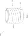
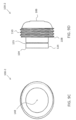
- FIG. 1 illustrates one example of an ICP monitoring device 100-1 includes a housing 102 extending from a distal end 104 to a proximal end 106.
- housing 102 has a circular cross-sectional area as best seen in FIGS. 1 , 5 and 6 and is formed from a metal such as, for example, titanium, stainless steel, gold, silver, or other biocompatible metal.
- a metal such as, for example, titanium, stainless steel, gold, silver, or other biocompatible metal.
- a portion of the exterior surface 108 of housing 102 includes self-tapping threads 110 for securing ICP monitoring device 100 to the skull of a patient.
- the exterior surface 108 of housing 102 does not include threads and is instead coupled to the skull of a patient via a press fit and/or through the use of one or more outwardly extending tabs 103-1, 103-2, 103-3, 103-4 (collectively "tabs 103") each defining a respective hole 105-1, 105-2, 105-3, 105-4 (collectively "holes 105") for receiving a screw, which is used for securement.
- tabs 103 and holes 105 are illustrated in FIG. 5 , one of ordinary skill in the art will understand that the number of tabs 103 and holes 105 may be greater than or less than four.
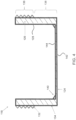
- Housing 102 defines an internal chamber 112 ( FIG. 2 ) in which a printed circuit board ("PCB") 114 is disposed.
- PCB printed circuit board
- housing 102 includes a proximal component 116 that is coupled to a distal component 118.
- proximal component 116 includes a chamber sealing wall 120 from which a circular side wall 122 extends in a first direction.
- Distal component 118 which is best seen in FIGS. 2 and 4 , includes a bottom wall 124, which defines a fixed-edge diaphragm as described in greater detail below, from which circular side wall 126 extends.
- Proximal component 116 and distal component 118 are coupled together to provide a hermetic seal such that chamber 112 has an internal pressure, which is known.
- chamber 112 has a pressure that is lower than all anticipated pressures expected to be exerted on bottom wall 124 during normal operating conditions when ICP monitoring device 100-1 is implanted in a skull of a patient. Sealing chamber 112 at a known pressure that is lower than expected operating pressures mitigates the possibility of an effect known to those of ordinary skill in the art as "oil-canning," in which a transition from concave to convex conformations, or vice versa, induces erroneous gauge readings and signal noise.
- chamber 112 is filled during manufacturing with a gas such as Argon, Helium, or other combination of gases.
- chamber 112 is filled with an electrically insulating liquid or is evacuated prior to sealing.
- the effect of controlling the contents of the sealed chamber 112 is to create a reference pressure against which the degree of deformation of the fixed-edge diaphragm may be measured in order to correlate to an external pressure experienced by the diaphragm. Controlling the contents of sealed chamber 112 also controls and defines the characteristic pressure changes in the chamber contents, which affects the gauges and pressure readings as the temperature changes.
- the internal surface 128 of side wall 122 of proximal component 116 defines one or more threads 130 that are configured to engage one or more threads 132 disposed on the external surface 134 of side wall 126 of distal component 118.
- threads 132 are formed on a first portion 136 of side wall 126 that is less than an entire length of side wall 126 such that portion 138 is unthreaded. Portion 138 is left unthreaded to isolate fixed-edge diaphragm 124 from heat and stress concentrations induced during the threading process.
- Bottom wall 124 which defines the fixed-edge diaphragm, comprises an impermeable, sealed diaphragm that is configured to interface with the dural sac, pial layer, brain parenchyma, or cerebro spinal fluid as described below.
- a ridge 140 extends between and forms the interface between side wall 126 and bottom wall 124. Ridge 140 extends at a non-perpendicular angle with respect to side wall 126 and bottom wall 124 to change the stress concentrations as described below.
- the thickness of bottom wall 124 is between 0.004 inches and 0.005 inches, although one of ordinary skill in the art will understand that bottom wall 124 may have other thicknesses.
- the thickness of side wall 126 may be varied although it should be sufficiently thick to withstand stresses from manufacturing and induced stress from being under pressure in situ.
- the external surface 142 of bottom wall 124 which forms the diaphragm, is electro-polished or coated with materials or drugs known to prevent scar tissue overgrowth. Fibrous tissue overgrowth occurs within several weeks of implantation of foreign material into the body. While the formation of scar tissue overgrowth is a normal part of the body's physiological healing response, it is typically undesirable as it can affect pressure transmission across diaphragm 124. Additionally, contraction of such scar tissue can artificially deform or generate pressures on the diaphragm.
- Examples of materials that may be deposited on external surface 142 include, but are not limited to, polyvinylpyrrolidone ("PVP"), phosphoryl colene, polyethylene oxide (“PEO”), hydro-gels, and paralene, to name a few possible materials.
- Examples of drugs that may be disposed on the external surface 142 of bottom wall 124 includes, but are not limited to, anti-inflammatory agents, cell cycle inhibitors, anti-platelet agents, anti-thrombin compounds, and thrombolytic agents.
- External surface 142 is fabricated to provide a flat surface.
- a flatter diaphragm 124 is less compliant and thus the electrical changes induced in gauges 146 mounted on the diaphragm 124 will have a higher gain than from a less flat diaphragm.
- a flat diaphragm minimizes the dampening effects of tissue overgrowth by enabling more sensitive gauge measurements.
- strain gauges 146 may be connected to bottom wall 124 using an epoxy or other securement material or means.
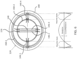
- four strain gauges are implemented with one pair of strain gauges 146-2, 146-3 being aligned in parallel near the center 148 of bottom wall 124 and the other pair of strain gauges 146-1, 146-4 are disposed in parallel with one another adjacent to one another and perpendicular to gauges 146-2, 146-3.
- parallel gauges 146-1 and 146-4 are disposed farther way from center 148 than gauges 146-2 and 146-3, which are disposed perpendicular to gauges 146-1 and 146-4.
- the center 148 of diaphragm 124 experiences a higher tangential strain compared to the outer edge 140, which experiences a higher radial strain of opposite polarity.
- potential drift of resistive-based pressure sensors comes from a number of sources that alter the physical properties of the gauge 146, which causes net electrical characteristics of the gauge elements 146, e.g., resistance, to change in an unpredictable fashion. These sources include deterioration of the gauges, warping or fatigue of the sensor, and a gradual breakdown of the adhesive used to attach the gauges to the sensor.
- An extended ridge diaphragm advantageously allows for the ends of the semiconductor strain gauges 146 to be placed along two neutral axes where zero strain, or close to zero strain, is experienced. A neutral axis arises at transition point from compressive to tensile stress as shown in FIG. 6 .
- the diaphragm 124 By extending a peripheral ridge 140 upon the outside edge of the diaphragm 124 (approximately 1/10th the radius of the diaphragm), the diaphragm 124 effectively includes two neutral axes where strain is negligible as shown in the lower portion of FIG. 6 . Placing the ends of the semiconductor gauges 146 along the two neutral axes provides enhanced stability and durability.
- the two radial strain gauges 146-1, 146-4 are oriented 90 degrees from each other instead of 180 degrees as illustrated in FIG. 6 . Such arrangement results in partial cancellation of forces induced on the sides of the diaphragm 124.
- the thickness of the epoxy used to attach gauges 146 to diaphragm 124 can be minimized to reduce the amount of viscoelastic drift caused during normal usage, particularly when a constantly elevated pressure is exerted on the diaphragm as in the human body.
- a silicon dioxide or other insulating layer is grown on the bottom of the strain gauges 146 or on inner surface 144 of diaphragm 124 such that the adhesive employed need not be thick enough to serve as the only insulating element.
- strain gauges 146 are coupled to contact blocks 152, which may be disposed on interior surface 154 of side wall 126 of distal component 118.
- the coupling between strain gauges 146 and contact block 152 is provided by wires 156.
- Wires 156 also connect contact block 152 to PCB 114 as illustrated in FIG. 2 .
- contact block 152 is omitted and wires directly connect strain gauges 146 to PCB 114.
- Strain gauges 146 are electrically connected to form a full Wheatstone bridge 158 as illustrated in FIG. 7 .
- strain gauge 146-1 is coupled to strain gauge 146-2 at node 160, which serves as a first output node of Wheatstone bridge 158.
- Strain gauge 146-1 is also coupled to strain gauge 146-3 at node 162, which receives a positive voltage from a first voltage source 164 through resistor 166.
- Strain gauge 146-3 is coupled to strain gauge 146-4 at node 168, which serves as a second output node for Wheatstone bridge 158.
- Strain gauges 146-4 and 146-2 are coupled together at node 170, which is coupled to a low voltage power supply such as ground.
- nodes 162 and 170 may be coupled to other supply voltages and that positive and negative do not necessarily have a physiological meaning in connection with ICP.
- FIG. 8 illustrates some of the circuitry that may be formed on PCB 114.
- the circuitry formed on PCB 114 may include discrete components and/or be formed in an integrated circuit ("IC") or packaged together as an application specific integrated circuit (“ASIC").
- a low-drift differential amplifier 172 receives signals from nodes 160 and 168 of Wheatstone bridge 158 and outputs a signal to a microprocessor 174, which is configured with an analog-to-digital converter (“ADC").
- ADC analog-to-digital converter
- the ADC is a discrete component separated from microprocessor 174.
- Microprocessor 174 is in signal communication with a non-transient computer readable storage medium 176, such as a random access memory (“RAM”), a flash memory, or other storage device, and with a communication module 178 configured for radio frequency (“RF”) communication or communication using other frequencies.
- a non-transient computer readable storage medium 176 such as a random access memory (“RAM”), a flash memory, or other storage device
- a communication module 178 configured for radio frequency (“RF”) communication or communication using other frequencies.
- RF radio frequency
- RF communication module 178 is coupled to an antenna 180 configured to transmit and receive wireless signals.
- communication module 178 is configured to communicate using Bluetooth, Near-Field Communication, or other communication protocol for near or distant communication.
- communication module 178 is a transceiver configured to transmit and receive signals in an unregulated band, such as the 2.4 GHz frequency band.
- unregulated band such as the 2.4 GHz frequency band.
- Additional circuitry may also be disposed on PCB 114 for enhanced data gathering.
- a gyroscope 182, an accelerometer 184, both, or another device for determining an orientation of ICP monitoring device 100 relative to a vertical direction or axis are disposed on PCB 114.
- the gyroscope and/or accelerometer may be single-or multi-axis devices manufactured using MEMS technology. These devices 182, 184 are utilized to determine the orientation of the patient's head, which affects the measured ICP as will be understood by one of ordinary skill in the art.
- a patient's ICP will be higher when supine, e.g., perpendicular to the vertical direction or axis, than when sitting upright (e.g., parallel to the vertical direction or axis), due to the effect of gravity on the patient's cerebral spinal fluid ("CSF").
- CSF cerebral spinal fluid
- gyroscope 182 and/or accelerometer 184 are configured for use in long-term sensor implantation scenarios to monitor a patient's orientation.
- devices 182 and 184 can be used to detect a patient falling and cause microprocessor 174 to record the time of the fall for later correlation with a rise in ICP.
- the detection of a fall will trigger an alert to the patient, primary caregiver, or emergency services based on a rise in ICP associated with a fall.
- Patient orientation is also useful in determining and recording when the patient is awake or asleep. For example, diagnostic measurements for normal pressure hydrocephalus are typically obtained when a patient is sleeping.
- Microprocessor 174 can be programmed to obtain such measurements when gyroscope 182 and/or accelerometer 184 provide signals to microprocessor 184 identifying that the patient is lying down. In some embodiments, such measurements are only recorded after it is determined the patient has been lying down for a period of time that exceeds a threshold, e.g., 10 minutes, 20 minutes, etc.
- a threshold e.g. 10 minutes, 20 minutes, etc.
- the electronics disposed on one or more PCBs 114 are powered by a power supply 186.
- power supply 186 includes a battery while in other embodiments the electronics are powered by another power supply.
- the electronics disposed on PCB 114 can receive power via inductive coupling between a coil antenna 188 in or on top of the implant and another coil antenna in or outside of an external unit as described in greater detail below.
- Each of these coil antennas make up a portion of a resonant circuit that includes inductors, capacitors, and resistors such that the circuit is electrically resonant at a predetermined frequency.
- a powered resonant circuit brought into the vicinity of a circuit resonant at a close frequency or a harmonic will inductively couple with the second circuit thereby inducing a current to flow.
- This current can be used to run the implanted electronics or charge a capacitor of power supply 186 that stores energy for powering the electronics disposed on PCB 114.
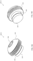
- ICP monitoring device 100-2 includes a housing 102 extending from a distal end 104 to a proximal end 106.
- housing 102 has a circular cross-sectional area as best seen in FIGS. 9C and 9D and is formed from a metal such as, for example, titanium, stainless steel, gold, silver, or other biocompatible metal.
- the exterior surface 108 of proximal portion 116 of housing 102 includes self-tapping threads 110 for securing ICP monitoring device 100-2 to the skull of a patient.
- Distal portion 118 of housing 102 includes a smooth outer surface 134 having an outer diameter that is smaller than an outer diameter of proximal portion 116 enabling distal portion 118 to pass through the inner dimension of the ridge of bone created by an anti-plunge cranial perforator as will be understood by one of ordinary skill in the art.
- housing 102 and the burr hole created by such drilling mechanism are complementary such that CSF is prevented from leaking through the burr hole around housing 102.
- a circumferential trough 135 is formed along the length of distal portion 118 as can be seen in FIGS. 9A, 9B and 9D .
- Trough 135 advantageously isolates fixed-edge extended-ridge diaphragm 124 and strain gauges 146 from stresses and strains afflicted on the housing during implantation. Such stresses and strains can deform diaphragm 124 and cause damage or measurement drift.
- strain gauges 146 are affixed to bottom wall 124, which forms the fixed-edge diaphragm, by epoxy or other means.
- strain gauges 146 can be disposed on bottom wall 124 such that strain gauges 146-2, 146-3 are aligned in parallel with one another near the center of bottom wall 124 and the other pair of strain gauges 146-1, 146-4 are disposed in parallel with one another adjacent to one another and perpendicular to gauges 146-2, 146-3.
- Extended ridge 140 extends at a non-perpendicular angle with respect to side wall 126 and bottom wall 124 to change the stress concentrations as described above.
- the thickness of the epoxy used to attach gauges 146 to diaphragm 124 can be minimized to reduce the amount of viscoelastic drift due to long-term variations in average pressure, due to, for example, a patient traveling to a higher or lower altitude.
- a silicon dioxide or other insulating layer is grown on the bottom of the strain gauges 146 or on inner surface 144 of diaphragm 124 such that the adhesive employed need not be thick enough to serve as the only insulating element.
- Side wall 126 extends from bottom wall 124 to interface 117 where distal portion 118 is joined to proximal portion 116.
- Proximal portion 116 defines a recessed area 119 that houses PCB 114 on which the electronics are disposed. Silicon potting or other biocompatible material disposed in recessed area 119 over PCB 114 and the electronics disposed thereon. The shape formed by the potting is designed to minimize the potential for skin necrosis around the implant's external proximal end. Placing PCB 114 and the electronics in recessed area 119 reduces the interference of the housing material on the function of the electronics, particularly the coil antenna.
- Proximal portion 116 also defines an engagement feature 121 that is configured to receive or engage a tool for aiding in insertion of ICP monitoring device 100-2 into a skull of a patient.
- engagement feature 121 is configured to receive a tool having a hexagonal cross-sectional area, although one of ordinary skill in the art will understand that engagement feature 121 may be complementary to tools having other cross-sectional geometries including, but not limited to, stars and squares.
- proximal portion 116 and distal portion 118 are formed from a single piece of a rod. In some embodiments, proximal portion 116 and distal portion 118 are coupled together at interface 117 by laser welding or screw threads. In some embodiments, a ceramic feedthrough is brazed to side wall 126 and to proximal portion 116 to join proximal portion 116 to distal portion 118 at interface 117 and to allow wires 156 to pass from chamber 112 defined by distal portion 118 to recessed area 119 defined by proximal portion 116.
- Proximal portion 116 and distal portion 118 are coupled together to provide a hermetic seal such that chamber 112 has a known internal pressure.
- chamber 112 can be filled during manufacturing with a gas such as Argon, Helium, or other combination of gases.
- chamber 112 is filled with an electrically insulating liquid or is evacuated prior to sealing.
- the effect of controlling the contents of the sealed chamber 112 is to create a reference pressure against which the degree of deformation of the fixed-edge diaphragm may be measured in order to correlate to an external pressure experienced by the diaphragm 124.
- controlling the contents of sealed chamber 112 also controls and defines the characteristic pressure changes in the chamber contents, which affects the gauges and pressure readings as the temperature changes.
- the external surface 142 of bottom wall 124 which forms the diaphragm, is electro-polished or coated with materials or drugs known to prevent scar tissue overgrowth. Fibrous tissue overgrowth occurs within several weeks of implantation of foreign material into the body.
- materials that may be deposited on external surface 142 include, but are not limited to, polyvinylpyrrolidone ("PVP"), phosphoryl colene, polyethylene oxide (“PEO”), hydro-gels, and paralene, to name a few possible materials.
- PVP polyvinylpyrrolidone
- PEO polyethylene oxide
- hydro-gels hydro-gels
- paralene to name a few possible materials.
- drugs that may be disposed on the external surface 142 of bottom wall 124 includes, but are not limited to, anti-inflammatory agents, cell cycle inhibitors, anti-platelet agents, anti-thrombin compounds, and thrombolytic agents.
- External surface 142 is fabricated to provide a surface that is as flat as possible. As described above, a flatter diaphragm 124 is less compliant and thus the electrical changes induced in gauges 146 mounted on the diaphragm 124 will have a higher gain than from a less flat diaphragm. Thus, a flat diaphragm minimizes the dampening effects of tissue overgrowth by enabling more sensitive gauge measurements.
- Strain gauges 146 are coupled to PCB 114 via wires 156 and are electrically connected to form a full Wheatstone bridge 158 as illustrated in FIG. 7 .
- FIG. 11 illustrates one example of a circular PCB 114 having a circular cutout 115.
- PCB is sized and configured to be received within recess 119 on which circuitry is formed. Locating PCB 114 in recess 119 isolates the electronics disposed on PCB 114 from chamber 112 to mitigate the effects of the housing 102 on the inductive coupling between housing 102, antenna 180, and coil 188.
- a low-drift differential amplifier 172 receives signals from nodes 160 and 168 of Wheatstone bridge 158 and outputs a signal to a microprocessor 174, which is configured with an ADC.
- Microprocessor 174 is in signal communication with a non-transient computer readable storage medium 176, such as a RAM, a flash memory, or other storage device, and with a communication module 178 configured for wireless communication.
- a non-transient computer readable storage medium 176 such as a RAM, a flash memory, or other storage device
- a communication module 178 configured for wireless communication.
- Other circuitry for performing analog/digital filtering, analog/digital smoothing, frequency analysis, and time domain operations can be disposed on PCB 114.
- PvF communication module 178 is coupled to an antenna 180 configured to transmit and receive wireless signals.
- communication module 178 is configured to communicate using Bluetooth, Near-Field Communication, or other communication protocol for near or distant communication.
- communication module 178 is a transceiver configured to transmit and receive signals in an unregulated band, such as the 2.4 GHz frequency band.
- unregulated band such as the 2.4 GHz frequency band.
- a gyroscope 182 and/or an accelerometer 184 are disposed on PCB 114.
- the gyroscope and/or accelerometer may be single- or multi-axis devices manufactured using MEMS technology. These devices 182, 184 are utilized to determine the orientation of the patient's head, which affects the measured ICP as will be understood by one of ordinary skill in the art. For example, a patient's ICP will be higher when supine than when sitting upright or standing upright, due to the effect of gravity on the patient's CSF.
- gyroscope 182 and/or accelerometer 184 disposed on PCB 114 may be utilized to determine and/or identify medically relevant events such as, for example, a patient falling.
- Devices 182, 184 can be used to record the force with which the fall impacted the patient's skull and be correlated with changes in ICP before, during, and/or after the event to determine various causes and effects of the event as well as aid in medical diagnosis and/or treatment.
- the improved ICP monitoring devices 100-1, 100-2 (“ICP monitoring devices 100") described above may be installed at various locations in the skull 10 of a patient.
- an ICP monitoring device 100 is installed at Frazier's Point 12 or in Kocher's Point 14 in a skull as illustrated in FIG. 12A .
- the method of installing an ICP monitoring device 100 in a skull 10 of a patient is described with reference to FIGS 12A and 12B .
- the skin 20 and fascia 22 are removed from the insertion side to expose the patient's skull 10 as best seen in FIG. 12B .
- the insertion site may be at the Frazier's Point 12 located 3 cm lateral to the midline and 6 cm superior to the inion, the Kocher's Point 14 located 11 cm posterior to the nasion and 2.5 cm lateral to midline, or at another location as will be understood by one of ordinary skill in the art.
- ICP monitoring device 100 both above or below the tentorium at locations commonly used positions for placement of intraventricular catheters.
- a cranial burr hole is made in a patient's skull 10 by a surgeon using an anti-plunge cranial perforator, a drill, or other tool.
- the hole is made by the surgeon to expose the dural sac 24 surrounding the brain 26 of the patient.
- ICP monitoring device 100 is then inserted into the hole formed in the skull 10 as illustrated in FIG. 12B .
- housing 102 is threaded into skull bone 10 such that self-tapping threads 110 dig into skull bone 10 as ICP monitoring device 100 is rotated.
- an adapter grommet (not shown) defining a central passageway sized and configured to receive ICP monitoring device 100 is first inserted to cranial burr hole.
- the adapter grommet may have a cross-sectional area that is complementary to the cranial burr hole formed in the patient's skull 10.
- proximal portion 116 may have an outer diameter that is greater than a diameter of cranial burr hole such that distal portion 118 is received within the hole and proximal portion 116 abuts the outer surface of skull bone 10.
- Tabs 103 may outwardly extend from proximal portion 116 and each define an opening 105 sized and configured to receive screws that assist in affixing ICP monitoring device 100 to skull 10.
- ICP monitoring device 100 The depth to which ICP monitoring device 100 is installed may be varied. For example, ICP monitoring device 100 is installed such that diaphragm 124 is disposed flush with or slightly below the inner table of the skull such that diaphragm 124 contacts dura 24.
- diaphragm 124 is positioned below a fenestrated dural layer such that diaphragm 124 is in contact with the pial layer or brain parenchyma tissue. Such positioning may provide for improved sensitivity to monitoring as well as reducing and/or eliminating impedance due to the dura matter.
- a surgeon may be notified that ICP monitoring device is properly positioned by device 100 generating a signal from gauges 146 in response to diaphragm 124 contacting dura 24. The signal may be received by an external unit (described below), which signals the surgeon installing monitoring device 100 by emitting an audio and/or visual indication.
- Monitoring device 100 can also collect data during the installation process concerning stress and strain on side wall 126.
- strain gauges 146 can generate signals identifying detected strain on housing 124 while the ICP monitoring device 100 is being twisted into skull 10. In such a configuration, ICP monitoring device 100 can alert the surgeon if excessive strain is detected. Excessive strain during implantation may be a marker of improper implantation and may lead to inaccurate pressure readings due to diaphragm deformation.
- an ICP monitoring device 100 is implanted in a patient at block 1902.
- a pressure reading is taken and assessed to determine the quality of the contact of ICP monitoring device 100 and the intracranial pressure region.
- the pressure reading taken by ICP monitoring device 100 may be transmitted to an external device, such as an external device 300, 400, 500 described in greater detail below, such that a user may be able to assess the quality of the implant.
- ICP monitoring device 100 is properly implanted.
- an external device may display a graphical representation of an ICP waveform to a user on a display such that the user may assess whether or not the ICP monitoring device is properly implanted.
- ICP monitoring device is placed in a mode in which it assesses the pressure signals to determine whether implantation has been properly made.
- processor 174 of ICP monitoring device receives the sensed signals from strain gauges 146 and determine a peak-to-peak signal voltage to determine whether sufficient contact has been made between diaphragm 124 and the intracranial surface of a patient. If it is determined that implantation was not successful, e.g., the contact between diaphragm 124 and the intracranial pressure surface of a patient is not sufficient to detect pressure accurately, then the implantation procedure at block 1902 is performed again.
- method 1900 proceeds to block 1908 where a plurality of calibration readings are recorded at different elevations.
- the patient can be positioned in a supine position with their head flat, which may be recorded as a zero degree elevation.
- ICP monitoring device 100 stores the pressure waveform for a predetermined period of time as well as a position measurement that corresponds to signals received from gyroscope 182 and/or accelerometer 184.
- the patient can be elevated to 30 degrees, 60 degrees, 90 degrees, and other positions and ICP monitor 100 can record the pressure waveform for the predetermined period of time along with the values measured by gyroscope 182 and/or accelerometer 184 associated with this position.
- the patient can be positioned in a completely upright, or standing, position and ICP monitoring device 100 can record the waveforms received from strain gauges 146 along with the values measured by gyroscope 182 in these positions.
- processor 174 may read values from gyroscope 182 and store the values in non-transient computer readable storage 176.
- ICP values are calculated for each of the different positions at which the patient was positioned.
- the ICP values are calculated based on the stored waveforms and are recorded with the position data.
- the calculated ICP value is compared to a measured ICP value to determine if ICP monitoring device has been calibrated. For example, if the calculated ICP value is not equal to the measured ICP value, then ICP monitoring device 100 is not calibrated. If the ICP value is equal to the measured ICP value, then ICP monitoring device 100 is calibrated and method 1900 is finished at block 1922.
- a lumbar drain is inserted into patient.
- a lumbar drain is typically a flexible, soft plastic tube that is inserted into the lower back of a patient to remove CSF.
- the tube can be coupled to a drainage bag for capturing the removed CSF.
- the pressure is transduced with a patient in a zero degree position.
- the lumbar drain is coupled to a pressure transducer that is calibrated to zero at the level of the patient's tragus, which is used as the common reference point by physicians for ICP monitoring.
- the pressure is transduced with a patient undergoing a Valsalva maneuver.
- the Valsalva maneuver can be performed in various ways. One way is to have the patient close his/her airway, e.g., closing his/her mouth and pinching his/her nose closed, and trying to exhale to increase intrathoracic pressure. In this method, the patient can exhale against a pressure recording device such as a manometer, which can record the intrathoracic pressure. Another way to induce a Valsalva is to have the patient bear down as if having a bowel movement. The Valsalva maneuver increases intrathoracic pressure, thereby decreasing venous outflow from the brain and increasing intracranial pressure. Performing Valsalva maneuvers while the patient is supine allows for measurement of a range of intracranial pressures and waveforms with each Valsalva.
- conversion parameters are adjusted based on the recalibration procedures performed at blocks 1916 and 1918.
- adjustable parameters include, but are not limited to, the raw voltage reading of the Wheatstone bridge 158 when the patient is at various elevations, a calculated line or curve of best fit between various Wheatstone bridge voltage readings, the raw voltage reading of the gyroscope 182 or accelerometer 184 at various elevations (to account for, e.g., implantation that is not perfectly level), and various calculated waveform parameters at various patient elevations as described below.
- calibration method 1900 is described as being performed when ICP monitoring device has been implanted, one of ordinary skill in the art will understand that the calibration can be conducted while the sensing diaphragm is exposed to air prior to implantation or when ICP monitoring device 100 is disposed within a shallow depth of fluid.
- the calibrated ICP monitoring device 100 is configured to sense and store data concerning intracranial pressure as detected by strain gauges 146.
- a measure of pressure can be derived from a computed correlative relationship between sensormeasured pressure and a number of waveform features.
- a correlative relationship can include any relationship, such as a formula, a graph, a curve, a linear relationship, a non-linear relationship, a neural network, a classifier, or any other relationship that provides a value of one variable when presented with a value of another variable or variables.
- strain gauges 124 The processing of the signals received from strain gauges 124 is described with reference to FIG. 20 .
- Mechanical strains on diaphragm 124 are sensed by strain gauges 146, which generate electrical analog signals in response. These analog signals are digitized at block 2002 by an ADC, such as an ADC of processor 174 or a separate ADC.
- the digitized voltage are processed to generate an ICP waveform, such as the ICP waveform illustrated in FIG. 13 .
- the digitized voltages are converted to a characterized waveform in a fixed method, and in some embodiments, the digitized voltages are converted to a characterized waveform in a dynamic method as will be understood by one of ordinary skill in the art.
- the ICP waveform includes three peaks (PI, P2, P3).
- an ICP value is calculated based on the waveform using a linear, quadratic, or other approximation method.
- the values derived from the waveform features can be selected from a group of parameters for each peak including amplitude, rate of ascent, and rate of descent, among others. Additionally, timing of any of the aforementioned waveform features can be taken with respect to the cardiac or respiratory cycle or timing of another ICP waveform feature.
- a phase shift can also be calculated between the waveform of both the intracranial pressure and blood pressure waveforms which also serve as an index of intracranial pressure, intracranial compliance, or another physiological parameter.
- Processor 174 can be configured to identify initial waveform feature indices and correlations between these indices can be captured from various sensor modalities after implantation in a patient. Processor 174 can also be configured to compare current real-time waveform features to an initial set of reference calibration features established for the various sensor modalities enables the detection of either a physiological condition or an improper calibration of the ICP monitoring device.
- a library of patient waveform data acquired from multiple patients and time points across a number of sensor modalities can be stored in non-transient computer storage 176.
- the measured waveforms are compared to waveforms in a waveform library stored in non-transient computer storage 176.
- Processor 174 determines whether there has been a change in a physiological condition of a patient, sensor baseline drift, or improper calibration of a sensor through this comparison. For example, if a difference between current real-time waveform and an ICP value stored in non-transient computer storage 176 corresponding to a same position is above a threshold value, then an error signal is generated notifying a patient or caretaker of a problem that there is a problem with the sensor.
- the data can be stored by ICP monitoring device 100 and/or transmitted to an external device 200, 300, 400, 500 for displaying the ICP measurement to a user.
- Processor 174 is also configured to correlate measured pressures to changes in non-invasive measurements. Such measurements include, but are not limited to, carotid artery pressure waveforms, peripheral artery pressure waveforms, tonometry, MRI scanning algorithms, acoustic emissions, visual evoked potentials, transracial Dopplers, ultrasonic resonance, and skull pulsations.
- carotid artery pressure and peripheral artery pressure waveforms are used to analyze impedance changes in the carotid waveform attributable to intracranial impedance.
- processor 174 uses processor 174 to characterize intracranial impedance which can be correlated to measured pressure to determine actual pressure.
- processor 174 is also configured to correlate or calibrate measured pressure against an invasive measurement of pressure such as pressure measured through a lumbar drain, an omaya reservoir, a ventricular catheter, cerebrospinal fluid shunt, or a vascular catheter in a vein or artery.
- processor 174 is configured to analyze a number of waveform features to provide information regarding the condition of the patient. Such conditions include, but are not limited to, a change in intracranial pressure, intracranial compliance, oxygenation, heart rate, temperature, respiratory rate, carotid pressure waveform, peripheral artery waveform, or in cerebral perfusion pressure. Algorithms utilizing a number of the waveform features or relations are stored in non-transient computer storage 176 for execution by processor 174. In some embodiments, the algorithms executed by processor 174 are used for the prediction of rises in ICP, diagnosis of acute stroke, tool for improved accuracy in diagnosis of normal pressure hydrocephalus, or assessing the responsiveness to a treatment aimed at changing intracranial compliance. Algorithms can include a number of mathematical functions or experimentally validated relationships, heuristic algorithms, transfer functions, statistical models, or deterministic models.
- the waveform analyses described above may be performed by a processor separate from processor 174 after the data acquired by ICP monitoring device 100 is transmitted to an external unit.
- the electronics of ICP monitoring device 100 are configured to permit bidirectional transmission of data such that data may be received from and transmitted to an external device.
- data is transmitted from ICP monitoring device 100 to a separate device via an inductive coupling link.
- Data is sent by modulating a property of a resonant circuit, which may be coupled to or included in communication module 178 and/or antenna 180, in such a way so as to induce a detectable current change on the other end of the inductive coupling link.
- the modulation may be such that data transmitted is frequency shifted, phase shifted, etc.
- the circuitry connected to the resonant circuit is designed to filter out the carrier frequency at which the inductive coupling resonates, leaving just the data waveform, which may be decoded by digital electronics and interpreted in embedded software as will be understood by one of ordinary skill in the art.
- antenna 180 may be a separate antenna from inductive coupling link, which, when matched with appropriate circuitry, enables ICP monitoring device 100 to transmit data as will be understood by one of ordinary skill in the art.
- An external unit can send commands over the inductive coupling link or separate antenna to the implanted electronics to program or select in which of several modes the processor 174 is to operate. Examples of such operating states include, but are not limited to, reprogramming, calibrating, streaming data for a predetermined amount of time, and long-term standalone operation.
- a long-term, standalone monitoring operation is an operation in which the external device or unit is to be removed and ICP monitoring device 100 continues to record or sense ICP data.
- the circuit elements disposed on PCB 114 operate in a state of minimal power draw, which uses a low-power timing circuit to alternate between powering off and powering on some subset of the modules in the electronics.
- processor 174 may periodically receive sensed signals from strain gauges 146 and store the data in storage 176. When not acquiring data, processor 174 may turn off one or more of gyroscope 182, accelerometer 184, communication module 178, ADC, on-board electronic components including electronic timers or clock modules, and other integrated circuits as will be understood by one of ordinary skill in the art.
- the recorded data can be transmitted to an external unit in response to receiving a trigger signal from the external unit or at a preprogrammed time.
- FIG. 14 illustrates one example of a hand-held device 200 configured to transmit and receive data and control signals from ICP monitoring device 100.
- Hand-held device 200 includes a housing 202 comprising a transmission end 204 and a handle 206 disposed opposite and coupled to transmission end 204.
- Handle 206 of housing 202 can be at least partially hollow such that a replaceable or rechargeable power supply can be stored therein.
- replaceable or rechargeable batteries can be stored in handle 206 of housing 202 for powering a communication unit disposed within 204.
- Rechargeable batteries can be recharged by plugging the hand-held unit into a wall outlet via a micro-USB or other physical interface such as a holster that includes metal charging prongs.
- transmission end 204 of device 200 can include a speaker and/or one or more light emitting diodes ("LED") for providing an audible and/or visual notification to a user that identifies when data is successfully transmitted to or received from ICP monitoring device 100.
- LED light emitting diodes
- a single beep may be emitted from a speaker when data is successfully read from and/or transmitted to ICP monitoring device 100, and multiple beeps may be emitted from the speaker when there is an error transmitting or receiving data.
- a green LED may light up when data is correctly transmitted
- a red LED may light up when data an error occurs during transmission.
- device 200 may emit an audible beer or turn on a colored LED to inform the user that the ICP monitoring device 100 has been properly implanted, which may be determined by the ICP monitoring device 100 transmitting an acceptable ICP waveform and/or determining when physical contact has been made with the dura matter, pia matter, or parenchyma.
- Other methods of providing user feedback such as a device for vibrating hand-held device 200, may be disposed within and supported by housing 202.
- FIGS. 14 , 15, and 16 illustrate other possible implementations of external devices 300, 400, 500 that may be used in connection with ICP monitoring device 100.
- ICP monitoring device 100 is coupled to an external device 300 by a wire 302.
- External device 300 is configured as an ear piece and is sized and configured to be at least partially received in the ear concha or canal.
- external unit 400 is configured as an ear piece that is configured to fit behind a patient's ear.
- Unit 400 is coupled to ICP monitoring device 100 via wire 402, which may include a resonant circuit and coil for inductive coupling with coil 188 disposed on PCB 114.
- wire 402 may include a resonant circuit and coil for inductive coupling with coil 188 disposed on PCB 114.
- external unit 500 is placed directly on the scalp overlying the ICP monitoring device 100. External unit 500 can be secured down with an adhesive or an anchoring stitch.
- an external unit can be integrated into a headband that fits circumferentially around the head.
- the headband can include or more inductive coils such that the orientation of the headband is not crucial to the transmission of power to the implanted ICP monitoring device 100.
- Other head- worn embodiments include hats.
- the external device can also be implemented as another worn garment such as a necklace.
- a smartphone or computer peripheral may also be configured as an external device, with an inductive coupling link (i.e., a near-field communication ("NFC") coil) or a 2.4 GHz transceiver (i.e., a Bluetooth transceiver or chip) built-in for powering and/or communicating with the ICP monitoring device 100.
- the external device need not be constantly inductively coupled to the ICP monitoring device 100. If the ICP monitoring device 100 is placed in a stand-alone mode as described above, the external device may either receive data periodically when the patient or primary caregiver places it within inductive coupling range, or may receive data more frequently via a longer-range communication protocol such as one implemented in the 2.4 GHz ISM band with a separate antenna 180.
- the external unit 200, 300, 400, 500 such unit may be used in an outpatient setting.
- the external unit is designed to be rugged and user-friendly, including pre-programmable alarms associated with parameters such as mean ICP, sensor baseline drift, and device failure.
- the external units 200, 300, 400, 500 are configured to record symptoms experienced by a patient including, but not limited to, faintness, a headache, a ringing in the ears, etc.
- the external units 200, 300, 400, 500 are configured to store these timestamped symptoms alongside the ICP data that were made at the time of the symptom recording in a non- volatile computer storage.
- the acquired data can be transmitted in real-time or at a later time to other devices as described in greater detail below.
- the external units 200, 300, 400, 500 can display the acquired data, the symptom onset time, and, optionally, the description overlaid on the graph of ICP recordings or derived parameters.
- Such functionality advantageously allows primary caregivers to correlate the onset of symptoms with certain ICP waveform characteristics, such as an increase in mean ICP.
- the external unit(s) 200 are capable of transmitting data over network(s) 700 such as, for example, a local area network ("LAN”), a wide area network ("WAN"), the Internet, an EDGE network, 3G, 4G LTE, or other network over which data can be transmitted.
- network(s) 700 such as, for example, a local area network (“LAN”), a wide area network (“WAN”), the Internet, an EDGE network, 3G, 4G LTE, or other network over which data can be transmitted.
- device 200 is configured to receive data from ICP monitoring device 100, as described above, and transmit the data to one or more servers 702 via network 700.
- device 200 receives data from ICP monitoring device 100 and transmits data to server 702 via network 700 or by first transmitting the data to a computer 704-1, which then transmits the data to server 702.
- the transmission of data from hand-held device 200 to computer 704-1 can be made via a wireless connection, via a wired connection using a USB connection or other tethered connection, or via an exchange of a memory device such as an SD card or other transferable memory device.
- ICP monitoring device 100 transmits raw data (i.e., unprocessed or uncorrected data) to server 702 via an external device 200, 300, 400, 500.
- Server 702 which is configured with one or more processors, stores the data in a computer readable storage and performs data processing including the identification one or more waveform features to provide information regarding the condition of the patient.
- Such conditions include, but are not limited to, a change in intracranial pressure, intracranial compliance, oxygenation, heart rate, temperature, respiratory rate, carotid pressure waveform, peripheral artery waveform, or in cerebral perfusion pressure.
- the waveforms can be used to predict rises in ICP, diagnose acute stroke, improve the accuracy in the diagnosis of normal pressure hydrocephalus, and/or assess the responsiveness to a treatment aimed at changing intracranial compliance.
- Server 702 is configured to be accessed by primary caregivers and/or device technicians to gauge both the status of patients with implants and the status of the implants themselves. Access to server 702 is made via network 702 from one or more computers 704-1, 704-2, ..., 704-n ("computers 704"), from a personal digital assistant ("PDA") 706, from a smartphone 708, and/or other device capable of accessing network 700 via a browser or other connection interface.
- PDA personal digital assistant
- Other examples of network-enabled devices that can access server 702 via network 700 include, but are not limited to, portable music players having Wi-Fi capabilities, tablets, televisions, and Blu-ray players to name a few other possibilities.
- the network access to server 702 is facilitated by a secure web interface via browser located on the network-enabled device.
- the network-enabled devices can be configured to function as a patient monitoring device.
- server 702 can transmit alarms and/or status updates via network 700 to one or more of the network-enabled devices 704, 706, 708.
- alarms and/or status updates can be transmitted using emails, text messages, automated phone calls, or other communication methods that will be apparent to one of ordinary skill in the art.
- the status updates and/or alarms can be displayed on a display or trigger an audio alert on the network-enabled devices 704, 706, 708 that function as a patient monitor.
- the network-enabled devices 704, 706, 708 can reside with the patient, the patient's caregiver, and/or a physician whom the patient might see in an outpatient clinic, urgent care center, or emergency room.
- network-enabled devices 704, 706, 708 that function as patient monitors are capable uploading data to and downloading data from server 702.
- Examples of data that can be transmitted from a network-enabled device includes, but are not limited to, a patient's physiological parameters, the number and identity of ICP monitoring devices 100 being monitored by the network-enabled device 704, 706, 708, and the software version running on the unit and/or the ICP monitoring unit 100.
- network-enabled devices 704, 706, 708 are configured to download software upgrades and historical data related to a patient's physiological parameters from server 702.
- Network-enabled devices 704, 706, 708 are also configured to optionally store data received from ICP monitoring unit 100 via external device 200, 300, 400, 500 and/or server 702 internally, or to transmit the downloaded data or data derived from the downloaded data to ICP monitoring unit 100 or server 702.
- Network-enabled devices 704, 706, 708 are configured with a processor capable of processing data received from ICP monitoring device 100 via an external unit 200, 300, 400, 500, data received from server 702, or some combination thereof, in certain ways to determine certain parameters for display to a user. These parameters may include an estimation of baseline sensor drift, mean ICP, ICP pulsatility, and other parameters. Devices 704, 706, 708 can display the parameters on the display of the device as a chart, numbers, graphs, annotations overlaid on graphs, or other visual presentation.
- network-enabled devices 704, 706, 708 are configured with a user input device, such as a keyboard, a touchscreen for displaying a virtual keyboard, a microphone for receiving audio instructions, camera, or other interface for receiving data from a user.
- a user can use the user input device to set one or more alarm thresholds related to certain physiological parameters, send commands to an external unit 200, 300, 400, 500 and/or an ICP monitoring device 100, create annotations to be overlaid on graphs of certain physiological parameters, to name a few non-limiting possibilities.
- the disclosed devices, methods, and systems advantageously enable the ICP of a patient to be monitored with improved accuracy and with improved intelligence.
- the incorporation of an accelerometer and/or gyroscope in an ICP monitoring device advantageously enables the ICP monitoring device to determine position-related events such as sleeping, falling, and running, to name a few possibilities. The detection of such position-related events can trigger alerts to caregivers and enables improved diagnostics to be performed on recorded data.
- the ICP monitoring device can be used to acquire diagnostic measurements for normal pressure hydrocephalus when it is determined that a patient is sleeping.
- Waveforms generated from acquired or sensed data can be used to derive actual physiological measurements including, but not limited to, pressure, tissue compliance, or oxygenation.
- pressure measurement may be achieved without having to extract the sensor for external calibration or use an externally connected pressure reference.
- having a calculated pressure derived from feature based analysis is beneficial in calibration and correction of an actual measured value. The difference between the derived value of pressure or other physiological parameter and the actual measured value can be calculated and the sensor can alert the user if the difference exceeds a specified error threshold, signaling that recalibration may be necessary.
- the present devices, systems, and methods can be embodied in the form of methods and apparatus for practicing those methods.
- the present devices, systems, and methods can also be embodied in the form of program code embodied in a non-transient, tangible media, such as USB flash drives, memory cards, CD-ROMs, DVD-ROMs, Blu-ray disks, hard drives, or any other non-transient machine-readable storage medium, wherein, when the program code is loaded into and executed by a machine, such as a computer, the machine becomes an apparatus for practicing the invention.
- the present devices, systems, and methods can also be embodied, at least partially, in the form of program code, for example, whether stored in a storage medium, loaded into and/or executed by a machine, or transmitted over some transmission medium, such as over electrical wiring or cabling, through fiber optics, or via electromagnetic radiation, wherein, when the program code is loaded into and executed by a machine, such as a computer, the machine becomes an apparatus for practicing the invention.
- program code When implemented on a general-purpose processor, the program code segments combine with the processor to provide a unique device that operates analogously to specific logic circuits.
Description
- The disclosed systems and methods relate to extradural pressure monitors for monitoring and storing values related to intracranial pressure. The disclosed devices can be implanted in a head of a patient for either short- or long-term monitoring. The transmission of stored or real-time data to an external device consists of a radio-frequency communication circuit in the device.
- Intracranial pressure rises in the settings of a number of acute insults to the brain including trauma, stroke, swelling, hemorrhage, and hydrocephalus. Currently there does not exist a wireless device that measures intracranial pressures reliably and safely. Such a device would improve monitoring in the hospital setting and would furthermore enable intracranial pressure monitoring in the outpatient setting.
- Existing intracranial pressure ("ICP") monitoring devices have significant shortcomings which make them impractical for stable and accurate monitoring of intracranial pressure for the long term. Most designs involve either externalization of a fluid column or tunneling a wire connection to an external monitor. As such methods leave an open tract between the external environment and the brain, the likelihood of infection is high.
- Additionally, existing ICP devices have significant technical shortcomings. For example, many ICP devices are centered around gauges having a capacitance that varies with pressure, which are measured or sensed by LC circuits having a resonance that varies with this capacitance change. This approach, however, typically suffers from a great deal of drift in the gage readings.
- Some designs involve measuring volume changes in a fixed amount of a trapped fluid, which, lacking adequate temperature compensation, make the device's readings subject to both bodily and environmental temperature changes. Additionally, previous designs' methods of transmitting data have been insufficient, as they have been slow, noisy, and inconsistent. One prior art device is shown in
US2009/203983 A1 , and discloses a burr hole assembly operating in cooperation with a brain stimulation system. The assembly having one or more sensors for monitoring a patient's clinical status. -
EP1508295 discloses an intracranial pressure monitoring device comprising a microelectronic device coupled to a pressure sensor having a diaphragm responsive to external pressure to form a contiguous chamber with a predetermined pressure. - The invention is defined in claim 1.
- An intracranial pressure monitoring device includes a housing defining a first internal chamber, a plurality of strain gauges disposed on an inner surface of a diaphragm defined by a wall of the first internal chamber, a device for generating orientation signals, and circuitry coupled to the plurality of strain gauges and to the device. The circuitry is configured to generate intracranial pressure data from signals received from the plurality of strain gauges, generate orientation data based on the orientation signals received from the device, and store the intracranial pressure data and the orientation data in a computer readable storage such that the intracranial pressure data and orientation data are associated with each other.
-
-
FIG. 1 is a front isometric view of one example of an intracranial pressure monitoring device. -
FIG. 2 is a cross-sectional view of the intracranial pressure monitoring device illustrated inFIG. 1 . -
FIG. 3 is a cross-sectional view of the proximal portion of the intracranial pressure monitoring device illustrated inFIG. 1 . -
FIG. 4 is a cross-sectional view of the distal portion of the intracranial pressure monitoring device illustrated inFIG. 1 . -
FIG. 5 is a bottom-side plan view of one example of an intracranial pressure monitoring device in accordance with some embodiments. -
FIG. 6 illustrates one example of a layout of strain gauges disposed on the sensing diaphragm of an improved intracranial pressure monitoring device. -
FIG. 7 illustrates one example of the electrical connections of the sensors illustrated inFIG. 6 . -
FIG. 8 illustrates one example of a printed circuit board and the circuitry disposed on the printed circuit board in accordance with the intracranial pressure monitoring device illustrated inFIG. 1 . -
FIGS. 9A-9D are various views of another example of an intracranial pressure monitoring device. -
FIG. 10 is a cross-sectional view of the intracranial pressure monitoring device illustrated inFIGS. 9A-9D . -
FIG. 11 illustrates one example of a circular printed circuit board and the circuitry disposed on the circular printed circuit board in accordance with the intracranial pressure monitoring device illustrated inFIGS. 9A-9D . -
FIG. 12 illustrates various places on a human skull at which the intracranial pressure monitoring devices may be positioned. -
FIG. 13 is a cross-sectional view of an intracranial pressure monitoring device installed within a skull of a patient. -
FIG. 14 is an isometric view of one example of a hand-held external unit configured to transmit data to and receive data from an intracranial pressure monitoring device in accordance withFIGS. 1 and9A-9D . -
FIG. 15 illustrates an example of an external unit configured to transmit data to and receive data from an intracranial pressure monitoring device in accordance withFIGS. 1 and9A-9D . -
FIG. 16 illustrates an example of an external unit configured to transmit data to and receive data from an intracranial pressure monitoring device in accordance withFIGS. 1 and9A-9D . -
FIG. 17 illustrates an example of an external unit configured to transmit data to and receive data from an intracranial pressure monitoring device in accordance withFIGS. 1 and9A-9D . -
FIG. 18 illustrates one example of a network-based patient monitoring system. -
FIG. 19 is a flow diagram of one example of a method of calibrating an ICP monitoring device in accordance with some embodiments. -
FIG. 20 is a flow diagram of one example of monitoring performed by an ICP monitoring device in accordance with some embodiments. - The disclosed intracranial pressure ("ICP") monitoring devices and methods advantageously enable the short- or long-term monitoring and storage of ICP data in an implanted monitor capable of transmitting this data to an external reader. The disclosed devices have improved drift characteristics and lower infection risks. The disclosed devices and methods enable performing statistical signal analysis on the measured ICP data for purposes of assisting the clinical diagnosis. The data acquired by the device can be transmitted via a fast, reliable, radio frequency communication circuit.
- The disclosed devices include low drift, matched semiconductor strain gauges, which transduce deflection in the sensing portion of the device. In some embodiments, the sensing portion of the device is a fixed-edge extended-ridge diaphragm constructed in such a way as to cause the strain in the diaphragm at the location of the ends of the strain gages to be optimal for their drift characteristics.
- In some embodiments, the devices are powered by a mechanism, such as a battery, by an inductive coil in combination with a capacitor, or both, which allows for maximum flexibility of operation. The device also conserves power by putting the microprocessor and peripheral electronics into low-power modes between measurements, reducing their overall power draw.
-
FIG. 1 illustrates one example of an ICP monitoring device 100-1 includes ahousing 102 extending from adistal end 104 to aproximal end 106. In some embodiments,housing 102 has a circular cross-sectional area as best seen inFIGS. 1 ,5 and6 and is formed from a metal such as, for example, titanium, stainless steel, gold, silver, or other biocompatible metal. Althoughhousing 102 of ICP monitoring device 100-1 is described as having a circular cross-sectional geometry, one of ordinary skill in the art will understand thathousing 102 may have other geometries. - As shown in
FIGS. 1-3 , a portion of theexterior surface 108 ofhousing 102 includes self-tapping threads 110 for securingICP monitoring device 100 to the skull of a patient. In some embodiments, such as the bottom side view illustrated inFIG. 5 , theexterior surface 108 ofhousing 102 does not include threads and is instead coupled to the skull of a patient via a press fit and/or through the use of one or more outwardly extending tabs 103-1, 103-2, 103-3, 103-4 (collectively "tabs 103") each defining a respective hole 105-1, 105-2, 105-3, 105-4 (collectively "holes 105") for receiving a screw, which is used for securement. Although four tabs 103 and holes 105 are illustrated inFIG. 5 , one of ordinary skill in the art will understand that the number of tabs 103 and holes 105 may be greater than or less than four. -
Housing 102 defines an internal chamber 112 (FIG. 2 ) in which a printed circuit board ("PCB") 114 is disposed. In some embodiments, such as the embodiment illustrated inFIG. 2 ,housing 102 includes aproximal component 116 that is coupled to adistal component 118. As shown inFIGS. 2 and3 ,proximal component 116 includes achamber sealing wall 120 from which acircular side wall 122 extends in a first direction. -
Distal component 118, which is best seen inFIGS. 2 and4 , includes abottom wall 124, which defines a fixed-edge diaphragm as described in greater detail below, from whichcircular side wall 126 extends. -
Proximal component 116 anddistal component 118 are coupled together to provide a hermetic seal such thatchamber 112 has an internal pressure, which is known. In some embodiments,chamber 112 has a pressure that is lower than all anticipated pressures expected to be exerted onbottom wall 124 during normal operating conditions when ICP monitoring device 100-1 is implanted in a skull of a patient. Sealingchamber 112 at a known pressure that is lower than expected operating pressures mitigates the possibility of an effect known to those of ordinary skill in the art as "oil-canning," in which a transition from concave to convex conformations, or vice versa, induces erroneous gauge readings and signal noise. - In some embodiments,
chamber 112 is filled during manufacturing with a gas such as Argon, Helium, or other combination of gases. In some embodiments,chamber 112 is filled with an electrically insulating liquid or is evacuated prior to sealing. The effect of controlling the contents of the sealedchamber 112 is to create a reference pressure against which the degree of deformation of the fixed-edge diaphragm may be measured in order to correlate to an external pressure experienced by the diaphragm. Controlling the contents of sealedchamber 112 also controls and defines the characteristic pressure changes in the chamber contents, which affects the gauges and pressure readings as the temperature changes. - In some embodiments, the
internal surface 128 ofside wall 122 ofproximal component 116 defines one ormore threads 130 that are configured to engage one ormore threads 132 disposed on theexternal surface 134 ofside wall 126 ofdistal component 118. In some embodiments,threads 132 are formed on afirst portion 136 ofside wall 126 that is less than an entire length ofside wall 126 such thatportion 138 is unthreaded.Portion 138 is left unthreaded to isolate fixed-edge diaphragm 124 from heat and stress concentrations induced during the threading process. -
Bottom wall 124, which defines the fixed-edge diaphragm, comprises an impermeable, sealed diaphragm that is configured to interface with the dural sac, pial layer, brain parenchyma, or cerebro spinal fluid as described below. Aridge 140 extends between and forms the interface betweenside wall 126 andbottom wall 124.Ridge 140 extends at a non-perpendicular angle with respect toside wall 126 andbottom wall 124 to change the stress concentrations as described below. In some embodiments, the thickness ofbottom wall 124 is between 0.004 inches and 0.005 inches, although one of ordinary skill in the art will understand thatbottom wall 124 may have other thicknesses. The thickness ofside wall 126 may be varied although it should be sufficiently thick to withstand stresses from manufacturing and induced stress from being under pressure in situ. - In some embodiments, the
external surface 142 ofbottom wall 124, which forms the diaphragm, is electro-polished or coated with materials or drugs known to prevent scar tissue overgrowth. Fibrous tissue overgrowth occurs within several weeks of implantation of foreign material into the body. While the formation of scar tissue overgrowth is a normal part of the body's physiological healing response, it is typically undesirable as it can affect pressure transmission acrossdiaphragm 124. Additionally, contraction of such scar tissue can artificially deform or generate pressures on the diaphragm. Examples of materials that may be deposited onexternal surface 142 include, but are not limited to, polyvinylpyrrolidone ("PVP"), phosphoryl colene, polyethylene oxide ("PEO"), hydro-gels, and paralene, to name a few possible materials. Examples of drugs that may be disposed on theexternal surface 142 ofbottom wall 124 includes, but are not limited to, anti-inflammatory agents, cell cycle inhibitors, anti-platelet agents, anti-thrombin compounds, and thrombolytic agents. -
External surface 142 is fabricated to provide a flat surface. As will be understood by one of ordinary skill in the art, aflatter diaphragm 124 is less compliant and thus the electrical changes induced in gauges 146 mounted on thediaphragm 124 will have a higher gain than from a less flat diaphragm. Thus, a flat diaphragm minimizes the dampening effects of tissue overgrowth by enabling more sensitive gauge measurements. - The
internal surface 144 ofbottom wall 124 may support one or more strain gauges 146-1, 146-2, 146-3, and 146-4 ("strain gauges 146"). Strain gauges 146 may be connected tobottom wall 124 using an epoxy or other securement material or means. In some embodiments, such as the embodiment illustrated inFIG. 6 , four strain gauges are implemented with one pair of strain gauges 146-2, 146-3 being aligned in parallel near thecenter 148 ofbottom wall 124 and the other pair of strain gauges 146-1, 146-4 are disposed in parallel with one another adjacent to one another and perpendicular to gauges 146-2, 146-3. Put another way, parallel gauges 146-1 and 146-4 are disposed farther way fromcenter 148 than gauges 146-2 and 146-3, which are disposed perpendicular to gauges 146-1 and 146-4. - The
center 148 ofdiaphragm 124 experiences a higher tangential strain compared to theouter edge 140, which experiences a higher radial strain of opposite polarity. The particular placement of these gauges 146 on so-called "axes of neutrality," which refer to regions 150-1, 150-2 ondiaphragm 124 where compression and tension are close to zero. Such minimization of net forces is created by extending the angle orridge 140. This technique is designed to minimize mechanical deformations in the affixing substance. Such placement of gauges 146 increases the stability and lifespan of the gauges 146 as the strain and resulting deformation experienced by the epoxy affixing gauges 146 todiaphragm 124 is minimized. - For example, potential drift of resistive-based pressure sensors comes from a number of sources that alter the physical properties of the gauge 146, which causes net electrical characteristics of the gauge elements 146, e.g., resistance, to change in an unpredictable fashion. These sources include deterioration of the gauges, warping or fatigue of the sensor, and a gradual breakdown of the adhesive used to attach the gauges to the sensor. An extended ridge diaphragm advantageously allows for the ends of the semiconductor strain gauges 146 to be placed along two neutral axes where zero strain, or close to zero strain, is experienced. A neutral axis arises at transition point from compressive to tensile stress as shown in
FIG. 6 . By extending aperipheral ridge 140 upon the outside edge of the diaphragm 124 (approximately 1/10th the radius of the diaphragm), thediaphragm 124 effectively includes two neutral axes where strain is negligible as shown in the lower portion ofFIG. 6 . Placing the ends of the semiconductor gauges 146 along the two neutral axes provides enhanced stability and durability. - In some embodiments, the two radial strain gauges 146-1, 146-4 are oriented 90 degrees from each other instead of 180 degrees as illustrated in
FIG. 6 . Such arrangement results in partial cancellation of forces induced on the sides of thediaphragm 124. - The thickness of the epoxy used to attach gauges 146 to diaphragm 124 can be minimized to reduce the amount of viscoelastic drift caused during normal usage, particularly when a constantly elevated pressure is exerted on the diaphragm as in the human body. To
support the minimization of thickness of epoxy used, a silicon dioxide or other insulating layer is grown on the bottom of the strain gauges 146 or oninner surface 144 ofdiaphragm 124 such that the adhesive employed need not be thick enough to serve as the only insulating element. - In some embodiments, such as the embodiment illustrated in
FIG. 2 , strain gauges 146 are coupled to contactblocks 152, which may be disposed oninterior surface 154 ofside wall 126 ofdistal component 118. The coupling between strain gauges 146 andcontact block 152 is provided bywires 156.Wires 156 also connect contact block 152 toPCB 114 as illustrated inFIG. 2 . In some embodiments,contact block 152 is omitted and wires directly connect strain gauges 146 toPCB 114. - Strain gauges 146 are electrically connected to form a
full Wheatstone bridge 158 as illustrated inFIG. 7 . In particular, strain gauge 146-1 is coupled to strain gauge 146-2 atnode 160, which serves as a first output node ofWheatstone bridge 158. Strain gauge 146-1 is also coupled to strain gauge 146-3 atnode 162, which receives a positive voltage from a first voltage source 164 throughresistor 166. Strain gauge 146-3 is coupled to strain gauge 146-4 atnode 168, which serves as a second output node forWheatstone bridge 158. Strain gauges 146-4 and 146-2 are coupled together atnode 170, which is coupled to a low voltage power supply such as ground. However, one of ordinary skill in the art will understand thatnodes -
FIG. 8 illustrates some of the circuitry that may be formed onPCB 114. The circuitry formed onPCB 114 may include discrete components and/or be formed in an integrated circuit ("IC") or packaged together as an application specific integrated circuit ("ASIC"). As shown inFIG. 8 , a low-drift differential amplifier 172 receives signals fromnodes Wheatstone bridge 158 and outputs a signal to amicroprocessor 174, which is configured with an analog-to-digital converter ("ADC"). In some embodiments, the ADC is a discrete component separated frommicroprocessor 174.Microprocessor 174 is in signal communication with a non-transient computerreadable storage medium 176, such as a random access memory ("RAM"), a flash memory, or other storage device, and with acommunication module 178 configured for radio frequency ("RF") communication or communication using other frequencies. -
RF communication module 178 is coupled to anantenna 180 configured to transmit and receive wireless signals. In some embodiments,communication module 178 is configured to communicate using Bluetooth, Near-Field Communication, or other communication protocol for near or distant communication. In some embodiments,communication module 178 is a transceiver configured to transmit and receive signals in an unregulated band, such as the 2.4 GHz frequency band. One of ordinary skill in the art will understand that other communication protocols and transmission frequencies may be used. - Additional circuitry may also be disposed on
PCB 114 for enhanced data gathering. In the invention agyroscope 182, anaccelerometer 184, both, or another device for determining an orientation ofICP monitoring device 100 relative to a vertical direction or axis are disposed onPCB 114. The gyroscope and/or accelerometer may be single-or multi-axis devices manufactured using MEMS technology. Thesedevices - In some embodiments,
gyroscope 182 and/oraccelerometer 184 are configured for use in long-term sensor implantation scenarios to monitor a patient's orientation. For example,devices cause microprocessor 174 to record the time of the fall for later correlation with a rise in ICP. In some embodiments, the detection of a fall will trigger an alert to the patient, primary caregiver, or emergency services based on a rise in ICP associated with a fall. Patient orientation is also useful in determining and recording when the patient is awake or asleep. For example, diagnostic measurements for normal pressure hydrocephalus are typically obtained when a patient is sleeping.Microprocessor 174 can be programmed to obtain such measurements whengyroscope 182 and/oraccelerometer 184 provide signals tomicroprocessor 184 identifying that the patient is lying down. In some embodiments, such measurements are only recorded after it is determined the patient has been lying down for a period of time that exceeds a threshold, e.g., 10 minutes, 20 minutes, etc. - The electronics disposed on one or
more PCBs 114 are powered by apower supply 186. In some embodiments,power supply 186 includes a battery while in other embodiments the electronics are powered by another power supply. For example, the electronics disposed onPCB 114 can receive power via inductive coupling between acoil antenna 188 in or on top of the implant and another coil antenna in or outside of an external unit as described in greater detail below. Each of these coil antennas make up a portion of a resonant circuit that includes inductors, capacitors, and resistors such that the circuit is electrically resonant at a predetermined frequency. A powered resonant circuit brought into the vicinity of a circuit resonant at a close frequency or a harmonic will inductively couple with the second circuit thereby inducing a current to flow. This current can be used to run the implanted electronics or charge a capacitor ofpower supply 186 that stores energy for powering the electronics disposed onPCB 114. - Another embodiment of an improved ICP monitoring device 100-2 illustrated in
FIGS. 9A-9D , which provide various views of device 100-2. As illustrated in FIGS. 8A-8D, ICP monitoring device 100-2 includes ahousing 102 extending from adistal end 104 to aproximal end 106. In some embodiments,housing 102 has a circular cross-sectional area as best seen inFIGS. 9C and 9D and is formed from a metal such as, for example, titanium, stainless steel, gold, silver, or other biocompatible metal. - As best seen in
FIGS. 9A, 9B and9D , theexterior surface 108 ofproximal portion 116 ofhousing 102 includes self-tappingthreads 110 for securing ICP monitoring device 100-2 to the skull of a patient.Distal portion 118 ofhousing 102 includes a smoothouter surface 134 having an outer diameter that is smaller than an outer diameter ofproximal portion 116 enablingdistal portion 118 to pass through the inner dimension of the ridge of bone created by an anti-plunge cranial perforator as will be understood by one of ordinary skill in the art. In some embodiments,housing 102 and the burr hole created by such drilling mechanism are complementary such that CSF is prevented from leaking through the burr hole aroundhousing 102. - In some embodiments, a
circumferential trough 135 is formed along the length ofdistal portion 118 as can be seen inFIGS. 9A, 9B and9D .Trough 135 advantageously isolates fixed-edge extended-ridge diaphragm 124 and strain gauges 146 from stresses and strains afflicted on the housing during implantation. Such stresses and strains can deformdiaphragm 124 and cause damage or measurement drift. - Turning now to
FIG. 10 , it can be seen thatdistal portion 118 ofhousing 102 defines aninternal chamber 112 in which strain gauges 146-1, 146-2, 146-3, and 146-4 are disposed. As described above, strain gauges 146 are affixed tobottom wall 124, which forms the fixed-edge diaphragm, by epoxy or other means. As described above with respect toFIG. 6 , strain gauges 146 can be disposed onbottom wall 124 such that strain gauges 146-2, 146-3 are aligned in parallel with one another near the center ofbottom wall 124 and the other pair of strain gauges 146-1, 146-4 are disposed in parallel with one another adjacent to one another and perpendicular to gauges 146-2, 146-3.Extended ridge 140 extends at a non-perpendicular angle with respect toside wall 126 andbottom wall 124 to change the stress concentrations as described above. - The thickness of the epoxy used to attach gauges 146 to diaphragm 124 can be minimized to reduce the amount of viscoelastic drift due to long-term variations in average pressure, due to, for example, a patient traveling to a higher or lower altitude. To support the minimization of thickness of epoxy used, a silicon dioxide or other insulating layer is grown on the bottom of the strain gauges 146 or on
inner surface 144 ofdiaphragm 124 such that the adhesive employed need not be thick enough to serve as the only insulating element.Side wall 126 extends frombottom wall 124 to interface 117 wheredistal portion 118 is joined toproximal portion 116. -
Proximal portion 116 defines a recessedarea 119 that housesPCB 114 on which the electronics are disposed. Silicon potting or other biocompatible material disposed in recessedarea 119 overPCB 114 and the electronics disposed thereon. The shape formed by the potting is designed to minimize the potential for skin necrosis around the implant's external proximal end. PlacingPCB 114 and the electronics in recessedarea 119 reduces the interference of the housing material on the function of the electronics, particularly the coil antenna. -
Proximal portion 116 also defines anengagement feature 121 that is configured to receive or engage a tool for aiding in insertion of ICP monitoring device 100-2 into a skull of a patient. In some embodiments,engagement feature 121 is configured to receive a tool having a hexagonal cross-sectional area, although one of ordinary skill in the art will understand thatengagement feature 121 may be complementary to tools having other cross-sectional geometries including, but not limited to, stars and squares. - In some embodiments,
proximal portion 116 anddistal portion 118 are formed from a single piece of a rod. In some embodiments,proximal portion 116 anddistal portion 118 are coupled together atinterface 117 by laser welding or screw threads. In some embodiments, a ceramic feedthrough is brazed toside wall 126 and toproximal portion 116 to joinproximal portion 116 todistal portion 118 atinterface 117 and to allowwires 156 to pass fromchamber 112 defined bydistal portion 118 to recessedarea 119 defined byproximal portion 116. -
Proximal portion 116 anddistal portion 118 are coupled together to provide a hermetic seal such thatchamber 112 has a known internal pressure. As described above,chamber 112 can be filled during manufacturing with a gas such as Argon, Helium, or other combination of gases. In some embodiments,chamber 112 is filled with an electrically insulating liquid or is evacuated prior to sealing. The effect of controlling the contents of the sealedchamber 112 is to create a reference pressure against which the degree of deformation of the fixed-edge diaphragm may be measured in order to correlate to an external pressure experienced by thediaphragm 124. As described above, controlling the contents of sealedchamber 112 also controls and defines the characteristic pressure changes in the chamber contents, which affects the gauges and pressure readings as the temperature changes. - In some embodiments, the
external surface 142 ofbottom wall 124, which forms the diaphragm, is electro-polished or coated with materials or drugs known to prevent scar tissue overgrowth. Fibrous tissue overgrowth occurs within several weeks of implantation of foreign material into the body. Examples of materials that may be deposited onexternal surface 142 include, but are not limited to, polyvinylpyrrolidone ("PVP"), phosphoryl colene, polyethylene oxide ("PEO"), hydro-gels, and paralene, to name a few possible materials. Examples of drugs that may be disposed on theexternal surface 142 ofbottom wall 124 includes, but are not limited to, anti-inflammatory agents, cell cycle inhibitors, anti-platelet agents, anti-thrombin compounds, and thrombolytic agents. -
External surface 142 is fabricated to provide a surface that is as flat as possible. As described above, aflatter diaphragm 124 is less compliant and thus the electrical changes induced in gauges 146 mounted on thediaphragm 124 will have a higher gain than from a less flat diaphragm. Thus, a flat diaphragm minimizes the dampening effects of tissue overgrowth by enabling more sensitive gauge measurements. - Strain gauges 146 are coupled to
PCB 114 viawires 156 and are electrically connected to form afull Wheatstone bridge 158 as illustrated inFIG. 7 .FIG. 11 illustrates one example of acircular PCB 114 having acircular cutout 115. PCB is sized and configured to be received withinrecess 119 on which circuitry is formed. LocatingPCB 114 inrecess 119 isolates the electronics disposed onPCB 114 fromchamber 112 to mitigate the effects of thehousing 102 on the inductive coupling betweenhousing 102,antenna 180, andcoil 188. - As shown in
FIG. 11 , a low-drift differential amplifier 172 receives signals fromnodes Wheatstone bridge 158 and outputs a signal to amicroprocessor 174, which is configured with an ADC.Microprocessor 174 is in signal communication with a non-transient computerreadable storage medium 176, such as a RAM, a flash memory, or other storage device, and with acommunication module 178 configured for wireless communication. Other circuitry for performing analog/digital filtering, analog/digital smoothing, frequency analysis, and time domain operations can be disposed onPCB 114. -
PvF communication module 178 is coupled to anantenna 180 configured to transmit and receive wireless signals. In some embodiments,communication module 178 is configured to communicate using Bluetooth, Near-Field Communication, or other communication protocol for near or distant communication. In some embodiments,communication module 178 is a transceiver configured to transmit and receive signals in an unregulated band, such as the 2.4 GHz frequency band. One of ordinary skill in the art will understand that other communication protocols and transmission frequencies may be used. - A
gyroscope 182 and/or anaccelerometer 184 are disposed onPCB 114. The gyroscope and/or accelerometer may be single- or multi-axis devices manufactured using MEMS technology. Thesedevices - Additionally,
gyroscope 182 and/oraccelerometer 184 disposed onPCB 114 may be utilized to determine and/or identify medically relevant events such as, for example, a patient falling.Devices - The improved ICP monitoring devices 100-1, 100-2 ("
ICP monitoring devices 100") described above may be installed at various locations in theskull 10 of a patient. In some embodiments, anICP monitoring device 100 is installed at Frazier'sPoint 12 or in Kocher'sPoint 14 in a skull as illustrated inFIG. 12A . The method of installing anICP monitoring device 100 in askull 10 of a patient is described with reference toFIGS 12A and 12B . - The
skin 20 andfascia 22 are removed from the insertion side to expose the patient'sskull 10 as best seen inFIG. 12B . As described above, the insertion site may be at the Frazier'sPoint 12 located 3 cm lateral to the midline and 6 cm superior to the inion, the Kocher'sPoint 14 located 11 cm posterior to the nasion and 2.5 cm lateral to midline, or at another location as will be understood by one of ordinary skill in the art. For example,ICP monitoring device 100 both above or below the tentorium at locations commonly used positions for placement of intraventricular catheters. - A cranial burr hole is made in a patient's
skull 10 by a surgeon using an anti-plunge cranial perforator, a drill, or other tool. The hole is made by the surgeon to expose thedural sac 24 surrounding thebrain 26 of the patient. - An
ICP monitoring device 100 is then inserted into the hole formed in theskull 10 as illustrated inFIG. 12B . In some embodiments,housing 102 is threaded intoskull bone 10 such that self-tappingthreads 110 dig intoskull bone 10 asICP monitoring device 100 is rotated. In embodiments when the cranial burr hole has an irregular shape, e.g., non-circular shape, an adapter grommet (not shown) defining a central passageway sized and configured to receiveICP monitoring device 100 is first inserted to cranial burr hole. The adapter grommet may have a cross-sectional area that is complementary to the cranial burr hole formed in the patient'sskull 10. - In some embodiments in which
housing 102 does not includethreads 110, i.e., theouter surface 108 of housing is smooth,proximal portion 116 may have an outer diameter that is greater than a diameter of cranial burr hole such thatdistal portion 118 is received within the hole andproximal portion 116 abuts the outer surface ofskull bone 10. Tabs 103 (FIG. 5 ) may outwardly extend fromproximal portion 116 and each define an opening 105 sized and configured to receive screws that assist in affixingICP monitoring device 100 toskull 10. - The depth to which
ICP monitoring device 100 is installed may be varied. For example,ICP monitoring device 100 is installed such thatdiaphragm 124 is disposed flush with or slightly below the inner table of the skull such thatdiaphragm 124contacts dura 24. - In some embodiments,
diaphragm 124 is positioned below a fenestrated dural layer such thatdiaphragm 124 is in contact with the pial layer or brain parenchyma tissue. Such positioning may provide for improved sensitivity to monitoring as well as reducing and/or eliminating impedance due to the dura matter. A surgeon may be notified that ICP monitoring device is properly positioned bydevice 100 generating a signal from gauges 146 in response todiaphragm 124 contactingdura 24. The signal may be received by an external unit (described below), which signals the surgeon installingmonitoring device 100 by emitting an audio and/or visual indication. -
Monitoring device 100 can also collect data during the installation process concerning stress and strain onside wall 126. For example, strain gauges 146 can generate signals identifying detected strain onhousing 124 while theICP monitoring device 100 is being twisted intoskull 10. In such a configuration,ICP monitoring device 100 can alert the surgeon if excessive strain is detected. Excessive strain during implantation may be a marker of improper implantation and may lead to inaccurate pressure readings due to diaphragm deformation. - Once the
ICP monitoring device 100 is installed, initial measures can be used to calibrate the device as will be described with reference toFIG. 19 . As shown inFIG. 19 , anICP monitoring device 100 is implanted in a patient atblock 1902. Atblock 1904, a pressure reading is taken and assessed to determine the quality of the contact ofICP monitoring device 100 and the intracranial pressure region. The pressure reading taken byICP monitoring device 100 may be transmitted to an external device, such as anexternal device - At
block 1906, a decision is made as to whetherICP monitoring device 100 has been properly implanted. In some embodiments, an external device may display a graphical representation of an ICP waveform to a user on a display such that the user may assess whether or not the ICP monitoring device is properly implanted. In some embodiments, ICP monitoring device is placed in a mode in which it assesses the pressure signals to determine whether implantation has been properly made. For example,processor 174 of ICP monitoring device receives the sensed signals from strain gauges 146 and determine a peak-to-peak signal voltage to determine whether sufficient contact has been made betweendiaphragm 124 and the intracranial surface of a patient. If it is determined that implantation was not successful, e.g., the contact betweendiaphragm 124 and the intracranial pressure surface of a patient is not sufficient to detect pressure accurately, then the implantation procedure atblock 1902 is performed again. - If it is determined that sufficient contact has been made between
diaphragm 124 ofICP monitoring device 100 and an intracranial surface of a patient, thenmethod 1900 proceeds to block 1908 where a plurality of calibration readings are recorded at different elevations. For example, the patient can be positioned in a supine position with their head flat, which may be recorded as a zero degree elevation. In such a position,ICP monitoring device 100 stores the pressure waveform for a predetermined period of time as well as a position measurement that corresponds to signals received fromgyroscope 182 and/oraccelerometer 184. Subsequently, the patient can be elevated to 30 degrees, 60 degrees, 90 degrees, and other positions and ICP monitor 100 can record the pressure waveform for the predetermined period of time along with the values measured bygyroscope 182 and/oraccelerometer 184 associated with this position. - Alternatively or additionally, the patient can be positioned in a completely upright, or standing, position and
ICP monitoring device 100 can record the waveforms received from strain gauges 146 along with the values measured bygyroscope 182 in these positions. As will be understood by one of ordinary skill in the art,processor 174 may read values fromgyroscope 182 and store the values in non-transient computerreadable storage 176. - At
block 1910, ICP values are calculated for each of the different positions at which the patient was positioned. The ICP values are calculated based on the stored waveforms and are recorded with the position data. - At
decision block 1912, the calculated ICP value is compared to a measured ICP value to determine if ICP monitoring device has been calibrated. For example, if the calculated ICP value is not equal to the measured ICP value, thenICP monitoring device 100 is not calibrated. If the ICP value is equal to the measured ICP value, thenICP monitoring device 100 is calibrated andmethod 1900 is finished atblock 1922. - If
ICP monitoring device 100 is not calibrated, thenmethod 1900 proceeds to block 1914 where a lumbar drain is inserted into patient. As will be understood by one of ordinary skill in the art, a lumbar drain is typically a flexible, soft plastic tube that is inserted into the lower back of a patient to remove CSF. The tube can be coupled to a drainage bag for capturing the removed CSF. - At
block 1916, the pressure is transduced with a patient in a zero degree position. The lumbar drain is coupled to a pressure transducer that is calibrated to zero at the level of the patient's tragus, which is used as the common reference point by physicians for ICP monitoring. - At
block 1918, the pressure is transduced with a patient undergoing a Valsalva maneuver. The Valsalva maneuver can be performed in various ways. One way is to have the patient close his/her airway, e.g., closing his/her mouth and pinching his/her nose closed, and trying to exhale to increase intrathoracic pressure. In this method, the patient can exhale against a pressure recording device such as a manometer, which can record the intrathoracic pressure. Another way to induce a Valsalva is to have the patient bear down as if having a bowel movement. The Valsalva maneuver increases intrathoracic pressure, thereby decreasing venous outflow from the brain and increasing intracranial pressure. Performing Valsalva maneuvers while the patient is supine allows for measurement of a range of intracranial pressures and waveforms with each Valsalva. - At
block 1920, conversion parameters are adjusted based on the recalibration procedures performed atblocks Wheatstone bridge 158 when the patient is at various elevations, a calculated line or curve of best fit between various Wheatstone bridge voltage readings, the raw voltage reading of thegyroscope 182 oraccelerometer 184 at various elevations (to account for, e.g., implantation that is not perfectly level), and various calculated waveform parameters at various patient elevations as described below. Once the adjustments have been made andICP monitoring device 100 is calibrated,method 1900 moves to block 1922 and the calibration is concluded. - Recording the measured values when the patient is disposed in known positions provides
ICP monitoring device 100 with the ability to minimize the drift of gyroscope readings and maximizing the accuracy of patient position estimation, which leads to improved internal pressure measurements and calibration. Althoughcalibration method 1900 is described as being performed when ICP monitoring device has been implanted, one of ordinary skill in the art will understand that the calibration can be conducted while the sensing diaphragm is exposed to air prior to implantation or whenICP monitoring device 100 is disposed within a shallow depth of fluid. - The calibrated
ICP monitoring device 100 is configured to sense and store data concerning intracranial pressure as detected by strain gauges 146. As will be understood by one of ordinary skill in a measure of pressure can be derived from a computed correlative relationship between sensormeasured pressure and a number of waveform features. A correlative relationship can include any relationship, such as a formula, a graph, a curve, a linear relationship, a non-linear relationship, a neural network, a classifier, or any other relationship that provides a value of one variable when presented with a value of another variable or variables. - The processing of the signals received from
strain gauges 124 is described with reference toFIG. 20 . Mechanical strains ondiaphragm 124 are sensed by strain gauges 146, which generate electrical analog signals in response. These analog signals are digitized atblock 2002 by an ADC, such as an ADC ofprocessor 174 or a separate ADC. - At
block 2004, the digitized voltage are processed to generate an ICP waveform, such as the ICP waveform illustrated inFIG. 13 . In some embodiments, the digitized voltages are converted to a characterized waveform in a fixed method, and in some embodiments, the digitized voltages are converted to a characterized waveform in a dynamic method as will be understood by one of ordinary skill in the art. As shown inFIG. 13 , the ICP waveform includes three peaks (PI, P2, P3). - At
block 2006, an ICP value is calculated based on the waveform using a linear, quadratic, or other approximation method. The values derived from the waveform features can be selected from a group of parameters for each peak including amplitude, rate of ascent, and rate of descent, among others. Additionally, timing of any of the aforementioned waveform features can be taken with respect to the cardiac or respiratory cycle or timing of another ICP waveform feature. A phase shift can also be calculated between the waveform of both the intracranial pressure and blood pressure waveforms which also serve as an index of intracranial pressure, intracranial compliance, or another physiological parameter. -
Processor 174 can be configured to identify initial waveform feature indices and correlations between these indices can be captured from various sensor modalities after implantation in a patient.Processor 174 can also be configured to compare current real-time waveform features to an initial set of reference calibration features established for the various sensor modalities enables the detection of either a physiological condition or an improper calibration of the ICP monitoring device. - A library of patient waveform data acquired from multiple patients and time points across a number of sensor modalities can be stored in
non-transient computer storage 176. Atblock 2008, the measured waveforms are compared to waveforms in a waveform library stored innon-transient computer storage 176.Processor 174 determines whether there has been a change in a physiological condition of a patient, sensor baseline drift, or improper calibration of a sensor through this comparison. For example, if a difference between current real-time waveform and an ICP value stored innon-transient computer storage 176 corresponding to a same position is above a threshold value, then an error signal is generated notifying a patient or caretaker of a problem that there is a problem with the sensor. If a difference between the current real-time waveform and an ICP value stored innon-transient computer storage 176 corresponding to a same position is below a threshold value, then the data can be stored byICP monitoring device 100 and/or transmitted to anexternal device -
Processor 174 is also configured to correlate measured pressures to changes in non-invasive measurements. Such measurements include, but are not limited to, carotid artery pressure waveforms, peripheral artery pressure waveforms, tonometry, MRI scanning algorithms, acoustic emissions, visual evoked potentials, transracial Dopplers, ultrasonic resonance, and skull pulsations. In one example, carotid artery pressure and peripheral artery pressure waveforms are used to analyze impedance changes in the carotid waveform attributable to intracranial impedance. - Other features such as the time delay between features, such as the systolic maximum and the dicrotic notch of a blood pressure waveform, are used by
processor 174 to characterize intracranial impedance which can be correlated to measured pressure to determine actual pressure.Processor 174 is also configured to correlate or calibrate measured pressure against an invasive measurement of pressure such as pressure measured through a lumbar drain, an omaya reservoir, a ventricular catheter, cerebrospinal fluid shunt, or a vascular catheter in a vein or artery. - In some embodiments,
processor 174 is configured to analyze a number of waveform features to provide information regarding the condition of the patient. Such conditions include, but are not limited to, a change in intracranial pressure, intracranial compliance, oxygenation, heart rate, temperature, respiratory rate, carotid pressure waveform, peripheral artery waveform, or in cerebral perfusion pressure. Algorithms utilizing a number of the waveform features or relations are stored innon-transient computer storage 176 for execution byprocessor 174. In some embodiments, the algorithms executed byprocessor 174 are used for the prediction of rises in ICP, diagnosis of acute stroke, tool for improved accuracy in diagnosis of normal pressure hydrocephalus, or assessing the responsiveness to a treatment aimed at changing intracranial compliance. Algorithms can include a number of mathematical functions or experimentally validated relationships, heuristic algorithms, transfer functions, statistical models, or deterministic models. - The waveform analyses described above may be performed by a processor separate from
processor 174 after the data acquired byICP monitoring device 100 is transmitted to an external unit. For example, the electronics ofICP monitoring device 100 are configured to permit bidirectional transmission of data such that data may be received from and transmitted to an external device. - In some embodiments, for example, data is transmitted from
ICP monitoring device 100 to a separate device via an inductive coupling link. Data is sent by modulating a property of a resonant circuit, which may be coupled to or included incommunication module 178 and/orantenna 180, in such a way so as to induce a detectable current change on the other end of the inductive coupling link. The modulation may be such that data transmitted is frequency shifted, phase shifted, etc. The circuitry connected to the resonant circuit is designed to filter out the carrier frequency at which the inductive coupling resonates, leaving just the data waveform, which may be decoded by digital electronics and interpreted in embedded software as will be understood by one of ordinary skill in the art. - In some embodiments,
antenna 180 may be a separate antenna from inductive coupling link, which, when matched with appropriate circuitry, enablesICP monitoring device 100 to transmit data as will be understood by one of ordinary skill in the art. - An external unit can send commands over the inductive coupling link or separate antenna to the implanted electronics to program or select in which of several modes the
processor 174 is to operate. Examples of such operating states include, but are not limited to, reprogramming, calibrating, streaming data for a predetermined amount of time, and long-term standalone operation. - A long-term, standalone monitoring operation is an operation in which the external device or unit is to be removed and
ICP monitoring device 100 continues to record or sense ICP data. In such an operating mode, the circuit elements disposed onPCB 114 operate in a state of minimal power draw, which uses a low-power timing circuit to alternate between powering off and powering on some subset of the modules in the electronics. For example,processor 174 may periodically receive sensed signals from strain gauges 146 and store the data instorage 176. When not acquiring data,processor 174 may turn off one or more ofgyroscope 182,accelerometer 184,communication module 178, ADC, on-board electronic components including electronic timers or clock modules, and other integrated circuits as will be understood by one of ordinary skill in the art. The recorded data can be transmitted to an external unit in response to receiving a trigger signal from the external unit or at a preprogrammed time. -
FIG. 14 illustrates one example of a hand-helddevice 200 configured to transmit and receive data and control signals fromICP monitoring device 100. Hand-helddevice 200 includes ahousing 202 comprising atransmission end 204 and ahandle 206 disposed opposite and coupled totransmission end 204. - Handle 206 of
housing 202 can be at least partially hollow such that a replaceable or rechargeable power supply can be stored therein. For example, replaceable or rechargeable batteries can be stored inhandle 206 ofhousing 202 for powering a communication unit disposed within 204. Rechargeable batteries can be recharged by plugging the hand-held unit into a wall outlet via a micro-USB or other physical interface such as a holster that includes metal charging prongs. - In addition to housing transmission circuitry,
transmission end 204 ofdevice 200 can include a speaker and/or one or more light emitting diodes ("LED") for providing an audible and/or visual notification to a user that identifies when data is successfully transmitted to or received fromICP monitoring device 100. For example, a single beep may be emitted from a speaker when data is successfully read from and/or transmitted toICP monitoring device 100, and multiple beeps may be emitted from the speaker when there is an error transmitting or receiving data. Similarly, a green LED may light up when data is correctly transmitted, and a red LED may light up when data an error occurs during transmission. - Additionally, during implantation of the
ICP monitoring device 100,device 200 may emit an audible beer or turn on a colored LED to inform the user that theICP monitoring device 100 has been properly implanted, which may be determined by theICP monitoring device 100 transmitting an acceptable ICP waveform and/or determining when physical contact has been made with the dura matter, pia matter, or parenchyma. Other methods of providing user feedback, such as a device for vibrating hand-helddevice 200, may be disposed within and supported byhousing 202. -
FIGS. 14 ,15, and 16 illustrate other possible implementations ofexternal devices ICP monitoring device 100. Referring first toFIG. 15 ,ICP monitoring device 100 is coupled to anexternal device 300 by awire 302.External device 300 is configured as an ear piece and is sized and configured to be at least partially received in the ear concha or canal. - In the embodiment illustrated in
FIG. 16 ,external unit 400 is configured as an ear piece that is configured to fit behind a patient's ear.Unit 400 is coupled toICP monitoring device 100 viawire 402, which may include a resonant circuit and coil for inductive coupling withcoil 188 disposed onPCB 114. In the embodiment illustrated inFIG. 17 ,external unit 500 is placed directly on the scalp overlying theICP monitoring device 100.External unit 500 can be secured down with an adhesive or an anchoring stitch. - One of ordinary skill in the art will understand that external devices may take other forms or configurations. For example, an external unit can be integrated into a headband that fits circumferentially around the head. In such an embodiment, the headband can include or more inductive coils such that the orientation of the headband is not crucial to the transmission of power to the implanted
ICP monitoring device 100. Other head- worn embodiments include hats. The external device can also be implemented as another worn garment such as a necklace. - In some embodiments, a smartphone or computer peripheral may also be configured as an external device, with an inductive coupling link (i.e., a near-field communication ("NFC") coil) or a 2.4 GHz transceiver (i.e., a Bluetooth transceiver or chip) built-in for powering and/or communicating with the
ICP monitoring device 100. In some embodiments, the external device need not be constantly inductively coupled to theICP monitoring device 100. If theICP monitoring device 100 is placed in a stand-alone mode as described above, the external device may either receive data periodically when the patient or primary caregiver places it within inductive coupling range, or may receive data more frequently via a longer-range communication protocol such as one implemented in the 2.4 GHz ISM band with aseparate antenna 180. - Regardless of the implementation of the
external unit external units external units - The acquired data can be transmitted in real-time or at a later time to other devices as described in greater detail below. In embodiments in which
external units external units - As illustrated in
FIG. 18 , the external unit(s) 200 are capable of transmitting data over network(s) 700 such as, for example, a local area network ("LAN"), a wide area network ("WAN"), the Internet, an EDGE network, 3G, 4G LTE, or other network over which data can be transmitted. Although onlyexternal unit 200 is illustrated inFIG. 18 , each of theexternal units FIG. 18 and have the properties and functionality described with reference to hand-helddevice 200. - In some embodiments,
device 200 is configured to receive data fromICP monitoring device 100, as described above, and transmit the data to one ormore servers 702 vianetwork 700. For example,device 200 receives data fromICP monitoring device 100 and transmits data toserver 702 vianetwork 700 or by first transmitting the data to a computer 704-1, which then transmits the data toserver 702. The transmission of data from hand-helddevice 200 to computer 704-1 can be made via a wireless connection, via a wired connection using a USB connection or other tethered connection, or via an exchange of a memory device such as an SD card or other transferable memory device. - Various types of data can be stored on
server 702, which may also perform data processing functions. In some embodiments, for example,ICP monitoring device 100 transmits raw data (i.e., unprocessed or uncorrected data) toserver 702 via anexternal device Server 702, which is configured with one or more processors, stores the data in a computer readable storage and performs data processing including the identification one or more waveform features to provide information regarding the condition of the patient. Such conditions include, but are not limited to, a change in intracranial pressure, intracranial compliance, oxygenation, heart rate, temperature, respiratory rate, carotid pressure waveform, peripheral artery waveform, or in cerebral perfusion pressure. As described above, the waveforms can be used to predict rises in ICP, diagnose acute stroke, improve the accuracy in the diagnosis of normal pressure hydrocephalus, and/or assess the responsiveness to a treatment aimed at changing intracranial compliance. -
Server 702 is configured to be accessed by primary caregivers and/or device technicians to gauge both the status of patients with implants and the status of the implants themselves. Access toserver 702 is made vianetwork 702 from one or more computers 704-1, 704-2, ..., 704-n ("computers 704"), from a personal digital assistant ("PDA") 706, from asmartphone 708, and/or other device capable of accessingnetwork 700 via a browser or other connection interface. Other examples of network-enabled devices that can accessserver 702 vianetwork 700 include, but are not limited to, portable music players having Wi-Fi capabilities, tablets, televisions, and Blu-ray players to name a few other possibilities. The network access toserver 702 is facilitated by a secure web interface via browser located on the network-enabled device. - The network-enabled devices, e.g.,
computers 704,PDA 706,phone 708, etc., can be configured to function as a patient monitoring device. For example,server 702 can transmit alarms and/or status updates vianetwork 700 to one or more of the network-enableddevices devices devices - In some embodiments, network-enabled
devices server 702. Examples of data that can be transmitted from a network-enabled device includes, but are not limited to, a patient's physiological parameters, the number and identity ofICP monitoring devices 100 being monitored by the network-enableddevice ICP monitoring unit 100. Additionally, network-enableddevices server 702. Network-enableddevices ICP monitoring unit 100 viaexternal device server 702 internally, or to transmit the downloaded data or data derived from the downloaded data toICP monitoring unit 100 orserver 702. - Network-enabled
devices ICP monitoring device 100 via anexternal unit server 702, or some combination thereof, in certain ways to determine certain parameters for display to a user. These parameters may include an estimation of baseline sensor drift, mean ICP, ICP pulsatility, and other parameters.Devices - As will be understood by one of ordinary skill in the art, network-enabled
devices external unit ICP monitoring device 100, create annotations to be overlaid on graphs of certain physiological parameters, to name a few non-limiting possibilities. - The disclosed devices, methods, and systems advantageously enable the ICP of a patient to be monitored with improved accuracy and with improved intelligence. The incorporation of an accelerometer and/or gyroscope in an ICP monitoring device advantageously enables the ICP monitoring device to determine position-related events such as sleeping, falling, and running, to name a few possibilities. The detection of such position-related events can trigger alerts to caregivers and enables improved diagnostics to be performed on recorded data. For example, the ICP monitoring device can be used to acquire diagnostic measurements for normal pressure hydrocephalus when it is determined that a patient is sleeping.
- Waveforms generated from acquired or sensed data can be used to derive actual physiological measurements including, but not limited to, pressure, tissue compliance, or oxygenation. Given that measurement of waveform features is independent of sensor baseline drift, pressure measurement may be achieved without having to extract the sensor for external calibration or use an externally connected pressure reference. Moreover, having a calculated pressure derived from feature based analysis is beneficial in calibration and correction of an actual measured value. The difference between the derived value of pressure or other physiological parameter and the actual measured value can be calculated and the sensor can alert the user if the difference exceeds a specified error threshold, signaling that recalibration may be necessary.
- The present devices, systems, and methods can be embodied in the form of methods and apparatus for practicing those methods. The present devices, systems, and methods can also be embodied in the form of program code embodied in a non-transient, tangible media, such as USB flash drives, memory cards, CD-ROMs, DVD-ROMs, Blu-ray disks, hard drives, or any other non-transient machine-readable storage medium, wherein, when the program code is loaded into and executed by a machine, such as a computer, the machine becomes an apparatus for practicing the invention. The present devices, systems, and methods can also be embodied, at least partially, in the form of program code, for example, whether stored in a storage medium, loaded into and/or executed by a machine, or transmitted over some transmission medium, such as over electrical wiring or cabling, through fiber optics, or via electromagnetic radiation, wherein, when the program code is loaded into and executed by a machine, such as a computer, the machine becomes an apparatus for practicing the invention. When implemented on a general-purpose processor, the program code segments combine with the processor to provide a unique device that operates analogously to specific logic circuits.
Claims (15)
- An intracranial pressure monitoring device (100), comprising:a housing (102) defining a first internal chamber, the first internal chamber being hermetically sealed and having controlled contents to produce a reference pressure in the chamber;a plurality of strain gauges (146) disposed on an inner surface of a diaphragm (124) defined by a wall of the first internal chamber;a device for generating orientation signals for determining an orientation of the intracranial monitoring device relative to a vertical direction; andcircuitry coupled to the plurality of strain gauges (146) and to the device for generating orientation signals, the circuitry configured to:generate pressure waveform data based on signals received from the plurality of strain gauges (146), wherein the degree of deformation of the diaphragm (124) is measured against the reference pressure in order to correlate to an external pressure experienced by the diaphragmgenerate orientation data at a patient head that affects a measured intracranial pressure, based on the orientation signals received from the device for generating orientation signals;store the pressure waveform data and the orientation data in a computer readable storage such that the pressure waveform data and orientation data are associated with each other;calculate a calculated intracranial pressure value for each of a plurality of positions based on stored pressure waveform data and record the calculated intracranial pressure value with the orientation data; andcompare the calculated intracranial pressure value to a measured intracranial pressure value to determine if the intracranial monitoring device has been calibrated.
- The intracranial pressure monitoring device (100) of claim 1, wherein the circuitry is configured to wirelessly transmit intracranial pressure data and orientation data to a separate device.
- The intracranial pressure monitoring device (100) of claim 1, wherein the device includes at least one of an accelerometer and a gyroscope.
- The intracranial pressure monitoring device (100) of claim 1, wherein the device and the circuitry are disposed on a printed circuit board (114) disposed in a second chamber defined by the housing (102).
- The intracranial pressure monitoring device (100) of claim 1, wherein the device and the circuitry are disposed on a printed circuit board (114) disposed in the first internal chamber.
- The intracranial pressure monitoring device (100) of claim 1, wherein the housing (102) includes a proximal portion (116) and a distal portion (118), the proximal portion including threads (110) disposed on an exterior surface (108) for engaging bone of a skull.
- The intracranial pressure monitoring device (100) of claim 1, wherein the internal pressure within the first internal chamber is less than a pressure outside of the first internal chamber.
- The intracranial pressure monitoring device (100) of claim 1, wherein the plurality of strain gauges (146) includes:first (146-1) and second strain gauges (145-2) aligned with each other and disposed adjacent to a radial center of the diaphragm (124), andthird (146-3) and fourth strain gauges (146-4) aligned with each other and perpendicular to the first (146-1) and second strain gauges (146-2), the third strain gauge (146-3) disposed between a side wall extending from the diaphragm (124) and the first strain gauge (146-1), and the fourth strain gauge (146-4) disposed between the side wall and the second strain gauge (146-2).
- The intracranial pressure monitoring device (100) of claim 8, whereinthe first (146-1) and third strain gauges (146-3) are electrically coupled together at a first node (162), the second (146-2) and fourth strain gauges (146-4) are electrically coupled together at a second node (170), the second (146-2) and third strain gauges (146-3) are electrically coupled together at a third node set at a first voltage level, andthe first (146-1) and fourth strain gauges (146-4) are electrically coupled together at a fourth node set at a second voltage level.
- The intracranial pressure monitoring device (100) of claim 8, wherein a first end of the third (146-3) and fourth strain gauges (146-4) are aligned with a first axis of the diaphragm (124), and a second end of the third (146-3) and fourth (146-4) strain gauges are aligned with a second axis of the diaphragm (124), the first and second axes of the diaphragm experience less of one of net compression or net tension than experienced by an area disposed between the first and second axes.
- The intracranial pressure monitoring device (100) of claim 10, wherein first and second ends of the first (146-1) and second strain gauges (146-2) are aligned with the second axis of the diaphragm (124).
- The intracranial pressure monitoring device (100) of claim 8, wherein the side wall extends from the diaphragm (124) in a perpendicular direction, and a ridge extends between the side wall and the inner surface of the diaphragm at a non-perpendicular angle with respect to the side wall and the diaphragm.
- The intracranial pressure monitoring device (100) of claim 1, wherein the circuitry includes an inductive coil and a capacitor, the capacitor configured to store energy in response to receiving a current from the inductive coil.
- The intracranial pressure monitoring device (100) of claim 5, wherein the computer readable storage is disposed in the printed circuit board (114).
- The intracranial pressure monitoring device (100) of claim 1, wherein the diaphragm (124) comprises titanium.
Applications Claiming Priority (2)
| Application Number | Priority Date | Filing Date | Title |
|---|---|---|---|
| US13/446,068 US9901268B2 (en) | 2011-04-13 | 2012-04-13 | Sensor, circuitry, and method for wireless intracranial pressure monitoring |
| PCT/US2012/059182 WO2013154606A1 (en) | 2012-04-13 | 2012-10-08 | Sensor, circuitry, and method for wireless intracranial pressure monitoring |
Publications (3)
| Publication Number | Publication Date |
|---|---|
| EP2836115A1 EP2836115A1 (en) | 2015-02-18 |
| EP2836115A4 EP2836115A4 (en) | 2015-11-11 |
| EP2836115B1 true EP2836115B1 (en) | 2024-04-03 |
Family
ID=47006904
Family Applications (1)
| Application Number | Title | Priority Date | Filing Date |
|---|---|---|---|
| EP12873949.7A Active EP2836115B1 (en) | 2012-04-13 | 2012-10-08 | Sensor and circuitry for wireless intracranial pressure monitoring |
Country Status (3)
| Country | Link |
|---|---|
| US (4) | US9901268B2 (en) |
| EP (1) | EP2836115B1 (en) |
| WO (1) | WO2013154606A1 (en) |
Families Citing this family (22)
| Publication number | Priority date | Publication date | Assignee | Title |
|---|---|---|---|---|
| US9901268B2 (en) * | 2011-04-13 | 2018-02-27 | Branchpoint Technologies, Inc. | Sensor, circuitry, and method for wireless intracranial pressure monitoring |
| US20140135589A1 (en) * | 2012-11-15 | 2014-05-15 | Flint Hills Scientific, L.L.C. | Sensor systems implantable at bones of the face or the skull base |
| US9080932B2 (en) | 2013-05-13 | 2015-07-14 | Apple Inc. | Electronic device with printed circuit board stress monitoring |
| US20160192849A1 (en) * | 2013-07-11 | 2016-07-07 | Vivonics, Inc. | Non-invasive intracranial pressure monitoring system and method thereof |
| EP2865326A1 (en) * | 2013-10-25 | 2015-04-29 | Sinvent AS | In-vivo pressure monitoring system |
| US10244954B2 (en) | 2013-10-28 | 2019-04-02 | Arkis Biosciences Inc. | Implantable bio-pressure transponder |
| CN103829936A (en) * | 2014-03-18 | 2014-06-04 | 中国工程物理研究院流体物理研究所 | Optical fiber craniocerebral pressure monitor |
| JP2017514550A (en) * | 2014-03-24 | 2017-06-08 | アーキス バイオサイエンシーズ | Implantable dual sensor, biological pressure transponder and calibration method |
| EP3131461A4 (en) | 2014-04-17 | 2017-12-13 | Branchpoint Technologies, Inc. | Wireless intracranial monitoring system |
| US9901269B2 (en) | 2014-04-17 | 2018-02-27 | Branchpoint Technologies, Inc. | Wireless intracranial monitoring system |
| US9974932B2 (en) | 2014-09-05 | 2018-05-22 | University Of Southern California | Method and sensor for detecting catheter obstruction |
| US10149624B2 (en) * | 2014-11-06 | 2018-12-11 | Koninklijke Philips N.V. | Method and device for measuring intracranial pressure, ICP, in a subject |
| US11478195B2 (en) | 2015-01-14 | 2022-10-25 | University Of Southern California | Multi-sensor platform for diagnosing catheter status |
| WO2018147850A1 (en) * | 2017-02-09 | 2018-08-16 | Sony Mobile Communications Inc. | System and method for controlling notifications in an electronic device according to user status |
| US11311384B2 (en) | 2017-04-24 | 2022-04-26 | Longeviti Neuro Solutions Llc | Method for performing single-stage cranioplasty reconstruction with a clear custom craniofacial implant |
| US10835379B2 (en) | 2017-04-24 | 2020-11-17 | Longeviti Neuro Solutions Llc | Method for performing single-stage cranioplasty reconstruction with a clear custom cranial implant |
| BR102017023879A2 (en) * | 2017-11-06 | 2019-06-04 | Braincare Desenvolvimento E Inovação Tecnológica S.A. | SYSTEM AND METHOD OF MONITORING AND INTRACRANIAL PRESSURE MANAGEMENT WITHOUT INVASIVE WIRE |
| US11147470B2 (en) * | 2018-11-14 | 2021-10-19 | Orion Biotech Inc. | Physiological signal wireless transmission system and the operating method thereof |
| WO2020231532A1 (en) * | 2019-05-16 | 2020-11-19 | University Of Pittsburgh - Of The Commonwealth System Of Higher Education | Systems and methods for monitoring intracranial compliance |
| US11957442B2 (en) * | 2019-10-03 | 2024-04-16 | Biosense Webster (Israel) Ltd. | Cerebrospinal-fluid-pressure-measuring device |
| US20210321895A1 (en) * | 2020-04-20 | 2021-10-21 | Rahul Ramanathan | Integrated pressure monitoring system for detection of ventriculoperitoneal (vp) shunt clogs |
| US11857793B2 (en) * | 2020-06-10 | 2024-01-02 | Medtronic, Inc. | Managing storage of sensed information |
Citations (3)
| Publication number | Priority date | Publication date | Assignee | Title |
|---|---|---|---|---|
| US6248080B1 (en) * | 1997-09-03 | 2001-06-19 | Medtronic, Inc. | Intracranial monitoring and therapy delivery control device, system and method |
| EP1508295A1 (en) * | 2003-08-22 | 2005-02-23 | Alfred E. Mann Foundation for Scientific Research | System and apparatus for sensing pressure in living organisms and inanimate objects |
| US20110224595A1 (en) * | 2008-07-18 | 2011-09-15 | Neckarate Gmbh & Co. Kg. | System for regulating intracranial pressure |
Family Cites Families (93)
| Publication number | Priority date | Publication date | Assignee | Title |
|---|---|---|---|---|
| US3434090A (en) | 1967-03-01 | 1969-03-18 | Whittaker Corp | Compound strain gage structure |
| US3757770A (en) | 1971-02-22 | 1973-09-11 | Bio Tel Western | Physiological pressure sensing and telemetry means employing a diode connected transistor transducer |
| CH579899A5 (en) | 1974-03-07 | 1976-09-30 | Etat De Vaud Departement De L | |
| US4062354A (en) | 1975-07-01 | 1977-12-13 | Taylor H Lyndon | Intracranial pressure transducer system |
| US4080653A (en) | 1976-01-30 | 1978-03-21 | Barnes Jr Ralph W | Intracranial pressure data processor |
| US4026276A (en) | 1976-04-05 | 1977-05-31 | The Johns Hopkins University | Intracranial pressure monitor |
| US4127110A (en) | 1976-05-24 | 1978-11-28 | Huntington Institute Of Applied Medical Research | Implantable pressure transducer |
| US4281666A (en) | 1976-06-21 | 1981-08-04 | Cosman Eric R | Single diaphragm pressure-balanced telemetric pressure sensing system |
| US4660568A (en) | 1976-06-21 | 1987-04-28 | Cosman Eric R | Telemetric differential pressure sensing system and method therefore |
| US4206762A (en) | 1976-06-21 | 1980-06-10 | Cosman Eric R | Telemetric differential pressure sensing method |
| US4114603A (en) | 1976-08-06 | 1978-09-19 | Wilkinson Harold A | Intracranial pressure monitoring catheter |
| JPS5932136B2 (en) | 1976-08-27 | 1984-08-07 | 株式会社医療工学研究所 | Brain pressure measuring device |
| JPS5944049B2 (en) | 1976-10-19 | 1984-10-26 | 株式会社豊田中央研究所 | cerebral pressure meter |
| US4114606A (en) | 1976-11-12 | 1978-09-19 | The Johns Hopkins University | Monitoring apparatus for resonant circuit intracranial pressure implants |
| US4186749A (en) | 1977-05-12 | 1980-02-05 | The United States Of America As Represented By The Administrator Of The National Aeronautics And Space Administration | Induction powered biological radiosonde |
| US4265252A (en) | 1978-04-19 | 1981-05-05 | The Johns Hopkins University | Intracranial pressure implant |
| US4385636A (en) | 1978-05-23 | 1983-05-31 | Cosman Eric R | Telemetric differential pressure sensor with the improvement of a conductive shorted loop tuning element and a resonant circuit |
| US4237900A (en) | 1979-02-14 | 1980-12-09 | Pacesetter Systems, Inc. | Implantable calibration means and calibration method for an implantable body transducer |
| US4322980A (en) | 1979-11-08 | 1982-04-06 | Hitachi, Ltd. | Semiconductor pressure sensor having plural pressure sensitive diaphragms and method |
| US4354506A (en) | 1980-01-17 | 1982-10-19 | Naganokeiki Seisakujo Company, Ltd. | Intracranial pressure gauge |
| JPS57177735A (en) | 1981-04-27 | 1982-11-01 | Toyoda Chuo Kenkyusho Kk | Telemeter type brain nanometer |
| DE3135511C2 (en) | 1981-09-08 | 1986-03-20 | Fraunhofer-Gesellschaft zur Förderung der angewandten Forschung e.V., 8000 München | Pressure sensor, consisting of a cylindrical cup circle with an end face designed as a membrane |
| JPS58146827A (en) | 1982-02-25 | 1983-09-01 | Fuji Electric Co Ltd | Semiconductor type pressure sensor |
| US4519401A (en) | 1983-09-20 | 1985-05-28 | Case Western Reserve University | Pressure telemetry implant |
| US4600013A (en) | 1984-05-08 | 1986-07-15 | Howard Landy | Intracranial pressure monitoring probe |
| FR2579092B1 (en) | 1985-03-22 | 1989-06-16 | Univ Toulouse | IMPLANTABLE INTRACRANIAL PRESSURE SENSOR |
| JPH0415034A (en) | 1990-05-10 | 1992-01-20 | Japan Medical Dynamic Marketing Inc | Skull internal pressure measurement and device therefor |
| US5579774A (en) | 1994-03-07 | 1996-12-03 | Camino Neurocare, Inc. | Method and apparatus for monitoring local cerebral physiology |
| US5573007A (en) | 1994-08-08 | 1996-11-12 | Innerspace, Inc. | Gas column pressure monitoring catheters |
| EP0884971A1 (en) | 1996-03-05 | 1998-12-23 | Lifesensors, Inc. | Telemetric intracranial pressure monitoring system |
| US6117086A (en) | 1996-04-18 | 2000-09-12 | Sunscope International, Inc. | Pressure transducer apparatus with disposable dome |
| US5993395A (en) | 1996-04-18 | 1999-11-30 | Sunscope International Inc. | Pressure transducer apparatus with disposable dome |
| US5951497A (en) | 1996-09-03 | 1999-09-14 | Clinical Innovation Associates, Inc. | Pressure catheter device with enhanced positioning features |
| US5987995A (en) | 1997-07-17 | 1999-11-23 | Sentec Corporation | Fiber optic pressure catheter |
| US5873840A (en) | 1997-08-21 | 1999-02-23 | Neff; Samuel R. | Intracranial pressure monitoring system |
| US6731976B2 (en) | 1997-09-03 | 2004-05-04 | Medtronic, Inc. | Device and method to measure and communicate body parameters |
| US6409674B1 (en) | 1998-09-24 | 2002-06-25 | Data Sciences International, Inc. | Implantable sensor with wireless communication |
| US20020120200A1 (en) | 1997-10-14 | 2002-08-29 | Brian Brockway | Devices, systems and methods for endocardial pressure measurement |
| US6033366A (en) | 1997-10-14 | 2000-03-07 | Data Sciences International, Inc. | Pressure measurement device |
| US6296615B1 (en) | 1999-03-05 | 2001-10-02 | Data Sciences International, Inc. | Catheter with physiological sensor |
| US6024704A (en) | 1998-04-30 | 2000-02-15 | Medtronic, Inc | Implantable medical device for sensing absolute blood pressure and barometric pressure |
| US6673022B1 (en) | 1999-08-20 | 2004-01-06 | Innerspace Medical, Inc. | Gas column pressure monitoring catheters |
| US6533733B1 (en) | 1999-09-24 | 2003-03-18 | Ut-Battelle, Llc | Implantable device for in-vivo intracranial and cerebrospinal fluid pressure monitoring |
| US8298150B2 (en) | 2000-01-11 | 2012-10-30 | Cedars-Sinai Medical Center | Hemodynamic waveform-based diagnosis and treatment |
| US6441747B1 (en) | 2000-04-18 | 2002-08-27 | Motorola, Inc. | Wireless system protocol for telemetry monitoring |
| JP2002010986A (en) | 2000-06-29 | 2002-01-15 | Yoshinaga Kajimoto | Noninvasive measurement device for intracerebral blood amount |
| US7273457B2 (en) | 2000-10-16 | 2007-09-25 | Remon Medical Technologies, Ltd. | Barometric pressure correction based on remote sources of information |
| US6764446B2 (en) | 2000-10-16 | 2004-07-20 | Remon Medical Technologies Ltd | Implantable pressure sensors and methods for making and using them |
| WO2002056763A2 (en) | 2001-01-22 | 2002-07-25 | Integrated Sensing Systems, Inc. | Mems capacitive sensor for physiologic parameter measurement |
| US20020169382A1 (en) | 2001-03-21 | 2002-11-14 | Innerspace Medical, Inc. | Gas column pressure monitoring device |
| US20020161304A1 (en) | 2001-04-30 | 2002-10-31 | Eide Per Kristian | Monitoring pressure in a body cavity |
| US6950699B1 (en) | 2001-12-12 | 2005-09-27 | Brain Child Foundation | Water content probe |
| US6855115B2 (en) | 2002-01-22 | 2005-02-15 | Cardiomems, Inc. | Implantable wireless sensor for pressure measurement within the heart |
| US6740048B2 (en) * | 2002-04-08 | 2004-05-25 | The United States Of America As Represented By The Administrator Of The National Aeronautics And Space Administration | Non-invasive method of determining diastolic intracranial pressure |
| US7147605B2 (en) * | 2002-07-08 | 2006-12-12 | Uab Vittamed | Method and apparatus for noninvasive determination of the absolute value of intracranial pressure |
| DE10239743A1 (en) | 2002-08-29 | 2004-03-25 | Rehau Ag + Co. | Implantable brain parameter measurement device comprises a sensor unit with sensor mounted in a catheter that is inserted into the brain tissue and electronics mounted on a base plate and encapsulated between skull and tissue |
| US7344505B2 (en) | 2002-10-15 | 2008-03-18 | Transoma Medical, Inc. | Barriers and methods for pressure measurement catheters |
| AU2003297735A1 (en) | 2002-12-09 | 2004-06-30 | Medtronic, Inc. | Modular implantable medical device |
| US7122007B2 (en) | 2003-05-12 | 2006-10-17 | Caritas St. Elizabeth Medical Center Of Boston, Inc. | Methods of and systems and devices for assessing intracranial pressure non-invasively |
| US7780679B2 (en) | 2003-05-30 | 2010-08-24 | Innerspace Medical, Inc. | System and method for intracranial access and monitoring |
| US8353857B2 (en) | 2003-06-23 | 2013-01-15 | Codman & Shurtleff, Inc. | Implantable medical device having pressure sensors for diagnosing the performance of an implanted medical device |
| US7245117B1 (en) | 2004-11-01 | 2007-07-17 | Cardiomems, Inc. | Communicating with implanted wireless sensor |
| US7585280B2 (en) | 2004-12-29 | 2009-09-08 | Codman & Shurtleff, Inc. | System and method for measuring the pressure of a fluid system within a patient |
| WO2006091811A2 (en) | 2005-02-24 | 2006-08-31 | Braxton Ernest E | Apparatus and method for non-invasive measurement of intracranial pressure |
| DE102005008454B4 (en) | 2005-02-24 | 2014-11-13 | Raumedic Ag | Arrangement with a device for measuring brain parameters |
| DE102005008627A1 (en) | 2005-02-25 | 2006-08-31 | Raumedic Ag | Sensor system for measuring, transmitting, processing and displaying physiological parameters of patient, has expansion module connected via wireless telemetry path to sensor or additional sensor |
| DE102005020569B4 (en) * | 2005-04-30 | 2010-08-05 | Aesculap Ag | Implantable device for detecting intracorporeal pressures |
| US20090143656A1 (en) | 2005-08-15 | 2009-06-04 | Preston Manwaring | System for determination of brain compliance and associated methods |
| WO2007065140A2 (en) | 2005-12-01 | 2007-06-07 | Drexel University | Self-contained, implantable, intracranial pressure sensing device and methods for its use in monitoring intracranial pressure |
| EP2010047A2 (en) | 2006-04-03 | 2009-01-07 | Mimosa Acoustics, Inc. | Method and system for monitoring intracranial pressure |
| DE102007008642B3 (en) | 2007-02-22 | 2008-08-14 | Aesculap Ag & Co. Kg | Measuring device for physiological parameters |
| US8267863B2 (en) | 2007-04-30 | 2012-09-18 | Integrated Sensing Systems, Inc. | Procedure and system for monitoring a physiological parameter within an internal organ of a living body |
| US20100204589A1 (en) | 2007-08-02 | 2010-08-12 | Neurodx Development Llc | Non-invasive intracranial pressure sensor |
| DE102007046694A1 (en) | 2007-09-28 | 2009-04-09 | Raumedic Ag | Sensor system for measuring, transmitting, processing and displaying a brain parameter |
| EP2217138A4 (en) | 2007-11-29 | 2013-05-01 | Integrated Sensing Systems Inc | Sensor unit and procedure for monitoring intracranial physiological properties |
| US8024045B2 (en) | 2008-02-08 | 2011-09-20 | Intelect Medical, Inc. | Multi-functional burr hole assembly |
| DE102008011601A1 (en) | 2008-02-28 | 2009-09-03 | Raumedic Ag | Patient data sensor device |
| US8777990B2 (en) * | 2008-09-08 | 2014-07-15 | Howmedica Osteonics Corp. | Knotless suture anchor for soft tissue repair and method of use |
| US20100121214A1 (en) | 2008-11-11 | 2010-05-13 | Medtronic, Inc. | Seizure disorder evaluation based on intracranial pressure and patient motion |
| FR2939304B1 (en) | 2008-12-05 | 2012-03-30 | Pierre Sabin | CASE-INTERFACE ASSEMBLY FOR IMPLICATION IN A BONE WALL |
| WO2010075479A2 (en) | 2008-12-22 | 2010-07-01 | Integrated Sensing Systems, Inc. | Wireless dynamic power control of an implantable sensing device and methods therefor |
| US8109899B2 (en) | 2009-07-06 | 2012-02-07 | Likvor Ab | Fully automated method of measuring and regulating cerebrospinal fluid parameters using disposable tube-set |
| US20110066072A1 (en) | 2009-09-11 | 2011-03-17 | Drexel University | Intracranial pressure sensor |
| US20110071457A1 (en) | 2009-09-15 | 2011-03-24 | Northwestern University | Method and apparatus for controlling intracranial pressure |
| US20120302938A1 (en) * | 2010-03-19 | 2012-11-29 | University Of Washington | Drainage systems for excess body fluids and associated methods |
| ES2811552T3 (en) | 2010-10-22 | 2021-03-12 | C Miethke Gmbh&Co Kg | Implant for intrabody pressure measurement with telemetric transmission of the measurement value |
| BR112013020906A2 (en) | 2011-02-16 | 2016-10-04 | Mann Alfred E Found Scient Res | implantable bypass system and associated pressure sensors |
| EP2696755A4 (en) | 2011-04-12 | 2015-07-01 | Orsan Medical Technologies Ltd | Devices and methods for monitoring intracranial pressure and additional intracranial hemodynamic parameters |
| US9901268B2 (en) | 2011-04-13 | 2018-02-27 | Branchpoint Technologies, Inc. | Sensor, circuitry, and method for wireless intracranial pressure monitoring |
| WO2013056130A1 (en) | 2011-10-12 | 2013-04-18 | Purdue Research Foundation | Pressure sensors for small-scale applications and related methods |
| US9636017B2 (en) | 2013-03-13 | 2017-05-02 | DePuy Synthes Products, Inc. | Telemetric docking station |
| US9901269B2 (en) | 2014-04-17 | 2018-02-27 | Branchpoint Technologies, Inc. | Wireless intracranial monitoring system |
| EP3131461A4 (en) | 2014-04-17 | 2017-12-13 | Branchpoint Technologies, Inc. | Wireless intracranial monitoring system |
-
2012
- 2012-04-13 US US13/446,068 patent/US9901268B2/en active Active
- 2012-10-08 EP EP12873949.7A patent/EP2836115B1/en active Active
- 2012-10-08 WO PCT/US2012/059182 patent/WO2013154606A1/en active Application Filing
-
2018
- 2018-01-15 US US15/871,377 patent/US10420479B2/en active Active
-
2019
- 2019-08-08 US US16/535,466 patent/US11564585B2/en active Active
-
2023
- 2023-01-27 US US18/160,826 patent/US20230301538A1/en active Pending
Patent Citations (3)
| Publication number | Priority date | Publication date | Assignee | Title |
|---|---|---|---|---|
| US6248080B1 (en) * | 1997-09-03 | 2001-06-19 | Medtronic, Inc. | Intracranial monitoring and therapy delivery control device, system and method |
| EP1508295A1 (en) * | 2003-08-22 | 2005-02-23 | Alfred E. Mann Foundation for Scientific Research | System and apparatus for sensing pressure in living organisms and inanimate objects |
| US20110224595A1 (en) * | 2008-07-18 | 2011-09-15 | Neckarate Gmbh & Co. Kg. | System for regulating intracranial pressure |
Also Published As
| Publication number | Publication date |
|---|---|
| US20120265028A1 (en) | 2012-10-18 |
| US9901268B2 (en) | 2018-02-27 |
| US11564585B2 (en) | 2023-01-31 |
| US10420479B2 (en) | 2019-09-24 |
| EP2836115A1 (en) | 2015-02-18 |
| EP2836115A4 (en) | 2015-11-11 |
| US20230301538A1 (en) | 2023-09-28 |
| US20180249920A1 (en) | 2018-09-06 |
| WO2013154606A1 (en) | 2013-10-17 |
| US20200205684A1 (en) | 2020-07-02 |
Similar Documents
| Publication | Publication Date | Title |
|---|---|---|
| US11564585B2 (en) | Sensor, circuitry, and method for wireless intracranial pressure monitoring | |
| CA2827260C (en) | Implantable shunt system and associated pressure sensors | |
| US8267863B2 (en) | Procedure and system for monitoring a physiological parameter within an internal organ of a living body | |
| JP2017520337A (en) | Ultra-low power rechargeable implantable sensor with wireless interface for patient monitoring | |
| US10383575B2 (en) | Minimally-invasive procedures for monitoring physiological parameters within internal organs and anchors therefor | |
| CN110087535B (en) | Measuring cardiovascular pressure based on patient status | |
| CN103315726B (en) | Portable blood pressure measurement device and blood pressure measuring method | |
| US20130144174A1 (en) | Chronically implanted abdominal pressure sensor for continuous ambulatory assessment of renal functions | |
| RU2753720C2 (en) | Observation device, probe for research and observation system | |
| CN110087534B (en) | Hydrostatic offset adjustment for measured cardiovascular pressure values | |
| CN111542263B (en) | Method and system for non-invasive management and monitoring of intracranial pressure and device for measuring changes in volume of the skull | |
| US20100113943A1 (en) | System and method for simultaneous central and brachial arterial pressure monitoring | |
| US20160183842A1 (en) | Minimally-invasive procedures for monitoring physiological parameters within internal organs and anchors therefor | |
| JP5585955B2 (en) | Jugular vein pressure calculation system and jugular vein pressure calculation method | |
| TWI544902B (en) | Wireless detection system of physiological signals and method thereof | |
| Webster et al. | Intracranial pressure sensor and valve to control hydrocephalus | |
| RU2797239C2 (en) | Method and system for non-invasive treatment and monitoring of intracranial pressure and device for measuring change in skull volume | |
| US20230172481A1 (en) | Implantable cardiovasular monitoring system | |
| EP3981325A1 (en) | Wearable vital signs monitoring device and method | |
| TWM566550U (en) | Wireless detection system of physiological signals | |
| EP4093502A1 (en) | Implantable medical device using temperature sensor to determine infection status of patient | |
| CN117241726A (en) | Cough detection using a frontal accelerometer |
Legal Events
| Date | Code | Title | Description |
|---|---|---|---|
| PUAI | Public reference made under article 153(3) epc to a published international application that has entered the european phase |
Free format text: ORIGINAL CODE: 0009012 |
|
| 17P | Request for examination filed |
Effective date: 20141031 |
|
| AK | Designated contracting states |
Kind code of ref document: A1 Designated state(s): AL AT BE BG CH CY CZ DE DK EE ES FI FR GB GR HR HU IE IS IT LI LT LU LV MC MK MT NL NO PL PT RO RS SE SI SK SM TR |
|
| AX | Request for extension of the european patent |
Extension state: BA ME |
|
| DAX | Request for extension of the european patent (deleted) | ||
| RA4 | Supplementary search report drawn up and despatched (corrected) |
Effective date: 20151013 |
|
| RIC1 | Information provided on ipc code assigned before grant |
Ipc: H04B 7/24 20060101ALI20151007BHEP Ipc: A61B 5/03 20060101AFI20151007BHEP Ipc: A61B 5/11 20060101ALI20151007BHEP Ipc: A61B 5/00 20060101ALI20151007BHEP |
|
| STAA | Information on the status of an ep patent application or granted ep patent |
Free format text: STATUS: EXAMINATION IS IN PROGRESS |
|
| 17Q | First examination report despatched |
Effective date: 20200602 |
|
| STAA | Information on the status of an ep patent application or granted ep patent |
Free format text: STATUS: EXAMINATION IS IN PROGRESS |
|
| GRAP | Despatch of communication of intention to grant a patent |
Free format text: ORIGINAL CODE: EPIDOSNIGR1 |
|
| STAA | Information on the status of an ep patent application or granted ep patent |
Free format text: STATUS: GRANT OF PATENT IS INTENDED |
|
| INTG | Intention to grant announced |
Effective date: 20231030 |
|
| GRAS | Grant fee paid |
Free format text: ORIGINAL CODE: EPIDOSNIGR3 |
|
| GRAA | (expected) grant |
Free format text: ORIGINAL CODE: 0009210 |
|
| STAA | Information on the status of an ep patent application or granted ep patent |
Free format text: STATUS: THE PATENT HAS BEEN GRANTED |
|
| AK | Designated contracting states |
Kind code of ref document: B1 Designated state(s): AL AT BE BG CH CY CZ DE DK EE ES FI FR GB GR HR HU IE IS IT LI LT LU LV MC MK MT NL NO PL PT RO RS SE SI SK SM TR |
|
| REG | Reference to a national code |
Ref country code: GB Ref legal event code: FG4D |
|
| REG | Reference to a national code |
Ref country code: CH Ref legal event code: EP |
|
| REG | Reference to a national code |
Ref country code: DE Ref legal event code: R096 Ref document number: 602012080672 Country of ref document: DE |