EP2835869A1 - Grounding electrical connector - Google Patents
Grounding electrical connector Download PDFInfo
- Publication number
- EP2835869A1 EP2835869A1 EP14275164.3A EP14275164A EP2835869A1 EP 2835869 A1 EP2835869 A1 EP 2835869A1 EP 14275164 A EP14275164 A EP 14275164A EP 2835869 A1 EP2835869 A1 EP 2835869A1
- Authority
- EP
- European Patent Office
- Prior art keywords
- electrical connector
- legs
- recesses
- connector according
- base member
- Prior art date
- Legal status (The legal status is an assumption and is not a legal conclusion. Google has not performed a legal analysis and makes no representation as to the accuracy of the status listed.)
- Granted
Links
Images




Classifications
-
- H—ELECTRICITY
- H01—ELECTRIC ELEMENTS
- H01R—ELECTRICALLY-CONDUCTIVE CONNECTIONS; STRUCTURAL ASSOCIATIONS OF A PLURALITY OF MUTUALLY-INSULATED ELECTRICAL CONNECTING ELEMENTS; COUPLING DEVICES; CURRENT COLLECTORS
- H01R4/00—Electrically-conductive connections between two or more conductive members in direct contact, i.e. touching one another; Means for effecting or maintaining such contact; Electrically-conductive connections having two or more spaced connecting locations for conductors and using contact members penetrating insulation
- H01R4/22—End caps, i.e. of insulating or conductive material for covering or maintaining connections between wires entering the cap from the same end
-
- H—ELECTRICITY
- H01—ELECTRIC ELEMENTS
- H01R—ELECTRICALLY-CONDUCTIVE CONNECTIONS; STRUCTURAL ASSOCIATIONS OF A PLURALITY OF MUTUALLY-INSULATED ELECTRICAL CONNECTING ELEMENTS; COUPLING DEVICES; CURRENT COLLECTORS
- H01R27/00—Coupling parts adapted for co-operation with two or more dissimilar counterparts
- H01R27/02—Coupling parts adapted for co-operation with two or more dissimilar counterparts for simultaneous co-operation with two or more dissimilar counterparts
-
- H—ELECTRICITY
- H01—ELECTRIC ELEMENTS
- H01R—ELECTRICALLY-CONDUCTIVE CONNECTIONS; STRUCTURAL ASSOCIATIONS OF A PLURALITY OF MUTUALLY-INSULATED ELECTRICAL CONNECTING ELEMENTS; COUPLING DEVICES; CURRENT COLLECTORS
- H01R4/00—Electrically-conductive connections between two or more conductive members in direct contact, i.e. touching one another; Means for effecting or maintaining such contact; Electrically-conductive connections having two or more spaced connecting locations for conductors and using contact members penetrating insulation
- H01R4/58—Electrically-conductive connections between two or more conductive members in direct contact, i.e. touching one another; Means for effecting or maintaining such contact; Electrically-conductive connections having two or more spaced connecting locations for conductors and using contact members penetrating insulation characterised by the form or material of the contacting members
- H01R4/64—Connections between or with conductive parts having primarily a non-electric function, e.g. frame, casing, rail
- H01R4/646—Connections between or with conductive parts having primarily a non-electric function, e.g. frame, casing, rail for cables or flexible cylindrical bodies
-
- H—ELECTRICITY
- H01—ELECTRIC ELEMENTS
- H01R—ELECTRICALLY-CONDUCTIVE CONNECTIONS; STRUCTURAL ASSOCIATIONS OF A PLURALITY OF MUTUALLY-INSULATED ELECTRICAL CONNECTING ELEMENTS; COUPLING DEVICES; CURRENT COLLECTORS
- H01R4/00—Electrically-conductive connections between two or more conductive members in direct contact, i.e. touching one another; Means for effecting or maintaining such contact; Electrically-conductive connections having two or more spaced connecting locations for conductors and using contact members penetrating insulation
- H01R4/24—Connections using contact members penetrating or cutting insulation or cable strands
Definitions
- the present invention relates generally to a grounding electrical connector. More particularly, the present invention relates to a toolless and hardwareless (i.e., without separate fasteners) grounding electrical connector that is connectable to a support. Still more particularly, the present invention relates to a grounding electrical connector that receives various conductor sizes and connects to various support thicknesses.
- Grounding electrical connectors such as lay-in lugs, are typically used for installation of a ground conductor.
- a fastener opening in a first portion receives a fastener to secure the connector to a support.
- a second fastener opening receives a set screw that extends into an opening that receives the ground conductor. The set screw engages the received ground conductor to secure the ground conductor thereto.
- grounding electrical connectors One disadvantage associated with existing grounding electrical connectors is that connecting the grounding electrical connector to the support can be a time-consuming task.
- a corresponding fastener hole must be formed in the support such that it can receive the fastener.
- Supports typically have a non-conductive coating that must be removed prior to connecting the grounding electrical connector. An installer must have the proper tools to form the fastener hole in the support and remove the non-conductive coating, as well as carrying the proper fasteners to secure the grounding electrical connector to the support. Accordingly, a need exists for a grounding electrical connector that is quickly and easily connected to a support.
- grounding electrical connector typically a set screw
- the set screw can loosen over time, which can be accelerated by movement of the conductor, thereby adversely affecting the integrity of the ground connection.
- Some existing grounding electrical connectors are formed from several components, some of which are movable, thereby further increasing the number of parts that the installer must have on hand during installation. Accordingly, a need exists for a grounding electrical connector having few components that is simple to install.
- An object of the present invention is to provide an improved grounding electrical connector.
- Another object of the present invention is to provide a grounding electrical connector that is quickly and easily connected to a support.
- Another object of the present invention is to provide a grounding electrical connector that is inexpensive, has few parts and is easily manufactured.
- Another object of the present invention is to provide a grounding electrical connector that is toollessly and hardwarelessly connectable to a support.
- Another object of the present invention is to provide a grounding electrical connector that toollessly and hardwarelessly secures a ground conductor thereto.
- a grounding electrical connector including a base member and first and second legs extending outwardly from the base member.
- a first recess is defined by the first and second legs for receiving a support.
- Second recesses extend inwardly from second sides of the first and second legs.
- a plurality of pairs of oppositely disposed grooves are formed in the second recesses. At least two pairs of the oppositely disposed grooves have different sizes for receiving various conductor sizes.
- an electrical connecting including a grounding electrical connector having a base member and first and second legs extending outwardly from the base member.
- First recesses extend inwardly from first sides of the first and second legs.
- the first recesses are connectable to a support.
- First pairs of upper and lower flexible tabs extend outwardly from upper and lower sides of the first recesses in the first and second legs and toward one another.
- Second recesses extend inwardly from second sides of the first and second legs.
- Second pairs of upper and lower flexible tabs extend outwardly from upper and lower sides of the second recesses in the first and second legs and toward one another.
- a plurality of oppositely disposed grooves are formed in free ends of the second pairs of upper and lower flexible tabs. At least two pairs of the oppositely disposed grooves have different sizes for receiving various conductor sizes.
- a channel member is connected to the base member and has a channel extending between each pair of oppositely disposed grooves to facilitate receiving a conductor.
- orientational descriptors are intended to facilitate the description of the exemplary embodiments of the present invention, and are not intended to limit the structure thereof to any particular position or orientation.
- FIGS. 1 - 65 A grounding electrical connector in accordance with exemplary embodiments of the present invention is shown in FIGS. 1 - 65 .
- the electrical connector is preferably unitarily formed as a single member and is made of a conductive material.
- the electrical connector is adapted to receive various conductor sizes and to be connected to supports having varying thicknesses.
- a grounding electrical connector 11 in accordance with a first exemplary embodiment of the present invention connects a ground conductor 12 to a support 13, as shown in FIGS. 7 - 11 .
- the electrical connector can be used to connect an equipment ground conductor to a solar photovoltaic (PV) module frame or module mounting structure.
- PV solar photovoltaic
- the electrical connector 11 includes a base member 14, as shown in FIGS. 1 - 6 , and has an upper surface 15 and a lower surface 16.
- a resilient channel member 17 is connected to the upper surface 15 of the base member and has a plurality of channels 18 extending between first and second opposite sides 21 and 22 of the base member 14. As shown in FIGS. 1 and 5 , the channel member 17 has three channels 18, 19 and 20, although the channel member may have any suitable number of channels.
- the channel member 17 preferably does not extend the entire length of the upper surface 15 between the first and second sides 21 and 22, as shown in FIG. 1 .
- the electrical connector 11 is preferably substantially U-shaped.
- a first leg 23 extends outwardly from the first side 21 of the base member 14.
- the first leg 23 is substantially perpendicular to the base member 14, as shown in FIGS. 3 and 4 .
- the first leg 23 has first and second opposite sides 24 and 25.
- a first recess 26 extends inwardly from the first side 24 of the first leg 23.
- a second recess 27 extends inwardly from the second side 25 of the first leg 23.
- the second recess 27 is preferably disposed between the first recess 26 and the base member 14.
- Upper and lower flexible tabs 28 and 29 extend outwardly and toward one another from opposite sides 30 and 31 of the first recess 26, as shown in FIGS. 1 and 2 .
- the distance between the free ends of the flexible tabs 28 and 29 decreases inwardly in a direction away from the first side 21 to facilitate receiving the support 13 therein.
- Upper and lower flexible tabs 47 and 48 extend outwardly and toward one another from opposite sides 50 and 51 of the second recess 27, as shown in FIGS. 1 and 2 .
- the distance between the free ends of the flexible tabs 47 and 48 decreases inwardly to facilitate receiving the support 13 therein.
- a plurality of pairs of grooves are formed in the free ends of the flexible tabs 47 and 48, as shown in FIGS. 1 and 2 , to facilitate receiving the conductor 12 therebetween.
- a first pair of grooves 32 and 33 is disposed proximal the closed end of the second recess 27.
- a second pair of grooves 34 and 35 is disposed adjacent the first pair of grooves 32 and 33.
- a third pair of grooves 36 and 37 is disposed proximal the open end of the second recess 27.
- the groove sizes are different to facilitate receiving different conductor sizes. As shown in FIG. 2 , the grooves increase in size from the first pair to the third pair.
- the first pair of grooves 32 and 33 is sized to receive a 10 AWG conductor
- the second pair of grooves 34 and 35 is sized to receive an 8 AWG conductor
- the third pair of grooves 36 and 37 is sized to receive a 6 AWG conductor.
- the different groove sizes facilitates receiving different conductor sizes. Any suitable combination and orientation of grooves can be used based on conductor sizes to be received by the grounding electrical connector 11.
- a second leg 38 is substantially similar to the first leg 23 and extends outwardly from the second side 22 of the base member 14.
- the second leg 38 is substantially perpendicular to the base member 14, as shown in FIGS. 3 and 4 .
- the second leg 38 has first and second opposite sides 39 and 40.
- a first recess 41 extends inwardly from the first side 39 of the second leg 38, and is aligned with the first recess 26 in the first leg 23.
- a second recess 42 extends inwardly from the second side 40 of the second leg 38, and is aligned with the second recess 27 in the first leg 23.
- the second recess 42 is preferably disposed between the first recess 41 of the second leg 38 and the base member 14.
- Upper and lower flexible tabs 43 and 44 extend outwardly and toward one another from opposite sides 45 and 46 of the first recess 41, as shown in FIG. 1 .
- the distance between the free ends of the flexible tabs 43 and 44 decreases inwardly to facilitate receiving the support 13 therein.
- Upper and lower flexible tabs 52 and 53 extend outwardly and toward one another from opposite sides 54 and 55 of the second recess 42, as shown in FIG. 1 .
- the distance between the free ends of the flexible tabs 43 and 44 decreases inwardly to facilitate receiving the support 13 therein.
- a plurality of pairs of grooves are formed in the free ends of the flexible tabs 52 and 53, as shown in FIGS. 1 and 11 , to facilitate receiving the conductor 12 therebetween.
- a first pair of grooves 56 and 57 is disposed proximal the closed end of the second recess 42.
- a second pair of grooves 58 and 59 is disposed adjacent the first pair of grooves 56 and 57.
- a third pair of grooves 60 and 61 is disposed proximal the open end of the second recess 42.
- the groove sizes are different to facilitate receiving different conductor sizes. As shown in FIG. 11 , the grooves increase in size from the first pair to the third pair.
- the first pair of grooves 56 and 57 is sized to receive a 10 AWG conductor
- the second pair of grooves 58 and 59 is sized to receive an 8 AWG conductor
- the third pair of grooves 60 and 61 is sized to receive a 6 AWG conductor.
- the different groove sizes facilitate receiving different conductor sizes. Any suitable combination and orientation of grooves can be used based on conductor sizes to be received by the grounding electrical connector 11.
- the channel member 17 is connected to an upper surface 15 of the base member 14, as shown in FIGS. 1 and 3 - 5 .
- a rear wall 66 connects the channel member 17 to the base member 14, thereby providing flexibility to the channel member 17 such that the channel member 17 extends from a fixed end 67 connected to the rear wall to a free end 68 spaced from the rear wall 66.
- the channels 18, 19 and 20 extend from a first side 62 to a second side 63 of the channel member 17, as shown in FIG. 1 .
- the first side 62 is spaced inwardly from the first leg 23 and the second side 63 is spaced inwardly from the second leg 38, as shown in FIGS. 3 and 4 .
- a lower surface 64 of the channel member 17 is spaced upwardly from the base member 14, as shown in FIGS. 7 and 8 .
- a recess 65 is formed in the base member 14 corresponding to the channel member 17.
- the free front end 66 of the channel member 17 is resilient such that various diameter conductors can be quickly and easily inserted in the second recesses 27 and 42 of the first and second legs 23 and 38 and securely held therein by the flexible tabs pressing against the inserted conductor.
- the grounding electrical connector 11 is preferably unitarily formed as a single member and is made of a conductive material, such as stainless steel.
- the grounding electrical connector 11 can be stamped out of a single piece of conductive material.
- an electrical connector 11 in accordance with an exemplary embodiment of the present invention is connected to the support 13, such as a solar PV module frame or module mounting structure.
- the electrical connector 11 receives the conductor 12, such as an equipment ground conductor, to mechanically and electrically connect the conductor 12 to the support 13.
- the first recesses 26 and 41 in the first and second legs 23 and 38 receive a substantially planar member 69 of the support 13.
- the decreased distance between the first ends of the flexible tabs 28 and 29 of the first leg 23 and the flexible tabs 43 and 44 of the second leg 38 facilitate inserting the planar member 69 in the first recesses 26 and 41.
- the flexible tabs extend toward one another such that movement of the electrical connector 11 causes the flexible tabs to tighten their grip on the planar member 69.
- the flexibility of the tabs facilitates connecting the electrical connector 11 to supports having various thicknesses.
- the second recesses 27 and 42 in the first and second legs 23 and 38 receive the conductor 12.
- the decreased distance between the first ends of the flexible tabs 47 and 48 of the first leg 23 and the flexible tabs 52 and 53 of the second leg 38 facilitate inserting the conductor 12 in the second recesses 27 and 42.
- the flexible tabs extend toward one another such that movement of the conductor 12 causes the flexible tabs to tighten their grip on the conductor 13.
- the oppositely disposed pairs of grooves in the flexible tabs of the second recesses 27 and 42 have different sizes to accommodate various conductor sizes. As shown in FIGS. 10 and 11 , three pairs of grooves are shown sized to receive 6, 8 and 10 AWG conductors.
- the channels 18, 19 and 20 in the channel member 17 have sizes corresponding to the pair of grooves between which the channels extend, thereby facilitating receiving the conductor 12.
- the free end 68 of the channel member 17 facilitates flexing of the channel member 17 to more easily receive the inserted conductor 12 and to increase conductive surface area contact between the conductor 12 and the connector 11.
- FIGS. 12 - 17 A grounding electrical connector 111 in accordance with a second exemplary embodiment of the present invention is shown in FIGS. 12 - 17 .
- the electrical connector 111 is shown connected to a support 113 and receiving a ground conductor 112 in FIGS. 18 - 24 .
- the electrical connector 111 is substantially similar to the electrical connector 11 of the first exemplary embodiment shown in FIGS. 1 - 11 . Similar features are indicated with the same reference numeral, except in the 100 series, e.g., 1xx.
- the electrical connector 111 includes third and fourth legs 171 and 172 that extend inwardly from ends of the first and second legs 123 and 138, as shown in FIGS. 12 - 17 .
- the third and fourth legs 171 and 172 are substantially planar to the base member 114 from which the first and second legs 123 and 138 extend, respectively.
- the third and fourth legs 171 and 172 are preferably substantially perpendicular to the first and second legs 123 and 138.
- a recess or gap 173 is formed between free ends 174 and 175 of the third and fourth legs 171 and 172, as shown in FIGS. 12 and 13 .
- the gap 173 tapers or narrows from a first end 176 to a second end 177 of the gap.
- the gap 173 receives the substantially planar member 169 of the support 113, as shown in FIGS. 18 - 24 . Inserting the planar member 169 of the support 113 in the gap 173 between the third and fourth legs 171 and 172 of the electrical connector 111 causes the conductor 112 to be more tightly gripped.
- a grounding electrical connector 211 in accordance with a third exemplary embodiment of the present invention is shown in FIGS. 25 - 30 .
- the electrical connector 211 is shown connected to a support 213 and receiving a ground conductor 212 in FIGS. 31 - 37 .
- the electrical connector 211 is substantially similar to the electrical connector 11 of the first exemplary embodiment shown in FIGS. 1-11 . Similar features are indicated with the same reference numeral, except in the 200 series, e.g., 2xx.
- the electrical connector 211 includes third and fourth legs 271 and 272 that extend inwardly from ends of the first and second legs 223 and 238, as shown in FIGS. 25, 27 and 29 .
- the third and fourth legs 271 and 272 are substantially planar to the base member 214 from which the first and second legs 223 and 238 extend, respectively.
- the third and fourth legs 271 and 272 are preferably substantially perpendicular to the first and second legs 223 and 238.
- Fifth and sixth legs 273 and 274 extend downwardly toward the base member 214 from the third and fourth legs 271 and 272, as shown in FIGS. 25, 27 and 29 .
- the fifth and sixth legs 273 and 274 are preferably substantially parallel to the first and second legs 223 and 238.
- Upper openings 275 and 276 in the fifth and sixth legs 273 and 274 are aligned with the openings 226 and 241 in the first and second legs 223 and 238 to receive the substantially planar member 269 of the support 213, as shown in FIGS. 31 - 37 .
- the upper openings 275 and 276 extend forwardly from a rear end of the fifth and sixth legs 273 and 274.
- Lower openings 277 and 278 in the fifth and sixth legs 273 and 274 are aligned with the openings 227 and 242 in the first and second legs 223 and 238 to receive the conductor 212, as shown in FIGS. 31 - 37 .
- the lower openings 277 and 278 extend rearwardly from a front end of the fifth and sixth legs 273 and 274.
- a plurality of grooves are formed in the lower openings 277 and 278 that correspond to the grooves formed in the openings 227 and 242 to accommodate various conductor sizes. Accordingly, each of the grooves in the lower openings 277 and 278 is a different size.
- the base member 214 is preferably a substantially planar and continuous member.
- the lower openings 277 and 278 in the fifth and sixth legs 273 and 274 support the conductor 212 such that a channel member 17 ( FIG. 1 ) is not required.
- the free ends of the fifth and sixth legs 273 and 274 are preferably spaced above the base member 214, as shown in FIGS. 27 and 29 .
- the fifth and sixth legs 273 and 274 provide additional openings to receive the planar support member 269 and the conductor 212, thereby improving the retention and electrical connection of the grounding electrical connector 211.
- a grounding electrical connector 311 in accordance with a fourth exemplary embodiment of the present invention is shown in FIGS. 38 - 44 .
- the electrical connector 311 is shown connected to a support 313 and receiving a ground conductor 312 in FIGS. 45 - 51 .
- the electrical connector 311 is substantially similar to the electrical connector 211 of the third exemplary embodiment shown in FIGS. 25 - 37 . Similar features are indicated with the same reference numeral, except in the 300 series, e.g., 3xx.
- Tabs 379 and 380 extend from free ends of the fifth and sixth legs 373 and 374 toward the first and second legs 323 and 338, respectively, as shown in FIGS. 38, 39, 41 and 43 .
- a plurality of grooves 381 are formed in the free ends of the fifth and sixth legs 373 and 374, corresponding to the grooves in the openings 327 and 342 in the first and second legs 323 and 338, to facilitate receiving different diameter conductors.
- the tabs 379 and 380 facilitate retaining the conductor 312 and creating an electrical connection thereto.
- a grounding electrical connector 411 in accordance with a fifth exemplary embodiment of the present invention is shown in FIGS. 52 - 58 .
- the electrical connector 411 is shown connected to a support 413 and receiving a ground conductor 412 in FIGS. 59 - 65 .
- the electrical connector 411 is substantially similar to the electrical connector 11 of the first exemplary embodiment shown in FIGS. 1 - 11 . Similar features are indicated with the same reference numeral, except in the 400 series, e.g., 4xx.
- the electrical connector 411 is preferably made from a rectangular tube.
- the electrical connector 411 has an upper planar member 491 substantially parallel to the base member 414, as shown in FIGS. 52, 55 and 57 .
- the upper planar member 491 extends between the first and second legs 323 and 338. Manufacturing the electrical connector 411 from a tube provides rigidity to the resulting electrical connector, in addition to providing manufacturing options.
Landscapes
- Details Of Connecting Devices For Male And Female Coupling (AREA)
- Coupling Device And Connection With Printed Circuit (AREA)
- Multi-Conductor Connections (AREA)
Description
- The present invention relates generally to a grounding electrical connector. More particularly, the present invention relates to a toolless and hardwareless (i.e., without separate fasteners) grounding electrical connector that is connectable to a support. Still more particularly, the present invention relates to a grounding electrical connector that receives various conductor sizes and connects to various support thicknesses.
- Grounding electrical connectors, such as lay-in lugs, are typically used for installation of a ground conductor. A fastener opening in a first portion receives a fastener to secure the connector to a support. A second fastener opening receives a set screw that extends into an opening that receives the ground conductor. The set screw engages the received ground conductor to secure the ground conductor thereto.
- One disadvantage associated with existing grounding electrical connectors is that connecting the grounding electrical connector to the support can be a time-consuming task. A corresponding fastener hole must be formed in the support such that it can receive the fastener. Supports typically have a non-conductive coating that must be removed prior to connecting the grounding electrical connector. An installer must have the proper tools to form the fastener hole in the support and remove the non-conductive coating, as well as carrying the proper fasteners to secure the grounding electrical connector to the support. Accordingly, a need exists for a grounding electrical connector that is quickly and easily connected to a support.
- The installer must also emply another fastener, typically a set screw, that secures the ground conductor to the grounding electrical connector. The set screw can loosen over time, which can be accelerated by movement of the conductor, thereby adversely affecting the integrity of the ground connection. Some existing grounding electrical connectors are formed from several components, some of which are movable, thereby further increasing the number of parts that the installer must have on hand during installation. Accordingly, a need exists for a grounding electrical connector having few components that is simple to install.
- Precise torques or tools are often required to properly install existing grounding electrical connectors and secure grounding conductors thereto. The necessary tools required for installation increases the inventory of necessary parts to be carried by the installer, as well as increasing the difficulty of the installation. Accordingly, a need exists for a toolless grounding electrical connector.
- Existing grounding electrical connectors are expensive due to machining, plating and the use of copper. Accordingly, a need exists for an inexpensive grounding electrical connector that is easily manufactured.
- An object of the present invention is to provide an improved grounding electrical connector.
- Another object of the present invention is to provide a grounding electrical connector that is quickly and easily connected to a support.
- Another object of the present invention is to provide a grounding electrical connector that is inexpensive, has few parts and is easily manufactured.
- Another object of the present invention is to provide a grounding electrical connector that is toollessly and hardwarelessly connectable to a support.
- Another object of the present invention is to provide a grounding electrical connector that toollessly and hardwarelessly secures a ground conductor thereto.
- The foregoing objectives are basically attained by a grounding electrical connector including a base member and first and second legs extending outwardly from the base member. A first recess is defined by the first and second legs for receiving a support. Second recesses extend inwardly from second sides of the first and second legs. A plurality of pairs of oppositely disposed grooves are formed in the second recesses. At least two pairs of the oppositely disposed grooves have different sizes for receiving various conductor sizes.
- The foregoing objectives are also basically attained by an electrical connecting including a grounding electrical connector having a base member and first and second legs extending outwardly from the base member. First recesses extend inwardly from first sides of the first and second legs. The first recesses are connectable to a support. First pairs of upper and lower flexible tabs extend outwardly from upper and lower sides of the first recesses in the first and second legs and toward one another. Second recesses extend inwardly from second sides of the first and second legs. Second pairs of upper and lower flexible tabs extend outwardly from upper and lower sides of the second recesses in the first and second legs and toward one another. A plurality of oppositely disposed grooves are formed in free ends of the second pairs of upper and lower flexible tabs. At least two pairs of the oppositely disposed grooves have different sizes for receiving various conductor sizes. A channel member is connected to the base member and has a channel extending between each pair of oppositely disposed grooves to facilitate receiving a conductor.
- Objects, advantages, and salient features of the invention will become apparent from the following detailed description, which, taken in conjunction with the annexed drawings, discloses exemplary embodiments of the present invention.
- As used in this application, the terms "front," "rear," "upper," "lower," "upwardly," "downwardly," and other orientational descriptors are intended to facilitate the description of the exemplary embodiments of the present invention, and are not intended to limit the structure thereof to any particular position or orientation.
- The above benefits and other advantages of the various embodiments of the present invention will be more apparent from the following detailed description of exemplary embodiments of the present invention and from the accompanying drawing figures, in which:
-
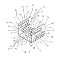
FIG. 1 is a perspective view of a grounding electrical connector in accordance with a first exemplary embodiment of the present invention; -
FIG. 2 is a side elevational view of the electrical connector ofFIG. 1 ; -
FIG. 3 is a rear elevational view of the electrical connector assembly ofFIG. 1 ; -
FIG. 4 is a front elevational view of the electrical connector ofFIG. 1 ; -
FIG. 5 is a top plan view of the electrical connector ofFIG. 1 ; -
FIG. 6 is a bottom plan view of the electrical connector ofFIG. 1 ; -
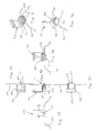
FIG. 7 is an upper perspective view of the electrical connector ofFIG. 1 connected to a support and receiving a conductor; -
FIG. 8 is a lower perspective view of the electrical connector connected to the support ofFIG. 7 ; -
FIG. 9 is a side elevational view of the electrical connector connected to the support ofFIG. 7 ; -
FIG. 10 is a front elevational view of the electrical connector connected to the support ofFIG. 7 ; -
FIG. 11 is a rear elevational view of the electrical connector connected to the support ofFIG. 7 ; -
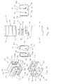
FIG. 12 is a perspective view of a grounding electrical connector in accordance with a second exemplary embodiment of the present invention; -
FIG. 13 is a top plan view of the electrical connector ofFIG. 12 ; -
FIG. 14 is a rear elevational view of the electrical connector ofFIG. 12 ; -
FIG. 15 is a side elevational view of the electrical connector ofFIG. 12 ; -
FIG. 16 is a front elevational view of the electrical connector ofFIG. 12 ; -
FIG. 17 is a bottom plan view of the electrical connector ofFIG. 12 ; -
FIG. 18 is a front perspective view of the electrical connector ofFIG. 12 connected to a support and receiving a conductor; -
FIG. 19 is a rear perspective view of the electrical connector connected to the support ofFIG. 18 ; -
FIG. 20 is a top plan view of the electrical connector connected to the support ofFIG. 18 ; -
FIG. 21 is a rear elevational view of the electrical connector connected to the support ofFIG. 18 ; -
FIG. 22 is a side elevational view of the electrical connector connected to the support ofFIG. 18 ; -
FIG. 23 is a front elevational view of the electrical connector connected to the support ofFIG. 18 ; -
FIG. 24 is a bottom plan view of the electrical connector connected to the support ofFIG. 18 ; -
FIG. 25 is a perspective view of a grounding electrical connector in accordance with a third exemplary embodiment of the present invention; -
FIG. 26 is a top plan view of the electrical connector ofFIG. 25 ; -
FIG. 27 is a rear elevational view of the electrical connector ofFIG. 25 ; -
FIG. 28 is a side elevational view of the electrical connector ofFIG. 25 ; -
FIG. 29 is a front elevational view of the electrical connector ofFIG. 25 ; -
FIG. 30 is a bottom plan view of the electrical connector ofFIG. 25 ; -
FIG. 31 is a front perspective view of the electrical connector ofFIG. 25 connected to a support and receiving a conductor; -
FIG. 32 is a rear perspective view of the electrical connector connected to the support ofFIG. 31 ; -
FIG. 33 is a top plan view of the electrical connector connected to the support ofFIG. 31 ; -
FIG. 34 is a rear elevational view of the electrical connector connected to the support ofFIG. 31 ; -
FIG. 35 is a side elevational view of the electrical connector connected to the support ofFIG. 31 ; -
FIG. 36 is a front elevational view of the electrical connector connected to the support ofFIG. 31 ; -
FIG. 37 is a bottom plan view of the electrical connector connected to the support ofFIG. 31 ; -
FIG. 38 is an upper perspective view of a grounding electrical connector in accordance with a fourth exemplary embodiment of the present invention; -
FIG. 39 is a lower perspective view of the electrical connector ofFIG. 38 ; -
FIG. 40 is a top plan view of the electrical connector ofFIG. 38 ; -
FIG. 41 is a rear elevational view of the electrical connector ofFIG. 38 ; -
FIG. 42 is a side elevational view of the electrical connector ofFIG. 38 ; -
FIG. 43 is a front elevational view of the electrical connector ofFIG. 38 ; -
FIG. 44 is a bottom plan view of the electrical connector ofFIG. 38 ; -
FIG. 45 is a front perspective view of the electrical connector ofFIG. 38 connected to a support and receiving a conductor; -
FIG. 46 is a rear perspective view of the electrical connector connected to the support ofFIG. 45 ; -
FIG. 47 is a top plan view of the electrical connector connected to the support ofFIG. 45 ; -
FIG. 48 is a rear elevational view of the electrical connector connected to the support ofFIG. 45 ; -
FIG. 49 is a side elevational view of the electrical connector connected to the support ofFIG. 45 ; -
FIG. 50 is a front elevational view of the electrical connector connected to the support ofFIG. 45 ; -
FIG. 51 is a bottom plan view of the electrical connector connected to the support ofFIG. 45 ; -
FIG. 52 is an upper perspective view of a grounding electrical connector in accordance with a fifth exemplary embodiment of the present invention; -
FIG. 53 is a lower perspective view of the grounding electrical connector ofFIG. 52 ; -
FIG. 54 is a top plan view of the electrical connector ofFIG. 52 ; -
FIG. 55 is a rear elevational view of the electrical connector ofFIG. 52 ; -
FIG. 56 is a side elevational view of the electrical connector ofFIG. 52 ; -
FIG. 57 is a front elevational view of the electrical connector ofFIG. 52 ; -
FIG. 58 is a bottom plan view of the electrical connector ofFIG. 52 ; -
FIG. 59 is a front perspective view of the electrical connector ofFIG. 52 connected to a support and receiving a conductor; -
FIG. 60 is a rear perspective view of the electrical connector connected to the support ofFIG. 59 ; -
FIG. 61 is a top plan view of the electrical connector connected to the support ofFIG. 59 ; -
FIG. 62 is a rear elevational view of the electrical connector connected to the support ofFIG. 59 ; -
FIG. 63 is a side elevational view of the electrical connector connected to the support ofFIG. 59 ; -
FIG. 64 is a front elevational view of the electrical connector connected to the support ofFIG. 59 ; and -
FIG. 65 is a bottom plan view of the electrical connector connected to the support ofFIG. 59 . - Throughout the drawings, like reference numerals will be understood to refer to like parts, components and structures.
- A grounding electrical connector in accordance with exemplary embodiments of the present invention is shown in
FIGS. 1 - 65 . The electrical connector is preferably unitarily formed as a single member and is made of a conductive material. The electrical connector is adapted to receive various conductor sizes and to be connected to supports having varying thicknesses. - A grounding
electrical connector 11 in accordance with a first exemplary embodiment of the present invention connects aground conductor 12 to asupport 13, as shown inFIGS. 7 - 11 . For example, the electrical connector can be used to connect an equipment ground conductor to a solar photovoltaic (PV) module frame or module mounting structure. - The
electrical connector 11 includes abase member 14, as shown inFIGS. 1 - 6 , and has anupper surface 15 and alower surface 16. Aresilient channel member 17 is connected to theupper surface 15 of the base member and has a plurality ofchannels 18 extending between first and secondopposite sides 21 and 22 of thebase member 14. As shown inFIGS. 1 and5 , thechannel member 17 has threechannels channel member 17 preferably does not extend the entire length of theupper surface 15 between the first andsecond sides 21 and 22, as shown inFIG. 1 . As shown inFIGS. 1 ,3 and 4 , theelectrical connector 11 is preferably substantially U-shaped. - A
first leg 23 extends outwardly from the first side 21 of thebase member 14. Preferably thefirst leg 23 is substantially perpendicular to thebase member 14, as shown inFIGS. 3 and 4 . Thefirst leg 23 has first and secondopposite sides first recess 26 extends inwardly from thefirst side 24 of thefirst leg 23. Asecond recess 27 extends inwardly from thesecond side 25 of thefirst leg 23. Thesecond recess 27 is preferably disposed between thefirst recess 26 and thebase member 14. - Upper and lower
flexible tabs opposite sides first recess 26, as shown inFIGS. 1 and2 . The distance between the free ends of theflexible tabs support 13 therein. - Upper and lower
flexible tabs opposite sides second recess 27, as shown inFIGS. 1 and2 . The distance between the free ends of theflexible tabs support 13 therein. - A plurality of pairs of grooves are formed in the free ends of the
flexible tabs FIGS. 1 and2 , to facilitate receiving theconductor 12 therebetween. A first pair ofgrooves second recess 27. A second pair ofgrooves grooves grooves second recess 27. The groove sizes are different to facilitate receiving different conductor sizes. As shown inFIG. 2 , the grooves increase in size from the first pair to the third pair. For example, the first pair ofgrooves grooves grooves electrical connector 11. - A
second leg 38 is substantially similar to thefirst leg 23 and extends outwardly from thesecond side 22 of thebase member 14. Preferably thesecond leg 38 is substantially perpendicular to thebase member 14, as shown inFIGS. 3 and 4 . Thesecond leg 38 has first and secondopposite sides first recess 41 extends inwardly from thefirst side 39 of thesecond leg 38, and is aligned with thefirst recess 26 in thefirst leg 23. Asecond recess 42 extends inwardly from thesecond side 40 of thesecond leg 38, and is aligned with thesecond recess 27 in thefirst leg 23. Thesecond recess 42 is preferably disposed between thefirst recess 41 of thesecond leg 38 and thebase member 14. - Upper and lower
flexible tabs opposite sides first recess 41, as shown inFIG. 1 . The distance between the free ends of theflexible tabs support 13 therein. - Upper and lower
flexible tabs opposite sides second recess 42, as shown inFIG. 1 . The distance between the free ends of theflexible tabs support 13 therein. - A plurality of pairs of grooves are formed in the free ends of the
flexible tabs FIGS. 1 and11 , to facilitate receiving theconductor 12 therebetween. A first pair ofgrooves second recess 42. A second pair ofgrooves grooves grooves second recess 42. The groove sizes are different to facilitate receiving different conductor sizes. As shown inFIG. 11 , the grooves increase in size from the first pair to the third pair. For example, the first pair ofgrooves grooves grooves electrical connector 11. - The
channel member 17 is connected to anupper surface 15 of thebase member 14, as shown inFIGS. 1 and3 - 5 . Preferably, arear wall 66 connects thechannel member 17 to thebase member 14, thereby providing flexibility to thechannel member 17 such that thechannel member 17 extends from afixed end 67 connected to the rear wall to afree end 68 spaced from therear wall 66. Thechannels first side 62 to asecond side 63 of thechannel member 17, as shown inFIG. 1 . Preferably, thefirst side 62 is spaced inwardly from thefirst leg 23 and thesecond side 63 is spaced inwardly from thesecond leg 38, as shown inFIGS. 3 and 4 . Alower surface 64 of thechannel member 17 is spaced upwardly from thebase member 14, as shown inFIGS. 7 and 8 . Arecess 65 is formed in thebase member 14 corresponding to thechannel member 17. The freefront end 66 of thechannel member 17 is resilient such that various diameter conductors can be quickly and easily inserted in thesecond recesses second legs - The grounding
electrical connector 11 is preferably unitarily formed as a single member and is made of a conductive material, such as stainless steel. The groundingelectrical connector 11 can be stamped out of a single piece of conductive material. - As shown in
FIGS. 7 - 11 , anelectrical connector 11 in accordance with an exemplary embodiment of the present invention is connected to thesupport 13, such as a solar PV module frame or module mounting structure. Theelectrical connector 11 receives theconductor 12, such as an equipment ground conductor, to mechanically and electrically connect theconductor 12 to thesupport 13. - The first recesses 26 and 41 in the first and
second legs planar member 69 of thesupport 13. The decreased distance between the first ends of theflexible tabs first leg 23 and theflexible tabs second leg 38 facilitate inserting theplanar member 69 in thefirst recesses electrical connector 11 causes the flexible tabs to tighten their grip on theplanar member 69. The flexibility of the tabs facilitates connecting theelectrical connector 11 to supports having various thicknesses. - The second recesses 27 and 42 in the first and
second legs conductor 12. The decreased distance between the first ends of theflexible tabs first leg 23 and theflexible tabs second leg 38 facilitate inserting theconductor 12 in thesecond recesses conductor 12 causes the flexible tabs to tighten their grip on theconductor 13. - The oppositely disposed pairs of grooves in the flexible tabs of the
second recesses FIGS. 10 and 11 , three pairs of grooves are shown sized to receive 6, 8 and 10 AWG conductors. Thechannels channel member 17 have sizes corresponding to the pair of grooves between which the channels extend, thereby facilitating receiving theconductor 12. Thefree end 68 of thechannel member 17 facilitates flexing of thechannel member 17 to more easily receive the insertedconductor 12 and to increase conductive surface area contact between theconductor 12 and theconnector 11. - A grounding
electrical connector 111 in accordance with a second exemplary embodiment of the present invention is shown inFIGS. 12 - 17 . Theelectrical connector 111 is shown connected to asupport 113 and receiving aground conductor 112 inFIGS. 18 - 24 . Theelectrical connector 111 is substantially similar to theelectrical connector 11 of the first exemplary embodiment shown inFIGS. 1 - 11 . Similar features are indicated with the same reference numeral, except in the 100 series, e.g., 1xx. - The
electrical connector 111 includes third andfourth legs second legs FIGS. 12 - 17 . The third andfourth legs base member 114 from which the first andsecond legs fourth legs second legs - A recess or
gap 173 is formed betweenfree ends fourth legs FIGS. 12 and 13 . Thegap 173 tapers or narrows from afirst end 176 to asecond end 177 of the gap. Thegap 173 receives the substantiallyplanar member 169 of thesupport 113, as shown inFIGS. 18 - 24 . Inserting theplanar member 169 of thesupport 113 in thegap 173 between the third andfourth legs electrical connector 111 causes theconductor 112 to be more tightly gripped. - A grounding
electrical connector 211 in accordance with a third exemplary embodiment of the present invention is shown inFIGS. 25 - 30 . Theelectrical connector 211 is shown connected to asupport 213 and receiving aground conductor 212 inFIGS. 31 - 37 . Theelectrical connector 211 is substantially similar to theelectrical connector 11 of the first exemplary embodiment shown inFIGS. 1-11 . Similar features are indicated with the same reference numeral, except in the 200 series, e.g., 2xx. - The
electrical connector 211 includes third andfourth legs second legs FIGS. 25, 27 and 29 . The third andfourth legs base member 214 from which the first andsecond legs fourth legs second legs - Fifth and
sixth legs base member 214 from the third andfourth legs FIGS. 25, 27 and 29 . The fifth andsixth legs second legs -
Upper openings sixth legs openings second legs planar member 269 of thesupport 213, as shown inFIGS. 31 - 37 . Theupper openings sixth legs -
Lower openings sixth legs openings second legs conductor 212, as shown inFIGS. 31 - 37 . Thelower openings sixth legs lower openings openings lower openings - As shown in
FIG. 30 , thebase member 214 is preferably a substantially planar and continuous member. Thelower openings sixth legs conductor 212 such that a channel member 17 (FIG. 1 ) is not required. The free ends of the fifth andsixth legs base member 214, as shown inFIGS. 27 and 29 . The fifth andsixth legs planar support member 269 and theconductor 212, thereby improving the retention and electrical connection of the groundingelectrical connector 211. - A grounding
electrical connector 311 in accordance with a fourth exemplary embodiment of the present invention is shown inFIGS. 38 - 44 . Theelectrical connector 311 is shown connected to asupport 313 and receiving aground conductor 312 inFIGS. 45 - 51 . Theelectrical connector 311 is substantially similar to theelectrical connector 211 of the third exemplary embodiment shown inFIGS. 25 - 37 . Similar features are indicated with the same reference numeral, except in the 300 series, e.g., 3xx. -
Tabs sixth legs second legs FIGS. 38, 39, 41 and 43 . A plurality ofgrooves 381 are formed in the free ends of the fifth andsixth legs openings second legs tabs conductor 312 and creating an electrical connection thereto. - A grounding
electrical connector 411 in accordance with a fifth exemplary embodiment of the present invention is shown inFIGS. 52 - 58 . Theelectrical connector 411 is shown connected to asupport 413 and receiving aground conductor 412 inFIGS. 59 - 65 . Theelectrical connector 411 is substantially similar to theelectrical connector 11 of the first exemplary embodiment shown inFIGS. 1 - 11 . Similar features are indicated with the same reference numeral, except in the 400 series, e.g., 4xx. - The
electrical connector 411 is preferably made from a rectangular tube. Theelectrical connector 411 has an upperplanar member 491 substantially parallel to thebase member 414, as shown inFIGS. 52, 55 and 57 . The upperplanar member 491 extends between the first andsecond legs electrical connector 411 from a tube provides rigidity to the resulting electrical connector, in addition to providing manufacturing options. - The foregoing embodiments and advantages are merely exemplary and are not to be construed as limiting the scope of the present invention. The description of exemplary embodiments of the present invention is intended to be illustrative, and not to limit the scope of the present invention. Various modifications, alternatives and variations will be apparent to those of ordinary skill in the art, and are intended to fall within the scope of the invention as defined in the appended claims and their equivalents.
Claims (20)
- An electrical connector, comprising:a base member;first and second legs extending outwardly from said base member;a first recess defined by said first and second legs for receiving a support;second recesses extending inwardly from second sides of said first and second legs; anda plurality of oppositely disposed grooves formed in said second recesses, at least two pairs of said oppositely disposed grooves having different sizes for receiving various conductor sizes.
- The electrical connector according to claim 1, wherein
said first recess includes first recesses extending inwardly from first sides of said first and second legs. - The electrical connector according to claim 1, wherein
said first and second legs extend substantially perpendicularly from said base member. - The electrical connector according to claim 1, wherein
said first sides of said first and second legs are opposite said second sides of said first and second legs. - The electrical connector according to claim 1, wherein
said electrical connector is unitarily formed as a single piece. - The electrical connector according to claim 1, wherein
a channel member is connected to said base member and a channel extends between each pair of said oppositely disposed grooves to facilitate receiving the conductor. - The electrical connector according to claim 6, wherein
said channel member has a fixed end connected to said base member and a free end. - The electrical connector according to claim 1, wherein
each of said second recesses has upper and lower flexible tabs extending outwardly from said respective leg and toward one another. - The electrical connector according to claim 8, wherein
said plurality of grooves are formed in free ends of said upper and lower flexible tabs of said second recesses. - The electrical connector according to claim 1, wherein
each of said first recesses has upper and lower flexible tabs extending outwardly from said respective leg and toward one another. - The electrical connector according to claim 10, wherein
a distance between free ends of said upper and lower flexible tabs of said first recesses of said first and second legs decreases toward a closed end of said second recesses. - The electrical connector according to claim 8, wherein
a distance between free ends of said upper and lower flexible tabs of said second recesses of said first and second legs decreases toward a closed end of said first recesses. - The electrical connector according to claim 6, wherein
each of said channels has a size corresponding to said oppositely disposed grooves between which said channel extends. - The electrical connector according to claim 10, wherein
said second recesses are disposed between said first recesses and said base member. - The electrical connector according to claim 1, wherein
sides of said channel member are spaced inwardly from said first and second legs. - An electrical connector, comprising:a base member;first and second legs extending outwardly from said base member;first recesses extending inwardly from first sides of said first and second legs, said first recesses being connectable to a support;first pairs of upper and lower flexible tabs extending outwardly from upper and lower sides of said first recesses in said first and second legs and toward one another;second recesses extending inwardly from second sides of said first and second legs;second pairs of upper and lower flexible tabs extending outwardly from upper and lower sides of said second recesses in said first and second legs and toward one another;a plurality of oppositely disposed grooves formed in free ends of said second pairs of upper and lower flexible tabs, at least two pairs of said oppositely disposed grooves having different sizes for receiving various conductor sizes; anda channel member connected to said base member and having a channel extending between each pair of oppositely disposed grooves to facilitate receiving a conductor.
- The electrical connector according to claim 16, wherein
said electrical connector is unitarily formed as a single piece. - The electrical connector according to claim 16, wherein
said channel member has a fixed end connected to said base member and a free end. - The electrical connector according to claim 16, wherein
said second recesses are disposed between said first recesses and said base member. - The electrical connector according to claim 16, wherein
each of said channels has a size corresponding to said oppositely disposed grooves between which said channel extends.
Applications Claiming Priority (1)
| Application Number | Priority Date | Filing Date | Title |
|---|---|---|---|
| US13/959,048 US8974245B2 (en) | 2013-08-05 | 2013-08-05 | Grounding electrical connector |
Publications (2)
| Publication Number | Publication Date |
|---|---|
| EP2835869A1 true EP2835869A1 (en) | 2015-02-11 |
| EP2835869B1 EP2835869B1 (en) | 2019-06-26 |
Family
ID=51265634
Family Applications (1)
| Application Number | Title | Priority Date | Filing Date |
|---|---|---|---|
| EP14275164.3A Active EP2835869B1 (en) | 2013-08-05 | 2014-08-05 | Grounding electrical connector |
Country Status (7)
| Country | Link |
|---|---|
| US (1) | US8974245B2 (en) |
| EP (1) | EP2835869B1 (en) |
| CN (2) | CN104348039B (en) |
| AU (1) | AU2014208190B2 (en) |
| BR (1) | BR102014019249B1 (en) |
| CA (1) | CA2858017C (en) |
| MX (1) | MX338868B (en) |
Cited By (1)
| Publication number | Priority date | Publication date | Assignee | Title |
|---|---|---|---|---|
| WO2020182738A1 (en) * | 2019-03-13 | 2020-09-17 | OBO Bettermann Produktion Deutschland GmbH & Co. KG | Earth wire holder, cable tray having an earth wire holder of this kind, and earth wire kit |
Families Citing this family (9)
| Publication number | Priority date | Publication date | Assignee | Title |
|---|---|---|---|---|
| US9450130B2 (en) | 2011-01-27 | 2016-09-20 | Sunpower Corporation | Frame-mounted wire management device |
| US11817818B2 (en) * | 2015-07-24 | 2023-11-14 | Tecsi Solar, Inc. | Module frame with cable management flange |
| WO2017019433A1 (en) * | 2015-07-24 | 2017-02-02 | Sunedison, Inc. | Ergonomic solar module frame with cable management flange |
| US9923511B2 (en) * | 2015-08-03 | 2018-03-20 | Jason Sen Xie | Connecting solar modules |
| WO2018031650A1 (en) * | 2016-08-09 | 2018-02-15 | Hubbell Incorporated | Wire management clips |
| AU2018328094B2 (en) | 2017-09-06 | 2024-02-15 | Hubbell Incorporated | Cable clips |
| US10847960B1 (en) | 2019-05-16 | 2020-11-24 | Hubbell Incorporated | Multi-directional cable clip |
| EP4293845A1 (en) | 2022-06-15 | 2023-12-20 | Unex Aparellaje Electrico S.L. | Attaching piece for attaching a cable to a support, and corresponding assembly |
| US12098803B2 (en) * | 2023-02-22 | 2024-09-24 | Panelclaw, Inc. | Frame enhancer |
Citations (5)
| Publication number | Priority date | Publication date | Assignee | Title |
|---|---|---|---|---|
| US4384753A (en) * | 1981-06-26 | 1983-05-24 | Amp Incorporated | Electrical edge connector |
| US7195513B1 (en) * | 2006-06-28 | 2007-03-27 | Tyco Electronics Corporation | Self-locking wire termination clip |
| US20090111311A1 (en) * | 2007-10-29 | 2009-04-30 | Tyco Electronics Corporation | One-piece pc board magnet wire terminal |
| US20110151703A1 (en) * | 2009-12-23 | 2011-06-23 | Hubbell Incorporated | Solar panel grounding connector |
| EP2528166A1 (en) * | 2011-05-24 | 2012-11-28 | A. Raymond Et Cie | Earthing clip and earthing assembly |
Family Cites Families (29)
| Publication number | Priority date | Publication date | Assignee | Title |
|---|---|---|---|---|
| US3405385A (en) * | 1966-02-02 | 1968-10-08 | Western Electric Co | Quick connect solderless wire connector |
| US4029384A (en) * | 1975-01-20 | 1977-06-14 | Illinois Tool Works Inc. | Grounding clip |
| US4527857A (en) * | 1983-04-18 | 1985-07-09 | Amp Incorporated | Terminal for connecting a wire to a blade type terminal |
| GB2203600A (en) | 1987-04-13 | 1988-10-19 | Johnson Electric Ind Mfg | A device for connecting a wire to a terminal |
| FR2642905B1 (en) | 1989-02-09 | 1991-04-12 | Mars Actel | CONNECTION DEVICE FOR TWO INSULATED ELECTRICAL CONDUCTORS AT DIFFERENT LEVELS |
| US5358423A (en) * | 1993-11-24 | 1994-10-25 | Minnesota Mining And Manufacturing Company | Connecting clip |
| US5451167A (en) * | 1994-07-28 | 1995-09-19 | Illinois Tool Works Inc. | Grounding clip |
| DE59701532D1 (en) * | 1996-09-27 | 2000-05-31 | Tyco Electronics Logistics Ag | CONTACT ORGAN WITH DOUBLE CUTTING TERMINAL |
| JPH1167413A (en) * | 1997-08-20 | 1999-03-09 | Sumitomo Wiring Syst Ltd | Bulb socket, bulb socket-to-wire connection method, and bulb socket-to-wire connection jig |
| US6106310A (en) * | 1997-11-19 | 2000-08-22 | The Whitaker Corporation | Panel-grounding contact |
| DE29721354U1 (en) * | 1997-12-03 | 1998-02-12 | Weidmüller Interface GmbH & Co, 32760 Detmold | Connectors for electrical conductors |
| DE19906725C1 (en) | 1999-02-18 | 2001-01-11 | Harting Kgaa | Conductor connection element |
| JP4187338B2 (en) * | 1999-03-01 | 2008-11-26 | モレックス インコーポレーテッド | Electrical connector |
| US6325659B1 (en) | 2000-09-29 | 2001-12-04 | Illinois Tool Works Inc. | Electrical connector for solderless connection to edge card connector, and dual connector-printed circuit board assembly |
| US6312288B1 (en) * | 2000-10-25 | 2001-11-06 | Illinois Tool Works Inc. | Low profile combination switch and connector assembly |
| JP3875864B2 (en) * | 2001-09-18 | 2007-01-31 | 矢崎総業株式会社 | Terminal fitting |
| DE10349486A1 (en) | 2002-10-25 | 2004-05-13 | Yazaki Corporation | Connection terminal for plug connection has tubular connector connecting part, wire pressure contact part with pressure contact blade, wire contact direction parallel to connector connection direction |
| JP2005294217A (en) * | 2004-04-05 | 2005-10-20 | Jst Mfg Co Ltd | Pressure contact type contact and electrical connector using the same |
| JP4477423B2 (en) | 2004-06-08 | 2010-06-09 | Smk株式会社 | Connector structure |
| US20070254521A1 (en) | 2006-04-28 | 2007-11-01 | D Agostini Roberto | Insulation displacement terminal |
| US7396264B2 (en) * | 2006-05-02 | 2008-07-08 | K.S. Terminals, Inc. | Electrical-tap connector |
| BRPI0602294A (en) | 2006-06-14 | 2008-01-29 | Tyco Electronics Brasil Ltda | idc terminal with closed configuration |
| DE102007002769B4 (en) | 2007-01-18 | 2008-10-16 | Adc Gmbh | Terminal strip |
| US7326069B1 (en) | 2007-03-19 | 2008-02-05 | Tyco Electronics Corporation | Grounding clip system with a sliding shuttle |
| USD606025S1 (en) | 2009-05-27 | 2009-12-15 | Cyber Power System Inc. | Cable guide bracket |
| DE102009047043A1 (en) | 2009-10-19 | 2011-04-21 | Robert Bosch Gmbh | Solderless electrical connection |
| TWM406833U (en) | 2010-12-14 | 2011-07-01 | Ant Percision Industry Co Ltd | Terminal structure and electrical connector using the same |
| US9450130B2 (en) | 2011-01-27 | 2016-09-20 | Sunpower Corporation | Frame-mounted wire management device |
| US8708733B2 (en) | 2011-09-14 | 2014-04-29 | Interplex Industries, Inc. | Large deflection constrained insulation displacement terminal and connector |
-
2013
- 2013-08-05 US US13/959,048 patent/US8974245B2/en not_active Expired - Fee Related
-
2014
- 2014-07-29 AU AU2014208190A patent/AU2014208190B2/en active Active
- 2014-07-31 CA CA2858017A patent/CA2858017C/en active Active
- 2014-08-01 MX MX2014009318A patent/MX338868B/en active IP Right Grant
- 2014-08-04 BR BR102014019249-2A patent/BR102014019249B1/en active IP Right Grant
- 2014-08-05 CN CN201410390376.8A patent/CN104348039B/en not_active Expired - Fee Related
- 2014-08-05 CN CN201810447483.8A patent/CN108615997B/en active Active
- 2014-08-05 EP EP14275164.3A patent/EP2835869B1/en active Active
Patent Citations (5)
| Publication number | Priority date | Publication date | Assignee | Title |
|---|---|---|---|---|
| US4384753A (en) * | 1981-06-26 | 1983-05-24 | Amp Incorporated | Electrical edge connector |
| US7195513B1 (en) * | 2006-06-28 | 2007-03-27 | Tyco Electronics Corporation | Self-locking wire termination clip |
| US20090111311A1 (en) * | 2007-10-29 | 2009-04-30 | Tyco Electronics Corporation | One-piece pc board magnet wire terminal |
| US20110151703A1 (en) * | 2009-12-23 | 2011-06-23 | Hubbell Incorporated | Solar panel grounding connector |
| EP2528166A1 (en) * | 2011-05-24 | 2012-11-28 | A. Raymond Et Cie | Earthing clip and earthing assembly |
Cited By (3)
| Publication number | Priority date | Publication date | Assignee | Title |
|---|---|---|---|---|
| WO2020182738A1 (en) * | 2019-03-13 | 2020-09-17 | OBO Bettermann Produktion Deutschland GmbH & Co. KG | Earth wire holder, cable tray having an earth wire holder of this kind, and earth wire kit |
| US11664611B2 (en) | 2019-03-13 | 2023-05-30 | Obo Bettermann Produktion Deutschland Gmbh & Co Kg | Holder for a protective conductor and cable tray with such holder for a protective conductor and protective conductor set |
| EP3906599B1 (en) * | 2019-03-13 | 2024-09-11 | OBO Bettermann Produktion Deutschland GmbH & Co.KG | Cable tray having an earth wire holder |
Also Published As
| Publication number | Publication date |
|---|---|
| CA2858017A1 (en) | 2015-02-05 |
| EP2835869B1 (en) | 2019-06-26 |
| MX338868B (en) | 2016-05-03 |
| US8974245B2 (en) | 2015-03-10 |
| AU2014208190A1 (en) | 2015-02-19 |
| CN108615997B (en) | 2020-12-11 |
| CN108615997A (en) | 2018-10-02 |
| CN104348039A (en) | 2015-02-11 |
| CA2858017C (en) | 2020-07-21 |
| AU2014208190B2 (en) | 2018-07-12 |
| MX2014009318A (en) | 2015-03-04 |
| CN104348039B (en) | 2018-11-16 |
| BR102014019249B1 (en) | 2021-10-05 |
| US20150034362A1 (en) | 2015-02-05 |
| BR102014019249A2 (en) | 2015-12-01 |
Similar Documents
| Publication | Publication Date | Title |
|---|---|---|
| US8974245B2 (en) | Grounding electrical connector | |
| CN210120249U (en) | Metal clip for electrically connecting a conductor to a metal element | |
| US7318732B2 (en) | Wide safety strap for electrical fixtures | |
| US9595772B2 (en) | Adjustable bonding washer | |
| US9257804B1 (en) | Pitch agnostic bus-bar with pitch agnostic blind mate connector | |
| US20130314889A1 (en) | Power input terminal block housing and cover | |
| AU2015204300B2 (en) | Terminal block with ground strap, spring force terminals, and screw lug terminal | |
| AU2020203061A1 (en) | Multi-directional cable clip for short flanges | |
| US20110244719A1 (en) | Junction box with improved heat dissipation | |
| CN101554720B (en) | Progressive crimping method | |
| US9825378B2 (en) | Mounting clip | |
| KR20160140724A (en) | Fastening system for assembling appliances, in particular electrical appliances | |
| WO2014178041A2 (en) | Electrical connecting device | |
| CN201946927U (en) | Solar Junction Box | |
| US9017093B1 (en) | Electric meter socket assembly | |
| US20170093075A1 (en) | Connector | |
| CN204045762U (en) | Copper bar conductor jointer | |
| CN203645004U (en) | Insertion reed | |
| US10714873B2 (en) | Plug with protective conductor bridge | |
| CN205178097U (en) | Wiring terminal | |
| CN203800396U (en) | Abnormity busbar connection assembly | |
| US9397409B2 (en) | Electrical connector | |
| CN207517906U (en) | A stamped metal ground block | |
| CN104241886B (en) | Copper bar conductor jointer | |
| WO2015109280A1 (en) | Terminal strip |
Legal Events
| Date | Code | Title | Description |
|---|---|---|---|
| PUAI | Public reference made under article 153(3) epc to a published international application that has entered the european phase |
Free format text: ORIGINAL CODE: 0009012 |
|
| 17P | Request for examination filed |
Effective date: 20140805 |
|
| AK | Designated contracting states |
Kind code of ref document: A1 Designated state(s): AL AT BE BG CH CY CZ DE DK EE ES FI FR GB GR HR HU IE IS IT LI LT LU LV MC MK MT NL NO PL PT RO RS SE SI SK SM TR |
|
| AX | Request for extension of the european patent |
Extension state: BA ME |
|
| R17P | Request for examination filed (corrected) |
Effective date: 20150811 |
|
| RBV | Designated contracting states (corrected) |
Designated state(s): AL AT BE BG CH CY CZ DE DK EE ES FI FR GB GR HR HU IE IS IT LI LT LU LV MC MK MT NL NO PL PT RO RS SE SI SK SM TR |
|
| STAA | Information on the status of an ep patent application or granted ep patent |
Free format text: STATUS: EXAMINATION IS IN PROGRESS |
|
| 17Q | First examination report despatched |
Effective date: 20170519 |
|
| RIC1 | Information provided on ipc code assigned before grant |
Ipc: H01R 4/24 20180101ALN20181123BHEP Ipc: H01R 4/22 20060101AFI20181123BHEP Ipc: H01R 4/64 20060101ALI20181123BHEP |
|
| GRAP | Despatch of communication of intention to grant a patent |
Free format text: ORIGINAL CODE: EPIDOSNIGR1 |
|
| STAA | Information on the status of an ep patent application or granted ep patent |
Free format text: STATUS: GRANT OF PATENT IS INTENDED |
|
| INTG | Intention to grant announced |
Effective date: 20190108 |
|
| GRAS | Grant fee paid |
Free format text: ORIGINAL CODE: EPIDOSNIGR3 |
|
| GRAA | (expected) grant |
Free format text: ORIGINAL CODE: 0009210 |
|
| STAA | Information on the status of an ep patent application or granted ep patent |
Free format text: STATUS: THE PATENT HAS BEEN GRANTED |
|
| AK | Designated contracting states |
Kind code of ref document: B1 Designated state(s): AL AT BE BG CH CY CZ DE DK EE ES FI FR GB GR HR HU IE IS IT LI LT LU LV MC MK MT NL NO PL PT RO RS SE SI SK SM TR |
|
| REG | Reference to a national code |
Ref country code: GB Ref legal event code: FG4D |
|
| REG | Reference to a national code |
Ref country code: CH Ref legal event code: EP |
|
| REG | Reference to a national code |
Ref country code: AT Ref legal event code: REF Ref document number: 1149373 Country of ref document: AT Kind code of ref document: T Effective date: 20190715 |
|
| REG | Reference to a national code |
Ref country code: DE Ref legal event code: R096 Ref document number: 602014049011 Country of ref document: DE |
|
| REG | Reference to a national code |
Ref country code: IE Ref legal event code: FG4D |
|
| REG | Reference to a national code |
Ref country code: NL Ref legal event code: MP Effective date: 20190626 |
|
| PG25 | Lapsed in a contracting state [announced via postgrant information from national office to epo] |
Ref country code: AL Free format text: LAPSE BECAUSE OF FAILURE TO SUBMIT A TRANSLATION OF THE DESCRIPTION OR TO PAY THE FEE WITHIN THE PRESCRIBED TIME-LIMIT Effective date: 20190626 Ref country code: SE Free format text: LAPSE BECAUSE OF FAILURE TO SUBMIT A TRANSLATION OF THE DESCRIPTION OR TO PAY THE FEE WITHIN THE PRESCRIBED TIME-LIMIT Effective date: 20190626 Ref country code: FI Free format text: LAPSE BECAUSE OF FAILURE TO SUBMIT A TRANSLATION OF THE DESCRIPTION OR TO PAY THE FEE WITHIN THE PRESCRIBED TIME-LIMIT Effective date: 20190626 Ref country code: HR Free format text: LAPSE BECAUSE OF FAILURE TO SUBMIT A TRANSLATION OF THE DESCRIPTION OR TO PAY THE FEE WITHIN THE PRESCRIBED TIME-LIMIT Effective date: 20190626 Ref country code: NO Free format text: LAPSE BECAUSE OF FAILURE TO SUBMIT A TRANSLATION OF THE DESCRIPTION OR TO PAY THE FEE WITHIN THE PRESCRIBED TIME-LIMIT Effective date: 20190926 Ref country code: LT Free format text: LAPSE BECAUSE OF FAILURE TO SUBMIT A TRANSLATION OF THE DESCRIPTION OR TO PAY THE FEE WITHIN THE PRESCRIBED TIME-LIMIT Effective date: 20190626 |
|
| PGFP | Annual fee paid to national office [announced via postgrant information from national office to epo] |
Ref country code: FR Payment date: 20190919 Year of fee payment: 6 |
|
| REG | Reference to a national code |
Ref country code: LT Ref legal event code: MG4D |
|
| PG25 | Lapsed in a contracting state [announced via postgrant information from national office to epo] |
Ref country code: RS Free format text: LAPSE BECAUSE OF FAILURE TO SUBMIT A TRANSLATION OF THE DESCRIPTION OR TO PAY THE FEE WITHIN THE PRESCRIBED TIME-LIMIT Effective date: 20190626 Ref country code: BG Free format text: LAPSE BECAUSE OF FAILURE TO SUBMIT A TRANSLATION OF THE DESCRIPTION OR TO PAY THE FEE WITHIN THE PRESCRIBED TIME-LIMIT Effective date: 20190926 Ref country code: LV Free format text: LAPSE BECAUSE OF FAILURE TO SUBMIT A TRANSLATION OF THE DESCRIPTION OR TO PAY THE FEE WITHIN THE PRESCRIBED TIME-LIMIT Effective date: 20190626 Ref country code: GR Free format text: LAPSE BECAUSE OF FAILURE TO SUBMIT A TRANSLATION OF THE DESCRIPTION OR TO PAY THE FEE WITHIN THE PRESCRIBED TIME-LIMIT Effective date: 20190927 |
|
| PGFP | Annual fee paid to national office [announced via postgrant information from national office to epo] |
Ref country code: GB Payment date: 20190919 Year of fee payment: 6 |
|
| REG | Reference to a national code |
Ref country code: AT Ref legal event code: MK05 Ref document number: 1149373 Country of ref document: AT Kind code of ref document: T Effective date: 20190626 |
|
| PG25 | Lapsed in a contracting state [announced via postgrant information from national office to epo] |
Ref country code: NL Free format text: LAPSE BECAUSE OF FAILURE TO SUBMIT A TRANSLATION OF THE DESCRIPTION OR TO PAY THE FEE WITHIN THE PRESCRIBED TIME-LIMIT Effective date: 20190626 Ref country code: EE Free format text: LAPSE BECAUSE OF FAILURE TO SUBMIT A TRANSLATION OF THE DESCRIPTION OR TO PAY THE FEE WITHIN THE PRESCRIBED TIME-LIMIT Effective date: 20190626 Ref country code: AT Free format text: LAPSE BECAUSE OF FAILURE TO SUBMIT A TRANSLATION OF THE DESCRIPTION OR TO PAY THE FEE WITHIN THE PRESCRIBED TIME-LIMIT Effective date: 20190626 Ref country code: SK Free format text: LAPSE BECAUSE OF FAILURE TO SUBMIT A TRANSLATION OF THE DESCRIPTION OR TO PAY THE FEE WITHIN THE PRESCRIBED TIME-LIMIT Effective date: 20190626 Ref country code: RO Free format text: LAPSE BECAUSE OF FAILURE TO SUBMIT A TRANSLATION OF THE DESCRIPTION OR TO PAY THE FEE WITHIN THE PRESCRIBED TIME-LIMIT Effective date: 20190626 Ref country code: CZ Free format text: LAPSE BECAUSE OF FAILURE TO SUBMIT A TRANSLATION OF THE DESCRIPTION OR TO PAY THE FEE WITHIN THE PRESCRIBED TIME-LIMIT Effective date: 20190626 Ref country code: PT Free format text: LAPSE BECAUSE OF FAILURE TO SUBMIT A TRANSLATION OF THE DESCRIPTION OR TO PAY THE FEE WITHIN THE PRESCRIBED TIME-LIMIT Effective date: 20191028 |
|
| PG25 | Lapsed in a contracting state [announced via postgrant information from national office to epo] |
Ref country code: IS Free format text: LAPSE BECAUSE OF FAILURE TO SUBMIT A TRANSLATION OF THE DESCRIPTION OR TO PAY THE FEE WITHIN THE PRESCRIBED TIME-LIMIT Effective date: 20191026 Ref country code: IT Free format text: LAPSE BECAUSE OF FAILURE TO SUBMIT A TRANSLATION OF THE DESCRIPTION OR TO PAY THE FEE WITHIN THE PRESCRIBED TIME-LIMIT Effective date: 20190626 Ref country code: SM Free format text: LAPSE BECAUSE OF FAILURE TO SUBMIT A TRANSLATION OF THE DESCRIPTION OR TO PAY THE FEE WITHIN THE PRESCRIBED TIME-LIMIT Effective date: 20190626 Ref country code: ES Free format text: LAPSE BECAUSE OF FAILURE TO SUBMIT A TRANSLATION OF THE DESCRIPTION OR TO PAY THE FEE WITHIN THE PRESCRIBED TIME-LIMIT Effective date: 20190626 |
|
| PG25 | Lapsed in a contracting state [announced via postgrant information from national office to epo] |
Ref country code: TR Free format text: LAPSE BECAUSE OF FAILURE TO SUBMIT A TRANSLATION OF THE DESCRIPTION OR TO PAY THE FEE WITHIN THE PRESCRIBED TIME-LIMIT Effective date: 20190626 |
|
| PG25 | Lapsed in a contracting state [announced via postgrant information from national office to epo] |
Ref country code: PL Free format text: LAPSE BECAUSE OF FAILURE TO SUBMIT A TRANSLATION OF THE DESCRIPTION OR TO PAY THE FEE WITHIN THE PRESCRIBED TIME-LIMIT Effective date: 20190626 Ref country code: DK Free format text: LAPSE BECAUSE OF FAILURE TO SUBMIT A TRANSLATION OF THE DESCRIPTION OR TO PAY THE FEE WITHIN THE PRESCRIBED TIME-LIMIT Effective date: 20190626 |
|
| PG25 | Lapsed in a contracting state [announced via postgrant information from national office to epo] |
Ref country code: CH Free format text: LAPSE BECAUSE OF NON-PAYMENT OF DUE FEES Effective date: 20190831 Ref country code: MC Free format text: LAPSE BECAUSE OF FAILURE TO SUBMIT A TRANSLATION OF THE DESCRIPTION OR TO PAY THE FEE WITHIN THE PRESCRIBED TIME-LIMIT Effective date: 20190626 Ref country code: IS Free format text: LAPSE BECAUSE OF FAILURE TO SUBMIT A TRANSLATION OF THE DESCRIPTION OR TO PAY THE FEE WITHIN THE PRESCRIBED TIME-LIMIT Effective date: 20200224 Ref country code: LU Free format text: LAPSE BECAUSE OF NON-PAYMENT OF DUE FEES Effective date: 20190805 Ref country code: LI Free format text: LAPSE BECAUSE OF NON-PAYMENT OF DUE FEES Effective date: 20190831 |
|
| REG | Reference to a national code |
Ref country code: BE Ref legal event code: MM Effective date: 20190831 |
|
| REG | Reference to a national code |
Ref country code: DE Ref legal event code: R097 Ref document number: 602014049011 Country of ref document: DE |
|
| PLBE | No opposition filed within time limit |
Free format text: ORIGINAL CODE: 0009261 |
|
| STAA | Information on the status of an ep patent application or granted ep patent |
Free format text: STATUS: NO OPPOSITION FILED WITHIN TIME LIMIT |
|
| PG2D | Information on lapse in contracting state deleted |
Ref country code: IS |
|
| PG25 | Lapsed in a contracting state [announced via postgrant information from national office to epo] |
Ref country code: IE Free format text: LAPSE BECAUSE OF NON-PAYMENT OF DUE FEES Effective date: 20190805 |
|
| 26N | No opposition filed |
Effective date: 20200603 |
|
| PG25 | Lapsed in a contracting state [announced via postgrant information from national office to epo] |
Ref country code: BE Free format text: LAPSE BECAUSE OF NON-PAYMENT OF DUE FEES Effective date: 20190831 Ref country code: SI Free format text: LAPSE BECAUSE OF FAILURE TO SUBMIT A TRANSLATION OF THE DESCRIPTION OR TO PAY THE FEE WITHIN THE PRESCRIBED TIME-LIMIT Effective date: 20190626 |
|
| GBPC | Gb: european patent ceased through non-payment of renewal fee |
Effective date: 20200805 |
|
| PG25 | Lapsed in a contracting state [announced via postgrant information from national office to epo] |
Ref country code: CY Free format text: LAPSE BECAUSE OF FAILURE TO SUBMIT A TRANSLATION OF THE DESCRIPTION OR TO PAY THE FEE WITHIN THE PRESCRIBED TIME-LIMIT Effective date: 20190626 |
|
| PG25 | Lapsed in a contracting state [announced via postgrant information from national office to epo] |
Ref country code: HU Free format text: LAPSE BECAUSE OF FAILURE TO SUBMIT A TRANSLATION OF THE DESCRIPTION OR TO PAY THE FEE WITHIN THE PRESCRIBED TIME-LIMIT; INVALID AB INITIO Effective date: 20140805 Ref country code: MT Free format text: LAPSE BECAUSE OF FAILURE TO SUBMIT A TRANSLATION OF THE DESCRIPTION OR TO PAY THE FEE WITHIN THE PRESCRIBED TIME-LIMIT Effective date: 20190626 Ref country code: FR Free format text: LAPSE BECAUSE OF NON-PAYMENT OF DUE FEES Effective date: 20200831 |
|
| PG25 | Lapsed in a contracting state [announced via postgrant information from national office to epo] |
Ref country code: GB Free format text: LAPSE BECAUSE OF NON-PAYMENT OF DUE FEES Effective date: 20200805 |
|
| PG25 | Lapsed in a contracting state [announced via postgrant information from national office to epo] |
Ref country code: MK Free format text: LAPSE BECAUSE OF FAILURE TO SUBMIT A TRANSLATION OF THE DESCRIPTION OR TO PAY THE FEE WITHIN THE PRESCRIBED TIME-LIMIT Effective date: 20190626 |
|
| P01 | Opt-out of the competence of the unified patent court (upc) registered |
Effective date: 20230530 |
|
| PGFP | Annual fee paid to national office [announced via postgrant information from national office to epo] |
Ref country code: DE Payment date: 20250709 Year of fee payment: 12 |