EP2835615A1 - An indoor positioning system - Google Patents
An indoor positioning system Download PDFInfo
- Publication number
- EP2835615A1 EP2835615A1 EP14179884.3A EP14179884A EP2835615A1 EP 2835615 A1 EP2835615 A1 EP 2835615A1 EP 14179884 A EP14179884 A EP 14179884A EP 2835615 A1 EP2835615 A1 EP 2835615A1
- Authority
- EP
- European Patent Office
- Prior art keywords
- axis
- data
- moving subject
- wireless communication
- communication unit
- Prior art date
- Legal status (The legal status is an assumption and is not a legal conclusion. Google has not performed a legal analysis and makes no representation as to the accuracy of the status listed.)
- Granted
Links
Images


Classifications
-
- G—PHYSICS
- G01—MEASURING; TESTING
- G01C—MEASURING DISTANCES, LEVELS OR BEARINGS; SURVEYING; NAVIGATION; GYROSCOPIC INSTRUMENTS; PHOTOGRAMMETRY OR VIDEOGRAMMETRY
- G01C21/00—Navigation; Navigational instruments not provided for in groups G01C1/00 - G01C19/00
- G01C21/20—Instruments for performing navigational calculations
- G01C21/206—Instruments for performing navigational calculations specially adapted for indoor navigation
-
- G—PHYSICS
- G01—MEASURING; TESTING
- G01R—MEASURING ELECTRIC VARIABLES; MEASURING MAGNETIC VARIABLES
- G01R33/00—Arrangements or instruments for measuring magnetic variables
- G01R33/02—Measuring direction or magnitude of magnetic fields or magnetic flux
- G01R33/038—Measuring direction or magnitude of magnetic fields or magnetic flux using permanent magnets, e.g. balances, torsion devices
-
- H—ELECTRICITY
- H04—ELECTRIC COMMUNICATION TECHNIQUE
- H04W—WIRELESS COMMUNICATION NETWORKS
- H04W4/00—Services specially adapted for wireless communication networks; Facilities therefor
- H04W4/02—Services making use of location information
- H04W4/021—Services related to particular areas, e.g. point of interest [POI] services, venue services or geofences
-
- H—ELECTRICITY
- H04—ELECTRIC COMMUNICATION TECHNIQUE
- H04W—WIRELESS COMMUNICATION NETWORKS
- H04W4/00—Services specially adapted for wireless communication networks; Facilities therefor
- H04W4/02—Services making use of location information
- H04W4/029—Location-based management or tracking services
-
- H—ELECTRICITY
- H04—ELECTRIC COMMUNICATION TECHNIQUE
- H04W—WIRELESS COMMUNICATION NETWORKS
- H04W4/00—Services specially adapted for wireless communication networks; Facilities therefor
- H04W4/30—Services specially adapted for particular environments, situations or purposes
- H04W4/33—Services specially adapted for particular environments, situations or purposes for indoor environments, e.g. buildings
-
- H—ELECTRICITY
- H04—ELECTRIC COMMUNICATION TECHNIQUE
- H04W—WIRELESS COMMUNICATION NETWORKS
- H04W64/00—Locating users or terminals or network equipment for network management purposes, e.g. mobility management
Definitions
- the present disclosure relates to tracking and locating a person / object.
- the expression 'moving subject' used hereinafter in the specification refers to but is not limited to persons / objects moving through an enclosed environment.
- the expression 'opening' used hereinafter in the specification refers to but is not limited to walls having doorways, entrances, exits, room dividers and the like that may be utilized to provide access through an environment divided into various functional spaces.
- Locating and/or tracking a person or an object in an indoor space or a confined area is typically referred to as indoor positioning, indoor localization, local positioning and the like.
- Indoor positioning is used for many applications such as locating or giving directions to tourists in an exhibition, locating doctors/nurses/medical equipment in a hospital, locating personnel as well as containers/merchandise in a large warehouse and the like.
- Systems employed for indoor positioning are typically based on inertial navigation wherein these systems generally incorporate technologies such as Global Positioning System (GPS) based tracking, wireless/WiFi tracking using Radio Frequency (RF) communication and typically use sensors such as gyroscopes, accelerometers and electromagnetic field sensors for location detection.
- GPS Global Positioning System
- RF Radio Frequency
- sensors such as gyroscopes, accelerometers and electromagnetic field sensors for location detection.
- a wireless communication device carried by a person or affixed onto an object sends out wireless signals which are picked up by sensors placed at different locations within the indoor environment and used for locating and/or tracking the person/object.
- Some systems use beacons embedded in wireless communication devices that transmit/broadcast signals which are picked up by WiFi receivers placed at different locations in the indoor environment and are used to locate the person/object by mapping the indoor environment or via the GPS.
- Other systems use RFID tags affixed onto the object or carried by the person while moving around in the indoor environment. The RFID tags are detected by
- US6393360 discloses a method of outdoor localization.
- WO/2013/065042 discloses a method of both indoor and outdoor localization using earth magnetic field readings and electromagnetic signals.
- JP2011033609 and JP2011059091 disclose an indoor position detector wherein three electromagnetic field sources are installed indoors to generate alternating magnetic fields having different frequencies.
- US20120130632 discloses a system and method for locating, tracking, and/or monitoring the status of personnel and/or assets, both indoors and outdoors by deploying electromagnets.
- DE10127156 discloses a local positioning system for moving objects including people, animals or vehicles to determine if the object is in danger and automatically dials a number.
- the position determination by the system is based on calculation of distance between a transmitter on the body of the object and a receiver. Such calculations can be complicated and lead to errors especially if the path taken by the moving object is not necessarily linear.
- IN21220 discloses a container tracking system used to track shipping containers in a storage and transfer yard.
- Three dimensional accelerometers are provided on moving containers and position determination is based on direction of movement and acceleration magnitude information.
- the systems known in the art use geo-magnetic field distortions in the indoor environment for location detection which are susceptible to change due to change in indoor environment as well as weather conditions.
- electro-magnetic sensors used in these systems incur significant infrastructural changes and associated costs.
- An object of the present disclosure is to provide an indoor positioning system that can localize a person/object in an indoor environment.
- Another object of the present disclosure is to provide an indoor positioning system that can detect orientation and direction of the person/object.
- Yet another object of the present disclosure is to provide an indoor positioning system that is free from disturbance due to environmental changes.
- Still another object of the present disclosure is to provide an indoor positioning system that is free from inertial navigation errors.
- One more object of the present disclosure is to provide an indoor positioning system that does not incur infrastructural changes and is cost effective.
- an indoor positioning system for localizing a moving subject in an enclosed environment divided into functional spaces, said environment having at least one opening for providing access to said spaces, the system comprising:
- the permanent magnets can be rare-earth magnets.
- Two or more permanent magnets can be placed at an opening in an orientation selected from the group consisting of orthogonal placement, straight parallel placement, slanting parallel placement, slanting concavo-convex placement and random placement with reference to each other.
- the wireless communications unit can be at least one of a smartphone and a mobile phone.
- the magnetometer sensor can be a three-axis magnetometer sensor.
- a method for localizing a moving subject in an enclosed environment divided into functional spaces, said environment having at least one opening for providing access to said spaces comprising the following steps:
- the step of processing the communicated data by using a pre-determined processing method may further comprise the following steps:
- step of performing data mining may include the following steps:
- the classification method can be Support Vector Machine (SVM) based classification method.
- SVM Support Vector Machine
- Inertial navigation is typically based on inertial navigation techniques. These systems generally incorporate technologies such as Global Positioning System (GPS) based tracking or wireless/WiFi tracking using Radio Frequency (RF) communication and typically use sensors such as gyroscopes, accelerometers, electromagnetic field sensors, and the like for location detection.
- GPS Global Positioning System
- RF Radio Frequency
- inertial navigation is a low-power and low cost method of localizing people in indoor environments, the problem with this approach is that it suffers from drift and spread due to sensor errors. Efforts to reduce such errors using methods such as particle filter based on floor plan, suffer from issues when there are few closed spaces. Hence some means of anchoring is needed.
- RF based anchoring needs modification of the infrastructure which involves cost and may not be practically feasible in home scenarios. Hence, inertial indoor localization still has unsolved problems that need to be addressed.
- these systems typically implement geo-magnetic field modeling techniques for location detection.
- modeling of the geo-magnetic field is susceptible to change with changes in weather and indoor environment (such as movement of furniture etc.).
- these systems determine the location of the person/object without accounting for information in relation to orientation and direction of the person/object.
- the present disclosure envisages an indoor positioning system and method of localizing a person / object in an indoor environment by detecting the orientation and direction of the person/object to provide a true location of the person/object without navigation errors.
- the indoor positioning system of the present disclosure is explained herein after with reference to localizing a moving subject in an indoor / enclosed environment divided into functional spaces and having openings at various locations for providing access to the functional spaces.
- the moving subject being a person and the opening being a doorway is purely for ease of explanation.
- the indoor positioning system of the present disclosure implements a method of localizing a person in an indoor environment wherein a magnetometer in a wireless communication unit, typically a smartphone/mobile phone, interacts with externally deployed magnets in 3D space, preferably on a doorway, and provides a unique magnetic identification of the location.
- the indoor positioning method of the present disclosure is based on permanent magnets which can be used for preparing anchor points in the indoor environment that can be used to correct inertial navigation errors.
- the indoor positioning system of the present disclosure includes deploying multiple magnets on a doorway in a known orientation to create a unique magnetic field. Typically at least two magnets are disposed on the doorway.
- the magnetometer signals produce perturbations based on the field in 3D space. By fingerprinting these perturbations, the doors can be identified uniquely thereby localizing the person.
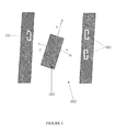
- FIG 1 a schematic representation of a setup of an indoor positioning system in accordance with an embodiment of the present invention is illustrated.
- This embodiment is based on the principle that when a magnetic dipole is passed through a magnetic field it is acted upon by a force based on the orientation of the magnetic field. Furthermore, the magnetic lines of force do not follow a straight line but rather an ellipsoid curvature is observed.
- three permanent/rare-earth magnets (101) are disposed on a doorway (103).
- the magnetometer When a person with a smartphone/mobile phone (102) comprising a 3-axis magnetometer sensor (considered analogous to three orthogonal magnetic dipoles) passes through the magnetic field created in the doorway due to the permanent/rare-earth magnets, the magnetometer records unique perturbations based on the direction of the motion, the orientation of the phone, the orientation of the field and the speed of motion, and generates corresponding signals.
- the magnets (101) are disposed on the walls adjacent to the doorway. In accordance with yet another embodiment, the magnets (101) are embedded within a frame associated with the doorway.
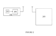
- a processor (202) within the smartphone/mobile phone (102) running a smartphone application reads the magnetometer (201) signals and extracts features/data which are wirelessly sent to a backend server (203).
- the backend server matches the extracted features/data with known sets of data using signal processing techniques whereby the doorway (103) and the smartphone/mobile phone (102) are identified to localize the person.
- the backend server (203) is typically deployed on a computing platform referred to as Real-Time Integrated Platform for Services & Analytics (RIPSAC) developed by the applicant.
- RIPSAC Real-Time Integrated Platform for Services & Analytics
- the phone major axis is always Y-axis.
- a person carrying a smartphone in an orientation whereby the Y-axis is aligned to the direction of motion causes the X-axis to be directly aligned in the direction of the magnetic field and Z-axis to be orthogonal to the magnetic field.
- magnetometer readings are obtained along all three axes.
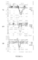
- FIG 3a a graphical representation of the magnetic lines of force based on orientation of the magnetic field created by a setup of three orthogonally placed permanent/rare-earth magnets is illustrated.
- FIG 3b a graphical representation of the magnetic lines of force based on orientation of the magnetic field created by a setup of three straight parallelly placed permanent/rare-earth magnets is illustrated.
- FIG 3c a graphical representation of the magnetic lines of force based on orientation of the magnetic field created by a setup of three slanting parallelly placed permanent/rare-earth magnets is illustrated.
- figure 3d a graphical representation of the magnetic lines of force based on orientation of the magnetic field created by a setup of three slanting concavo-convexly placed permanent/rare-earth magnets is illustrated.
- the magnetic lines of force differ as illustrated in each of the above referred figures when a person carrying a smartphone comprising a 3-axis magnetometer sensor passes through the magnetic field at slow speed (SS), medium speed (MS) and high speed (HS).
- SS slow speed
- MS medium speed
- HS high speed
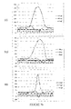
- FIG 4 a graphical representation of the magnetic lines of force based on orientation of the magnetic field created by a setup of three randomly placed permanent/rare-earth magnets is illustrated. The readings are significant in the Z-axis when the magnets are placed along vertically different locations along opposite panels.
- the aforementioned method of detecting and localizing a moving subject in an enclosed environment typically comprises the following steps:
- the method as disclosed herein above can also be implemented to determine orientation of the smartphone by using the SVM based classification method.
- the indoor positioning system of the present disclosure provides a mechanism by which magnetometer disturbances on a smartphone/mobile phone due to permanent magnets can be analyzed to provide magnetic identification of the doorways.
- This system and the implemented method are not affected by changes in environment as field due to permanent magnets is much stronger than disturbances in the geomagnetic field.
- the field properties of permanent/rare-earth magnets remain unaffected by changes in weather conditions.
- the technical advancements offered by the indoor positioning system of the present disclosure include the realization of:
Landscapes
- Engineering & Computer Science (AREA)
- Remote Sensing (AREA)
- Radar, Positioning & Navigation (AREA)
- Physics & Mathematics (AREA)
- Signal Processing (AREA)
- Computer Networks & Wireless Communication (AREA)
- General Physics & Mathematics (AREA)
- Condensed Matter Physics & Semiconductors (AREA)
- Automation & Control Theory (AREA)
- Position Fixing By Use Of Radio Waves (AREA)
- Navigation (AREA)
- Measurement Of Length, Angles, Or The Like Using Electric Or Magnetic Means (AREA)
- Radar Systems Or Details Thereof (AREA)
- Traffic Control Systems (AREA)
Abstract
Description
- The present disclosure relates to tracking and locating a person / object.
- The expression 'moving subject' used hereinafter in the specification refers to but is not limited to persons / objects moving through an enclosed environment.
- The expression 'opening' used hereinafter in the specification refers to but is not limited to walls having doorways, entrances, exits, room dividers and the like that may be utilized to provide access through an environment divided into various functional spaces.
- These definitions are in addition to those expressed in the art.
- Locating and/or tracking a person or an object in an indoor space or a confined area is typically referred to as indoor positioning, indoor localization, local positioning and the like. Indoor positioning is used for many applications such as locating or giving directions to tourists in an exhibition, locating doctors/nurses/medical equipment in a hospital, locating personnel as well as containers/merchandise in a large warehouse and the like.
- Systems employed for indoor positioning, as known in the art, are typically based on inertial navigation wherein these systems generally incorporate technologies such as Global Positioning System (GPS) based tracking, wireless/WiFi tracking using Radio Frequency (RF) communication and typically use sensors such as gyroscopes, accelerometers and electromagnetic field sensors for location detection. Typically a wireless communication device carried by a person or affixed onto an object, sends out wireless signals which are picked up by sensors placed at different locations within the indoor environment and used for locating and/or tracking the person/object. Some systems use beacons embedded in wireless communication devices that transmit/broadcast signals which are picked up by WiFi receivers placed at different locations in the indoor environment and are used to locate the person/object by mapping the indoor environment or via the GPS. Other systems use RFID tags affixed onto the object or carried by the person while moving around in the indoor environment. The RFID tags are detected by sensors placed at different locations when the person/object passes near the sensor whereupon the sensor signals are used to locate the person/object.
- Several endeavors have been made in this field for localizing a moving person / object. For instance,
US6393360 discloses a method of outdoor localization.WO/2013/065042 discloses a method of both indoor and outdoor localization using earth magnetic field readings and electromagnetic signals. -
JP2011033609 JP2011059091 US20120130632 discloses a system and method for locating, tracking, and/or monitoring the status of personnel and/or assets, both indoors and outdoors by deploying electromagnets. - Furthermore,
DE10127156 discloses a local positioning system for moving objects including people, animals or vehicles to determine if the object is in danger and automatically dials a number. The position determination by the system is based on calculation of distance between a transmitter on the body of the object and a receiver. Such calculations can be complicated and lead to errors especially if the path taken by the moving object is not necessarily linear. - Still further, IN21220 discloses a container tracking system used to track shipping containers in a storage and transfer yard. Three dimensional accelerometers are provided on moving containers and position determination is based on direction of movement and acceleration magnitude information.
- While indoor positioning systems known in the art can determine location of a person/object, need for a simple, accurate and robust system and method of localizing a moving subject is especially critical in emergency situations such as fire, water logging and the like to evacuate people from the indoor environment. As explained herein above, the systems known in the art use geo-magnetic field distortions in the indoor environment for location detection which are susceptible to change due to change in indoor environment as well as weather conditions. Alternatively, electro-magnetic sensors used in these systems incur significant infrastructural changes and associated costs.
- Thus there is a need for a system for locating a person or an object in an indoor environment that is free from disturbance due to environmental changes and from inertial navigation errors due to geo-magnetic field distortions and that can detect the orientation of the person/object.
- Some of the objects of the present disclosure aimed to ameliorate one or more problems of the prior art or to at least provide a useful alternative are listed herein below.
- An object of the present disclosure is to provide an indoor positioning system that can localize a person/object in an indoor environment.
- Another object of the present disclosure is to provide an indoor positioning system that can detect orientation and direction of the person/object.
- Yet another object of the present disclosure is to provide an indoor positioning system that is free from disturbance due to environmental changes.
- Still another object of the present disclosure is to provide an indoor positioning system that is free from inertial navigation errors.
- One more object of the present disclosure is to provide an indoor positioning system that does not incur infrastructural changes and is cost effective.
- Other objects and advantages of the present disclosure will be more apparent from the following description when read in conjunction with the accompanying figures, which are not intended to limit the scope of the present invention.
- In accordance with the present invention, there is provided an indoor positioning system for localizing a moving subject in an enclosed environment divided into functional spaces, said environment having at least one opening for providing access to said spaces, the system comprising:
- at least two permanent magnets disposed on the opening in a pre-determined orientation to create a unique magnetic field for each opening;
- a wireless communication unit associated with the moving subject, the wireless communication unit comprising:
- ■ at least one magnetometer sensor, the magnetometer sensor adapted to sense perturbations in each of the unique magnetic fields in the event that the moving subject passes through the openings, and generate signals corresponding to at least one parameter selected from the group consisting of:
- ◆ direction of motion of the moving subject,
- ◆ orientation of the wireless communication unit,
- ◆ orientation of the magnetic field and
- ◆ speed of motion of the moving subject; and
- ■ a processor adapted to receive the signals and extract data corresponding to the parameters; and
- ■ at least one magnetometer sensor, the magnetometer sensor adapted to sense perturbations in each of the unique magnetic fields in the event that the moving subject passes through the openings, and generate signals corresponding to at least one parameter selected from the group consisting of:
- a backend server wirelessly communicating with the wireless communication unit, the backend server adapted to process the data received from the wireless communication unit by using a pre-determined processing method to identify the opening and the wireless communication unit to localize the moving subject.
- The permanent magnets can be rare-earth magnets.
- Two or more permanent magnets can be placed at an opening in an orientation selected from the group consisting of orthogonal placement, straight parallel placement, slanting parallel placement, slanting concavo-convex placement and random placement with reference to each other.
- The wireless communications unit can be at least one of a smartphone and a mobile phone.
- The magnetometer sensor can be a three-axis magnetometer sensor.
- Further in accordance with the present disclosure, there is provided a method for localizing a moving subject in an enclosed environment divided into functional spaces, said environment having at least one opening for providing access to said spaces, said method comprising the following steps:
- positioning at least two magnets at each opening in a pre-determined orientation to create a magnetic field;
- sensing perturbations in the magnetic field along X, Y and Z axes and generating corresponding signals;
- receiving the signals and extracting associated data;
- communicating the data;
- processing the communicated data by using a pre-determined processing method to identify an opening and localize the moving subject.
- The step of processing the communicated data by using a pre-determined processing method may further comprise the following steps:
- computing absolute value of a pre-determined sample of data along the X-axis;
- detecting peak/trough of the data sample along the X-axis;
- comparing the peak of the data sample along the X-axis with the peak of a base data to determine the direction of motion of the moving subject along two directions, the directions being along the magnetic field or against the magnetic field;
- determining width of the peak/trough of the data sample along the X-axis;
- performing data mining on the data sample along X, Y and Z axes by a cluster analysis method to determine Region of Interest (ROI);
- performing Time Domain Normalization (TDN) on the data sample along with the data sample along Y-axis and Z-axis over the ROI to obtain normalized data for Y-axis and Z-axis;
- performing Discrete Wavelet Transform (DWT) on the normalized data for Y-axis and Z-axis; and
- classifying the DWT coefficients of the Y-axis and Z-axis by using a pre-determined classification method to localize the moving subject.
- Additionally, the step of performing data mining may include the following steps:
- performing 2-cluster k-means clustering on the data sample along X, Y and Z axes; and
- utilizing the maxima and minima of the data sample along X, Y and Z axes.
- The classification method can be Support Vector Machine (SVM) based classification method.
- An example indoor positioning system in accordance with the present invention will now be described with the help of the accompanying drawings, in which:
-
Figure 1 is a schematic representation illustrating a setup of an indoor positioning system in accordance with an embodiment of the present invention; -
Figure 2 is a schematic representation illustrating an indoor positioning system of the present invention; -
Figures 3a ,3b ,3c and3d illustrate graphical representations of magnetic lines of forces when magnets disposed on a doorway are oriented in different directions; -
Figure 4 is a graphical representation illustrating magnetic lines of force when magnets disposed on a doorway are oriented randomly; and -
Figures 5a and5b illustrate a flow chart depicting the steps involved in a method of detecting and localizing a moving subject in an enclosed environment in accordance with one embodiment of the present invention. - Systems employed for locating and/or tracking a person or an object in an indoor space or a confined area are typically based on inertial navigation techniques. These systems generally incorporate technologies such as Global Positioning System (GPS) based tracking or wireless/WiFi tracking using Radio Frequency (RF) communication and typically use sensors such as gyroscopes, accelerometers, electromagnetic field sensors, and the like for location detection. Although inertial navigation is a low-power and low cost method of localizing people in indoor environments, the problem with this approach is that it suffers from drift and spread due to sensor errors. Efforts to reduce such errors using methods such as particle filter based on floor plan, suffer from issues when there are few closed spaces. Hence some means of anchoring is needed. RF based anchoring needs modification of the infrastructure which involves cost and may not be practically feasible in home scenarios. Hence, inertial indoor localization still has unsolved problems that need to be addressed.
- Furthermore, these systems typically implement geo-magnetic field modeling techniques for location detection. However, modeling of the geo-magnetic field is susceptible to change with changes in weather and indoor environment (such as movement of furniture etc.). Moreover, these systems determine the location of the person/object without accounting for information in relation to orientation and direction of the person/object.
- Thus to overcome these aforementioned limitations, the present disclosure envisages an indoor positioning system and method of localizing a person / object in an indoor environment by detecting the orientation and direction of the person/object to provide a true location of the person/object without navigation errors.
- The system herein and the various features and advantageous details thereof are explained with reference to the non-limiting embodiments in the following description. Descriptions of well-known components and processing techniques are omitted so as to not unnecessarily obscure the embodiments herein. The examples used herein are intended merely to facilitate an understanding of ways in which the embodiments herein may be practiced and to further enable those of skill in the art to practice the embodiments herein. Accordingly, the examples should not be construed as limiting the scope of the invention.
- The indoor positioning system of the present disclosure will now be described with reference to the embodiments shown in the accompanying drawings. The embodiments do not limit the scope and ambit of the disclosure. The description relates purely to the examples and preferred embodiments of the disclosed tool and its suggested applications.
- The indoor positioning system of the present disclosure is explained herein after with reference to localizing a moving subject in an indoor / enclosed environment divided into functional spaces and having openings at various locations for providing access to the functional spaces. The moving subject being a person and the opening being a doorway is purely for ease of explanation.
- The indoor positioning system of the present disclosure implements a method of localizing a person in an indoor environment wherein a magnetometer in a wireless communication unit, typically a smartphone/mobile phone, interacts with externally deployed magnets in 3D space, preferably on a doorway, and provides a unique magnetic identification of the location. The indoor positioning method of the present disclosure is based on permanent magnets which can be used for preparing anchor points in the indoor environment that can be used to correct inertial navigation errors. The indoor positioning system of the present disclosure includes deploying multiple magnets on a doorway in a known orientation to create a unique magnetic field. Typically at least two magnets are disposed on the doorway. When a person carrying the smartphone/mobile phone in a specific orientation passes through the doorway, the magnetometer signals produce perturbations based on the field in 3D space. By fingerprinting these perturbations, the doors can be identified uniquely thereby localizing the person.
- Referring to
figure 1 , a schematic representation of a setup of an indoor positioning system in accordance with an embodiment of the present invention is illustrated. This embodiment is based on the principle that when a magnetic dipole is passed through a magnetic field it is acted upon by a force based on the orientation of the magnetic field. Furthermore, the magnetic lines of force do not follow a straight line but rather an ellipsoid curvature is observed. In accordance with an exemplary embodiment, three permanent/rare-earth magnets (101) are disposed on a doorway (103). When a person with a smartphone/mobile phone (102) comprising a 3-axis magnetometer sensor (considered analogous to three orthogonal magnetic dipoles) passes through the magnetic field created in the doorway due to the permanent/rare-earth magnets, the magnetometer records unique perturbations based on the direction of the motion, the orientation of the phone, the orientation of the field and the speed of motion, and generates corresponding signals. - In accordance with another embodiment, the magnets (101) are disposed on the walls adjacent to the doorway. In accordance with yet another embodiment, the magnets (101) are embedded within a frame associated with the doorway.
- Referring to
figure 2 , a schematic representation of the indoor positioning system of the present disclosure is illustrated. A processor (202) within the smartphone/mobile phone (102) running a smartphone application reads the magnetometer (201) signals and extracts features/data which are wirelessly sent to a backend server (203). The backend server matches the extracted features/data with known sets of data using signal processing techniques whereby the doorway (103) and the smartphone/mobile phone (102) are identified to localize the person. The backend server (203) is typically deployed on a computing platform referred to as Real-Time Integrated Platform for Services & Analytics (RIPSAC) developed by the applicant. - Typically, in android based smartphones, the phone major axis is always Y-axis. Hence, a person carrying a smartphone in an orientation whereby the Y-axis is aligned to the direction of motion causes the X-axis to be directly aligned in the direction of the magnetic field and Z-axis to be orthogonal to the magnetic field. However, since magnetic lines of force do not travel in a straight line, magnetometer readings are obtained along all three axes.
- Referring to
figure 3a , a graphical representation of the magnetic lines of force based on orientation of the magnetic field created by a setup of three orthogonally placed permanent/rare-earth magnets is illustrated. Referring tofigure 3b , a graphical representation of the magnetic lines of force based on orientation of the magnetic field created by a setup of three straight parallelly placed permanent/rare-earth magnets is illustrated. Referring tofigure 3c , a graphical representation of the magnetic lines of force based on orientation of the magnetic field created by a setup of three slanting parallelly placed permanent/rare-earth magnets is illustrated. Referring tofigure 3d , a graphical representation of the magnetic lines of force based on orientation of the magnetic field created by a setup of three slanting concavo-convexly placed permanent/rare-earth magnets is illustrated. - The magnetic lines of force differ as illustrated in each of the above referred figures when a person carrying a smartphone comprising a 3-axis magnetometer sensor passes through the magnetic field at slow speed (SS), medium speed (MS) and high speed (HS).
- As seen in
figures 3a ,3b ,3c and3d , the speed factor only causes broadening of the peak signals and hence the orientations can be identified even if one person travels faster or slower than the other. Accordingly the method of detection is based on "wavelet analysis" which takes into account this factor of broadening or narrowing of peaks. Furthermore, it should be noted that one single peak is seen on X-axis as expected, however the Y-axis shows unique "signature" for each orientation and hence can be used for characterization. Thus, with two magnets 22 = 4 different configurations can be achieved. Similarly by using more number of magnets, even more number of uniquely identifiable signatures can be achieved. Notably, if the direction of motion of the person changes, the direction of the field changes as well, thereby converting the peaks into troughs. However the signal signature remains similar and can be detected uniquely. Thus this method enables determining whether the person was entering or exiting the room. - Referring to
figure 4 , a graphical representation of the magnetic lines of force based on orientation of the magnetic field created by a setup of three randomly placed permanent/rare-earth magnets is illustrated. The readings are significant in the Z-axis when the magnets are placed along vertically different locations along opposite panels. - Referring to
figures 5a and5b , the aforementioned method of detecting and localizing a moving subject in an enclosed environment typically comprises the following steps: - computing absolute value of a pre-determined sample of a data along the X-axis;
- detecting peak/trough of the data sample along the X-axis;
- comparing the peak of the data sample along the X-axis with the peak of a base signal to determine the direction of motion of the moving subject/smartphone, wherein typically the direction of motion of the moving subject/smartphone is along the magnetic field upon detecting that the peak of the original signal is positive and against the magnetic field upon detecting that the peak of the original signal is negative;
- determining thickness/width of the peak/trough of the data sample along the X-axis, wherein typically the thickness/width of the peak/trough of the data sample is inversely proportional to the speed of the moving subject through the portioning means;
- performing data mining on the data sample along X, Y and Z axes by a cluster analysis method to determine Region of Interest (ROI), wherein the step of data mining includes:
- ■ performing 2-cluster k-means clustering on the data sample along X, Y and Z axes; and
- ■ utilizing the maxima and minima of the data sample along X, Y and Z axes to determine ROI for processing.
- performing Time Domain Normalization (TDN) on the data sample along with the data sample along Y-axis and Z-axis over the ROI to obtain normalized signals for Y-axis and Z-axis;
- performing Discrete Wavelet Transform (DWT) on the normalized signals for Y-axis and Z-axis; and
- classifying the DWT coefficients of the Y-axis and Z-axis by using a pre-determined classification method, into a pre-defined identification of the doorway to localize the moving subject, wherein typically the classification method is Support Vector Machine (SVM) based classification method.
- Furthermore, the method as disclosed herein above can also be implemented to determine orientation of the smartphone by using the SVM based classification method.
- Thus, the indoor positioning system of the present disclosure provides a mechanism by which magnetometer disturbances on a smartphone/mobile phone due to permanent magnets can be analyzed to provide magnetic identification of the doorways. This system and the implemented method are not affected by changes in environment as field due to permanent magnets is much stronger than disturbances in the geomagnetic field. Furthermore, the field properties of permanent/rare-earth magnets remain unaffected by changes in weather conditions.
- The technical advancements offered by the indoor positioning system of the present disclosure include the realization of:
- localizing a person/object in an indoor environment;
- detecting the orientation and direction of the person/object;
- independence from disturbances due to environmental changes;
- elimination of inertial navigation errors; and
- no incurrence of infrastructural changes and cost effectiveness.
- Throughout this specification the word "comprise", or variations such as "comprises" or "comprising", will be understood to imply the inclusion of a stated element, integer or step, or group of elements, integers or steps, but not the exclusion of any other element, integer or step, or group of elements, integers or steps.
- The use of the expression "at least" or "at least one" suggests the use of one or more elements or ingredients or quantities, as the use may be in the embodiment of the invention to achieve one or more of the desired objects or results.
- Any discussion of documents, materials, devices, articles or the like that has been included in this specification is solely for the purpose of providing a context for the invention. It is not to be taken as an admission that any or all of these matters form part of the prior art base or were common general knowledge in the field relevant to the invention as it existed anywhere before the priority date of this application.
- The numerical values mentioned for the various physical parameters, dimensions or quantities are only approximations and it is envisaged that the values higher/lower than the numerical values assigned to the parameters, dimensions or quantities fall within the scope of the invention, unless there is a statement in the specification specific to the contrary.
- The foregoing description of the specific embodiments will so fully reveal the general nature of the embodiments herein that others can, by applying current knowledge, readily modify and/or adapt for various applications such specific embodiments without departing from the generic concept, and, therefore, such adaptations and modifications should and are intended to be comprehended within the meaning and range of equivalents of the disclosed embodiments. It is to be understood that the phraseology or terminology employed herein is for the purpose of description and not of limitation. Therefore, while the embodiments herein have been described in terms of preferred embodiments, those skilled in the art will recognize that the embodiments herein can be practiced with modification within the scope of the invention, which is defined by the claims.
Claims (9)
- An indoor positioning system for localizing a moving subject in an enclosed environment divided into functional spaces, said environment having at least one opening for providing access to said functional spaces, said system comprising:• at least two permanent magnets disposed on the opening in a pre-determined orientation to create a unique magnetic field for each opening;• a wireless communication unit associated with the moving subject, said wireless communication unit comprising:■ at least one magnetometer sensor, said magnetometer sensor adapted to sense perturbations in each of said unique magnetic fields in the event that the moving subject passes through the openings, and generate signals corresponding to at least one parameter selected from the group consisting of:◆ direction of motion of the moving subject,◆ orientation of said wireless communication unit,◆ orientation of said magnetic field and◆ speed of motion of the moving subject; and■ a processor adapted to receive said signals and extract data corresponding to said parameters;• a backend server wirelessly communicating with said wireless communication unit, said backend server adapted to process said data received from said wireless communication unit by using a pre-determined processing method to identify the openings and said wireless communication unit to localize the moving subject.
- The indoor positioning system as claimed in claim 1, wherein said permanent magnets are rare-earth magnets.
- The indoor positioning system as claimed in claim 1 or 2, wherein at least two permanent magnets are placed at an opening in an orientation selected from the group consisting of orthogonal placement, straight parallel placement, slanting parallel placement, slanting concavo-convex placement and random placement with reference to each other.
- The indoor positioning system as claimed in claim 1, 2 or 3, wherein said wireless communications unit is at least one of a smartphone and a mobile phone.
- The indoor positioning system as claimed in claim 1, 2, 3 or 4, wherein said magnetometer sensor is a three-axis magnetometer sensor.
- A method for localizing a moving subject in an enclosed environment divided into functional spaces, said environment having at least one opening for providing access to said spaces, said method comprising the following steps:• positioning at least two magnets at each opening in a pre-determined orientation to create a magnetic field;• sensing perturbations in the magnetic field along X, Y and Z axes and generating corresponding signals;• receiving said signals and extracting associated data;• communicating said data to a processor ;• processing the communicated data by using a pre-determined processing method to identify an opening and localize the moving subject.
- The method as claimed in claim 6, wherein the step of processing said communicated data by using a pre-determined processing method further comprises the following steps:• computing absolute value of a pre-determined sample of data along the X-axis;• detecting peak/trough of said data sample along the X-axis;• comparing the peak of said data sample along the X-axis with the peak of a base data to determine the direction of motion of the moving subject along two directions, said directions being along the magnetic field or against the magnetic field;• determining width of the peak/trough of said data sample along the X-axis;• performing data mining on said data sample along X, Y and Z axes by a cluster analysis method to determine Region of Interest (ROI);• performing Time Domain Normalization (TDN) on said data sample along with the data sample along Y-axis and Z-axis over said ROI to obtain normalized data for Y-axis and Z-axis;• performing Discrete Wavelet Transform (DWT) on the normalized data for Y-axis and Z-axis; and• classifying the DWT coefficients of the Y-axis and Z-axis by using a pre-determined classification method to localize the moving subject.
- The method as claimed in claim 7, wherein the step of performing data mining includes the following steps:• performing 2-cluster k-means clustering on said data sample along X, Y and Z axes; and• utilizing the maxima and minima of said data sample along X, Y and Z axes.
- The method as claimed in claim 7 or 8, wherein said classification method is Support Vector Machine (SVM) based classification method.
Applications Claiming Priority (1)
| Application Number | Priority Date | Filing Date | Title |
|---|---|---|---|
| IN2571MU2013 IN2013MU02571A (en) | 2013-08-05 | 2013-08-05 |
Publications (2)
| Publication Number | Publication Date |
|---|---|
| EP2835615A1 true EP2835615A1 (en) | 2015-02-11 |
| EP2835615B1 EP2835615B1 (en) | 2019-10-09 |
Family
ID=54199318
Family Applications (1)
| Application Number | Title | Priority Date | Filing Date |
|---|---|---|---|
| EP14179884.3A Active EP2835615B1 (en) | 2013-08-05 | 2014-08-05 | An indoor positioning system |
Country Status (5)
| Country | Link |
|---|---|
| US (1) | US9557178B2 (en) |
| EP (1) | EP2835615B1 (en) |
| JP (1) | JP6285316B2 (en) |
| AU (1) | AU2014208283B2 (en) |
| IN (1) | IN2013MU02571A (en) |
Families Citing this family (30)
| Publication number | Priority date | Publication date | Assignee | Title |
|---|---|---|---|---|
| FI124153B (en) * | 2012-01-11 | 2014-04-15 | Indooratlas Oy | Use of magnetic field-based navigation |
| JP6675677B2 (en) * | 2015-07-06 | 2020-04-01 | 株式会社Nttドコモ | Position detection system |
| US9924373B2 (en) | 2015-09-21 | 2018-03-20 | International Business Machines Corporation | Adaptively position objects through mobile signal sources |
| US10129698B2 (en) | 2016-07-14 | 2018-11-13 | United Parcel Service Of America, Inc. | Internal location address and automatic routing of intra-facility movement |
| US10015638B2 (en) | 2016-07-28 | 2018-07-03 | Carbyne Ltd. | System and method for providing a descriptive location of a user device |
| RU2623829C1 (en) * | 2016-10-21 | 2017-06-29 | Марина Владимировна Медведева | Adaptive method for displacement measurement |
| US11003916B2 (en) | 2017-11-03 | 2021-05-11 | Toyota Research Institute, Inc. | Systems and methods for object historical association |
| US10165407B1 (en) | 2018-01-04 | 2018-12-25 | Mapsted Corp. | Magnetic landmark method and system for detecting in-building (local venue) threshold |
| WO2020020535A1 (en) | 2018-07-25 | 2020-01-30 | Robert Bosch Gmbh | A method of configuring a plurality of position co-ordinates for indoor positioning |
| US11408966B2 (en) | 2018-11-14 | 2022-08-09 | International Business Machines Corporation | Location detection using a single beacon |
| US10820149B2 (en) | 2019-01-25 | 2020-10-27 | Mapsted Corp. | Method and system for mobile device dual stream localization in a magnetic distortion region |
| US10816343B2 (en) | 2019-01-25 | 2020-10-27 | Mapsted Corp. | Method and system for deploying crowd-sourced magnetic distortion rejection map |
| US10634505B1 (en) | 2019-02-07 | 2020-04-28 | Mapsted Corp. | Method and system for threshold-based detection of distortive magnetic fields in indoor locations |
| US11428533B2 (en) | 2019-07-04 | 2022-08-30 | Mapsted Corp. | Generating magnetic fingerprint for mobile device indoor navigation |
| US11473915B2 (en) | 2019-07-04 | 2022-10-18 | Mapsted Corp. | Magnetic fingerprint neural network training for mobile device indoor navigation |
| CN110324781B (en) * | 2019-07-16 | 2020-08-21 | 拉扎斯网络科技(上海)有限公司 | Indoor positioning method, device, electronic device, and computer-readable storage medium |
| US11402233B2 (en) | 2019-07-23 | 2022-08-02 | Mapsted Corp. | Maintaining a trained neural network in magnetic fingerprint based indoor navigation |
| US11512961B2 (en) | 2019-07-26 | 2022-11-29 | Mapsted Corp. | Deployment of trained neural network in magnetic fingerprint based indoor navigation |
| US11435189B2 (en) | 2019-09-04 | 2022-09-06 | Mapsted Corp. | Method and system of crowd- sourced magnetic fingerprinting with neural network re-training |
| US10823573B1 (en) | 2019-09-04 | 2020-11-03 | Mapsted Corp. | Method and system for lightweight calibration of magnetic fingerprint dataset |
| CN110657807B (en) * | 2019-09-30 | 2022-09-23 | 西安电子科技大学 | Indoor positioning displacement measurement method for detecting discontinuity based on wavelet transformation |
| US11525686B2 (en) | 2019-09-30 | 2022-12-13 | Mapsted Corp. | Crowd sourced multi-stage mobile device fingerprint based navigation |
| US10837784B1 (en) | 2019-11-01 | 2020-11-17 | Mapsted Corp. | Magnetic parameter-based localization in mobile device navigation |
| US11175144B2 (en) | 2019-11-01 | 2021-11-16 | Mapsted Corp. | Magnetic parameter-based localization in mobile device navigation |
| US10890450B1 (en) | 2020-01-30 | 2021-01-12 | Mapsted Corp. | Infrastructure re-purposed magnetic signature in mobile device localization |
| CN112113528B (en) * | 2020-09-21 | 2025-02-18 | 河钢股份有限公司承德分公司 | Track wear automatic detection marking vehicle and use method thereof |
| US11218839B1 (en) | 2020-10-05 | 2022-01-04 | Mapsted Corp. | Method and system for zone-based localization of mobile devices |
| JP2024000613A (en) * | 2022-06-21 | 2024-01-09 | 旭化成エレクトロニクス株式会社 | Estimation device, estimation method, and program |
| CN118049991A (en) * | 2024-02-18 | 2024-05-17 | 安徽大学 | A method and system for tracking activity trajectories of elderly people at home |
| CN118758316B (en) * | 2024-09-02 | 2025-01-14 | 天津航天中为数据系统科技有限公司 | A method for improving the positioning accuracy of unmanned aerial vehicle for observation targets |
Citations (11)
| Publication number | Priority date | Publication date | Assignee | Title |
|---|---|---|---|---|
| US5369591A (en) * | 1993-03-11 | 1994-11-29 | Broxmeyer; Charles | Vehicle longitudinal control and collision avoidance system for an automated highway system |
| US6393360B1 (en) | 1999-11-17 | 2002-05-21 | Erjian Ma | System for automatically locating and directing a vehicle |
| DE10127156A1 (en) | 2001-06-02 | 2002-12-05 | Peter Daublebsky | Local positioning system for moving objects such as people, animals or vehicles determines if person is in danger and automatically dials number |
| US20060261772A1 (en) * | 2005-05-17 | 2006-11-23 | Lg Electronics Inc. | Position-recognizing system for self-moving robot |
| JP2011033609A (en) | 2009-07-31 | 2011-02-17 | Aichi Micro Intelligent Corp | Indoor position detector |
| JP2011059091A (en) | 2009-09-07 | 2011-03-24 | Aichi Micro Intelligent Corp | Apparatus for detecting indoor position |
| US20120130632A1 (en) | 2007-08-06 | 2012-05-24 | Amrit Bandyopadhyay | System and method for locating, tracking, and/or monitoring the status of personnel and/or assets both indoors and outdoors |
| US20120232838A1 (en) * | 2009-11-24 | 2012-09-13 | Nokia Corporation | Installation of Magnetic Signal Sources for Positioning |
| WO2013008124A1 (en) * | 2011-07-11 | 2013-01-17 | Nokia Corporation | Data routing for positioning |
| WO2013065042A1 (en) | 2011-11-02 | 2013-05-10 | Ronen Shai | Generating and using a location fingerprinting map |
| EP2613124A2 (en) * | 2012-01-09 | 2013-07-10 | Honeywell International Inc. | Robust method for signal segmentation for motion classification in personal navigation |
Family Cites Families (6)
| Publication number | Priority date | Publication date | Assignee | Title |
|---|---|---|---|---|
| DE102005026788A1 (en) * | 2005-06-10 | 2006-12-21 | Deutsche Telekom Ag | Method and system for locating a mobile WLAN client |
| US20070139195A1 (en) * | 2005-12-19 | 2007-06-21 | Yucheng Jin | Security system employing a hall effect sensor |
| US20120143495A1 (en) * | 2010-10-14 | 2012-06-07 | The University Of North Texas | Methods and systems for indoor navigation |
| DE102011079187A1 (en) * | 2011-07-14 | 2013-01-17 | Bayerische Motoren Werke Aktiengesellschaft | Method and apparatus for step detection of a pedestrian for a portable terminal |
| US9243918B2 (en) * | 2011-12-22 | 2016-01-26 | AppLabz, LLC | Systems, methods, and apparatus for providing indoor navigation using magnetic sensors |
| US9170112B2 (en) * | 2013-02-08 | 2015-10-27 | Google Inc. | Mobile device position and orientation from multiple unsurveyed magnetic sources |
-
2013
- 2013-08-05 IN IN2571MU2013 patent/IN2013MU02571A/en unknown
-
2014
- 2014-08-01 AU AU2014208283A patent/AU2014208283B2/en active Active
- 2014-08-04 US US14/450,890 patent/US9557178B2/en active Active
- 2014-08-05 JP JP2014159158A patent/JP6285316B2/en active Active
- 2014-08-05 EP EP14179884.3A patent/EP2835615B1/en active Active
Patent Citations (11)
| Publication number | Priority date | Publication date | Assignee | Title |
|---|---|---|---|---|
| US5369591A (en) * | 1993-03-11 | 1994-11-29 | Broxmeyer; Charles | Vehicle longitudinal control and collision avoidance system for an automated highway system |
| US6393360B1 (en) | 1999-11-17 | 2002-05-21 | Erjian Ma | System for automatically locating and directing a vehicle |
| DE10127156A1 (en) | 2001-06-02 | 2002-12-05 | Peter Daublebsky | Local positioning system for moving objects such as people, animals or vehicles determines if person is in danger and automatically dials number |
| US20060261772A1 (en) * | 2005-05-17 | 2006-11-23 | Lg Electronics Inc. | Position-recognizing system for self-moving robot |
| US20120130632A1 (en) | 2007-08-06 | 2012-05-24 | Amrit Bandyopadhyay | System and method for locating, tracking, and/or monitoring the status of personnel and/or assets both indoors and outdoors |
| JP2011033609A (en) | 2009-07-31 | 2011-02-17 | Aichi Micro Intelligent Corp | Indoor position detector |
| JP2011059091A (en) | 2009-09-07 | 2011-03-24 | Aichi Micro Intelligent Corp | Apparatus for detecting indoor position |
| US20120232838A1 (en) * | 2009-11-24 | 2012-09-13 | Nokia Corporation | Installation of Magnetic Signal Sources for Positioning |
| WO2013008124A1 (en) * | 2011-07-11 | 2013-01-17 | Nokia Corporation | Data routing for positioning |
| WO2013065042A1 (en) | 2011-11-02 | 2013-05-10 | Ronen Shai | Generating and using a location fingerprinting map |
| EP2613124A2 (en) * | 2012-01-09 | 2013-07-10 | Honeywell International Inc. | Robust method for signal segmentation for motion classification in personal navigation |
Also Published As
| Publication number | Publication date |
|---|---|
| AU2014208283B2 (en) | 2017-11-30 |
| EP2835615B1 (en) | 2019-10-09 |
| US9557178B2 (en) | 2017-01-31 |
| JP2015031698A (en) | 2015-02-16 |
| US20150039226A1 (en) | 2015-02-05 |
| IN2013MU02571A (en) | 2015-06-12 |
| JP6285316B2 (en) | 2018-02-28 |
| AU2014208283A1 (en) | 2015-02-19 |
Similar Documents
| Publication | Publication Date | Title |
|---|---|---|
| AU2014208283B2 (en) | An indoor positioning system | |
| CN107923960B (en) | System and method for locating labels in space | |
| US20140365119A1 (en) | Detecting information about motion of mobile device | |
| US20150119086A1 (en) | Simultaneous localization and mapping systems and methods | |
| US20150198443A1 (en) | Localization activity classification systems and methods | |
| US10134253B2 (en) | Systems and methods for locating and determining the orientation of a handheld device | |
| US20070168127A1 (en) | Location and tracking system, method and device using wireless technology | |
| De Cillis et al. | Hybrid indoor positioning system for first responders | |
| Zhu et al. | Survey of indoor positioning technologies and systems | |
| CN109084753A (en) | Position determining means and method, mobile device and computer readable recording medium | |
| JP2015031698A5 (en) | ||
| Ahmed et al. | Smartevactrak: A people counting and coarse-level localization solution for efficient evacuation of large buildings | |
| EP3920794B1 (en) | Indoor occupancy estimation, trajectory tracking and event monitoring and tracking system | |
| Yoon et al. | Victim localization and assessment system for emergency responders | |
| Hayward et al. | A novel inertial positioning update method, using passive RFID tags, for indoor asset localisation | |
| CN113366370A (en) | System, method and apparatus for locating objects | |
| US11029161B2 (en) | Position determination device and method | |
| Wei et al. | iMag+: An accurate and rapidly deployable inertial magneto-inductive SLAM system | |
| Zhao et al. | A battery-free object localization and motion sensing platform | |
| Moder et al. | Indoor positioning for visually impaired people based on smartphones | |
| WO2018038970A1 (en) | Systems and methods for locating items within a facility | |
| Galván-Tejada et al. | Magnetic-field feature extraction for indoor location estimation | |
| Chiba et al. | Three-dimensional localization of a rotating magnetic dipole from the Fourier integrals of its magnetic flux density with acceleration data | |
| TW201445451A (en) | Electronic apparatus, method and system for measuring location | |
| Chehreghan et al. | Infrastructure-free indoor navigation based on smartphone sensors in smart buildings |
Legal Events
| Date | Code | Title | Description |
|---|---|---|---|
| PUAI | Public reference made under article 153(3) epc to a published international application that has entered the european phase |
Free format text: ORIGINAL CODE: 0009012 |
|
| 17P | Request for examination filed |
Effective date: 20140805 |
|
| AK | Designated contracting states |
Kind code of ref document: A1 Designated state(s): AL AT BE BG CH CY CZ DE DK EE ES FI FR GB GR HR HU IE IS IT LI LT LU LV MC MK MT NL NO PL PT RO RS SE SI SK SM TR |
|
| AX | Request for extension of the european patent |
Extension state: BA ME |
|
| R17P | Request for examination filed (corrected) |
Effective date: 20150811 |
|
| RBV | Designated contracting states (corrected) |
Designated state(s): AL AT BE BG CH CY CZ DE DK EE ES FI FR GB GR HR HU IE IS IT LI LT LU LV MC MK MT NL NO PL PT RO RS SE SI SK SM TR |
|
| 17Q | First examination report despatched |
Effective date: 20161006 |
|
| STAA | Information on the status of an ep patent application or granted ep patent |
Free format text: STATUS: EXAMINATION IS IN PROGRESS |
|
| RIC1 | Information provided on ipc code assigned before grant |
Ipc: G01C 21/20 20060101AFI20190109BHEP Ipc: G01R 33/038 20060101ALI20190109BHEP Ipc: G05D 1/02 20060101ALI20190109BHEP |
|
| GRAP | Despatch of communication of intention to grant a patent |
Free format text: ORIGINAL CODE: EPIDOSNIGR1 |
|
| STAA | Information on the status of an ep patent application or granted ep patent |
Free format text: STATUS: GRANT OF PATENT IS INTENDED |
|
| INTG | Intention to grant announced |
Effective date: 20190226 |
|
| GRAS | Grant fee paid |
Free format text: ORIGINAL CODE: EPIDOSNIGR3 |
|
| GRAA | (expected) grant |
Free format text: ORIGINAL CODE: 0009210 |
|
| STAA | Information on the status of an ep patent application or granted ep patent |
Free format text: STATUS: THE PATENT HAS BEEN GRANTED |
|
| AK | Designated contracting states |
Kind code of ref document: B1 Designated state(s): AL AT BE BG CH CY CZ DE DK EE ES FI FR GB GR HR HU IE IS IT LI LT LU LV MC MK MT NL NO PL PT RO RS SE SI SK SM TR |
|
| REG | Reference to a national code |
Ref country code: GB Ref legal event code: FG4D |
|
| REG | Reference to a national code |
Ref country code: CH Ref legal event code: EP |
|
| REG | Reference to a national code |
Ref country code: IE Ref legal event code: FG4D |
|
| REG | Reference to a national code |
Ref country code: DE Ref legal event code: R096 Ref document number: 602014054814 Country of ref document: DE |
|
| REG | Reference to a national code |
Ref country code: AT Ref legal event code: REF Ref document number: 1189352 Country of ref document: AT Kind code of ref document: T Effective date: 20191115 |
|
| REG | Reference to a national code |
Ref country code: NL Ref legal event code: FP |
|
| REG | Reference to a national code |
Ref country code: LT Ref legal event code: MG4D |
|
| REG | Reference to a national code |
Ref country code: AT Ref legal event code: MK05 Ref document number: 1189352 Country of ref document: AT Kind code of ref document: T Effective date: 20191009 |
|
| PG25 | Lapsed in a contracting state [announced via postgrant information from national office to epo] |
Ref country code: PL Free format text: LAPSE BECAUSE OF FAILURE TO SUBMIT A TRANSLATION OF THE DESCRIPTION OR TO PAY THE FEE WITHIN THE PRESCRIBED TIME-LIMIT Effective date: 20191009 Ref country code: LV Free format text: LAPSE BECAUSE OF FAILURE TO SUBMIT A TRANSLATION OF THE DESCRIPTION OR TO PAY THE FEE WITHIN THE PRESCRIBED TIME-LIMIT Effective date: 20191009 Ref country code: SE Free format text: LAPSE BECAUSE OF FAILURE TO SUBMIT A TRANSLATION OF THE DESCRIPTION OR TO PAY THE FEE WITHIN THE PRESCRIBED TIME-LIMIT Effective date: 20191009 Ref country code: PT Free format text: LAPSE BECAUSE OF FAILURE TO SUBMIT A TRANSLATION OF THE DESCRIPTION OR TO PAY THE FEE WITHIN THE PRESCRIBED TIME-LIMIT Effective date: 20200210 Ref country code: ES Free format text: LAPSE BECAUSE OF FAILURE TO SUBMIT A TRANSLATION OF THE DESCRIPTION OR TO PAY THE FEE WITHIN THE PRESCRIBED TIME-LIMIT Effective date: 20191009 Ref country code: GR Free format text: LAPSE BECAUSE OF FAILURE TO SUBMIT A TRANSLATION OF THE DESCRIPTION OR TO PAY THE FEE WITHIN THE PRESCRIBED TIME-LIMIT Effective date: 20200110 Ref country code: AT Free format text: LAPSE BECAUSE OF FAILURE TO SUBMIT A TRANSLATION OF THE DESCRIPTION OR TO PAY THE FEE WITHIN THE PRESCRIBED TIME-LIMIT Effective date: 20191009 Ref country code: BG Free format text: LAPSE BECAUSE OF FAILURE TO SUBMIT A TRANSLATION OF THE DESCRIPTION OR TO PAY THE FEE WITHIN THE PRESCRIBED TIME-LIMIT Effective date: 20200109 Ref country code: LT Free format text: LAPSE BECAUSE OF FAILURE TO SUBMIT A TRANSLATION OF THE DESCRIPTION OR TO PAY THE FEE WITHIN THE PRESCRIBED TIME-LIMIT Effective date: 20191009 Ref country code: FI Free format text: LAPSE BECAUSE OF FAILURE TO SUBMIT A TRANSLATION OF THE DESCRIPTION OR TO PAY THE FEE WITHIN THE PRESCRIBED TIME-LIMIT Effective date: 20191009 Ref country code: NO Free format text: LAPSE BECAUSE OF FAILURE TO SUBMIT A TRANSLATION OF THE DESCRIPTION OR TO PAY THE FEE WITHIN THE PRESCRIBED TIME-LIMIT Effective date: 20200109 |
|
| PG25 | Lapsed in a contracting state [announced via postgrant information from national office to epo] |
Ref country code: RS Free format text: LAPSE BECAUSE OF FAILURE TO SUBMIT A TRANSLATION OF THE DESCRIPTION OR TO PAY THE FEE WITHIN THE PRESCRIBED TIME-LIMIT Effective date: 20191009 Ref country code: HR Free format text: LAPSE BECAUSE OF FAILURE TO SUBMIT A TRANSLATION OF THE DESCRIPTION OR TO PAY THE FEE WITHIN THE PRESCRIBED TIME-LIMIT Effective date: 20191009 Ref country code: IS Free format text: LAPSE BECAUSE OF FAILURE TO SUBMIT A TRANSLATION OF THE DESCRIPTION OR TO PAY THE FEE WITHIN THE PRESCRIBED TIME-LIMIT Effective date: 20200224 |
|
| PG25 | Lapsed in a contracting state [announced via postgrant information from national office to epo] |
Ref country code: AL Free format text: LAPSE BECAUSE OF FAILURE TO SUBMIT A TRANSLATION OF THE DESCRIPTION OR TO PAY THE FEE WITHIN THE PRESCRIBED TIME-LIMIT Effective date: 20191009 |
|
| REG | Reference to a national code |
Ref country code: DE Ref legal event code: R097 Ref document number: 602014054814 Country of ref document: DE |
|
| PG2D | Information on lapse in contracting state deleted |
Ref country code: IS |
|
| PG25 | Lapsed in a contracting state [announced via postgrant information from national office to epo] |
Ref country code: IS Free format text: LAPSE BECAUSE OF FAILURE TO SUBMIT A TRANSLATION OF THE DESCRIPTION OR TO PAY THE FEE WITHIN THE PRESCRIBED TIME-LIMIT Effective date: 20200209 Ref country code: DK Free format text: LAPSE BECAUSE OF FAILURE TO SUBMIT A TRANSLATION OF THE DESCRIPTION OR TO PAY THE FEE WITHIN THE PRESCRIBED TIME-LIMIT Effective date: 20191009 Ref country code: EE Free format text: LAPSE BECAUSE OF FAILURE TO SUBMIT A TRANSLATION OF THE DESCRIPTION OR TO PAY THE FEE WITHIN THE PRESCRIBED TIME-LIMIT Effective date: 20191009 Ref country code: RO Free format text: LAPSE BECAUSE OF FAILURE TO SUBMIT A TRANSLATION OF THE DESCRIPTION OR TO PAY THE FEE WITHIN THE PRESCRIBED TIME-LIMIT Effective date: 20191009 Ref country code: CZ Free format text: LAPSE BECAUSE OF FAILURE TO SUBMIT A TRANSLATION OF THE DESCRIPTION OR TO PAY THE FEE WITHIN THE PRESCRIBED TIME-LIMIT Effective date: 20191009 |
|
| PLBE | No opposition filed within time limit |
Free format text: ORIGINAL CODE: 0009261 |
|
| STAA | Information on the status of an ep patent application or granted ep patent |
Free format text: STATUS: NO OPPOSITION FILED WITHIN TIME LIMIT |
|
| PG25 | Lapsed in a contracting state [announced via postgrant information from national office to epo] |
Ref country code: IT Free format text: LAPSE BECAUSE OF FAILURE TO SUBMIT A TRANSLATION OF THE DESCRIPTION OR TO PAY THE FEE WITHIN THE PRESCRIBED TIME-LIMIT Effective date: 20191009 Ref country code: SK Free format text: LAPSE BECAUSE OF FAILURE TO SUBMIT A TRANSLATION OF THE DESCRIPTION OR TO PAY THE FEE WITHIN THE PRESCRIBED TIME-LIMIT Effective date: 20191009 Ref country code: SM Free format text: LAPSE BECAUSE OF FAILURE TO SUBMIT A TRANSLATION OF THE DESCRIPTION OR TO PAY THE FEE WITHIN THE PRESCRIBED TIME-LIMIT Effective date: 20191009 |
|
| 26N | No opposition filed |
Effective date: 20200710 |
|
| PG25 | Lapsed in a contracting state [announced via postgrant information from national office to epo] |
Ref country code: SI Free format text: LAPSE BECAUSE OF FAILURE TO SUBMIT A TRANSLATION OF THE DESCRIPTION OR TO PAY THE FEE WITHIN THE PRESCRIBED TIME-LIMIT Effective date: 20191009 |
|
| PG25 | Lapsed in a contracting state [announced via postgrant information from national office to epo] |
Ref country code: MC Free format text: LAPSE BECAUSE OF FAILURE TO SUBMIT A TRANSLATION OF THE DESCRIPTION OR TO PAY THE FEE WITHIN THE PRESCRIBED TIME-LIMIT Effective date: 20191009 |
|
| REG | Reference to a national code |
Ref country code: CH Ref legal event code: PL |
|
| PG25 | Lapsed in a contracting state [announced via postgrant information from national office to epo] |
Ref country code: LI Free format text: LAPSE BECAUSE OF NON-PAYMENT OF DUE FEES Effective date: 20200831 Ref country code: CH Free format text: LAPSE BECAUSE OF NON-PAYMENT OF DUE FEES Effective date: 20200831 Ref country code: LU Free format text: LAPSE BECAUSE OF NON-PAYMENT OF DUE FEES Effective date: 20200805 |
|
| REG | Reference to a national code |
Ref country code: BE Ref legal event code: MM Effective date: 20200831 |
|
| PG25 | Lapsed in a contracting state [announced via postgrant information from national office to epo] |
Ref country code: IE Free format text: LAPSE BECAUSE OF NON-PAYMENT OF DUE FEES Effective date: 20200805 Ref country code: BE Free format text: LAPSE BECAUSE OF NON-PAYMENT OF DUE FEES Effective date: 20200831 |
|
| PG25 | Lapsed in a contracting state [announced via postgrant information from national office to epo] |
Ref country code: TR Free format text: LAPSE BECAUSE OF FAILURE TO SUBMIT A TRANSLATION OF THE DESCRIPTION OR TO PAY THE FEE WITHIN THE PRESCRIBED TIME-LIMIT Effective date: 20191009 Ref country code: MT Free format text: LAPSE BECAUSE OF FAILURE TO SUBMIT A TRANSLATION OF THE DESCRIPTION OR TO PAY THE FEE WITHIN THE PRESCRIBED TIME-LIMIT Effective date: 20191009 Ref country code: CY Free format text: LAPSE BECAUSE OF FAILURE TO SUBMIT A TRANSLATION OF THE DESCRIPTION OR TO PAY THE FEE WITHIN THE PRESCRIBED TIME-LIMIT Effective date: 20191009 |
|
| PG25 | Lapsed in a contracting state [announced via postgrant information from national office to epo] |
Ref country code: MK Free format text: LAPSE BECAUSE OF FAILURE TO SUBMIT A TRANSLATION OF THE DESCRIPTION OR TO PAY THE FEE WITHIN THE PRESCRIBED TIME-LIMIT Effective date: 20191009 |
|
| P01 | Opt-out of the competence of the unified patent court (upc) registered |
Effective date: 20230526 |
|
| PGFP | Annual fee paid to national office [announced via postgrant information from national office to epo] |
Ref country code: NL Payment date: 20250820 Year of fee payment: 12 |
|
| PGFP | Annual fee paid to national office [announced via postgrant information from national office to epo] |
Ref country code: DE Payment date: 20250822 Year of fee payment: 12 |
|
| PGFP | Annual fee paid to national office [announced via postgrant information from national office to epo] |
Ref country code: GB Payment date: 20250820 Year of fee payment: 12 |
|
| PGFP | Annual fee paid to national office [announced via postgrant information from national office to epo] |
Ref country code: FR Payment date: 20250820 Year of fee payment: 12 |