EP2835544A2 - Bearing cage deflector - Google Patents
Bearing cage deflector Download PDFInfo
- Publication number
- EP2835544A2 EP2835544A2 EP14176993.5A EP14176993A EP2835544A2 EP 2835544 A2 EP2835544 A2 EP 2835544A2 EP 14176993 A EP14176993 A EP 14176993A EP 2835544 A2 EP2835544 A2 EP 2835544A2
- Authority
- EP
- European Patent Office
- Prior art keywords
- bearing
- cage
- arrangement according
- deflector
- flow
- Prior art date
- Legal status (The legal status is an assumption and is not a legal conclusion. Google has not performed a legal analysis and makes no representation as to the accuracy of the status listed.)
- Granted
Links
Images
Classifications
-
- F—MECHANICAL ENGINEERING; LIGHTING; HEATING; WEAPONS; BLASTING
- F16—ENGINEERING ELEMENTS AND UNITS; GENERAL MEASURES FOR PRODUCING AND MAINTAINING EFFECTIVE FUNCTIONING OF MACHINES OR INSTALLATIONS; THERMAL INSULATION IN GENERAL
- F16C—SHAFTS; FLEXIBLE SHAFTS; ELEMENTS OR CRANKSHAFT MECHANISMS; ROTARY BODIES OTHER THAN GEARING ELEMENTS; BEARINGS
- F16C33/00—Parts of bearings; Special methods for making bearings or parts thereof
- F16C33/30—Parts of ball or roller bearings
- F16C33/38—Ball cages
-
- F—MECHANICAL ENGINEERING; LIGHTING; HEATING; WEAPONS; BLASTING
- F16—ENGINEERING ELEMENTS AND UNITS; GENERAL MEASURES FOR PRODUCING AND MAINTAINING EFFECTIVE FUNCTIONING OF MACHINES OR INSTALLATIONS; THERMAL INSULATION IN GENERAL
- F16C—SHAFTS; FLEXIBLE SHAFTS; ELEMENTS OR CRANKSHAFT MECHANISMS; ROTARY BODIES OTHER THAN GEARING ELEMENTS; BEARINGS
- F16C33/00—Parts of bearings; Special methods for making bearings or parts thereof
- F16C33/30—Parts of ball or roller bearings
- F16C33/46—Cages for rollers or needles
-
- F—MECHANICAL ENGINEERING; LIGHTING; HEATING; WEAPONS; BLASTING
- F16—ENGINEERING ELEMENTS AND UNITS; GENERAL MEASURES FOR PRODUCING AND MAINTAINING EFFECTIVE FUNCTIONING OF MACHINES OR INSTALLATIONS; THERMAL INSULATION IN GENERAL
- F16C—SHAFTS; FLEXIBLE SHAFTS; ELEMENTS OR CRANKSHAFT MECHANISMS; ROTARY BODIES OTHER THAN GEARING ELEMENTS; BEARINGS
- F16C33/00—Parts of bearings; Special methods for making bearings or parts thereof
- F16C33/30—Parts of ball or roller bearings
- F16C33/46—Cages for rollers or needles
- F16C33/4617—Massive or moulded cages having cage pockets surrounding the rollers, e.g. machined window cages
- F16C33/4623—Massive or moulded cages having cage pockets surrounding the rollers, e.g. machined window cages formed as one-piece cages, i.e. monoblock cages
- F16C33/4629—Massive or moulded cages having cage pockets surrounding the rollers, e.g. machined window cages formed as one-piece cages, i.e. monoblock cages made from metal, e.g. cast or machined window cages
-
- F—MECHANICAL ENGINEERING; LIGHTING; HEATING; WEAPONS; BLASTING
- F16—ENGINEERING ELEMENTS AND UNITS; GENERAL MEASURES FOR PRODUCING AND MAINTAINING EFFECTIVE FUNCTIONING OF MACHINES OR INSTALLATIONS; THERMAL INSULATION IN GENERAL
- F16C—SHAFTS; FLEXIBLE SHAFTS; ELEMENTS OR CRANKSHAFT MECHANISMS; ROTARY BODIES OTHER THAN GEARING ELEMENTS; BEARINGS
- F16C33/00—Parts of bearings; Special methods for making bearings or parts thereof
- F16C33/30—Parts of ball or roller bearings
- F16C33/66—Special parts or details in view of lubrication
- F16C33/6637—Special parts or details in view of lubrication with liquid lubricant
- F16C33/6681—Details of distribution or circulation inside the bearing, e.g. grooves on the cage or passages in the rolling elements
-
- F—MECHANICAL ENGINEERING; LIGHTING; HEATING; WEAPONS; BLASTING
- F16—ENGINEERING ELEMENTS AND UNITS; GENERAL MEASURES FOR PRODUCING AND MAINTAINING EFFECTIVE FUNCTIONING OF MACHINES OR INSTALLATIONS; THERMAL INSULATION IN GENERAL
- F16C—SHAFTS; FLEXIBLE SHAFTS; ELEMENTS OR CRANKSHAFT MECHANISMS; ROTARY BODIES OTHER THAN GEARING ELEMENTS; BEARINGS
- F16C33/00—Parts of bearings; Special methods for making bearings or parts thereof
- F16C33/72—Sealings
- F16C33/76—Sealings of ball or roller bearings
- F16C33/78—Sealings of ball or roller bearings with a diaphragm, disc, or ring, with or without resilient members
- F16C33/7816—Details of the sealing or parts thereof, e.g. geometry, material
- F16C33/782—Details of the sealing or parts thereof, e.g. geometry, material of the sealing region
- F16C33/7823—Details of the sealing or parts thereof, e.g. geometry, material of the sealing region of sealing lips
-
- F—MECHANICAL ENGINEERING; LIGHTING; HEATING; WEAPONS; BLASTING
- F16—ENGINEERING ELEMENTS AND UNITS; GENERAL MEASURES FOR PRODUCING AND MAINTAINING EFFECTIVE FUNCTIONING OF MACHINES OR INSTALLATIONS; THERMAL INSULATION IN GENERAL
- F16C—SHAFTS; FLEXIBLE SHAFTS; ELEMENTS OR CRANKSHAFT MECHANISMS; ROTARY BODIES OTHER THAN GEARING ELEMENTS; BEARINGS
- F16C33/00—Parts of bearings; Special methods for making bearings or parts thereof
- F16C33/72—Sealings
- F16C33/76—Sealings of ball or roller bearings
- F16C33/78—Sealings of ball or roller bearings with a diaphragm, disc, or ring, with or without resilient members
- F16C33/7893—Sealings of ball or roller bearings with a diaphragm, disc, or ring, with or without resilient members mounted to a cage or integral therewith
-
- F—MECHANICAL ENGINEERING; LIGHTING; HEATING; WEAPONS; BLASTING
- F16—ENGINEERING ELEMENTS AND UNITS; GENERAL MEASURES FOR PRODUCING AND MAINTAINING EFFECTIVE FUNCTIONING OF MACHINES OR INSTALLATIONS; THERMAL INSULATION IN GENERAL
- F16C—SHAFTS; FLEXIBLE SHAFTS; ELEMENTS OR CRANKSHAFT MECHANISMS; ROTARY BODIES OTHER THAN GEARING ELEMENTS; BEARINGS
- F16C19/00—Bearings with rolling contact, for exclusively rotary movement
- F16C19/22—Bearings with rolling contact, for exclusively rotary movement with bearing rollers essentially of the same size in one or more circular rows, e.g. needle bearings
- F16C19/24—Bearings with rolling contact, for exclusively rotary movement with bearing rollers essentially of the same size in one or more circular rows, e.g. needle bearings for radial load mainly
- F16C19/26—Bearings with rolling contact, for exclusively rotary movement with bearing rollers essentially of the same size in one or more circular rows, e.g. needle bearings for radial load mainly with a single row of rollers
-
- F—MECHANICAL ENGINEERING; LIGHTING; HEATING; WEAPONS; BLASTING
- F16—ENGINEERING ELEMENTS AND UNITS; GENERAL MEASURES FOR PRODUCING AND MAINTAINING EFFECTIVE FUNCTIONING OF MACHINES OR INSTALLATIONS; THERMAL INSULATION IN GENERAL
- F16C—SHAFTS; FLEXIBLE SHAFTS; ELEMENTS OR CRANKSHAFT MECHANISMS; ROTARY BODIES OTHER THAN GEARING ELEMENTS; BEARINGS
- F16C2360/00—Engines or pumps
- F16C2360/23—Gas turbine engines
-
- F—MECHANICAL ENGINEERING; LIGHTING; HEATING; WEAPONS; BLASTING
- F16—ENGINEERING ELEMENTS AND UNITS; GENERAL MEASURES FOR PRODUCING AND MAINTAINING EFFECTIVE FUNCTIONING OF MACHINES OR INSTALLATIONS; THERMAL INSULATION IN GENERAL
- F16C—SHAFTS; FLEXIBLE SHAFTS; ELEMENTS OR CRANKSHAFT MECHANISMS; ROTARY BODIES OTHER THAN GEARING ELEMENTS; BEARINGS
- F16C33/00—Parts of bearings; Special methods for making bearings or parts thereof
- F16C33/30—Parts of ball or roller bearings
- F16C33/38—Ball cages
- F16C33/3837—Massive or moulded cages having cage pockets surrounding the balls, e.g. machined window cages
- F16C33/3843—Massive or moulded cages having cage pockets surrounding the balls, e.g. machined window cages formed as one-piece cages, i.e. monoblock cages
- F16C33/385—Massive or moulded cages having cage pockets surrounding the balls, e.g. machined window cages formed as one-piece cages, i.e. monoblock cages made from metal, e.g. cast or machined window cages
Definitions
- the present invention relates to bearing cages providing improved protection for the working contacts of bearings, in particular bearings in gas turbine engines.
- a gas turbine engine includes an engine outer structure, which is essentially a pressure vessel that contains hot, flowing air, and support structures for the rotating elements of the engine, which extend through the pressure vessel in order to support the rotating elements whilst still allowing air to pass from the front to rear of the engine.
- the support structures are circular when viewed along the axis of the engine, with a number of struts or vanes joining inner and outer rings and a bearing chamber located in the middle. Inside the bearing housings, the bearings allow free rotation, yet precise centring, of the rotating elements of the engine such as drive shafts.
- the bearing chamber provides a favourable environment for the bearings to operate reliably.
- nozzles are provided to distribute lubricant to the bearings.
- the bearing chamber is separated from the surrounding environment by seals.
- the air pressure in the environment surrounding the bearing chamber is at a higher pressure than inside the chamber, and typically gas flows in to the chamber through the seals.
- the seals may be provided in the form of labyrinth seals, for example. This inward flow of air prevents oil from migrating in the opposite direction out of the bearing chamber through the seal.
- the incoming gas may be of a sufficiently high temperature to create an axial thermal gradient across the bearing. This may cause the bearing cage to warp, e.g. to cone, and may result in dynamic cage instability of the bearing.
- lubricant oil
- lubricant is typically scavenged from the bearing and reused elsewhere in the engine, thus degraded lubricant could have adverse effects elsewhere in the engine.
- the architecture of the engine will often dictate when a bearing and a seal are in axial alignment, or are close to axial alignment.
- the typical route of the gas flow from the seal is against the direction of lubricant flowing from the bearing, and this impact of lubricant (in particular, oil) and gas (in particular, air) may cause local disruption to the oil/air flow and increase the temperature of the oil in the bearing chamber, leading to similar disadvantages as those described above.
- the present invention has been devised in view of at least these problems/disadvantages.
- the present invention provides a bearing assembly according to the appended claims.
- a bearing cage for the bearing assembly includes: a cage body having an inner surface defining a bore having an axis arranged coaxially with the principal rotational axis of the bearing cage; a plurality of pockets, each pocket being suitable for housing a rolling element of the rolling element bearing assembly, the pockets being arranged sequentially around the cage body with respect to the principal rotational axis of the bearing cage; a skirt projecting from the cage body in the axial direction; and a flow deflector projecting from the skirt in the radial direction.
- the flow deflector when installed in a rolling element bearing assembly the flow deflector can prevent debris or undesirably hot gases present in the surrounding environment from entering the assembly.
- the flow deflector extends circumferentially entirely around the skirt.
- Respective skirts may be provided to project from the cage body in opposite axial directions, a respective flow deflector projecting from each skirt in the radial direction.
- the assembly can be protected from debris in both axial directions.
- the or each flow deflector preferably projects outwardly from the principal rotational axis of the bearing cage in the radial direction.
- This arrangement is of particular benefit when the bearing cage is an inner piloted bearing cage.
- the inner surface of the bearing cage defining the bore may provide the pilot surface of the bearing cage.
- the or each flow deflector may project inwardly towards the axis of the bore in the radial direction, for example when the bearing cage is an outer piloted bearing cage.
- This arrangement is of particular benefit when the bearing cage is an outer piloted bearing cage.
- the outer surface of the bearing cage defining the bore may provide the pilot surface of the bearing cage.
- the or each flow deflector preferably includes an outwardly facing deflector face, the deflector face being shaped, along its length (extent) of projection in the radial direction, to extend in the axial direction towards the cage body.
- the deflector face may be angled towards the cage body. Shaping the deflector face is beneficial in order to reduce the turbulence in the gas flow.
- the deflector face along its length (extent) of projection in the radial direction, may be formed to include a compound angle, or a plurality of compound angles.
- the deflector face may be curved along at least a portion its length (extent) of projection in the radial direction, e.g. to provide a smooth deflection, or re-direction, of the gas.
- the deflector face may be curved along its length (extent) of projection, in the radial direction, such that the closest region of the deflector face to the cage body is formed in an intermediate region along the length (extent) of projection of the deflector face.
- the deflector face may, in addition to deflecting (or re-directing) the gas radially away from the bearing cage, deflect (or re-direct) the gas axially away from the bearing cage.
- each respective skirt extends circumferentially entirely around the principal rotational axis of the bearing cage.
- each flow deflector extends circumferentially entirely around a respective skirt.
- the present invention provides a bearing arrangement including: a rolling element bearing assembly including a bearing cage having a cage body having an inner surface defining a bore coaxially aligned with the principal rotational axis of the bearing cage, a plurality of pockets, each pocket housing a rotatable rolling element of the rolling element bearing assembly, the pockets being arranged sequentially around the cage body with respect to the principal rotational axis of the bearing cage, and a skirt projecting from the cage body in the axial direction; a first body located in the bore of the bearing cage and coaxially aligned with the principal rotational axis of the bearing cage, and arranged to engage each of the rolling elements; a second body arranged circumferentially around the bearing cage to engage the rolling elements, the first and second bodies being rotatable with respect to one another about the principal rotational axis of the bearing cage; and a bearing chamber arranged to house the rolling element bearing assembly, the bearing chamber providing a source of gas flow into the bearing chamber; characterized in that the bearing cage includes a flow de
- the present invention provides a bearing arrangement in which a gas flow, potentially containing debris or other undesirable contaminants, is deflected away from a rolling element bearing assembly so as to prevent undesirably hot gases, debris and/or other contaminants from entering the bearing assembly.
- the flow deflectors re-direct the gas flow from the source of the gas flow (e.g. the seal adjacent the bearing assembly) which results in a reduction in risk of debris entering the working contacts of the bearing. This therefore reduces the risk of the bearing suffering premature damage and failure. Consequently, the robustness of the bearing to its operational environment will be improved, leading to an improvement in reliability.
- the source of the gas flow e.g. the seal adjacent the bearing assembly
- the or each flow deflector preferably projects outwardly from the principal rotational axis of the bearing cage in the radial direction.
- This arrangement is of particular benefit when the bearing cage is an inner piloted bearing cage.
- the inner surface of the bearing cage defining the bore may provide a pilot surface for engagement with the first body.
- the flow deflector intercepts the gas flow between the source and the cage body.
- the flow deflector is arranged to block the direct line of sight between the source and the cage body.
- the source of gas flow is preferably a seal, e.g. provided to seal the bearing chamber; for example, to prevent the outflow of gases or fluids from the bearing chamber.
- the seal is located adjacent the bearing cage, e.g. in the direction of the axis of the bore and/or the direction of the principal axis of rotation of the bearing cage.
- the seal is preferably configured to permit gas to flow into the bearing chamber when the gas pressure on the external side of the seal exceeds the gas pressure inside the bearing chamber by a predetermined amount.
- the present invention may provide a bearing arrangement including: a rolling element bearing assembly including a bearing cage having a cage body having an inner surface defining a bore coaxially aligned with the principal rotational axis of the bearing cage, a plurality of pockets, each pocket housing a rotatable rolling element of the rolling element bearing assembly, the pockets being arranged sequentially around the cage body with respect to the principal rotational axis of the bearing cage, and a skirt projecting from the cage body in the axial direction; a first body located in the bore of the bearing cage and coaxially aligned with the principal rotational axis of the bearing cage, and arranged to engage each of the rolling elements; a second body arranged circumferentially around the bearing cage to engage the rolling elements, the first and second bodies being rotatable with respect to one another about the principal rotational axis of the bearing cage; and a bearing chamber arranged to house the rolling element bearing assembly, the bearing chamber providing a seal configured to permit gas to flow into the chamber when the gas pressure on the external side of
- the flow deflector intercepts the gas flow between the seal and the cage body.
- the flow deflector preferably lies on the flowpath of the incoming gas flow, between the seal and the bearing cage.
- the bearing chamber typically includes a chamber exit, and thus the flow deflector is preferably arranged to deflect the gas flow towards the chamber exit.
- the chamber exit is preferably located radially outwards with respect to the flow deflector, e.g with respect to the principal axis of rotation of the bearing cage.
- the present invention provides a method of assembling a gas turbine engine including the step of incorporating a bearing cage or a bearing arrangement according to the teaching and disclosure herein into the gas turbine engine.
- the present invention provides a gas turbine engine including a bearing cage, or a bearing arrangement, according to the teaching and disclosure herein.
- the redirection of gas flow reduces the interaction between the gas flow from the seal and the flow of lubricant scavenged from the bearing. This improves the overall lubricant scavenge capability of the bearing, reducing the turbulence in the chamber and leading to a reduction in heat transfer to the lubricant in the chamber, meaning that the performance of the bearing is maintained at acceptable levels for longer periods.
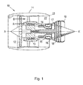
- a ducted fan gas turbine engine incorporating the invention is generally indicated at 10 and has a principal and rotational axis X-X.
- the engine comprises, in axial flow series, an air intake 11, a propulsive fan 12, an intermediate pressure compressor 13, a high-pressure compressor 14, combustion equipment 15, a high-pressure turbine 16, an intermediate pressure turbine 17, a low-pressure turbine 18 and a core engine exhaust nozzle 19.
- a nacelle 21 generally surrounds the engine 10 and defines the intake 11, a bypass duct 22 and a bypass exhaust nozzle 23.
- air entering the intake 11 is accelerated by the fan 12 to produce two air flows: a first air flow A into the intermediate pressure compressor 13 and a second air flow B which passes through the bypass duct 22 to provide propulsive thrust.
- the intermediate pressure compressor 13 compresses the air flow A directed into it before delivering that air to the high pressure compressor 14 where further compression takes place.
- the compressed air exhausted from the high-pressure compressor 14 is directed into the combustion equipment 15 where it is mixed with fuel and the mixture combusted.
- the resultant hot combustion products then expand through, and thereby drive the high, intermediate and low-pressure turbines 16, 17, 18 before being exhausted through the nozzle 19 to provide additional propulsive thrust.
- the high, intermediate and low-pressure turbines respectively drive the high and intermediate pressure compressors 14, 13 and the fan 12 by suitable interconnecting shafts.
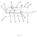
- Figure 2 shows an example of a bearing cage 30, according to an aspect of the present invention, incorporated into a gas turbine jet engine.
- Fig. 2 is a cross-section of a portion of such a gas turbine engine, and shows (only) the upper portion of a rotatable shaft 32 and (only) the upper portion of a (e.g. fixed) ring 34 arranged coaxially with the shaft 32.
- a (e.g. fixed) ring 34 arranged coaxially with the shaft 32.
- Only the upper portion of the bearing cage 30 is shown.
- the principal axis of rotation of the bearing cage 30 is coaxially aligned with the axis of rotation of rotatable shaft 32.
- the principal axis of rotation of the bearing cage is the axis about which the bearing cage rotates in use.
- the bearing cage 30 defines a bore in which the shaft 32 is located and rotatable.
- the ring 34 defines another bore in which the bearing cage 30 is located and rotatable.
- the axis of each bore is preferably coaxially aligned with the principal axis of rotation of the bearing cage 30.
- the bearing 30 includes a main cage body 31, located in a central region of the bearing cage 30, in the axial direction.
- a series of pockets 36 are arranged circumferentially around the main cage body 31.
- Each pocket 36 houses a rolling element 38, which is rotatable within the pocket 36.
- Rolling elements 38 may be spherical, e.g. ball bearings, or cylindrical, e.g. rollers. In the example shown, the rolling elements are cylindrical, and have an axis of rotation which is parallel to, but radially offset from, the principal axis of rotation of the bearing cage.
- the rolling bearing elements 38 In addition to rotating about their own axis of rotation, the rolling bearing elements 38 typically rotate about the principal axis of rotation of the bearing cage 30, e.g. as the shaft 32 is rotated.
- Rolling bearing elements 38 engage with the ring 34 and with the shaft 32, to bear the load between them, e.g. via bearing working contacts 40.
- Bearing working contacts 40 require lubrication, e.g. by lubricant delivered by oil holes 42. The lubricant can be degraded by overheating and/or by the introduction of debris or contaminants.
- cage wings 41 are provided.
- Cage wings 41 typically project from the main cage body 31 in the axial direction (i.e. in the direction of the principal axis of rotation of the bearing cage).
- Cage wings 41 typically extend circumferentially entirely around the principal axis of rotation of the bearing cage, e.g. to form a cylinder.
- the cage wings 41 typically provide an axial extension to the bore of the bearing cage.
- a cage wing 41 may be provided with a weir to help encourage scavenged lubricant to flow towards the desired region, typically towards the bearing working contacts.
- An inner piloted bearing cage typically includes such a weir on its inner surface.
- An outer piloted bearing cage may include such a weir on its outer surface.
- the bearing arrangement shown in Figure 2 is housed within a bearing chamber 43.
- the bearing chamber 43 is not typically hermetically sealed from the surrounding environment, in other words it is not typically an airtight chamber.
- a non-airtight seal 44 may be provided between shaft 32 and the bearing chamber 43.
- the principal purpose of seal 44 is not to prevent gas flow in to the bearing chamber, but to prevent lubricant (oil) flow out of the bearing chamber 43.
- seal 44 may be a labyrinth seal, for example.
- Seal 44 permits a flow of gas from outside the bearing chamber to pass through it into the bearing chamber, as shown by arrows A and B in Figure 2 .
- the pressure at A will be sufficiently greater than at B to ensure that oil is prevented from flowing out of the chamber 43 through seal 44.
- a flow of gas from A to B introduces undesirable debris and/or contaminants into the bearing chamber 43.
- the gas flowing from A to B is of a high temperature and typically has a relatively high velocity, and can thus cause problems as discussed.
- the shaft 32 and the seal 44 are typically arranged such that the flow of gas is directed towards the bearing cage 30, and thus the bearing working contacts 40.
- the present invention provides a flow deflector 46 arranged to deflect or re-direct the flow of gas, entering the bearing chamber via the seal, away from the bearing assembly; in particular away from the bearing working contacts.
- Flow detector 46 projects from the cage wing 41 in the radial direction, to intercept the air flow and encourage it to flow radially outwards (away from the bearing) before it can enter the bearing.
- the bearing chamber 43 preferably includes a chamber exit 50.
- the flow deflector 46 re-directs the gas flow towards the chamber exit 50, as represented in Fig. 2 by arrow C.
- the chamber exit 50 is arranged radially outwards of the bearing cage 30, and in particular radially outwards of the flow deflector 46.
- the flow deflector is preferably an additional tang projecting from the cage wing 41 in the radial direction.
- the flow deflector 46 is an additional tang projecting from the outer perimeter (circumference) of the cage wing 41.
- the flow deflector 46 typically projects from the axial tip of the cage wing 41.
- the flow deflector 46 preferably extends around the entire circumference of the cage wing 41.
- the flow deflector 46 may be thought of as a lip or flange arranged circumferentially around the cage wing 41, e.g. at its axial extremity. These arrangements are preferred to minimize the additional mass contributed by the flow deflector 46.
- the flow deflector is located between the source of the gas flow (e.g. the seal in this example) and the bearing assembly, in particular the bearing working contacts 40.
- the flow deflector 46 may therefore be located to block the direct line of sight between the source of the gas flow and the bearing assembly; in particular the bearing working contacts 40.
- the flow deflector may be arranged elsewhere to block the flowpath of the gas flow to prevent it reaching the bearing assembly; in particular the bearing working contacts.
- the flow deflector 46 includes an outwardly facing face 48, suitably shaped to encourage the re-direction, or deflection, of the gas flow radially outwards before reaching the bearing assembly, and in particular the working contacts of the bearing assembly.
- the face 48 may be angled, e.g. to project back towards the main cage body 31, to encourage such a re-direction.
- the extent of projection of the flow deflector 46 in the radial direction may also vary dependent on the same factors.
- a relatively large flow deflector is preferable, so as to block as much as possible of the flowpath between the source of the gas flow and the bearing assembly; in particular the bearing working contacts.
- a simple configuration of a flow detector 46 according to the present invention comprises a planar face 48 formed circumferentially around the cage wing 41 to project in the radial direction therefrom.
- the face may be orthogonal to the principal axis of rotation of the bearing cage. Preferably, however, it is angled back towards the main cage body 31.
- the face 48 may be considered to be chamfered or bevelled.
- this chamfer or bevel would be represented by a straight line which is positioned at an angle between the source of gas flow (e.g. the seal in this example) and the bearing assembly.
- a simple chamfer or bevel may be replaced with compound angles and/or curves, for example to provide a smooth re-direction or deflection of the gas flow. This might be desirable to minimise the risk of turbulent gas flow and the associated heat generation in the bearing chamber, to avoid the aforementioned problems.
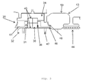
- FIG. 3 A representation of a compound angle and curved cage debris deflector is shown in Fig. 3 .
- the face 48 may be formed of one or more compound angles, such that the face actively re-directs the gas flow away from the bearing assembly (in particular the bearing working contacts 40) not only in the radial direction by also in the axial direction. This may also be achieved by curving the face 48 away from the cage main body, towards the radial extremity of the face 48.
- an intermediate region of the face 48 in the radial direction
- the axial distance from the central region of the bearing cage to the face(s) 48 of the flow deflector(s) 46 is typically selected to ensure that the scavenge route of the lubricant from the bearing is not adversely affected.
- the scavenge route must maintain sufficient area to pass all of the lubricant from the bearing assembly without causing a choke point, or choke region, that would otherwise restrict the flow of lubricant and potentially lead to flooding of the bearing. From a known volume of lubricant supplied to the bearing assembly, the required scavenge area can be calculated by the skilled person using standard fluid dynamics theory.
- the additional material added to the cage wing(s) by virtue of the flow deflector(s) provides additional stiffness to the cage wing(s) which reduces the (undesirable) growth of the wing tip during operation. This effectively helps to maintain the structure of cage wing and hence provides an improved efficiency of oil use in the bearing.
- a flow detector may be provided for each cage wing 41, it is also envisaged that a cage bearing having a pair of cage wings 41 may be provided with only a single flow deflector 46, i.e. projecting from only one of the cage wings 41. This may be due to limitations imposed by the surrounding architecture for example. Such an arrangement may also be preferred where only a single seal is provided in the bearing chamber, and thus only a single flow deflector is considered necessary.
- bore has been used herein, methods other than boring could be used to form the bore, for example, machining other than boring, moulding, casting, etching, laser cutting, etc. could be used to form a bearing cage having an inner surface defining a bore.
- the term lumen could be used in place of bore.
Landscapes
- Engineering & Computer Science (AREA)
- General Engineering & Computer Science (AREA)
- Mechanical Engineering (AREA)
- Rolling Contact Bearings (AREA)
Abstract
a cage body having an inner surface defining a bore coaxially aligned with the principal rotational axis of the bearing cage;
a plurality of pockets, each pocket being suitable for housing a rolling element of the rolling element bearing assembly, the pockets being arranged sequentially around the cage body with respect to the principal rotational axis of the bearing cage; and
a skirt projecting from the cage body in the axial direction;
characterized by
a flow deflector projecting from the skirt in the radial direction.
Description
- The present invention relates to bearing cages providing improved protection for the working contacts of bearings, in particular bearings in gas turbine engines.
- A gas turbine engine includes an engine outer structure, which is essentially a pressure vessel that contains hot, flowing air, and support structures for the rotating elements of the engine, which extend through the pressure vessel in order to support the rotating elements whilst still allowing air to pass from the front to rear of the engine.
- Generally, the support structures are circular when viewed along the axis of the engine, with a number of struts or vanes joining inner and outer rings and a bearing chamber located in the middle. Inside the bearing housings, the bearings allow free rotation, yet precise centring, of the rotating elements of the engine such as drive shafts.
- The bearing chamber provides a favourable environment for the bearings to operate reliably. For example, inside the chamber, nozzles are provided to distribute lubricant to the bearings. To prevent lubricant leaking out of the bearing chamber, and to prevent the ingress to the chamber of excess hot air, the bearing chamber is separated from the surrounding environment by seals. In use, the air pressure in the environment surrounding the bearing chamber is at a higher pressure than inside the chamber, and typically gas flows in to the chamber through the seals. Thus the seals may be provided in the form of labyrinth seals, for example. This inward flow of air prevents oil from migrating in the opposite direction out of the bearing chamber through the seal.
- However, this arrangement can be disadvantageous. For example, the inward flow of gas may bring with it unwanted detritus, debris and/or other undesirable contaminants, which could adversely affect the operation of the bearings.
- Furthermore, the incoming gas may be of a sufficiently high temperature to create an axial thermal gradient across the bearing. This may cause the bearing cage to warp, e.g. to cone, and may result in dynamic cage instability of the bearing.
- It may also cause a temperature rise in the lubricant (oil) in the bearing, potentially leading to degradation of the lubricant and thus to bearing damage. Indeed, lubricant is typically scavenged from the bearing and reused elsewhere in the engine, thus degraded lubricant could have adverse effects elsewhere in the engine.
- The architecture of the engine will often dictate when a bearing and a seal are in axial alignment, or are close to axial alignment. In such an alignment, the typical route of the gas flow from the seal is against the direction of lubricant flowing from the bearing, and this impact of lubricant (in particular, oil) and gas (in particular, air) may cause local disruption to the oil/air flow and increase the temperature of the oil in the bearing chamber, leading to similar disadvantages as those described above.
- The present invention has been devised in view of at least these problems/disadvantages.
- Therefore, the present invention provides a bearing assembly according to the appended claims.
- A bearing cage for the bearing assembly includes: a cage body having an inner surface defining a bore having an axis arranged coaxially with the principal rotational axis of the bearing cage; a plurality of pockets, each pocket being suitable for housing a rolling element of the rolling element bearing assembly, the pockets being arranged sequentially around the cage body with respect to the principal rotational axis of the bearing cage; a skirt projecting from the cage body in the axial direction; and a flow deflector projecting from the skirt in the radial direction.
- Thus, when installed in a rolling element bearing assembly the flow deflector can prevent debris or undesirably hot gases present in the surrounding environment from entering the assembly.
- Preferably, the flow deflector extends circumferentially entirely around the skirt.
- Respective skirts may be provided to project from the cage body in opposite axial directions, a respective flow deflector projecting from each skirt in the radial direction. Thus, the assembly can be protected from debris in both axial directions.
- The or each flow deflector preferably projects outwardly from the principal rotational axis of the bearing cage in the radial direction. This arrangement is of particular benefit when the bearing cage is an inner piloted bearing cage. Thus, the inner surface of the bearing cage defining the bore may provide the pilot surface of the bearing cage.
- However, the or each flow deflector may project inwardly towards the axis of the bore in the radial direction, for example when the bearing cage is an outer piloted bearing cage. This arrangement is of particular benefit when the bearing cage is an outer piloted bearing cage. Thus, the outer surface of the bearing cage defining the bore may provide the pilot surface of the bearing cage.
- The or each flow deflector preferably includes an outwardly facing deflector face, the deflector face being shaped, along its length (extent) of projection in the radial direction, to extend in the axial direction towards the cage body. Thus, the deflector face may be angled towards the cage body. Shaping the deflector face is beneficial in order to reduce the turbulence in the gas flow.
- The deflector face, along its length (extent) of projection in the radial direction, may be formed to include a compound angle, or a plurality of compound angles.
- The deflector face may be curved along at least a portion its length (extent) of projection in the radial direction, e.g. to provide a smooth deflection, or re-direction, of the gas.
- The deflector face may be curved along its length (extent) of projection, in the radial direction, such that the closest region of the deflector face to the cage body is formed in an intermediate region along the length (extent) of projection of the deflector face. Thus, the deflector face may, in addition to deflecting (or re-directing) the gas radially away from the bearing cage, deflect (or re-direct) the gas axially away from the bearing cage.
- Preferably, each respective skirt extends circumferentially entirely around the principal rotational axis of the bearing cage. Preferably, each flow deflector extends circumferentially entirely around a respective skirt.
- Any of the features of this first aspect of the invention may be incorporated into any of the other aspects described herein; in particular, into the following aspect(s).
- The present invention provides a bearing arrangement including: a rolling element bearing assembly including a bearing cage having a cage body having an inner surface defining a bore coaxially aligned with the principal rotational axis of the bearing cage, a plurality of pockets, each pocket housing a rotatable rolling element of the rolling element bearing assembly, the pockets being arranged sequentially around the cage body with respect to the principal rotational axis of the bearing cage, and a skirt projecting from the cage body in the axial direction; a first body located in the bore of the bearing cage and coaxially aligned with the principal rotational axis of the bearing cage, and arranged to engage each of the rolling elements; a second body arranged circumferentially around the bearing cage to engage the rolling elements, the first and second bodies being rotatable with respect to one another about the principal rotational axis of the bearing cage; and a bearing chamber arranged to house the rolling element bearing assembly, the bearing chamber providing a source of gas flow into the bearing chamber; characterized in that the bearing cage includes a flow deflector projecting from the skirt in the radial direction, for deflecting the gas flow away from the cage body.
- Thus, the present invention provides a bearing arrangement in which a gas flow, potentially containing debris or other undesirable contaminants, is deflected away from a rolling element bearing assembly so as to prevent undesirably hot gases, debris and/or other contaminants from entering the bearing assembly.
- In other words, the flow deflectors re-direct the gas flow from the source of the gas flow (e.g. the seal adjacent the bearing assembly) which results in a reduction in risk of debris entering the working contacts of the bearing. This therefore reduces the risk of the bearing suffering premature damage and failure. Consequently, the robustness of the bearing to its operational environment will be improved, leading to an improvement in reliability.
- The or each flow deflector preferably projects outwardly from the principal rotational axis of the bearing cage in the radial direction. This arrangement is of particular benefit when the bearing cage is an inner piloted bearing cage. Thus, the inner surface of the bearing cage defining the bore may provide a pilot surface for engagement with the first body.
- Preferably, the flow deflector intercepts the gas flow between the source and the cage body.
- Preferably, the flow deflector is arranged to block the direct line of sight between the source and the cage body.
- The source of gas flow is preferably a seal, e.g. provided to seal the bearing chamber; for example, to prevent the outflow of gases or fluids from the bearing chamber. Preferably, the seal is located adjacent the bearing cage, e.g. in the direction of the axis of the bore and/or the direction of the principal axis of rotation of the bearing cage. The seal is preferably configured to permit gas to flow into the bearing chamber when the gas pressure on the external side of the seal exceeds the gas pressure inside the bearing chamber by a predetermined amount.
- Thus, the present invention may provide a bearing arrangement including: a rolling element bearing assembly including a bearing cage having a cage body having an inner surface defining a bore coaxially aligned with the principal rotational axis of the bearing cage, a plurality of pockets, each pocket housing a rotatable rolling element of the rolling element bearing assembly, the pockets being arranged sequentially around the cage body with respect to the principal rotational axis of the bearing cage, and a skirt projecting from the cage body in the axial direction; a first body located in the bore of the bearing cage and coaxially aligned with the principal rotational axis of the bearing cage, and arranged to engage each of the rolling elements; a second body arranged circumferentially around the bearing cage to engage the rolling elements, the first and second bodies being rotatable with respect to one another about the principal rotational axis of the bearing cage; and a bearing chamber arranged to house the rolling element bearing assembly, the bearing chamber providing a seal configured to permit gas to flow into the chamber when the gas pressure on the external side of the seal exceeds the gas pressure inside the bearing chamber by a predetermined amount, wherein the seal is located adjacent the bearing cage in the axial direction (e.g. of the axis of the bore and/or of the principal rotational axis of the bearing cage); characterized in that the bearing cage includes a flow deflector projecting from the skirt in the radial direction, for deflecting the gas flow away from the cage body.
- Preferably, the flow deflector intercepts the gas flow between the seal and the cage body. In other words, the flow deflector preferably lies on the flowpath of the incoming gas flow, between the seal and the bearing cage.
- The flow deflector may be arranged to block the direct line of sight between the seal and the cage body.
- The bearing chamber typically includes a chamber exit, and thus the flow deflector is preferably arranged to deflect the gas flow towards the chamber exit.
- The chamber exit is preferably located radially outwards with respect to the flow deflector, e.g with respect to the principal axis of rotation of the bearing cage.
- In a further aspect, the present invention provides a method of assembling a gas turbine engine including the step of incorporating a bearing cage or a bearing arrangement according to the teaching and disclosure herein into the gas turbine engine.
- In yet another aspect the present invention provides a gas turbine engine including a bearing cage, or a bearing arrangement, according to the teaching and disclosure herein.
- According to the present invention, the redirection of gas flow reduces the interaction between the gas flow from the seal and the flow of lubricant scavenged from the bearing. This improves the overall lubricant scavenge capability of the bearing, reducing the turbulence in the chamber and leading to a reduction in heat transfer to the lubricant in the chamber, meaning that the performance of the bearing is maintained at acceptable levels for longer periods.
- Indeed, the redirection of gas flow at the extremities of the bearing cage wing can reduce the heat transferred to the bearing from the gas to the side of the cage, e.g. above the pilot surface (particularly, but not exclusively, in an inner piloted arrangement as shown in the figures). This reduces the increase in axial thermal gradient across the bearing typically suffered by prior art bearing cages, and thus reduces the risk of bearing cage coning which can cause dynamic cage instabilities.
- Embodiments of the invention will now be described by way of example with reference to the accompanying drawings in which:
-
Figure 1 shows an example of a ducted fan gas turbine engine incorporating the present invention; -
Figure 2 shows an example of a bearing cage and bearing arrangement according to the present invention; -
Figure 3 shows an example of another bearing cage and bearing arrangement according to the present invention. - With reference to
Figure 1 , a ducted fan gas turbine engine incorporating the invention is generally indicated at 10 and has a principal and rotational axis X-X. The engine comprises, in axial flow series, an air intake 11, apropulsive fan 12, anintermediate pressure compressor 13, a high-pressure compressor 14,combustion equipment 15, a high-pressure turbine 16, anintermediate pressure turbine 17, a low-pressure turbine 18 and a coreengine exhaust nozzle 19. Anacelle 21 generally surrounds theengine 10 and defines the intake 11, abypass duct 22 and abypass exhaust nozzle 23. - During operation, air entering the intake 11 is accelerated by the
fan 12 to produce two air flows: a first air flow A into theintermediate pressure compressor 13 and a second air flow B which passes through thebypass duct 22 to provide propulsive thrust. Theintermediate pressure compressor 13 compresses the air flow A directed into it before delivering that air to thehigh pressure compressor 14 where further compression takes place. - The compressed air exhausted from the high-
pressure compressor 14 is directed into thecombustion equipment 15 where it is mixed with fuel and the mixture combusted. The resultant hot combustion products then expand through, and thereby drive the high, intermediate and low-pressure turbines nozzle 19 to provide additional propulsive thrust. The high, intermediate and low-pressure turbines respectively drive the high andintermediate pressure compressors fan 12 by suitable interconnecting shafts. -
Figure 2 shows an example of a bearingcage 30, according to an aspect of the present invention, incorporated into a gas turbine jet engine.Fig. 2 is a cross-section of a portion of such a gas turbine engine, and shows (only) the upper portion of arotatable shaft 32 and (only) the upper portion of a (e.g. fixed)ring 34 arranged coaxially with theshaft 32. Likewise, only the upper portion of the bearingcage 30 is shown. - The principal axis of rotation of the bearing
cage 30 is coaxially aligned with the axis of rotation ofrotatable shaft 32. The principal axis of rotation of the bearing cage is the axis about which the bearing cage rotates in use. - The bearing
cage 30 defines a bore in which theshaft 32 is located and rotatable. Thering 34 defines another bore in which the bearingcage 30 is located and rotatable. The axis of each bore is preferably coaxially aligned with the principal axis of rotation of the bearingcage 30. - The
bearing 30 includes amain cage body 31, located in a central region of the bearingcage 30, in the axial direction. - A series of
pockets 36 are arranged circumferentially around themain cage body 31. Eachpocket 36 houses a rollingelement 38, which is rotatable within thepocket 36.Rolling elements 38 may be spherical, e.g. ball bearings, or cylindrical, e.g. rollers. In the example shown, the rolling elements are cylindrical, and have an axis of rotation which is parallel to, but radially offset from, the principal axis of rotation of the bearing cage. - In addition to rotating about their own axis of rotation, the rolling
bearing elements 38 typically rotate about the principal axis of rotation of the bearingcage 30, e.g. as theshaft 32 is rotated. -
Rolling bearing elements 38 engage with thering 34 and with theshaft 32, to bear the load between them, e.g. via bearing workingcontacts 40. Bearing workingcontacts 40 require lubrication, e.g. by lubricant delivered by oil holes 42. The lubricant can be degraded by overheating and/or by the introduction of debris or contaminants. - To help ensure that lubricant is scavenged efficiently from
oil holes 42,cage wings 41 are provided.Cage wings 41 typically project from themain cage body 31 in the axial direction (i.e. in the direction of the principal axis of rotation of the bearing cage).Cage wings 41 typically extend circumferentially entirely around the principal axis of rotation of the bearing cage, e.g. to form a cylinder. Thecage wings 41 typically provide an axial extension to the bore of the bearing cage. - A cage wing 41 (or skirt) may be provided with a weir to help encourage scavenged lubricant to flow towards the desired region, typically towards the bearing working contacts. An inner piloted bearing cage typically includes such a weir on its inner surface. An outer piloted bearing cage may include such a weir on its outer surface.
- Typically, the bearing arrangement shown in
Figure 2 is housed within a bearingchamber 43. The bearingchamber 43 is not typically hermetically sealed from the surrounding environment, in other words it is not typically an airtight chamber. - For example, a
non-airtight seal 44 may be provided betweenshaft 32 and the bearingchamber 43. The principal purpose ofseal 44 is not to prevent gas flow in to the bearing chamber, but to prevent lubricant (oil) flow out of the bearingchamber 43. Thus, seal 44 may be a labyrinth seal, for example. -
Seal 44 permits a flow of gas from outside the bearing chamber to pass through it into the bearing chamber, as shown by arrows A and B inFigure 2 . In use the pressure at A will be sufficiently greater than at B to ensure that oil is prevented from flowing out of thechamber 43 throughseal 44. - However, a flow of gas from A to B introduces undesirable debris and/or contaminants into the bearing
chamber 43. Furthermore, the gas flowing from A to B is of a high temperature and typically has a relatively high velocity, and can thus cause problems as discussed. - Indeed, due to the architecture of the bearing arrangement, the
shaft 32 and theseal 44 are typically arranged such that the flow of gas is directed towards the bearingcage 30, and thus thebearing working contacts 40. - Thus, the present invention provides a
flow deflector 46 arranged to deflect or re-direct the flow of gas, entering the bearing chamber via the seal, away from the bearing assembly; in particular away from the bearing working contacts. -
Flow detector 46 projects from thecage wing 41 in the radial direction, to intercept the air flow and encourage it to flow radially outwards (away from the bearing) before it can enter the bearing. - The bearing
chamber 43 preferably includes achamber exit 50. Preferably, theflow deflector 46 re-directs the gas flow towards thechamber exit 50, as represented inFig. 2 by arrow C. Preferably, therefore, thechamber exit 50 is arranged radially outwards of the bearingcage 30, and in particular radially outwards of theflow deflector 46. - The flow deflector is preferably an additional tang projecting from the
cage wing 41 in the radial direction. Typically, theflow deflector 46 is an additional tang projecting from the outer perimeter (circumference) of thecage wing 41. Theflow deflector 46 typically projects from the axial tip of thecage wing 41. Theflow deflector 46 preferably extends around the entire circumference of thecage wing 41. Thus, in structural terms, theflow deflector 46 may be thought of as a lip or flange arranged circumferentially around thecage wing 41, e.g. at its axial extremity. These arrangements are preferred to minimize the additional mass contributed by theflow deflector 46. - Preferably, the flow deflector is located between the source of the gas flow (e.g. the seal in this example) and the bearing assembly, in particular the
bearing working contacts 40. In some embodiments, where the gas flow is linear, theflow deflector 46 may therefore be located to block the direct line of sight between the source of the gas flow and the bearing assembly; in particular thebearing working contacts 40. However, where the gas flow is not linear, the flow deflector may be arranged elsewhere to block the flowpath of the gas flow to prevent it reaching the bearing assembly; in particular the bearing working contacts. - The
flow deflector 46 includes an outwardly facingface 48, suitably shaped to encourage the re-direction, or deflection, of the gas flow radially outwards before reaching the bearing assembly, and in particular the working contacts of the bearing assembly. For example, theface 48 may be angled, e.g. to project back towards themain cage body 31, to encourage such a re-direction. - The angle of
face 48 with respect to the principal axis of rotation of the bearingcage 30 may vary dependent on the relative location of the gas flow source (e.g. the seal in this example) with respect to the bearing assembly (in particular with respect to the bearing working contacts 40) and/or the chamber exit. Likewise, the angle may vary depending on the pressure of the gas flow. - The extent of projection of the
flow deflector 46 in the radial direction may also vary dependent on the same factors. - If the surrounding architecture permits, then a relatively large flow deflector is preferable, so as to block as much as possible of the flowpath between the source of the gas flow and the bearing assembly; in particular the bearing working contacts.
- A simple configuration of a
flow detector 46 according to the present invention comprises aplanar face 48 formed circumferentially around thecage wing 41 to project in the radial direction therefrom. The face may be orthogonal to the principal axis of rotation of the bearing cage. Preferably, however, it is angled back towards themain cage body 31. Theface 48 may be considered to be chamfered or bevelled. - In a cross-section taken parallel to the principal axis of rotation of the bearing
cage 30, this chamfer or bevel would be represented by a straight line which is positioned at an angle between the source of gas flow (e.g. the seal in this example) and the bearing assembly. - However, a simple chamfer or bevel may be replaced with compound angles and/or curves, for example to provide a smooth re-direction or deflection of the gas flow. This might be desirable to minimise the risk of turbulent gas flow and the associated heat generation in the bearing chamber, to avoid the aforementioned problems.
- A representation of a compound angle and curved cage debris deflector is shown in
Fig. 3 . - The
face 48 may be formed of one or more compound angles, such that the face actively re-directs the gas flow away from the bearing assembly (in particular the bearing working contacts 40) not only in the radial direction by also in the axial direction. This may also be achieved by curving theface 48 away from the cage main body, towards the radial extremity of theface 48. Thus, an intermediate region of the face 48 (in the radial direction) may define an annulus which is closer to the cagemain body 31, in the axial direction, than radially inner and outer regions of theface 48. - The axial distance from the central region of the bearing cage to the face(s) 48 of the flow deflector(s) 46 is typically selected to ensure that the scavenge route of the lubricant from the bearing is not adversely affected. The scavenge route must maintain sufficient area to pass all of the lubricant from the bearing assembly without causing a choke point, or choke region, that would otherwise restrict the flow of lubricant and potentially lead to flooding of the bearing. From a known volume of lubricant supplied to the bearing assembly, the required scavenge area can be calculated by the skilled person using standard fluid dynamics theory.
- Only a single cage wing, rather than a pair as shown in
Figs. 2 and3 , may be provided in certain arrangements. This may be due to limitations imposed by the surrounding architecture for example. Thus, only asingle flow deflector 46 may be provided. Such an arrangement may also be preferred where only a single seal is provided in the bearing chamber, and thus only a single flow deflector is considered necessary. - The additional material added to the cage wing(s) by virtue of the flow deflector(s) provides additional stiffness to the cage wing(s) which reduces the (undesirable) growth of the wing tip during operation. This effectively helps to maintain the structure of cage wing and hence provides an improved efficiency of oil use in the bearing.
- Although a flow detector may be provided for each
cage wing 41, it is also envisaged that a cage bearing having a pair ofcage wings 41 may be provided with only asingle flow deflector 46, i.e. projecting from only one of thecage wings 41. This may be due to limitations imposed by the surrounding architecture for example. Such an arrangement may also be preferred where only a single seal is provided in the bearing chamber, and thus only a single flow deflector is considered necessary. - It is to be understood that although the flow deflector is said to project from the skirt in the radial direction, it is not intended that the invention be interpreted to be limited to flow deflectors which only extend radially, i.e. which extend parallel to the radii. Rather, it is to be understood that the flow deflectors project from the skirt such that they extend away from, or towards, the axis of the skirt (and therefore the bore), even though they may extend at an angle to the axis.
- It is also to be understood that, although the term bore has been used herein, methods other than boring could be used to form the bore, for example, machining other than boring, moulding, casting, etching, laser cutting, etc. could be used to form a bearing cage having an inner surface defining a bore. The term lumen could be used in place of bore.
- When used in this specification and claims, the terms "comprises" and "comprising" and variations thereof mean that the specified features, steps or integers are included. The terms are not to be interpreted to exclude the presence of other features, steps or integers.
- The features disclosed in the foregoing description, or in the following claims, or in the accompanying drawings, expressed in their specific forms or in terms of a means for performing the disclosed function, or a method or process for obtaining the disclosed results, as appropriate, may, separately, or in any combination of such features, be utilised for realising the invention in diverse forms thereof.
- While the invention has been described in conjunction with the exemplary embodiments described above, many equivalent modifications and variations will be apparent to those skilled in the art when given this disclosure. Accordingly, the exemplary embodiments of the invention set forth above are considered to be illustrative and not limiting. Various changes to the described embodiments may be made without departing from the spirit and scope of the invention.
Claims (15)
- A bearing arrangement including:a rolling element bearing assembly including a bearing cage (30) having
a cage body (31) having an inner surface defining a bore coaxially aligned with the principal rotational axis of the bearing cage,
a plurality of pockets (36), each pocket housing a rotatable rolling element (38) of the rolling element bearing assembly, the pockets being arranged sequentially around the cage body with respect to the principal rotational axis of the bearing cage, and
a skirt (41) projecting from the cage body in the axial direction;a first body (32) located in the bore of the bearing cage and coaxially aligned with the principal rotational axis of the bearing cage, and arranged to engage each of the rolling elements;a second body arranged circumferentially around the bearing cage to engage the rolling elements, the first and second bodies being rotatable with respect to one another about the principal rotational axis of the bearing cage; anda bearing chamber (43) arranged to house the rolling element bearing assembly, the bearing chamber providing a source of gas flow into the bearing chamber;characterised in that:the bearing cage includes a flow deflector (46) projecting from the skirt in the radial direction which is arranged to intercept the gas flow (B) between the source and the cage body so as to deflect the gas flow away from the cage body. - A bearing arrangement according to claim 1, wherein the flow deflector is arranged to block the direct line of sight between the source and the cage body.
- A bearing arrangement according to any one of claims 1 and 2, wherein the source of gas flow is a seal (44) provided to seal the bearing chamber.
- A bearing arrangement according to any preceding claim, wherein respective skirts are provided to project from the cage body in opposite axial directions, a respective flow deflector projecting from each skirt in the radial direction.
- A bearing arrangement according to any preceding claim, wherein the or each flow deflector projects radially outwardly from the principal rotational axis of the bearing cage.
- A bearing arrangement according to any preceding claim, wherein the or each flow deflector includes an outwardly facing deflector face (48), the deflector face being shaped, along its extent of projection in the radial direction, to extend in the axial direction towards the cage body.
- A bearing arrangement according to any preceding claim, wherein the deflector face, along its extent of projection in the radial direction, is formed to include one or more compound angles.
- A bearing arrangement according to any preceding claim, wherein the deflector face is curved along at least a portion of its extent of projection in the radial direction.
- A bearing arrangement according to any preceding claim, wherein the deflector face is curved along at least a portion of its extent of projection in the radial direction, such that the closest region of the deflector face to the cage body is formed in an intermediate region along the extent of projection in the radial direction of the deflector face.
- A bearing arrangement according to any preceding claim, wherein the or each skirt extends circumferentially entirely around the principal rotational axis of the bearing cage.
- A bearing arrangement according to any preceding claim, wherein each flow deflector extends circumferentially entirely around a respective skirt.
- A bearing arrangement according to any of claims 3 to 11, wherein the seal is located adjacent the bearing cage in the axial direction.
- A bearing arrangement according to claim 12, wherein the seal is configured to permit gas to flow into the bearing chamber when the gas pressure on the external side of the seal exceeds the gas pressure inside the bearing chamber by a predetermined amount.
- A bearing arrangement according to any preceding claim, wherein the bearing chamber includes a chamber exit (50), and the flow deflector is arranged to deflect the gas flow towards the chamber exit.
- A bearing arrangement according to any preceding claim wherein the chamber exit is located radially outwards of the flow deflector with respect to the principal axis of rotation of the bearing cage.
Applications Claiming Priority (1)
| Application Number | Priority Date | Filing Date | Title |
|---|---|---|---|
| GBGB1314049.6A GB201314049D0 (en) | 2013-08-06 | 2013-08-06 | Bearing cage deflector |
Publications (3)
| Publication Number | Publication Date |
|---|---|
| EP2835544A2 true EP2835544A2 (en) | 2015-02-11 |
| EP2835544A3 EP2835544A3 (en) | 2015-04-15 |
| EP2835544B1 EP2835544B1 (en) | 2018-01-17 |
Family
ID=49224226
Family Applications (1)
| Application Number | Title | Priority Date | Filing Date |
|---|---|---|---|
| EP14176993.5A Active EP2835544B1 (en) | 2013-08-06 | 2014-07-15 | Bearing cage deflector |
Country Status (3)
| Country | Link |
|---|---|
| US (1) | US9194429B2 (en) |
| EP (1) | EP2835544B1 (en) |
| GB (1) | GB201314049D0 (en) |
Cited By (2)
| Publication number | Priority date | Publication date | Assignee | Title |
|---|---|---|---|---|
| US9951814B2 (en) | 2015-11-11 | 2018-04-24 | Rolls-Royce Plc | Bearing arrangement and a bearing cage |
| US20250079938A1 (en) * | 2023-08-28 | 2025-03-06 | Allison Transmission, Inc. | Motor air gap oil flow management |
Families Citing this family (3)
| Publication number | Priority date | Publication date | Assignee | Title |
|---|---|---|---|---|
| ES2795291T3 (en) | 2013-02-13 | 2020-11-23 | Procter & Gamble | Anise flavored medicine |
| US10451113B2 (en) * | 2017-05-18 | 2019-10-22 | General Electric Company | Bearing cages for roller bearing assemblies |
| DE102019205345A1 (en) * | 2019-04-12 | 2020-10-15 | Rolls-Royce Deutschland Ltd & Co Kg | Rolling element device with jointly tiltable raceways |
Family Cites Families (19)
| Publication number | Priority date | Publication date | Assignee | Title |
|---|---|---|---|---|
| GB144259A (en) * | 1919-05-31 | 1921-04-21 | Sanford Alexander Moss | Improvements in and relating to turbo-superchargers for aeroplanes, airships and the like |
| US2838348A (en) * | 1956-04-17 | 1958-06-10 | Gen Electric | High speed anti-friction bearings |
| GB936213A (en) * | 1961-05-03 | 1963-09-04 | Rolls Royce | Bearing assembly |
| GB931581A (en) * | 1962-02-12 | 1963-07-17 | Rolls Royce | Bearing |
| GB961522A (en) * | 1963-01-09 | 1964-06-24 | Rolls Royce | Bearing assembly |
| GB2063383B (en) * | 1979-11-17 | 1983-06-29 | Rolls Royce | Rolling contact bearings |
| GB2073828B (en) * | 1980-04-08 | 1983-09-14 | Rolls Royce | Bearings |
| FR2548297B3 (en) * | 1983-06-28 | 1986-04-18 | Roulements Soc Nouvelle | ROLL RETAINER CAGE FOR BEARINGS |
| DE3532456A1 (en) * | 1985-09-11 | 1987-03-19 | Mtu Muenchen Gmbh | INTERMEDIATE SHAFT (INTERSHAFT) BEARING WITH SQUEEZE FILM DAMPING WITH OR WITHOUT SQUIRREL CAGE |
| DE4424640A1 (en) | 1994-07-13 | 1996-01-18 | Abb Management Ag | Storage of an exhaust gas turbocharger |
| GB2358678B (en) * | 2000-01-25 | 2004-04-28 | Rolls Royce Plc | Bearing damper |
| FR2882116B1 (en) | 2005-02-11 | 2007-04-27 | Snr Roulements Sa | BEARING BEARING COMPRISING A FILTRATION CAGE |
| US20060193545A1 (en) * | 2005-02-25 | 2006-08-31 | Honeywell International Inc. | Rolling element bearing cage with improved pilot surface lubrication |
| FR2929358B1 (en) * | 2008-03-25 | 2010-08-13 | Snecma | TREE GUIDE BEARING IN A TURBOMACHINE |
| GB0821324D0 (en) * | 2008-11-24 | 2008-12-31 | Rolls Royce Plc | A rolling-element bearing |
| DE102010047927A1 (en) * | 2010-10-08 | 2011-04-21 | Schaeffler Technologies Gmbh & Co. Kg | Anti-friction bearing i.e. wheel bearing, for passenger car, has baffle plate arranged adjacent to rolling body path of inner ring or outer ring, where plate extends in radial direction with respect to rotation axis of bearing |
| GB201101226D0 (en) * | 2011-01-25 | 2011-03-09 | Rolls Royce Plc | A bearing race for a rolling-element bearing |
| US8529135B2 (en) * | 2011-08-25 | 2013-09-10 | United Technologies Corporation | Angular contact ball bearing |
| US8727632B2 (en) | 2011-11-01 | 2014-05-20 | General Electric Company | Bearing support apparatus for a gas turbine engine |
-
2013
- 2013-08-06 GB GBGB1314049.6A patent/GB201314049D0/en not_active Ceased
-
2014
- 2014-07-15 EP EP14176993.5A patent/EP2835544B1/en active Active
- 2014-07-16 US US14/332,639 patent/US9194429B2/en active Active
Cited By (2)
| Publication number | Priority date | Publication date | Assignee | Title |
|---|---|---|---|---|
| US9951814B2 (en) | 2015-11-11 | 2018-04-24 | Rolls-Royce Plc | Bearing arrangement and a bearing cage |
| US20250079938A1 (en) * | 2023-08-28 | 2025-03-06 | Allison Transmission, Inc. | Motor air gap oil flow management |
Also Published As
| Publication number | Publication date |
|---|---|
| US20150043861A1 (en) | 2015-02-12 |
| EP2835544B1 (en) | 2018-01-17 |
| EP2835544A3 (en) | 2015-04-15 |
| GB201314049D0 (en) | 2013-09-18 |
| US9194429B2 (en) | 2015-11-24 |
Similar Documents
| Publication | Publication Date | Title |
|---|---|---|
| JP5256524B2 (en) | Hydrodynamic seal with circumferentially varying lift | |
| EP2835544B1 (en) | Bearing cage deflector | |
| RU2687474C2 (en) | Gas turbine engine compressor comprising blades with variable installation angle | |
| JP4005020B2 (en) | Sealing method and apparatus for gas turbine shaft | |
| US20110129342A1 (en) | Turbine assemblies with impingement cooling | |
| EP2835545B1 (en) | Bearing cage with oil circulation means | |
| EP3705689B1 (en) | Method to seal damper cavity of multi-film oil damper | |
| EP3252280B1 (en) | Circumferential plenum for oil damper | |
| CN104154042B (en) | For the extract system of axial flow turbo-machine | |
| US20200088059A1 (en) | Anti-coning aspirating face seal | |
| EP3715651A1 (en) | Bearing housing | |
| EP3312402A1 (en) | Impeller back surface cooling structure and supercharger | |
| US20160258310A1 (en) | Seal arrangement | |
| EP3693541B1 (en) | Gas turbine rotor disk having scallop shield feature | |
| EP3628881B1 (en) | Inner ring for a bearing and method for proportioning lubricant to a bearing | |
| US11293295B2 (en) | Labyrinth seal with angled fins | |
| US10767511B2 (en) | Anti-cavitation device for oil dampers | |
| EP3460184B1 (en) | Seal for a gas turbine | |
| CN102373967B (en) | Turbo Machine | |
| CN108952969B (en) | Bearing Housings for Roller Bearing Assemblies | |
| EP3284917B1 (en) | Active clearance control collector to manifold insert | |
| US10648510B1 (en) | Baffle for installation inside a bearing chamber of a gas turbine engine |
Legal Events
| Date | Code | Title | Description |
|---|---|---|---|
| PUAI | Public reference made under article 153(3) epc to a published international application that has entered the european phase |
Free format text: ORIGINAL CODE: 0009012 |
|
| 17P | Request for examination filed |
Effective date: 20140715 |
|
| AK | Designated contracting states |
Kind code of ref document: A2 Designated state(s): AL AT BE BG CH CY CZ DE DK EE ES FI FR GB GR HR HU IE IS IT LI LT LU LV MC MK MT NL NO PL PT RO RS SE SI SK SM TR |
|
| AX | Request for extension of the european patent |
Extension state: BA ME |
|
| PUAL | Search report despatched |
Free format text: ORIGINAL CODE: 0009013 |
|
| AK | Designated contracting states |
Kind code of ref document: A3 Designated state(s): AL AT BE BG CH CY CZ DE DK EE ES FI FR GB GR HR HU IE IS IT LI LT LU LV MC MK MT NL NO PL PT RO RS SE SI SK SM TR |
|
| AX | Request for extension of the european patent |
Extension state: BA ME |
|
| RIC1 | Information provided on ipc code assigned before grant |
Ipc: F16C 33/38 20060101AFI20150311BHEP Ipc: F01D 25/00 20060101ALI20150311BHEP Ipc: F16C 33/78 20060101ALI20150311BHEP |
|
| RAP1 | Party data changed (applicant data changed or rights of an application transferred) |
Owner name: ROLLS-ROYCE PLC |
|
| R17P | Request for examination filed (corrected) |
Effective date: 20150703 |
|
| RBV | Designated contracting states (corrected) |
Designated state(s): AL AT BE BG CH CY CZ DE DK EE ES FI FR GB GR HR HU IE IS IT LI LT LU LV MC MK MT NL NO PL PT RO RS SE SI SK SM TR |
|
| GRAP | Despatch of communication of intention to grant a patent |
Free format text: ORIGINAL CODE: EPIDOSNIGR1 |
|
| STAA | Information on the status of an ep patent application or granted ep patent |
Free format text: STATUS: GRANT OF PATENT IS INTENDED |
|
| GRAS | Grant fee paid |
Free format text: ORIGINAL CODE: EPIDOSNIGR3 |
|
| INTG | Intention to grant announced |
Effective date: 20171115 |
|
| GRAA | (expected) grant |
Free format text: ORIGINAL CODE: 0009210 |
|
| STAA | Information on the status of an ep patent application or granted ep patent |
Free format text: STATUS: THE PATENT HAS BEEN GRANTED |
|
| AK | Designated contracting states |
Kind code of ref document: B1 Designated state(s): AL AT BE BG CH CY CZ DE DK EE ES FI FR GB GR HR HU IE IS IT LI LT LU LV MC MK MT NL NO PL PT RO RS SE SI SK SM TR |
|
| REG | Reference to a national code |
Ref country code: GB Ref legal event code: FG4D |
|
| REG | Reference to a national code |
Ref country code: CH Ref legal event code: EP |
|
| REG | Reference to a national code |
Ref country code: IE Ref legal event code: FG4D |
|
| REG | Reference to a national code |
Ref country code: AT Ref legal event code: REF Ref document number: 964636 Country of ref document: AT Kind code of ref document: T Effective date: 20180215 |
|
| REG | Reference to a national code |
Ref country code: DE Ref legal event code: R096 Ref document number: 602014019990 Country of ref document: DE |
|
| REG | Reference to a national code |
Ref country code: NL Ref legal event code: MP Effective date: 20180117 |
|
| REG | Reference to a national code |
Ref country code: LT Ref legal event code: MG4D |
|
| REG | Reference to a national code |
Ref country code: AT Ref legal event code: MK05 Ref document number: 964636 Country of ref document: AT Kind code of ref document: T Effective date: 20180117 |
|
| PG25 | Lapsed in a contracting state [announced via postgrant information from national office to epo] |
Ref country code: NL Free format text: LAPSE BECAUSE OF FAILURE TO SUBMIT A TRANSLATION OF THE DESCRIPTION OR TO PAY THE FEE WITHIN THE PRESCRIBED TIME-LIMIT Effective date: 20180117 |
|
| REG | Reference to a national code |
Ref country code: FR Ref legal event code: PLFP Year of fee payment: 5 |
|
| PG25 | Lapsed in a contracting state [announced via postgrant information from national office to epo] |
Ref country code: FI Free format text: LAPSE BECAUSE OF FAILURE TO SUBMIT A TRANSLATION OF THE DESCRIPTION OR TO PAY THE FEE WITHIN THE PRESCRIBED TIME-LIMIT Effective date: 20180117 Ref country code: CY Free format text: LAPSE BECAUSE OF FAILURE TO SUBMIT A TRANSLATION OF THE DESCRIPTION OR TO PAY THE FEE WITHIN THE PRESCRIBED TIME-LIMIT Effective date: 20180117 Ref country code: LT Free format text: LAPSE BECAUSE OF FAILURE TO SUBMIT A TRANSLATION OF THE DESCRIPTION OR TO PAY THE FEE WITHIN THE PRESCRIBED TIME-LIMIT Effective date: 20180117 Ref country code: NO Free format text: LAPSE BECAUSE OF FAILURE TO SUBMIT A TRANSLATION OF THE DESCRIPTION OR TO PAY THE FEE WITHIN THE PRESCRIBED TIME-LIMIT Effective date: 20180417 Ref country code: ES Free format text: LAPSE BECAUSE OF FAILURE TO SUBMIT A TRANSLATION OF THE DESCRIPTION OR TO PAY THE FEE WITHIN THE PRESCRIBED TIME-LIMIT Effective date: 20180117 Ref country code: HR Free format text: LAPSE BECAUSE OF FAILURE TO SUBMIT A TRANSLATION OF THE DESCRIPTION OR TO PAY THE FEE WITHIN THE PRESCRIBED TIME-LIMIT Effective date: 20180117 |
|
| PG25 | Lapsed in a contracting state [announced via postgrant information from national office to epo] |
Ref country code: IS Free format text: LAPSE BECAUSE OF FAILURE TO SUBMIT A TRANSLATION OF THE DESCRIPTION OR TO PAY THE FEE WITHIN THE PRESCRIBED TIME-LIMIT Effective date: 20180517 Ref country code: BG Free format text: LAPSE BECAUSE OF FAILURE TO SUBMIT A TRANSLATION OF THE DESCRIPTION OR TO PAY THE FEE WITHIN THE PRESCRIBED TIME-LIMIT Effective date: 20180417 Ref country code: AT Free format text: LAPSE BECAUSE OF FAILURE TO SUBMIT A TRANSLATION OF THE DESCRIPTION OR TO PAY THE FEE WITHIN THE PRESCRIBED TIME-LIMIT Effective date: 20180117 Ref country code: LV Free format text: LAPSE BECAUSE OF FAILURE TO SUBMIT A TRANSLATION OF THE DESCRIPTION OR TO PAY THE FEE WITHIN THE PRESCRIBED TIME-LIMIT Effective date: 20180117 Ref country code: SE Free format text: LAPSE BECAUSE OF FAILURE TO SUBMIT A TRANSLATION OF THE DESCRIPTION OR TO PAY THE FEE WITHIN THE PRESCRIBED TIME-LIMIT Effective date: 20180117 Ref country code: RS Free format text: LAPSE BECAUSE OF FAILURE TO SUBMIT A TRANSLATION OF THE DESCRIPTION OR TO PAY THE FEE WITHIN THE PRESCRIBED TIME-LIMIT Effective date: 20180117 Ref country code: GR Free format text: LAPSE BECAUSE OF FAILURE TO SUBMIT A TRANSLATION OF THE DESCRIPTION OR TO PAY THE FEE WITHIN THE PRESCRIBED TIME-LIMIT Effective date: 20180418 Ref country code: PL Free format text: LAPSE BECAUSE OF FAILURE TO SUBMIT A TRANSLATION OF THE DESCRIPTION OR TO PAY THE FEE WITHIN THE PRESCRIBED TIME-LIMIT Effective date: 20180117 |
|
| REG | Reference to a national code |
Ref country code: DE Ref legal event code: R097 Ref document number: 602014019990 Country of ref document: DE |
|
| PG25 | Lapsed in a contracting state [announced via postgrant information from national office to epo] |
Ref country code: EE Free format text: LAPSE BECAUSE OF FAILURE TO SUBMIT A TRANSLATION OF THE DESCRIPTION OR TO PAY THE FEE WITHIN THE PRESCRIBED TIME-LIMIT Effective date: 20180117 Ref country code: RO Free format text: LAPSE BECAUSE OF FAILURE TO SUBMIT A TRANSLATION OF THE DESCRIPTION OR TO PAY THE FEE WITHIN THE PRESCRIBED TIME-LIMIT Effective date: 20180117 Ref country code: AL Free format text: LAPSE BECAUSE OF FAILURE TO SUBMIT A TRANSLATION OF THE DESCRIPTION OR TO PAY THE FEE WITHIN THE PRESCRIBED TIME-LIMIT Effective date: 20180117 Ref country code: IT Free format text: LAPSE BECAUSE OF FAILURE TO SUBMIT A TRANSLATION OF THE DESCRIPTION OR TO PAY THE FEE WITHIN THE PRESCRIBED TIME-LIMIT Effective date: 20180117 |
|
| PLBE | No opposition filed within time limit |
Free format text: ORIGINAL CODE: 0009261 |
|
| STAA | Information on the status of an ep patent application or granted ep patent |
Free format text: STATUS: NO OPPOSITION FILED WITHIN TIME LIMIT |
|
| PG25 | Lapsed in a contracting state [announced via postgrant information from national office to epo] |
Ref country code: DK Free format text: LAPSE BECAUSE OF FAILURE TO SUBMIT A TRANSLATION OF THE DESCRIPTION OR TO PAY THE FEE WITHIN THE PRESCRIBED TIME-LIMIT Effective date: 20180117 Ref country code: SM Free format text: LAPSE BECAUSE OF FAILURE TO SUBMIT A TRANSLATION OF THE DESCRIPTION OR TO PAY THE FEE WITHIN THE PRESCRIBED TIME-LIMIT Effective date: 20180117 Ref country code: SK Free format text: LAPSE BECAUSE OF FAILURE TO SUBMIT A TRANSLATION OF THE DESCRIPTION OR TO PAY THE FEE WITHIN THE PRESCRIBED TIME-LIMIT Effective date: 20180117 Ref country code: CZ Free format text: LAPSE BECAUSE OF FAILURE TO SUBMIT A TRANSLATION OF THE DESCRIPTION OR TO PAY THE FEE WITHIN THE PRESCRIBED TIME-LIMIT Effective date: 20180117 |
|
| 26N | No opposition filed |
Effective date: 20181018 |
|
| PG25 | Lapsed in a contracting state [announced via postgrant information from national office to epo] |
Ref country code: SI Free format text: LAPSE BECAUSE OF FAILURE TO SUBMIT A TRANSLATION OF THE DESCRIPTION OR TO PAY THE FEE WITHIN THE PRESCRIBED TIME-LIMIT Effective date: 20180117 |
|
| REG | Reference to a national code |
Ref country code: CH Ref legal event code: PL |
|
| PG25 | Lapsed in a contracting state [announced via postgrant information from national office to epo] |
Ref country code: LU Free format text: LAPSE BECAUSE OF NON-PAYMENT OF DUE FEES Effective date: 20180715 Ref country code: MC Free format text: LAPSE BECAUSE OF FAILURE TO SUBMIT A TRANSLATION OF THE DESCRIPTION OR TO PAY THE FEE WITHIN THE PRESCRIBED TIME-LIMIT Effective date: 20180117 |
|
| REG | Reference to a national code |
Ref country code: BE Ref legal event code: MM Effective date: 20180731 |
|
| REG | Reference to a national code |
Ref country code: IE Ref legal event code: MM4A |
|
| PG25 | Lapsed in a contracting state [announced via postgrant information from national office to epo] |
Ref country code: CH Free format text: LAPSE BECAUSE OF NON-PAYMENT OF DUE FEES Effective date: 20180731 Ref country code: LI Free format text: LAPSE BECAUSE OF NON-PAYMENT OF DUE FEES Effective date: 20180731 Ref country code: IE Free format text: LAPSE BECAUSE OF NON-PAYMENT OF DUE FEES Effective date: 20180715 |
|
| PG25 | Lapsed in a contracting state [announced via postgrant information from national office to epo] |
Ref country code: BE Free format text: LAPSE BECAUSE OF NON-PAYMENT OF DUE FEES Effective date: 20180731 |
|
| PG25 | Lapsed in a contracting state [announced via postgrant information from national office to epo] |
Ref country code: MT Free format text: LAPSE BECAUSE OF NON-PAYMENT OF DUE FEES Effective date: 20180715 |
|
| PG25 | Lapsed in a contracting state [announced via postgrant information from national office to epo] |
Ref country code: TR Free format text: LAPSE BECAUSE OF FAILURE TO SUBMIT A TRANSLATION OF THE DESCRIPTION OR TO PAY THE FEE WITHIN THE PRESCRIBED TIME-LIMIT Effective date: 20180117 |
|
| PG25 | Lapsed in a contracting state [announced via postgrant information from national office to epo] |
Ref country code: HU Free format text: LAPSE BECAUSE OF FAILURE TO SUBMIT A TRANSLATION OF THE DESCRIPTION OR TO PAY THE FEE WITHIN THE PRESCRIBED TIME-LIMIT; INVALID AB INITIO Effective date: 20140715 Ref country code: PT Free format text: LAPSE BECAUSE OF FAILURE TO SUBMIT A TRANSLATION OF THE DESCRIPTION OR TO PAY THE FEE WITHIN THE PRESCRIBED TIME-LIMIT Effective date: 20180117 |
|
| PG25 | Lapsed in a contracting state [announced via postgrant information from national office to epo] |
Ref country code: MK Free format text: LAPSE BECAUSE OF NON-PAYMENT OF DUE FEES Effective date: 20180117 |
|
| P01 | Opt-out of the competence of the unified patent court (upc) registered |
Effective date: 20230528 |
|
| PGFP | Annual fee paid to national office [announced via postgrant information from national office to epo] |
Ref country code: DE Payment date: 20250728 Year of fee payment: 12 |
|
| PGFP | Annual fee paid to national office [announced via postgrant information from national office to epo] |
Ref country code: GB Payment date: 20250722 Year of fee payment: 12 |
|
| PGFP | Annual fee paid to national office [announced via postgrant information from national office to epo] |
Ref country code: FR Payment date: 20250725 Year of fee payment: 12 |