EP2835515A1 - Gas turbine engine system that uses organic medium - Google Patents
Gas turbine engine system that uses organic medium Download PDFInfo
- Publication number
- EP2835515A1 EP2835515A1 EP13771883.9A EP13771883A EP2835515A1 EP 2835515 A1 EP2835515 A1 EP 2835515A1 EP 13771883 A EP13771883 A EP 13771883A EP 2835515 A1 EP2835515 A1 EP 2835515A1
- Authority
- EP
- European Patent Office
- Prior art keywords
- working medium
- compressor
- gas turbine
- engine system
- heat
- Prior art date
- Legal status (The legal status is an assumption and is not a legal conclusion. Google has not performed a legal analysis and makes no representation as to the accuracy of the status listed.)
- Withdrawn
Links
Images

Classifications
-
- F—MECHANICAL ENGINEERING; LIGHTING; HEATING; WEAPONS; BLASTING
- F01—MACHINES OR ENGINES IN GENERAL; ENGINE PLANTS IN GENERAL; STEAM ENGINES
- F01K—STEAM ENGINE PLANTS; STEAM ACCUMULATORS; ENGINE PLANTS NOT OTHERWISE PROVIDED FOR; ENGINES USING SPECIAL WORKING FLUIDS OR CYCLES
- F01K25/00—Plants or engines characterised by use of special working fluids, not otherwise provided for; Plants operating in closed cycles and not otherwise provided for
- F01K25/08—Plants or engines characterised by use of special working fluids, not otherwise provided for; Plants operating in closed cycles and not otherwise provided for using special vapours
- F01K25/10—Plants or engines characterised by use of special working fluids, not otherwise provided for; Plants operating in closed cycles and not otherwise provided for using special vapours the vapours being cold, e.g. ammonia, carbon dioxide, ether
-
- F—MECHANICAL ENGINEERING; LIGHTING; HEATING; WEAPONS; BLASTING
- F01—MACHINES OR ENGINES IN GENERAL; ENGINE PLANTS IN GENERAL; STEAM ENGINES
- F01K—STEAM ENGINE PLANTS; STEAM ACCUMULATORS; ENGINE PLANTS NOT OTHERWISE PROVIDED FOR; ENGINES USING SPECIAL WORKING FLUIDS OR CYCLES
- F01K23/00—Plants characterised by more than one engine delivering power external to the plant, the engines being driven by different fluids
- F01K23/02—Plants characterised by more than one engine delivering power external to the plant, the engines being driven by different fluids the engine cycles being thermally coupled
- F01K23/06—Plants characterised by more than one engine delivering power external to the plant, the engines being driven by different fluids the engine cycles being thermally coupled combustion heat from one cycle heating the fluid in another cycle
- F01K23/10—Plants characterised by more than one engine delivering power external to the plant, the engines being driven by different fluids the engine cycles being thermally coupled combustion heat from one cycle heating the fluid in another cycle with exhaust fluid of one cycle heating the fluid in another cycle
-
- F—MECHANICAL ENGINEERING; LIGHTING; HEATING; WEAPONS; BLASTING
- F01—MACHINES OR ENGINES IN GENERAL; ENGINE PLANTS IN GENERAL; STEAM ENGINES
- F01K—STEAM ENGINE PLANTS; STEAM ACCUMULATORS; ENGINE PLANTS NOT OTHERWISE PROVIDED FOR; ENGINES USING SPECIAL WORKING FLUIDS OR CYCLES
- F01K25/00—Plants or engines characterised by use of special working fluids, not otherwise provided for; Plants operating in closed cycles and not otherwise provided for
- F01K25/08—Plants or engines characterised by use of special working fluids, not otherwise provided for; Plants operating in closed cycles and not otherwise provided for using special vapours
-
- F—MECHANICAL ENGINEERING; LIGHTING; HEATING; WEAPONS; BLASTING
- F02—COMBUSTION ENGINES; HOT-GAS OR COMBUSTION-PRODUCT ENGINE PLANTS
- F02C—GAS-TURBINE PLANTS; AIR INTAKES FOR JET-PROPULSION PLANTS; CONTROLLING FUEL SUPPLY IN AIR-BREATHING JET-PROPULSION PLANTS
- F02C1/00—Gas-turbine plants characterised by the use of hot gases or unheated pressurised gases, as the working fluid
- F02C1/04—Gas-turbine plants characterised by the use of hot gases or unheated pressurised gases, as the working fluid the working fluid being heated indirectly
- F02C1/05—Gas-turbine plants characterised by the use of hot gases or unheated pressurised gases, as the working fluid the working fluid being heated indirectly characterised by the type or source of heat, e.g. using nuclear or solar energy
-
- F—MECHANICAL ENGINEERING; LIGHTING; HEATING; WEAPONS; BLASTING
- F02—COMBUSTION ENGINES; HOT-GAS OR COMBUSTION-PRODUCT ENGINE PLANTS
- F02C—GAS-TURBINE PLANTS; AIR INTAKES FOR JET-PROPULSION PLANTS; CONTROLLING FUEL SUPPLY IN AIR-BREATHING JET-PROPULSION PLANTS
- F02C6/00—Plural gas-turbine plants; Combinations of gas-turbine plants with other apparatus; Adaptations of gas-turbine plants for special use
- F02C6/18—Plural gas-turbine plants; Combinations of gas-turbine plants with other apparatus; Adaptations of gas-turbine plants for special use using the waste heat of gas-turbine plants outside the plants themselves, e.g. gas-turbine power heat plants
-
- F—MECHANICAL ENGINEERING; LIGHTING; HEATING; WEAPONS; BLASTING
- F02—COMBUSTION ENGINES; HOT-GAS OR COMBUSTION-PRODUCT ENGINE PLANTS
- F02C—GAS-TURBINE PLANTS; AIR INTAKES FOR JET-PROPULSION PLANTS; CONTROLLING FUEL SUPPLY IN AIR-BREATHING JET-PROPULSION PLANTS
- F02C7/00—Features, components parts, details or accessories, not provided for in, or of interest apart form groups F02C1/00 - F02C6/00; Air intakes for jet-propulsion plants
- F02C7/12—Cooling of plants
- F02C7/14—Cooling of plants of fluids in the plant, e.g. lubricant or fuel
- F02C7/141—Cooling of plants of fluids in the plant, e.g. lubricant or fuel of working fluid
- F02C7/143—Cooling of plants of fluids in the plant, e.g. lubricant or fuel of working fluid before or between the compressor stages
-
- F—MECHANICAL ENGINEERING; LIGHTING; HEATING; WEAPONS; BLASTING
- F03—MACHINES OR ENGINES FOR LIQUIDS; WIND, SPRING, OR WEIGHT MOTORS; PRODUCING MECHANICAL POWER OR A REACTIVE PROPULSIVE THRUST, NOT OTHERWISE PROVIDED FOR
- F03G—SPRING, WEIGHT, INERTIA OR LIKE MOTORS; MECHANICAL-POWER PRODUCING DEVICES OR MECHANISMS, NOT OTHERWISE PROVIDED FOR OR USING ENERGY SOURCES NOT OTHERWISE PROVIDED FOR
- F03G6/00—Devices for producing mechanical power from solar energy
- F03G6/003—Devices for producing mechanical power from solar energy having a Rankine cycle
- F03G6/004—Devices for producing mechanical power from solar energy having a Rankine cycle of the Organic Rankine Cycle [ORC] type or the Kalina Cycle type
-
- F—MECHANICAL ENGINEERING; LIGHTING; HEATING; WEAPONS; BLASTING
- F03—MACHINES OR ENGINES FOR LIQUIDS; WIND, SPRING, OR WEIGHT MOTORS; PRODUCING MECHANICAL POWER OR A REACTIVE PROPULSIVE THRUST, NOT OTHERWISE PROVIDED FOR
- F03G—SPRING, WEIGHT, INERTIA OR LIKE MOTORS; MECHANICAL-POWER PRODUCING DEVICES OR MECHANISMS, NOT OTHERWISE PROVIDED FOR OR USING ENERGY SOURCES NOT OTHERWISE PROVIDED FOR
- F03G6/00—Devices for producing mechanical power from solar energy
- F03G6/06—Devices for producing mechanical power from solar energy with solar energy concentrating means
- F03G6/064—Devices for producing mechanical power from solar energy with solar energy concentrating means having a gas turbine cycle, i.e. compressor and gas turbine combination
-
- F—MECHANICAL ENGINEERING; LIGHTING; HEATING; WEAPONS; BLASTING
- F03—MACHINES OR ENGINES FOR LIQUIDS; WIND, SPRING, OR WEIGHT MOTORS; PRODUCING MECHANICAL POWER OR A REACTIVE PROPULSIVE THRUST, NOT OTHERWISE PROVIDED FOR
- F03G—SPRING, WEIGHT, INERTIA OR LIKE MOTORS; MECHANICAL-POWER PRODUCING DEVICES OR MECHANISMS, NOT OTHERWISE PROVIDED FOR OR USING ENERGY SOURCES NOT OTHERWISE PROVIDED FOR
- F03G6/00—Devices for producing mechanical power from solar energy
- F03G6/06—Devices for producing mechanical power from solar energy with solar energy concentrating means
- F03G6/065—Devices for producing mechanical power from solar energy with solar energy concentrating means having a Rankine cycle
- F03G6/066—Devices for producing mechanical power from solar energy with solar energy concentrating means having a Rankine cycle of the Organic Rankine Cycle [ORC] type or the Kalina Cycle type
-
- F—MECHANICAL ENGINEERING; LIGHTING; HEATING; WEAPONS; BLASTING
- F05—INDEXING SCHEMES RELATING TO ENGINES OR PUMPS IN VARIOUS SUBCLASSES OF CLASSES F01-F04
- F05D—INDEXING SCHEME FOR ASPECTS RELATING TO NON-POSITIVE-DISPLACEMENT MACHINES OR ENGINES, GAS-TURBINES OR JET-PROPULSION PLANTS
- F05D2220/00—Application
- F05D2220/70—Application in combination with
- F05D2220/72—Application in combination with a steam turbine
-
- F—MECHANICAL ENGINEERING; LIGHTING; HEATING; WEAPONS; BLASTING
- F05—INDEXING SCHEMES RELATING TO ENGINES OR PUMPS IN VARIOUS SUBCLASSES OF CLASSES F01-F04
- F05D—INDEXING SCHEME FOR ASPECTS RELATING TO NON-POSITIVE-DISPLACEMENT MACHINES OR ENGINES, GAS-TURBINES OR JET-PROPULSION PLANTS
- F05D2220/00—Application
- F05D2220/70—Application in combination with
- F05D2220/76—Application in combination with an electrical generator
-
- F—MECHANICAL ENGINEERING; LIGHTING; HEATING; WEAPONS; BLASTING
- F22—STEAM GENERATION
- F22B—METHODS OF STEAM GENERATION; STEAM BOILERS
- F22B1/00—Methods of steam generation characterised by form of heating method
- F22B1/006—Methods of steam generation characterised by form of heating method using solar heat
-
- Y—GENERAL TAGGING OF NEW TECHNOLOGICAL DEVELOPMENTS; GENERAL TAGGING OF CROSS-SECTIONAL TECHNOLOGIES SPANNING OVER SEVERAL SECTIONS OF THE IPC; TECHNICAL SUBJECTS COVERED BY FORMER USPC CROSS-REFERENCE ART COLLECTIONS [XRACs] AND DIGESTS
- Y02—TECHNOLOGIES OR APPLICATIONS FOR MITIGATION OR ADAPTATION AGAINST CLIMATE CHANGE
- Y02E—REDUCTION OF GREENHOUSE GAS [GHG] EMISSIONS, RELATED TO ENERGY GENERATION, TRANSMISSION OR DISTRIBUTION
- Y02E10/00—Energy generation through renewable energy sources
- Y02E10/40—Solar thermal energy, e.g. solar towers
- Y02E10/46—Conversion of thermal power into mechanical power, e.g. Rankine, Stirling or solar thermal engines
-
- Y—GENERAL TAGGING OF NEW TECHNOLOGICAL DEVELOPMENTS; GENERAL TAGGING OF CROSS-SECTIONAL TECHNOLOGIES SPANNING OVER SEVERAL SECTIONS OF THE IPC; TECHNICAL SUBJECTS COVERED BY FORMER USPC CROSS-REFERENCE ART COLLECTIONS [XRACs] AND DIGESTS
- Y02—TECHNOLOGIES OR APPLICATIONS FOR MITIGATION OR ADAPTATION AGAINST CLIMATE CHANGE
- Y02E—REDUCTION OF GREENHOUSE GAS [GHG] EMISSIONS, RELATED TO ENERGY GENERATION, TRANSMISSION OR DISTRIBUTION
- Y02E20/00—Combustion technologies with mitigation potential
- Y02E20/14—Combined heat and power generation [CHP]
-
- Y—GENERAL TAGGING OF NEW TECHNOLOGICAL DEVELOPMENTS; GENERAL TAGGING OF CROSS-SECTIONAL TECHNOLOGIES SPANNING OVER SEVERAL SECTIONS OF THE IPC; TECHNICAL SUBJECTS COVERED BY FORMER USPC CROSS-REFERENCE ART COLLECTIONS [XRACs] AND DIGESTS
- Y02—TECHNOLOGIES OR APPLICATIONS FOR MITIGATION OR ADAPTATION AGAINST CLIMATE CHANGE
- Y02E—REDUCTION OF GREENHOUSE GAS [GHG] EMISSIONS, RELATED TO ENERGY GENERATION, TRANSMISSION OR DISTRIBUTION
- Y02E20/00—Combustion technologies with mitigation potential
- Y02E20/16—Combined cycle power plant [CCPP], or combined cycle gas turbine [CCGT]
Definitions
- the present invention relates to a complex gas turbine engine system equipped with an organic Rankine cycle engine which uses organic substance as a working medium.
- Patent Document 1 JP Laid-open Patent Publication No. 2007-159225
- an object of the present invention is to provide a combined-type gas turbine engine system which achieves high efficiency by very effectively utilizing heat from a gas turbine engine.
- a gas turbine engine system includes: a compressor configured to compress a first working medium; a heater configured to heat the compressed first working medium utilizing an external heat source; a turbine configured to output power from the first working medium; an intermediate cooler provided at the compressor and configured to cool the first working medium compressed by a low-pressure compression part of the compressor and supply the first working medium to a high-pressure compression part of the compressor; and an organic Rankine cycle engine using, as a second working medium, an organic substance which serves as a cooling medium of the intermediate cooler.
- the gas turbine engine system may further include: a heat exchanger provided on a discharge path for discharging the first working medium discharged from the turbine, the heat exchanger using, as a heating medium, the first working medium discharged from the turbine; and an organic Rankine cycle engine using, as a third working medium, an organic substance which serves as a heat receiving medium of the heat exchanger.
- a heat exchanger provided on a discharge path for discharging the first working medium discharged from the turbine, the heat exchanger using, as a heating medium, the first working medium discharged from the turbine
- an organic Rankine cycle engine using, as a third working medium, an organic substance which serves as a heat receiving medium of the heat exchanger.
- a solar heater configured to heat the first working medium utilizing sunlight as a heat source may be provided.
- Fig. 1 is a schematic configuration diagram showing a gas turbine engine system (hereinafter, referred to simply as "engine system") E according to an embodiment of the present invention.
- the engine system E includes three engine units, namely, a gas turbine engine unit GU, a first Rankine cycle engine unit RU1, and a second Rankine cycle engine unit RU2, and those engine units GU, RU1, RU2 drive respective loads such as generators GE1, GE2, GE3.
- the gas turbine engine unit GU includes a compressor 1 which compresses a first working medium M1, a combustor 3 which is a heater for heating the first working medium M1 compressed by the compressor 1, and a first turbine 5 which outputs power from the combusted first working medium M1.
- a compressor 1 which compresses a first working medium M1
- a combustor 3 which is a heater for heating the first working medium M1 compressed by the compressor 1
- a first turbine 5 which outputs power from the combusted first working medium M1.
- an air may be used as the first working medium M1.
- the compressor 1 includes a low-pressure compression part 1a and a high-pressure compression part 1b, and is provided with an intermediate cooler 9 arranged between the low-pressure compression part 1a and the high-pressure compression part 1b.
- the high-pressure first working medium M1 discharged from the compressor 1 passes through a regenerative heat exchanger 13 and then is sent to the combustor 3.
- the regenerative heat exchanger 13 preheats the first working medium M1 flowing from the compressor 1 toward the combustor 3 by using the heat of the high-temperature first working medium M1 discharged from the first turbine 5.
- a heat exchanger 15 is further provided on a downstream of the regenerative heat exchanger 13 on a discharge path 11 which discharges the first working medium M1 discharged from the first turbine 5 to the outside.
- the first working medium M1 discharged from the regenerative heat exchanger 13 passes through the heat exchanger 15 as a heating medium and then is discharged to the outside.
- a second turbine 17 is driven by a second working medium M2 which has been heated into a gaseous state utilizing, as a heat source, the heat of the first working medium M1 passing through the intermediate cooler 9, and power is outputted through the second turbine 17.
- the second working medium M2 discharged from the second turbine 17 is condensed by a first condenser 19 and then is supplied to the intermediate cooler 9 and the second turbine 17 again.
- the first Rankine cycle engine unit RU1 is configured as an organic Rankine cycle engine using an organic substance as the second working medium M2.
- the temperature of the first working medium M1 that is being compressed in the compressor 1 is about 100°C to 200°C, which is relatively low, thus an organic medium having a low boiling point may be used as the second working medium M2.
- a fluorocarbon-based organic medium for example, HFC-134a, HFC-245fa, HFC-365mfc, or the like, may be used.
- a third turbine 21 is driven by a third working medium M3 which has been heated utilizing, as a heat source, the heat of the first working medium M1 passing through the heat exchanger 15 as a heating medium as described above, and power is outputted through the third turbine 21.
- the third working medium M3 discharged from the third turbine 21 is condensed by a second condenser 23 and then is supplied to the heat exchanger 15 and the third turbine 21 again.
- the second Rankine cycle engine unit RU2 is also configured as an organic Rankine cycle engine using an organic substance as the third working medium M3.
- the first working medium M1 which is an exhaust gas discharged from the first turbine 5, is kept at a relatively high temperature of about 200°C to 300°C even after passing through the regenerative heat exchanger 13, thus it is possible to use an organic medium having a higher boiling point than that of the second working medium M2.
- a petroleum-based organic medium for example, butane or pentane, may be used.
- the second Rankine cycle engine unit RU2 may be configured as an ordinary steam turbine using water as the third working medium M3.
- the second Rankine cycle engine unit RU2 may be omitted, but the organic media are used as in the present embodiment, not only the heat of the first working medium M1 passing through the compressor 1 but also the heat of the first working medium M1 discharged from the first turbine 5 are used to output power, and thus it is possible to obtain further high efficiency for the entire engine system E.
- a solar heater 31 which uses sunlight SL as a heat source may be additionally provided at the upstream side of the combustor 3 as a heater which heats the first working medium M1 compressed by the compressor 1.
- the organic substance having a low boiling point is used as the working medium M2 of the Rankine cycle engine (in particular, the first Rankine cycle engine RU1) combined with the gas turbine engine unit GU, it is possible to effectively use the heat of the relatively-low-temperature working medium passing through the compressor 1, and thus it is possible to obtain very high efficiency for the entire engine system E.
Landscapes
- Engineering & Computer Science (AREA)
- Chemical & Material Sciences (AREA)
- Combustion & Propulsion (AREA)
- Mechanical Engineering (AREA)
- General Engineering & Computer Science (AREA)
- Life Sciences & Earth Sciences (AREA)
- Sustainable Development (AREA)
- Sustainable Energy (AREA)
- Physics & Mathematics (AREA)
- High Energy & Nuclear Physics (AREA)
- Engine Equipment That Uses Special Cycles (AREA)
Abstract
A gas turbine engine system is provided which achieves high efficiency while using sunlight as a heat source. In a gas turbine engine system including: a compressor configured to compress a first working medium; a heater configured to heat the compressed first working medium by an external heat source; a turbine configured to output power from the first working medium; and an intermediate cooler provided at the compressor and configured to cool the first working medium compressed by a low-pressure compression part of the compressor and supply the first working medium to a high-pressure compression part of the compressor, an organic Rankine cycle engine using, as a second working medium, an organic substance which is a cooling medium of the intermediate cooler is provided.
Description
- This application is based on and claims Convention priority to Japanese patent application No.
2012-086210, filed April 5, 2012 - The present invention relates to a complex gas turbine engine system equipped with an organic Rankine cycle engine which uses organic substance as a working medium.
- In recent years, as a solution to the environment problems or the energy problems, a distributed energy supply system has been proposed in which relatively small power plants are installed near electric power consumers and supply electric power. As one power source which is part of the distributed energy supply system, use of a middle-sized or small-sized gas turbine engine has been suggested (e.g., Patent Document 1). For a distributed power source, it is particularly an important issue to improve the efficiency.
- [Patent Document 1]
JP Laid-open Patent Publication No. 2007-159225 - However, as a method for improving the efficiency of a middle-sized or small-sized gas turbine, increasing of a temperature or increasing of a pressure ratio is difficult due to restrictions in size. In addition, conventionally, a regenerative cycle in which exhaust heat from a gas turbine is used for preheating a working gas is established, or a cogeneration system using exhaust heat from a gas turbine as a heat source for a steam turbine is established, thereby comprehensively improving the efficiency of the entire system. However, it is very difficult to further increase the efficiency by developing an engine with a low pressure ratio suitable for a regenerative cycle or developing a low-output and high-efficient steam turbine for use in a cogeneration system.
- Therefore, in order to solve the above-described problems, an object of the present invention is to provide a combined-type gas turbine engine system which achieves high efficiency by very effectively utilizing heat from a gas turbine engine.
- In order to achieve the above-described object, a gas turbine engine system according to the present invention includes: a compressor configured to compress a first working medium; a heater configured to heat the compressed first working medium utilizing an external heat source; a turbine configured to output power from the first working medium; an intermediate cooler provided at the compressor and configured to cool the first working medium compressed by a low-pressure compression part of the compressor and supply the first working medium to a high-pressure compression part of the compressor; and an organic Rankine cycle engine using, as a second working medium, an organic substance which serves as a cooling medium of the intermediate cooler.
- With this configuration, by using a low-boiling-point organic substance as the working medium of the Rankine cycle engine combined with a gas turbine engine, it is possible to effectively use the heat of the relatively-low-temperature working medium passing through the compressor, and thus it is possible to obtain very high efficiency for the entire engine system.
- In one embodiment of the present invention, the gas turbine engine system may further include: a heat exchanger provided on a discharge path for discharging the first working medium discharged from the turbine, the heat exchanger using, as a heating medium, the first working medium discharged from the turbine; and an organic Rankine cycle engine using, as a third working medium, an organic substance which serves as a heat receiving medium of the heat exchanger. With this configuration, the organic media are used, and not only the heat of the working medium passing through the compressor but also the heat of the working medium discharged from the turbine are used to output power, and thus it is possible to obtain further high efficiency for the entire engine system.
- In one embodiment of the present invention, as the heater, a solar heater configured to heat the first working medium utilizing sunlight as a heat source may be provided. With this configuration, it is possible to increase the efficiency of the engine system while suppressing a load on the environment by using sunlight which is natural energy.
- Any combination of at least two constructions, disclosed in the appended claims and/or the specification and/or the accompanying drawings should be construed as included within the scope of the present invention. In particular, any combination of two or more of the appended claims should be equally construed as included within the scope of the present invention.
- In any event, the present invention will become more clearly understood from the following description of embodiments thereof, when taken in conjunction with the accompanying drawings. However, the embodiments and the drawings are given only for the purpose of illustration and explanation, and are not to be taken as limiting the scope of the present invention in any way whatsoever, which scope is to be determined by the appended claims. In the accompanying drawings, like reference numerals are used to denote like parts throughout the several views, and:
-
Fig. 1 is a block diagram showing a schematic configuration of a gas turbine engine system according to an embodiment of the present invention; and -
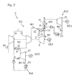
Fig. 2 is a block diagram showing a modification of the gas turbine engine system inFig. 1 . - Hereinafter, embodiments of the present invention will be described with reference to the drawings.
Fig. 1 is a schematic configuration diagram showing a gas turbine engine system (hereinafter, referred to simply as "engine system") E according to an embodiment of the present invention. The engine system E includes three engine units, namely, a gas turbine engine unit GU, a first Rankine cycle engine unit RU1, and a second Rankine cycle engine unit RU2, and those engine units GU, RU1, RU2 drive respective loads such as generators GE1, GE2, GE3. - The gas turbine engine unit GU includes a compressor 1 which compresses a first working medium M1, a
combustor 3 which is a heater for heating the first working medium M1 compressed by the compressor 1, and afirst turbine 5 which outputs power from the combusted first working medium M1. In the present embodiment, an air may be used as the first working medium M1. - The compressor 1 includes a low-
pressure compression part 1a and a high-pressure compression part 1b, and is provided with anintermediate cooler 9 arranged between the low-pressure compression part 1a and the high-pressure compression part 1b. By cooling the first working medium M1, compressed by the low-pressure compression part 1a, with theintermediate cooler 9, compression work of the high-pressure compression part 1b is reduced, and the efficiency is improved. The high-pressure first working medium M1 discharged from the compressor 1 passes through aregenerative heat exchanger 13 and then is sent to thecombustor 3. Theregenerative heat exchanger 13 preheats the first working medium M1 flowing from the compressor 1 toward thecombustor 3 by using the heat of the high-temperature first working medium M1 discharged from thefirst turbine 5. - A
heat exchanger 15 is further provided on a downstream of theregenerative heat exchanger 13 on adischarge path 11 which discharges the first working medium M1 discharged from thefirst turbine 5 to the outside. The first working medium M1 discharged from theregenerative heat exchanger 13 passes through theheat exchanger 15 as a heating medium and then is discharged to the outside. - In the first Rankine cycle engine unit RU1, a
second turbine 17 is driven by a second working medium M2 which has been heated into a gaseous state utilizing, as a heat source, the heat of the first working medium M1 passing through theintermediate cooler 9, and power is outputted through thesecond turbine 17. The second working medium M2 discharged from thesecond turbine 17 is condensed by afirst condenser 19 and then is supplied to theintermediate cooler 9 and thesecond turbine 17 again. - The first Rankine cycle engine unit RU1 is configured as an organic Rankine cycle engine using an organic substance as the second working medium M2. In particular, the temperature of the first working medium M1 that is being compressed in the compressor 1 is about 100°C to 200°C, which is relatively low, thus an organic medium having a low boiling point may be used as the second working medium M2. In this example, a fluorocarbon-based organic medium, for example, HFC-134a, HFC-245fa, HFC-365mfc, or the like, may be used.
- In the second Rankine cycle engine unit RU2, a
third turbine 21 is driven by a third working medium M3 which has been heated utilizing, as a heat source, the heat of the first working medium M1 passing through theheat exchanger 15 as a heating medium as described above, and power is outputted through thethird turbine 21. The third working medium M3 discharged from thethird turbine 21 is condensed by asecond condenser 23 and then is supplied to theheat exchanger 15 and thethird turbine 21 again. - The second Rankine cycle engine unit RU2 is also configured as an organic Rankine cycle engine using an organic substance as the third working medium M3. The first working medium M1, which is an exhaust gas discharged from the
first turbine 5, is kept at a relatively high temperature of about 200°C to 300°C even after passing through theregenerative heat exchanger 13, thus it is possible to use an organic medium having a higher boiling point than that of the second working medium M2. In this example, a petroleum-based organic medium, for example, butane or pentane, may be used. - The second Rankine cycle engine unit RU2 may be configured as an ordinary steam turbine using water as the third working medium M3. Alternatively, the second Rankine cycle engine unit RU2 may be omitted, but the organic media are used as in the present embodiment, not only the heat of the first working medium M1 passing through the compressor 1 but also the heat of the first working medium M1 discharged from the
first turbine 5 are used to output power, and thus it is possible to obtain further high efficiency for the entire engine system E. - In addition, as a modification of the present embodiment, as shown in
Fig. 2 , asolar heater 31 which uses sunlight SL as a heat source may be additionally provided at the upstream side of thecombustor 3 as a heater which heats the first working medium M1 compressed by the compressor 1. By providing such a configuration and heating the first working medium M1 again by using the sunlight SL which is natural energy, the efficiency of the engine system E is further improved. - As described above, in the engine system E according to the present embodiment, since the organic substance having a low boiling point is used as the working medium M2 of the Rankine cycle engine (in particular, the first Rankine cycle engine RU1) combined with the gas turbine engine unit GU, it is possible to effectively use the heat of the relatively-low-temperature working medium passing through the compressor 1, and thus it is possible to obtain very high efficiency for the entire engine system E.
- Although the present invention has been described above in connection with the embodiments thereof with reference to the accompanying drawings, numerous additions, changes, or deletions can be made without departing from the gist of the present invention. Accordingly, such additions, changes, or deletions are to be construed as included in the scope of the present invention.
-
- 1
- Compressor
- 3
- Combustor (heater)
- 5
- First turbine
- 9
- Intermediate cooler
- 13
- Regenerative heat exchanger
- 15
- Heat exchanger
- 31
- Solar heater
- E
- Gas turbine engine system
- GU
- Gas turbine engine unit
- RU1
- First Rankine cycle engine unit
- RU2
- Second Rankine cycle engine unit
- M1
- First working medium
- M2
- Second working medium
- M3
- Third working medium
Claims (3)
- A gas turbine engine system comprising:a compressor configured to compress a first working medium;a heater configured to heat the compressed first working medium utilizing an external heat source;a turbine configured to output power from the first working medium;an intermediate cooler provided at the compressor and configured to cool the first working medium compressed by a low-pressure compression part of the compressor and supply the first working medium to a high-pressure compression part of the compressor; andan organic Rankine cycle engine using, as a second working medium, an organic substance which serves as a cooling medium of the intermediate cooler.
- The gas turbine engine system as claimed in claim 1, further comprising:a heat exchanger provided on a discharge path for discharging the first working medium discharged from the turbine, the heat exchanger using, as a heating medium, the first working medium discharged from the turbine; andan organic Rankine cycle engine using, as a third working medium, an organic substance which serves as a heat receiving medium of the heat exchanger.
- The gas turbine engine system as claimed in claim 1 comprising, as the heater, a solar heater configured to heat the first working medium utilizing sunlight as a heat source.
Applications Claiming Priority (2)
| Application Number | Priority Date | Filing Date | Title |
|---|---|---|---|
| JP2012086210A JP2013217214A (en) | 2012-04-05 | 2012-04-05 | Gas turbine engine system using organic medium |
| PCT/JP2013/060040 WO2013151029A1 (en) | 2012-04-05 | 2013-04-02 | Gas turbine engine system that uses organic medium |
Publications (1)
| Publication Number | Publication Date |
|---|---|
| EP2835515A1 true EP2835515A1 (en) | 2015-02-11 |
Family
ID=49300510
Family Applications (1)
| Application Number | Title | Priority Date | Filing Date |
|---|---|---|---|
| EP13771883.9A Withdrawn EP2835515A1 (en) | 2012-04-05 | 2013-04-02 | Gas turbine engine system that uses organic medium |
Country Status (6)
| Country | Link |
|---|---|
| US (1) | US20150075133A1 (en) |
| EP (1) | EP2835515A1 (en) |
| JP (1) | JP2013217214A (en) |
| CN (1) | CN104204458A (en) |
| CA (1) | CA2869388A1 (en) |
| WO (1) | WO2013151029A1 (en) |
Cited By (2)
| Publication number | Priority date | Publication date | Assignee | Title |
|---|---|---|---|---|
| EP3889399A1 (en) * | 2020-03-30 | 2021-10-06 | Xuanhua Guo | Combined system of intercooled recuperative gas turbine and refrigerant compound bottoming cycle |
| KR20220130550A (en) * | 2021-03-18 | 2022-09-27 | 수안후아 구오 | Integrated system of intermediate cooling regenerative gas turbine and refrigerant combined sub-cycle |
Families Citing this family (12)
| Publication number | Priority date | Publication date | Assignee | Title |
|---|---|---|---|---|
| WO2014174789A1 (en) | 2013-04-22 | 2014-10-30 | パナソニックIpマネジメント株式会社 | Combined heat and power system |
| JP6221176B2 (en) * | 2013-12-09 | 2017-11-01 | 三菱日立パワーシステムズ株式会社 | GAS TURBINE COOLING SYSTEM, GAS TURBINE PLANT EQUIPPED WITH THE GAS TURBINE COOLING SYSTEM, AND METHOD FOR COOLING HOT TEMPERATURE SECTION OF GAS TURBINE |
| CN103953447A (en) * | 2014-05-15 | 2014-07-30 | 中国船舶重工集团公司第七�三研究所 | Intercooled cycle gas turbine capable of generating electricity by utilizing waste heat of low-pressure gas compressor |
| CN103939215A (en) * | 2014-05-15 | 2014-07-23 | 中国船舶重工集团公司第七�三研究所 | Organic Rankin cycle generation device using residual heat of gas turbine |
| JP6242769B2 (en) * | 2014-08-21 | 2017-12-06 | 株式会社神戸製鋼所 | Compression device |
| CN104454048A (en) * | 2014-10-18 | 2015-03-25 | 杭州哲达科技股份有限公司 | ORC expansion recycling method and device of waste heat of air compressor set |
| CN104879178A (en) * | 2015-05-26 | 2015-09-02 | 阮炯明 | Method and system for generating power through high-pressure cryogenic fluid, recycling low-grade waste heat and cooling compressor inlet gas |
| CN105508055B (en) * | 2015-11-27 | 2018-01-02 | 中国能源建设集团广东省电力设计研究院有限公司 | The system and method for distributed busbar protection cooling circulating water |
| CN105649776A (en) * | 2016-01-19 | 2016-06-08 | 扬州市新港电机有限公司 | Gas power generation system based on SiC device |
| DE112017001619T5 (en) * | 2016-03-29 | 2018-12-20 | Mitsubishi Heavy Industries, Ltd. | Gas turbine plant and operating method for it |
| CN108869212A (en) * | 2018-06-29 | 2018-11-23 | 枣庄市牧天牛养殖开发有限公司 | The energy conservation of All-weather clean energy resource comprehensive electric generating and facility preparation method |
| KR102569574B1 (en) * | 2023-01-31 | 2023-08-25 | 주식회사 휴처스 | Temperature difference power generation system using solar collected heat |
Family Cites Families (21)
| Publication number | Priority date | Publication date | Assignee | Title |
|---|---|---|---|---|
| JPS5453731A (en) * | 1977-10-07 | 1979-04-27 | Sumitomo Heavy Ind Ltd | Waste heat recovery unit |
| JPS57164193A (en) * | 1981-04-03 | 1982-10-08 | Nippon Kokan Kk <Nkk> | Working fluid for waste heat recovery |
| JPS57173512A (en) * | 1981-04-17 | 1982-10-25 | Hitachi Ltd | Power generating plant |
| DE3224577A1 (en) * | 1982-07-01 | 1984-01-05 | Rudolf Dr. 6800 Mannheim Wieser | Combined gas turbine/steam turbine plant |
| US4942736A (en) * | 1988-09-19 | 1990-07-24 | Ormat Inc. | Method of and apparatus for producing power from solar energy |
| US5687570A (en) * | 1994-02-28 | 1997-11-18 | Ormat Industries Ltd. | Externally fired combined cycle gas turbine system |
| US6167706B1 (en) * | 1996-01-31 | 2001-01-02 | Ormat Industries Ltd. | Externally fired combined cycle gas turbine |
| US5704209A (en) * | 1994-02-28 | 1998-01-06 | Ormat Industries Ltd | Externally fired combined cycle gas turbine system |
| US5799490A (en) * | 1994-03-03 | 1998-09-01 | Ormat Industries Ltd. | Externally fired combined cycle gas turbine |
| US6510695B1 (en) * | 1999-06-21 | 2003-01-28 | Ormat Industries Ltd. | Method of and apparatus for producing power |
| JP2000204909A (en) * | 1999-01-11 | 2000-07-25 | Osaka Gas Co Ltd | Liquefied natural gas cold energy power generator |
| WO2002090747A2 (en) * | 2001-05-07 | 2002-11-14 | Battelle Memorial Institute | Heat energy utilization system |
| JP2007159225A (en) | 2005-12-02 | 2007-06-21 | Kawasaki Heavy Ind Ltd | Microgrid using high performance secondary batteries |
| JP2007187047A (en) * | 2006-01-12 | 2007-07-26 | Mitsubishi Heavy Ind Ltd | Gas turbine combined cycle plant used in combination with steam turbine plant |
| JP5083836B2 (en) * | 2009-07-06 | 2012-11-28 | 国立大学法人長岡技術科学大学 | Heat engine cycle multi-connection system |
| JP5540660B2 (en) * | 2009-11-16 | 2014-07-02 | 株式会社Ihi | Heat recovery system for rotating machine |
| US8327641B2 (en) * | 2009-12-01 | 2012-12-11 | General Electric Company | System for generation of power using solar energy |
| US20120017597A1 (en) * | 2010-07-23 | 2012-01-26 | General Electric Company | Hybrid power generation system and a method thereof |
| US20130081395A1 (en) * | 2011-09-29 | 2013-04-04 | General Electric Company | System and method for generating electric power |
| JP5555276B2 (en) * | 2012-04-05 | 2014-07-23 | 川崎重工業株式会社 | Gas turbine engine device equipped with Rankine cycle engine |
| JP2015094344A (en) * | 2013-11-14 | 2015-05-18 | 三菱日立パワーシステムズ株式会社 | Gas turbine cooling system, gas turbine plant with gas turbine cooling system, and method of cooling gas turbine high-temperature part |
-
2012
- 2012-04-05 JP JP2012086210A patent/JP2013217214A/en active Pending
-
2013
- 2013-04-02 CN CN201380018445.6A patent/CN104204458A/en active Pending
- 2013-04-02 WO PCT/JP2013/060040 patent/WO2013151029A1/en not_active Ceased
- 2013-04-02 EP EP13771883.9A patent/EP2835515A1/en not_active Withdrawn
- 2013-04-02 US US14/390,296 patent/US20150075133A1/en not_active Abandoned
- 2013-04-02 CA CA2869388A patent/CA2869388A1/en not_active Abandoned
Non-Patent Citations (1)
| Title |
|---|
| See references of WO2013151029A1 * |
Cited By (2)
| Publication number | Priority date | Publication date | Assignee | Title |
|---|---|---|---|---|
| EP3889399A1 (en) * | 2020-03-30 | 2021-10-06 | Xuanhua Guo | Combined system of intercooled recuperative gas turbine and refrigerant compound bottoming cycle |
| KR20220130550A (en) * | 2021-03-18 | 2022-09-27 | 수안후아 구오 | Integrated system of intermediate cooling regenerative gas turbine and refrigerant combined sub-cycle |
Also Published As
| Publication number | Publication date |
|---|---|
| CN104204458A (en) | 2014-12-10 |
| WO2013151029A1 (en) | 2013-10-10 |
| US20150075133A1 (en) | 2015-03-19 |
| JP2013217214A (en) | 2013-10-24 |
| CA2869388A1 (en) | 2013-10-10 |
Similar Documents
| Publication | Publication Date | Title |
|---|---|---|
| US20150075133A1 (en) | Gas turbine engine system that uses organic medium | |
| EP2857641B1 (en) | Gas turbine engine system equipped with rankine cycle engine | |
| US9410451B2 (en) | Gas turbine engine with integrated bottoming cycle system | |
| CN106574552B (en) | Power generation system with partially recycled flow path and method | |
| AU2009339444B2 (en) | Conversion of combined cycle power plant to compressed air energy storage power plant | |
| JP6702636B2 (en) | Power generation system and method for generating power | |
| US8881528B2 (en) | System for the generation of mechanical and/or electrical energy | |
| US20110233940A1 (en) | Solar-thermal gas turbine generator | |
| KR101705657B1 (en) | Electricity Generation Device and Method | |
| US20130269334A1 (en) | Power plant with closed brayton cycle | |
| JP2018523045A (en) | Simple cycle system and method for waste heat recovery | |
| CA2673721A1 (en) | Power augmentation of combustion turbines by injection of cold air upstream of compressor | |
| TN2013000116A1 (en) | Solar thermal power system | |
| EP3408506B1 (en) | Combined cycle power plant | |
| JP6417565B2 (en) | External combustion Brayton cycle engine using solar heat | |
| WO2008010202A3 (en) | Improved thermal to electrical energy converter | |
| RU2012149900A (en) | COGENERATION GAS-TURBINE POWER INSTALLATION | |
| RU139584U1 (en) | COMPRESSOR STATION FOR TRANSPORTING NATURAL GAS | |
| Al-Sulaiman et al. | Energy and exergy assessments of a new trigeneration system based on organic rankine cycle and biomass combustor | |
| CZ29359U1 (en) | Arrangement of pressure limiting station for generation of cold and electric power |
Legal Events
| Date | Code | Title | Description |
|---|---|---|---|
| PUAI | Public reference made under article 153(3) epc to a published international application that has entered the european phase |
Free format text: ORIGINAL CODE: 0009012 |
|
| 17P | Request for examination filed |
Effective date: 20141105 |
|
| AK | Designated contracting states |
Kind code of ref document: A1 Designated state(s): AL AT BE BG CH CY CZ DE DK EE ES FI FR GB GR HR HU IE IS IT LI LT LU LV MC MK MT NL NO PL PT RO RS SE SI SK SM TR |
|
| AX | Request for extension of the european patent |
Extension state: BA ME |
|
| DAX | Request for extension of the european patent (deleted) | ||
| STAA | Information on the status of an ep patent application or granted ep patent |
Free format text: STATUS: THE APPLICATION HAS BEEN WITHDRAWN |
|
| 18W | Application withdrawn |
Effective date: 20150817 |