EP2835331A1 - Sheet processing apparatus and image forming apparatus - Google Patents
Sheet processing apparatus and image forming apparatus Download PDFInfo
- Publication number
- EP2835331A1 EP2835331A1 EP14179625.0A EP14179625A EP2835331A1 EP 2835331 A1 EP2835331 A1 EP 2835331A1 EP 14179625 A EP14179625 A EP 14179625A EP 2835331 A1 EP2835331 A1 EP 2835331A1
- Authority
- EP
- European Patent Office
- Prior art keywords
- sheet
- rotating member
- drive
- endless belt
- processing apparatus
- Prior art date
- Legal status (The legal status is an assumption and is not a legal conclusion. Google has not performed a legal analysis and makes no representation as to the accuracy of the status listed.)
- Granted
Links
- 238000012545 processing Methods 0.000 title claims abstract description 80
- 238000000034 method Methods 0.000 claims description 8
- 230000002093 peripheral effect Effects 0.000 claims description 7
- 230000008569 process Effects 0.000 claims description 7
- 230000005540 biological transmission Effects 0.000 claims description 4
- 238000012546 transfer Methods 0.000 description 36
- 238000001514 detection method Methods 0.000 description 6
- 238000010586 diagram Methods 0.000 description 4
- 101000661807 Homo sapiens Suppressor of tumorigenicity 14 protein Proteins 0.000 description 3
- 230000015572 biosynthetic process Effects 0.000 description 3
- 230000008859 change Effects 0.000 description 3
- 230000001771 impaired effect Effects 0.000 description 3
- 230000015556 catabolic process Effects 0.000 description 2
- 239000003086 colorant Substances 0.000 description 2
- 238000006731 degradation reaction Methods 0.000 description 2
- 230000007246 mechanism Effects 0.000 description 2
- 230000000903 blocking effect Effects 0.000 description 1
- 210000000078 claw Anatomy 0.000 description 1
- 238000004891 communication Methods 0.000 description 1
- 230000001276 controlling effect Effects 0.000 description 1
- 230000002452 interceptive effect Effects 0.000 description 1
- 230000014759 maintenance of location Effects 0.000 description 1
- 238000012986 modification Methods 0.000 description 1
- 230000004048 modification Effects 0.000 description 1
- 230000001105 regulatory effect Effects 0.000 description 1
- 238000007665 sagging Methods 0.000 description 1
- 238000011144 upstream manufacturing Methods 0.000 description 1
Images


Classifications
-
- B—PERFORMING OPERATIONS; TRANSPORTING
- B65—CONVEYING; PACKING; STORING; HANDLING THIN OR FILAMENTARY MATERIAL
- B65H—HANDLING THIN OR FILAMENTARY MATERIAL, e.g. SHEETS, WEBS, CABLES
- B65H5/00—Feeding articles separated from piles; Feeding articles to machines
- B65H5/02—Feeding articles separated from piles; Feeding articles to machines by belts or chains, e.g. between belts or chains
- B65H5/021—Feeding articles separated from piles; Feeding articles to machines by belts or chains, e.g. between belts or chains by belts
- B65H5/026—Feeding articles separated from piles; Feeding articles to machines by belts or chains, e.g. between belts or chains by belts between belts and stationary pressing, supporting or guiding elements forming a transport nip
-
- B—PERFORMING OPERATIONS; TRANSPORTING
- B65—CONVEYING; PACKING; STORING; HANDLING THIN OR FILAMENTARY MATERIAL
- B65H—HANDLING THIN OR FILAMENTARY MATERIAL, e.g. SHEETS, WEBS, CABLES
- B65H31/00—Pile receivers
- B65H31/34—Apparatus for squaring-up piled articles
- B65H31/36—Auxiliary devices for contacting each article with a front stop as it is piled
-
- B—PERFORMING OPERATIONS; TRANSPORTING
- B65—CONVEYING; PACKING; STORING; HANDLING THIN OR FILAMENTARY MATERIAL
- B65H—HANDLING THIN OR FILAMENTARY MATERIAL, e.g. SHEETS, WEBS, CABLES
- B65H3/00—Separating articles from piles
- B65H3/02—Separating articles from piles using friction forces between articles and separator
- B65H3/04—Endless-belt separators
- B65H3/045—Endless-belt separators for separating substantially vertically stacked articles
-
- B—PERFORMING OPERATIONS; TRANSPORTING
- B65—CONVEYING; PACKING; STORING; HANDLING THIN OR FILAMENTARY MATERIAL
- B65H—HANDLING THIN OR FILAMENTARY MATERIAL, e.g. SHEETS, WEBS, CABLES
- B65H3/00—Separating articles from piles
- B65H3/02—Separating articles from piles using friction forces between articles and separator
- B65H3/04—Endless-belt separators
- B65H3/047—Endless-belt separators separating from the top of a pile
-
- B—PERFORMING OPERATIONS; TRANSPORTING
- B65—CONVEYING; PACKING; STORING; HANDLING THIN OR FILAMENTARY MATERIAL
- B65H—HANDLING THIN OR FILAMENTARY MATERIAL, e.g. SHEETS, WEBS, CABLES
- B65H2402/00—Constructional details of the handling apparatus
- B65H2402/30—Supports; Subassemblies; Mountings thereof
- B65H2402/31—Pivoting support means
-
- B—PERFORMING OPERATIONS; TRANSPORTING
- B65—CONVEYING; PACKING; STORING; HANDLING THIN OR FILAMENTARY MATERIAL
- B65H—HANDLING THIN OR FILAMENTARY MATERIAL, e.g. SHEETS, WEBS, CABLES
- B65H2403/00—Power transmission; Driving means
- B65H2403/40—Toothed gearings
- B65H2403/42—Spur gearing
-
- B—PERFORMING OPERATIONS; TRANSPORTING
- B65—CONVEYING; PACKING; STORING; HANDLING THIN OR FILAMENTARY MATERIAL
- B65H—HANDLING THIN OR FILAMENTARY MATERIAL, e.g. SHEETS, WEBS, CABLES
- B65H2403/00—Power transmission; Driving means
- B65H2403/40—Toothed gearings
- B65H2403/44—Internal gearing
-
- B—PERFORMING OPERATIONS; TRANSPORTING
- B65—CONVEYING; PACKING; STORING; HANDLING THIN OR FILAMENTARY MATERIAL
- B65H—HANDLING THIN OR FILAMENTARY MATERIAL, e.g. SHEETS, WEBS, CABLES
- B65H2404/00—Parts for transporting or guiding the handled material
- B65H2404/20—Belts
- B65H2404/26—Particular arrangement of belt, or belts
- B65H2404/265—Arrangement of belt forming a deformable ring, e.g. driven in the nip of a roller pair
-
- B—PERFORMING OPERATIONS; TRANSPORTING
- B65—CONVEYING; PACKING; STORING; HANDLING THIN OR FILAMENTARY MATERIAL
- B65H—HANDLING THIN OR FILAMENTARY MATERIAL, e.g. SHEETS, WEBS, CABLES
- B65H2404/00—Parts for transporting or guiding the handled material
- B65H2404/20—Belts
- B65H2404/26—Particular arrangement of belt, or belts
- B65H2404/268—Arrangement of belts facing a transport surface, e.g. contact glass in copy machine
- B65H2404/2682—Arrangement of belts facing a transport surface, e.g. contact glass in copy machine means for engaging/disengaging with/from transport surface
-
- B—PERFORMING OPERATIONS; TRANSPORTING
- B65—CONVEYING; PACKING; STORING; HANDLING THIN OR FILAMENTARY MATERIAL
- B65H—HANDLING THIN OR FILAMENTARY MATERIAL, e.g. SHEETS, WEBS, CABLES
- B65H2404/00—Parts for transporting or guiding the handled material
- B65H2404/20—Belts
- B65H2404/26—Particular arrangement of belt, or belts
- B65H2404/269—Particular arrangement of belt, or belts other arrangements
- B65H2404/2693—Arrangement of belts on movable frame
-
- B—PERFORMING OPERATIONS; TRANSPORTING
- B65—CONVEYING; PACKING; STORING; HANDLING THIN OR FILAMENTARY MATERIAL
- B65H—HANDLING THIN OR FILAMENTARY MATERIAL, e.g. SHEETS, WEBS, CABLES
- B65H2555/00—Actuating means
- B65H2555/20—Actuating means angular
-
- B—PERFORMING OPERATIONS; TRANSPORTING
- B65—CONVEYING; PACKING; STORING; HANDLING THIN OR FILAMENTARY MATERIAL
- B65H—HANDLING THIN OR FILAMENTARY MATERIAL, e.g. SHEETS, WEBS, CABLES
- B65H2801/00—Application field
- B65H2801/24—Post -processing devices
- B65H2801/27—Devices located downstream of office-type machines
Abstract
Description
- This disclosure relates to a sheet processing apparatus and an image forming apparatus.
- In the related art, an image forming apparatus such as a copier, a printer, a facsimile, and a multi-function printer includes a type provided with a sheet processing apparatus in a main body of the image forming apparatus and configured to perform processing such as binding or the like on sheets discharged from the main body of the image forming apparatus. Example of the sheet processing apparatus as described above includes a type configured to discharge a sheet discharged from the main body of the image forming apparatus once into a process tray, align the sheet with a sheet already stacked on the process tray, bind the sheets if needed in the process tray, and then discharge the processed sheets on a stacking tray as described in Japanese Patent Laid-Open No.
2003-128315 -
Figs. 13A and 13B are drawings illustrating a configuration of the sheet processing apparatus of the related art as described above. As illustrated inFigs. 13A and 13B , atrailing end stopper 108 configured to stop and position the sheet(s) P is provided at an end of anintermediate processing tray 107. The sheet P discharged onto theintermediate processing tray 107 by asheet discharge roller 103 is conveyed by an endlessknurled belt 1161 configured to be rotated by thesheet discharge roller 103, and aligned at trailing ends thereof by abutting against the trailingend stopper 108. - The shape of the
knurled belt 1161 is changed by an moving roller X. - That is, as illustrated in
Fig. 13A , if there is no sheet bundle on theintermediate processing tray 107, the moving roller X does not move. In this case, theknurled belt 1161 is not deformed and rotates in a state of being in contact with theintermediate processing tray 107. In contrast, when a plurality of sheets P are stacked on the intermediate processing tray, the moving roller X moves to deform the shape of theknurled belt 1161 as illustrated inFig. 13B , so that a pressure as constant as possible is applied from theknurled belt 1161 to a sheet bundle PA. - In the sheet processing apparatus of the related art as described above, when the
knurled belt 1161 is deformed, the distance between thesheet discharge roller 103 and the moving roller X changes. Therefore, tensile force of theknurled belt 1161 is increased in comparison with the case where the number of stacked sheets is small.
When the tensile force is increased, a conveying force of theknurled belt 1161 increases correspondingly. When the conveying force is increased, the sheet P in abutment with the trailingend stopper 108 may be bent between theknurled belt 1161 and the trailingend stopper 108 and, consequently, alignment of the sheet may be impaired. - As a countermeasure, a method of controlling the amount of movement of the moving roller X by considering a change in tensile force of the
knurled belt 1161 is conceivable. However, if the hardness of theknurled belt 1161 is changed by a change in atmospheric temperature or time degradation, a deviation occurs between the amount of movement of the moving roller X and the conveying force. This deviation is increased with increase in amount of movement. Accordingly, when an actual conveying force is smaller than a desired conveying force, the sheet P does not reach thetrailing end stopper 108. In contrast, when the actual conveying force is larger than the desired conveying force, the sheet P is bent between theknurled belt 1161 and the trailingend stopper 108 and, consequently, alignment is impaired. - The present invention in its first aspect provides a sheet processing apparatus as specified in
claims 1 through 12. The present invention in its second aspect provides a sheet processing apparatus as specified in claims 13 and 14. The present invention in its third aspect provides an image forming apparatus as specified in claim 15. - Further features of the present invention will become apparent from the following description of exemplary embodiments with reference to the attached drawings. The accompanying drawings, which are incorporated in and constitute a part of the specification, illustrate exemplary embodiments, features, and aspects of the invention and, together with the description, serve to explain the principles of the invention.
-
-
Fig. 1 is a drawing illustrating a configuration of an image forming apparatus provided with a sheet processing apparatus of a first embodiment. -
Fig. 2A is a schematic drawing illustrating a state of a finisher with a sheet conveyed by a sheet discharge roller. -
Fig. 2B is a schematic drawing illustrating a state of the finisher with a sheet discharged into an intermediate processing tray. -
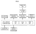
Fig. 3 is a control block diagram of the image forming apparatus. -
Fig. 4 is a control block diagram of the finisher. -
Fig. 5A is an explanatory drawing illustrating a sheet binding operation of the finisher. -
Fig. 5B is a schematic drawing illustrating a state of the finisher with a bound sheet bundle being discharged to a stacking tray. -
Fig. 5C is a schematic drawing illustrating a state of the finisher with the sheet bundle discharged to the stacking tray. -
Fig. 6A is a perspective view illustrating a configuration of a knurled belt portion provided on the finisher. -
Fig. 6B is an enlarged view of the knurled belt portion illustrated inFig. 6A . -
Fig. 7A is a side view illustrating a configuration of the knurled belt portion. -
Fig. 7B is a side view illustrating a gear mechanism of the knurled belt portion illustrated inFig. 7A . -
Fig. 8A is a schematic view illustrating a state of the knurled belt portion with a knurled belt moved downward to a large extent. -
Fig. 8B is a schematic drawing illustrating the state of the knurled belt portion with the knurled belt lowered to a medium extent. -
Fig. 8C is a schematic drawing illustrating the state of the knurled belt portion with the knurled belt lowered to a small extent. -
Fig. 9 is a flowchart for explaining a sheet processing operation of the finisher; -
Fig. 10 is a schematic drawing illustrating a configuration of the knurled belt portion provided in a sheet processing apparatus of a second embodiment. -
Fig. 11A is a drawing illustrating a configuration of the knurled belt portion of the second embodiment. -
Fig. 11B is a side view illustrating a gear mechanism of the knurled belt portion illustrated inFig. 11A . -
Fig. 12A is a schematic view illustrating a state of the knurled belt portion of the second embodiment with a knurled belt lowered to a large extent. -
Fig. 12B is a schematic drawing illustrating the state of the knurled belt portion of the second embodiment with the knurled belt lowered to a medium extent. -
Fig. 12C is a schematic drawing illustrating the state of the knurled belt portion of the second embodiment with the knurled belt lowered to a small extent. -
Fig. 13A is a schematic drawing illustrating a knurled belt of a sheet processing apparatus of the related art. -
Fig. 13B is a schematic drawing illustrating a state in which the knurled belt illustrated inFig. 13A is deformed. - Hereinafter, embodiments of the present invention will be described in detail with reference to the drawings.
Fig. 1 is a drawing illustrating a configuration of an image forming apparatus provided with a sheet processing apparatus of a first embodiment. InFig. 1 ,reference numeral 900 denotes an image forming apparatus,reference numeral 900A denotes a main body of the image forming apparatus (hereinafter referred to as apparatus main body), and reference numeral 900B denotes an image forming portion configured to form image on a sheet.Reference numeral 950 denotes an image reading apparatus provided on the top of the apparatusmain body 900A and provided with adocument feeder 950A, andreference numeral 100 denotes a finisher, i.e., a sheet processing apparatus, arranged between the upper surface of the apparatusmain body 900A and animage reading apparatus 950. - Here, the
image forming portion 900B includes photoconductive drums (a) through (d) configured to form toner images in four colors, namely, yellow, magenta, cyan, and black, and an exposingunit 906 configured to radiate a laser beam on the basis of image information and form electrostatic latent images on the photoconductive drums. The photoconductive drums (a) through (d) are driven by a motor, not illustrated. Each photoconductive drum is provided with a primary charger, a developing unit and a transfer charger arranged in the periphery thereof and is unitized with them asprocess cartridges 901a through 901d. - The
image forming portion 900B includes anintermediate transfer belt 902 driven and rotated in a direction indicated by an arrow, and asecondary transfer portion 903 configured to transfer a full-color image formed on theintermediate transfer belt 902 in sequence to a sheet P. By applying a transfer bias to theintermediate transfer belt 902 bytransfer chargers 902a through 902d, the respective color toner images on the photoconductive drums are sequentially transferred to theintermediate transfer belt 902 in a superimposed manner. Accordingly, a full-color image is formed on the intermediate transfer belt. - The
secondary transfer portion 903 includes a secondarytransfer counter roller 903b configured to support theintermediate transfer belt 902 and asecondary transfer roller 903a configured to abut against the secondarytransfer counter roller 903b through theintermediate transfer belt 902. InFig. 1 ,reference numeral 909 denotes a registration roller,reference numeral 904 denotes a sheet feed cassette,reference numeral 908 denotes a pickup roller configured to feed the sheet P stored in thesheet feed cassette 904. - Next, an image forming operation of the
image forming apparatus 900 having the above-described configuration will be described. When the image forming operation is started, first of all, the exposingunit 906 radiates a laser beam on the basis of image information from a personal computer or the like, not illustrated, and exposes surfaces of the photoconductive drums (a) through (d), the photoconductive drums (a) through (d) being uniformly charged to predetermined polarity and potential in sequence, and forms electrostatic latent images on the photoconductive drums (a) through (d) respectively. Subsequently, the electrostatic latent images are developed and visualized by toner. - For example, the photoconductive drum (a) is irradiated with a laser beam on the basis of an image signal having a yellow color component of an document via a polygon mirror or the like of the exposing
unit 906 to form an electrostatic latent image of yellow on the photoconductive drum (a). The electrostatic latent image of yellow is developed by yellow toner from a developing unit and hence is visualized as a yellow toner image. Subsequently, the toner image arrives at a primary transfer portion where the photoconductive drum (a) and theintermediate transfer belt 902 come into contact with each other in association with the rotation of the photoconductive drum (a). When the toner image arrives at the first transfer portion, the yellow toner image on the photoconductive drum (a) is transferred to theintermediate transfer belt 902 by a primary transfer bias applied to thetransfer charger 902a (primary transfer). - Subsequently, when the portion of the
intermediate transfer belt 902 carrying the yellow toner image moves, a magenta toner image formed on the photoconductive drum (b) in the same manner as describe above by this time is transferred to theintermediate transfer belt 902 over the yellow toner image. In the same manner, as theintermediate transfer belt 902 moves, a cyan toner image and a black toner image are transferred over the yellow toner image and the magenta toner image in a superimposed manner at respective primary transfer portions. Accordingly, a full-color toner image is formed on theintermediate transfer belt 902. - In parallel to the toner image forming operation, the sheets P stored in the
sheet feed cassette 904 are fed by thepickup roller 908 one by one. Next, the sheet P arrives at aregistration roller 909 and is conveyed to thesecondary transfer portion 903 at timing adjusted byregistration roller 909 with the toner image. Subsequently, the toner image of four colors on theintermediate transfer belt 902 is transferred at once to the sheet P by the secondary transfer bias applied to thesecondary transfer roller 903a, i.e., the transfer portion, in the secondary transfer portion 903 (secondary transfer). - Subsequently, the sheet P having the toner image transferred thereto is conveyed from the
secondary transfer portion 903 to a fixingportion 905 while being guided by aconveyance guide 920 and receives heat and pressure so that the image is fixed when the sheet p passes through the fixingportion 905. Subsequently, the sheet P having the image fixed thereto passes through adischarge passage 921 provided on the downstream of the fixingportion 905, and then is discharged by adischarge roller pair 918, and is conveyed to thefinisher 100. - The
finisher 100 receives the sheet P discharged from the apparatusmain body 900A in sequence as illustrated inFigs. 2A and 2B , and performs a process of aligning and bundling a plurality of received sheets into one bundle and a process of binding the bundled sheet bundle at upstream end in a sheet discharge direction (hereinafter, referred to as "trailing end"). As illustrated inFigs.5A through 5C , thefinisher 100 is provided with aprocessing portion 139 configured to perform binding as needed and discharge and stack the sheet bundle on a stackingtray 114. Theprocessing portion 139 includes anintermediate processing tray 107 as a sheet stacking portion configured to stack the sheet to be bound and abinding portion 100A provided with astapler 110 configured to bind (staple) the sheets stacked on theintermediate processing tray 107 and a staple-less binding portion, not illustrated. - The
intermediate processing tray 107 is provided with front and back aligningplates intermediate processing tray 107 from a direction orthogonal to the depth direction of the apparatusmain body 900A.
The front and back aligningplates intermediate processing tray 107 are driven by an alignment motor M253 illustrated inFig. 4 described later, and move in the width direction. - The front and back aligning
plates intermediate processing tray 107, the alignment motor M253 is driven to move the front and back aligningplates intermediate processing tray 107. - A take-in
paddle 106 and aknurled belt portion 116 are arranged above theintermediate processing tray 107. The take-inpaddle 106 is configured to be moved downward by driving of the puddle lifting motor M252 illustrated inFig. 4 descried later when the sheet is discharged to theintermediate processing tray 107, and rotates counterclockwise at the right timing by a paddle motor, not illustrated. Accordingly, the sheet P is conveyed toward theknurled belt portion 116. The take-inpaddle 106 is configured to be moved upward to a HP (home position) not disturbing the discharged sheet by reverse driving of the puddle lifting motor M252 on the basis of the detection information detected by the puddle HP sensor S243 before the sheet is conveyed to theprocessing portion 139. - The
knurled belt portion 116 includes aknurled belt 1161, i.e., an endless sheet conveyance portion (endless belt), rotated by a conveyance motor M250 illustrated inFig. 4 and described later, and configured to convey the sheet stacked in theintermediate processing tray 107 in contact with the upper surface thereof. When the sheet P is conveyed by the take-inpaddle 106, the sheet P is drawn by theknurled belt 1161, is conveyed toward the trailingend stopper 108 as an aligning portion configured to align the position of the sheet P in the sheet conveying direction, and is aligned with the sheets already stacked on theintermediate processing tray 107 by being abutted against the trailingend stopper 108. In the present embodiment, the take-inpaddle 106, theknurled belt portion 116, the trailingend stopper 108, and the front and back aligningplates portion 130 configured to align the sheet stacked on theintermediate processing tray 107. - In
Figs. 2A and 2B ,reference numeral 112 denotes a trailing end assist. - The trailing end assist 112 is moved from a position not interfering with the movement of the
stapler 110 to a receiving position where the sheet is received by an assist motor M254 driven on the basis of a detection signal from an assist HP sensor S244 described later and illustrated inFig. 4 . The trailing end assist 112 discharges the sheet bundle into the stackingtray 114 after the sheet bundle has been bound as described later. - The
finisher 100 is provided with aninlet roller 101 and asheet discharge roller 103 configured to take the sheet into the apparatus, and the sheet P discharged from the apparatusmain body 900A is delivered to theinlet roller 101.
At this time, the sheet delivering timing is detected by an inlet port sensor S240 simultaneously. The sheet P delivered to theinlet roller 101 is discharged to theintermediate processing tray 107 in sequence by thesheet discharge roller 103 , i.e., a sheet discharge portion, and subsequently, is brought into abutment with the trailingend stopper 108 by returning portion such as the take-inpaddle 106 or theknurled belt 1161. Accordingly, alignment of the sheet P in the sheet conveying direction is performed and an aligned sheet bundle is formed. - In
Figs. 2A and 2B ,reference numeral 105 denotes a trailing end dropper, and the trailingend dropper 105 is pushed upward by the sheet P passing through thesheet discharge roller 103 as illustrated inFig. 2A . When the sheet P passes through thesheet discharge roller 103, the trailingend dropper 105 drops with its own weight as illustrated inFig. 2B , and pushes the trailing end of the sheet P downward from above. -
Reference numeral 104 denotes a destaticizing needle, andreference numeral 115 denotes a bundle holder. Thebundle holder 115 presses the sheet bundle stacked on the stackingtray 114 by being rotated by a bundle holding motor M255 described later and illustrated inFig. 4 . Reference sign S242 denotes a tray lower limit sensor, and reference sign S245 denotes a bundle holder HP sensor. Reference sign S241 is a tray HP sensor, and when the sheet bundle blocks light to the tray HP sensor S241, the tray lifting motor M251 illustrated inFig. 4 moves the stackingtray 114 downward until the tray HP sensor S241 is brought into a light-transmitting state, whereby the position of the sheet plane is fixed. -
Fig. 3 is a control block diagram of theimage forming apparatus 900. InFig. 3 ,reference numeral 200 denotes a CPU circuit portion, i.e., a control portion, arranged at a predetermined position in the apparatusmain body 900A as illustrated inFig. 1 , and configured to control the apparatusmain body 900A and thefinisher 100. TheCPU circuit portion 200 includes aCPU 201, aROM 202 having a control program or the like stored therein, and aRAM 203 known as an area for temporarily holding control data, and a work area for computation in associated with the control. - In
Fig. 3 , reference numeral 209 denotes an external interface between theimage forming apparatus 900 and an external PC (computer) 208. Upon reception of print data from theexternal PC 208, the external interface 209 expands the data into a bitmap image and outputs the bitmap image to in an imagesignal control portion 206 as image data. - The image
signal control portion 206 outputs the data to aprinter control portion 207, and theprinter control portion 207 outputs the data from the imagesignal control portion 206 to an exposure control portion, not illustrated. It is noted that an image of the document read by an image sensor, not illustrated, provided in theimage reading apparatus 950 is output from an imagereader control portion 205 to the imagesignal control portion 206, and the imagesignal control portion 206 outputs the image output to theprinter control portion 207. - An operating
portion 210 includes a plurality of keys used for setting respective functions relating to image formation, a display portion configured to display a set state, and the like. Key signals corresponding to an operation of respective keys by a user are output to theCPU circuit portion 200, and on the basis of the signal from theCPU circuit portion 200, corresponding information is displayed on the display portion. - The
CPU circuit portion 200 is configured to control the imagesignal control portion 206 according to the control program stored in theROM 202 and the setting of the operatingportion 210, and controls thedocument feeder 950A (seeFig. 1 ) through a DF (document feeder)control portion 204. TheCPU circuit portion 200 also controls the image reading apparatus 950 (seeFig. 1 ) through the imagereader control portion 205, theimage forming portion 900B (seeFig. 1 ) through theprinter control portion 207, and thefinisher 100 through afinisher control portion 220, respectively. - In the present embodiment, the
finisher control portion 220 as a control portion is mounted on thefinisher 100, and performs drive control of thefinisher 100 by sending and receiving information with theCPU circuit portion 200. It is also possible to dispose thefinisher control portion 220 on the apparatus main body side integrally with theCPU circuit portion 200, and control thefinisher 100 directly from the apparatus main body side. -
Fig. 4 is a control block diagram of thefinisher 100 of the present embodiment.
Thefinisher control portion 220 includes a CPU (microcomputer) 221, aROM 222, and aRAM 223. Thefinisher control portion 220 exchanges data by communicating with theCPU circuit portion 200 through acommunication IC 224, executes respective programs stored in theROM 222 on the basis of an instruction from theCPU circuit portion 200, and controls driving of thefinisher 100. - The
finisher control portion 220 drives the conveyance motor M250, the tray lifting motor M251, the puddle lifting motor M252, the alignment motor M253, the assist motor M254, the bundle holding motor M255, and a STP motor M256 through adriver 225. Thefinisher control portion 220 drives a staple-less binding motor M 257 and a knurled motor M258 through thedriver 225. - The inlet port sensor S240, a sheet discharge sensor S246, the tray HP sensor S241, the tray lower limit sensor S242, the puddle HP sensor S243, the assist HP sensor S244, and the bundle holder HP sensor S245 are connected to the
finisher control portion 220. The sheet discharge sensor S246, a knurled belt HP sensor S247, and a counter CT configured to count the number of sheets stacked on theintermediate processing tray 107 are connected to thefinisher control portion 220. Thefinisher control portion 220 drives the alignment motor M253, the knurled motor M258, and the like on the basis of detection signals from the respective sensors described above. - Subsequently, the sheet binding operation of the
finisher 100 according to the present embodiment will be described. The sheet P discharged from theimage forming apparatus 900 is delivered to theinlet roller 101 driven by the conveyance motor M250 as illustrated inFig. 2A described above. At this time, the sheet delivering timing is detected from the leading end of the sheet P by the inlet port sensor S240 simultaneously. - Subsequently, the sheet P delivered to the
inlet roller 101 is delivered in turn from theinlet roller 101 to thesheet discharge roller 103, and is conveyed while the leading end portion lifts the trailingend dropper 105. Simultaneously, the sheet P is discharged into theintermediate processing tray 107 while being destaticized by thedestaticizing needle 104. The sheet P discharged into theintermediate processing tray 107 by thesheet discharge roller 103 is held by the weight of the trailingend dropper 105 from above, so that the time required for the trailing end of the sheet P to drop onto theintermediate processing tray 107 is reduced. - Subsequently, the
finisher control portion 220 performs control relating to the sheet discharged to theintermediate processing tray 107 on the basis of a detection signal of the trailing end of the sheet P detected by the sheet discharge sensor S246.
That is, as illustrated inFig. 2B described above, the puddle lifting motor M252 is driven to lower the take-inpaddle 106 toward theintermediate processing tray 107 and bring thepaddle 106 into contact with the sheet P. At this time, the take-inpaddle 106 is rotated counterclockwise by the conveyance motor M250. Therefore, the sheet P is conveyed rightward in the drawing toward the trailingend stopper 108 by the take-inpaddle 106 and then the trailing end of the sheet P is delivered to theknurled belt 1161. - When the trailing end of the sheet P is delivered to the
knurled belt 1161, the puddle lifting motor M252 is driven in the reverse direction to cause the take-inpaddle 106 to move upward. When the puddle HP sensor S243 detects that the take-inpaddle 106 arrives at the HP, thefinisher control portion 220 stops driving of the puddle lifting motor M252. - Subsequently, the sheet P delivered to the
knurled belt 1161 is drawn by theknurled belt 1161, and the trailing end abuts against the trailingend stopper 108.
After the trailing end of the sheet P has brought into abutment with the trailingend stopper 108, theknurled belt 1161 rotates while slipping with respect to the sheet P, so that the sheet P is constantly biased toward the trailingend stopper 108. With this slipping conveyance, skewing of the sheet P abutting against the trailingend stopper 108 may be corrected. - Subsequently, after the sheet P has brought into abutment with the trailing
end stopper 108 in this manner, thefinisher control portion 220 drives the alignment motor M253 to move the aligningplate 109 in the width direction of the sheet P, and align the position in the width direction of the sheet P. By performing a series of operations described above for a predetermined number of sheets to be bound repeatedly, the sheet bundle PA aligned on theintermediate processing tray 107 as illustrated inFig. 5A is formed. - Subsequently, after the aligning operation has been performed, if the binding mode is selected, binding is performed by the binding portion. That is, in the case where binding is performed on the sheet bundle with a staple, the sheet bundle is bound by driving the STP motor M256 that drives the
stapler 110. In the case where the staple-less binding is performed on the sheet bundle, the sheet bundle is bound by driving the staple-less binding motor M 257 configured to drive the staple-less binding portion, not illustrated. - Subsequently, as illustrated in
Fig. 5B , the trailing end of the sheet bundle PA is pushed by the trailing end assist 112 and adischarge claw 113 which are the sheet discharge portion and driven synchronously by the assist motor M254, and the sheet bundle PA on theintermediate processing tray 107 is discharged onto the stackingtray 114 in the form of a bundle. - Subsequently, as illustrated in
Fig. 5C , in order to prevent the sheet bundle PA stacked on the stackingtray 114 from being pushed out in the direction of conveyance by a sheet bundle discharged subsequently, thebundle holder 115 rotates counterclockwise to hold the trailing end portion of the sheet bundle PA. If the sheet bundle PA blocks light to the tray HP sensor S241 after the bundle holding operation by thebundle holder 115 has completed, the tray lifting motor M251 moves the stackingtray 114 downward until the tray HP sensor S241 is brought into a light-transmitting state, whereby the position of the sheet plane is determined. By performing a series of operations described above repeatedly, the required number of the sheet bundles PA may be discharged onto the stackingtray 114. - It is noted that if the stacking
tray 114 is moved downward and blocks light toward the tray lower limit sensor S242 during the operations, the full of the stackingtray 114 is detected and thefinisher control portion 220 notifies the full of the stackingtray 114 to theCPU circuit portion 200 of theimage forming apparatus 900. TheCPU circuit portion 200 stops formation of the image when the full of the stackingtray 114 is notified. Subsequently, when the sheet bundle on the stackingtray 114 are removed, the stackingtray 114 moves upward until blocking light to the tray HP sensor S241 and then moves downward to bring the tray HP sensor S241 into a light-transmitting state, whereby the sheet plane of the stackingtray 114 is determined again. Accordingly, image formation of theimage forming apparatus 900 is restarted. -
Figs. 6A and 6B andFigs. 7A and 7B are drawings illustrating a configuration of theknurled belt portion 116 of the present embodiment. As illustrated inFigs. 6A and 6B , theknurled belt portion 116 includes theknurled belts 1161 andholders 11612 configured to hold theknurled belts 1161. Although there are two sets of the knurled belts and members, e.g., theholder 11612, aframe 11610, first throughthird gears 1162 through 1164, associated with the knurled belt, the following description will be given for one set of those two sets for the sake of simplicity of the description, hereinafter. Theknurled belt portion 116 also includes first throughthird gears 1162 through 1164 arranged inside theknurled belt 1161 and a drivenroller 1165 opposing thefirst gear 1162 and configured to nip theknurled belt 1161 with thefirst gear 1162 as illustrated inFig. 7B . - The
knurled belt portion 116 further includes aframe 11610 illustrated inFig. 7A configured to holdrotation shafts second gears roller 1165. Arotation shaft 1168 of the third gear (first drive force transmitting rotating member) 1164 is provided inside theknurled belt 1161 and arranged in a direction orthogonal to the sheet conveying direction of theknurled belt 1161 in parallel to theintermediate processing tray 107. Therotation shaft 1168 is rotatably supported by theframe 11610. - As described later, when the
knurled belt 1161 is raised, theframe 11610, i.e. a supporting portion, configured to rotatably support the second gear (second drive force transmitting rotating member) 1163 and the drivenroller 1165 swings about therotation shaft 1168 of thethird gear 1164 as a supporting point. That is, therotation shaft 1168 of thethird gear 1164 serves as a swinging shaft (lifting shaft) of theframe 11610 provided above theintermediate processing tray 107 so as to be rotatable (so as to be raised and lowered), and thethird gear 1164 is provided on the swinging shaft of theframe 11610. - The
rotation shaft 1168 of thethird gear 1164 is rotated upon reception of a drive force from the conveyance motor M250 illustrated inFig. 4 described above. This rotation is transmitted to thefirst gears 1162 configured to nip theknurled belt 1161 with the drivenroller 1165 through the third andsecond gears first gear 1162 as a drive rotating member and thethird gear 1164 as an auxiliary rotating member are in contact with an inner peripheral surface of theknurled belt 1161 and rotatably support theknurled belt 1161. Accordingly, when the conveyance motor M250, i.e., a shaft drive portion, is driven and thefirst gear 1162 and thethird gear 1164 are rotated, theknurled belt 1161 rotates correspondingly. - In the embodiment, the
first gear 1162 and the drivenroller 1165 as a driven rotating member configured to nip theknurled belt 1161 with thefirst gear 1162 constitute arotating portion 116A configured to rotate theknurled belt 1161.
The first, second andthird gears knurled belt 1161 moves between thefirst gear 1162 and thethird gear 1164 while maintaining a constant tensile force without being tensed nor sagged. - In the embodiment, the
knurled belt portion 116 includes two sets of the first throughthird gears 1162 through 1164 corresponding to twoknurled belts 1161 as describe above and each set of gears is provided at predetermined interval on therotation shafts retainer 1161a is provided at a widthwise center between the sets of gears in the width direction orthogonal to the direction of rotation of theknurled belt 1161. Retention of theknurled belt 1161 is achieved by positioning theretainer 1161a between the two sets of the first throughthird gears 1162 to 1164. - The
holder 11612 is fixed to aholder shaft 11613 configured to driven by the knurled motor M258 capable of rotating in normal and reverse directions illustrated inFig. 4 described above. Accordingly, when theholder shaft 11613 is rotated, theholder 11612 turns upward and downward. Aflag 11613a is provided at one end of theholder shaft 11613, and thefinisher control portion 220 detects that theknurled belts 1161 are at a home position by the detection of theflag 11613a by the knurled belt HP sensor S247. - The
holder 11612 includes a supportingshaft 11611 fixed at one end thereof to theframe 11610 so as to be locked thereto. Accordingly, when theholder 11612 is turned upward and downward, theframe 11610 swings about therotation shaft 1168 of thethird gear 1164 through the supportingshaft 11611, whereby theknurled belt 1161 is raised and lowered. That is, when the knurled motor M258 rotates, theholders 11612 are turned upward and downward, and theknurled belts 1161 move to abutment positions where theknurled belts 1161 come into contact with the sheet on theintermediate processing tray 107 and to the home position as a separate position where theknurled belts 1161 separates from the sheet on theintermediate processing tray 107. - The abutment position of the
knurled belt 1161 needs to be shifted upward in association with an increase in the number of stacked sheets so as to avoid conveying forces of theknurled belts 1161 in conveying the sheet from becoming excessive. Therefore, in the present embodiment, thefinisher control portion 220 changes the position of theknurled belts 1161 according to the number of stacked sheets of the sheet bundle on the processing tray (on the sheet stacking portion) to make the sheet conveying forces of theknurled belts 1161 fall within a predetermined range. In other words, thefinisher control portion 220 controls the knurled motor M258 such that the endless belt is positioned at a position corresponding to a number of sheets stacked on the sheet stacking portion. -
Figs. 8A to 8C are drawings illustrating the state of theknurled belt portion 116 when conveying the sheet P on theintermediate processing tray 107.Fig. 8A illustrates a state of conveying a topmost sheet P1.Fig. 8B illustrates a state of conveying a 21st sheet P21 in a state in which 20 sheets of 64g/m2 are stacked on the intermediate processing tray.Fig. 8C illustrates a state of conveying a 41st sheet P41 in a state in which 40 sheets of 64g/m2 are stacked on the intermediate processing tray. - Here, in this embodiment, a pulse motor is used as the knurled motor M258 as a drive portion configured to drive the
holders 11612 as lifting portion configured to raise and lower theframes 11610. The raising and lowering amount (swinging amount) of theknurled belt 1161 that moves upward and downward integrally with theframe 11610 is controlled by driving the knurled motor M258 at the number of pulses according to the number of stacked sheets. - Subsequently, a sheet processing operation of the
finisher 100 according to the present embodiment will be described with reference to a flowchart illustrated inFig. 9 . When the sheet processing operation (job) is started, thefinisher control portion 220 drives the knurled motor M258. When the knurled belt HP sensor S247 detects theflag 11613a on theholder shaft 11613, the knurled motor M258 is stopped. Accordingly, theknurled belts 1161 are caused to wait at the home position (ST1). Subsequently, the sheet P is discharged into theintermediate processing tray 107 by the sheet discharge roller 103 (ST2), and the sheet P is conveyed to theknurled belt portion 116 by the take-in paddle 106 (ST3). - Subsequently, the
finisher control portion 220 drives the knurled motor M258, and lowersknurled belt 1161. At this time, thefinisher control portion 220 determines whether the number of sheets stacked on theintermediate processing tray 107 falls within a range from 0 to 20 from information from the counter CT (ST4). When the number of stacked sheets falls within the range from 0 to 20 (Y in ST4), thefinisher control portion 220 increases the lowering amount of theknurled belt 1161 as illustrated inFig. 8A (ST5). When the number of stacked sheets does not fall within the range from 0 to 20 (N in ST4), whether the number of stacked sheets falls within a range from 20 to 40 is determined (ST6). If the number of stacked sheets falls within the range from 20 to 40 (Y in ST6), the lowering amount is reduced as illustrated inFig. 8B , and the lowering amount is set to medium (ST7). - If the number of stacked sheets does not fall within the range from 20 to 40 (N in ST6), the number of stacked sheets is determined to fall within a range from 40 to 50. Therefore, the lowering amount is further reduced as illustrated in
Fig. 8C , and the lowering amount is set to small (ST8). Before lowering theknurled belts 1161 by an amount corresponding to the number of stacked sheets, driving of the conveyance motor M250 is started and theknurled belts 1161 are rotated. Accordingly, when theknurled belt 1161 lowers by the amount corresponding to the number of stacked sheets subsequently, theknurled belts 1161 come into contact with the sheet stacked in theintermediate processing tray 107 while rotating, convey the sheet toward the trailing end stopper 108 (ST9), and aligns the sheet. - When the alignment of the sheet P with sheet already stacked on the
intermediate processing tray 107 in the sheet conveying direction by the trailingend stopper 108 is terminated, thefinisher control portion 220 drives the knurled motor M258 to rotate in the reverse direction, and raises theknurled belts 1161. When the knurled belt HP sensor S247 detects theflag 11613a of theholder shaft 11613, the knurled motor M258 is stopped and makes theknurled belts 1161 wait at the home position (ST10). Subsequently, the alignment motor M253 illustrated inFig. 4 described above is driven, and alignment of the sheet P in the width direction is performed by using the aligning plate 109 (ST11). - After a series of aligning operations are terminated, the
finisher control portion 220 determines whether the sheet P is the last sheet (ST12). When it is not the last sheet (N in ST12), the number of sheets to be counted by the counter CT is incremented by one (ST13). When it is the last sheet (Y in ST12), the presence or absence of the following binding job is determined (ST14). - When a binding job is selected (Y in ST14), the STP motor M256 or the staple-less binding motor M 257 is driven, and binding is executed by the
stapler 110 or the staple-less binding portion (ST15). Subsequently, the assist motor M254 is driven and the sheet bundle is discharged to the stackingtray 114 by the trailing end assist 112 (ST16). If the binding job is not selected (N in ST14), the sheet bundle is discharged by the trailing end assist 112 to the stacking tray 114 (ST16). - In the present embodiment, as described above, the lowering amount of the
knurled belts 1161 is controlled by driving the knurled motor M258 at the number of pulses corresponding to the number of stacked sheets. Also, theframe 11610 that hold therotation shafts rotation shaft 1169 of the drivenroller 1165 is supported so as to be swingable about therotation shaft 1168 of thethird gear 1164 in the present embodiment. - Accordingly, when lowering the
knurled belt 1161 corresponding to the number of stacked sheets, theknurled belts 1161 can be lowered while maintaining the positional relationship at least between thefirst gear 1162 and thethird gear 1164 constant by lowering theframes 11610. Consequently, the tensile force between thefirst gear 1162 and thethird gear 1164 of eachknurled belt 1161 can be maintained constant.
In other words, even though the positions of theknurled belts 1161 are changed according to the number of stacked sheets, the tensile force of theknurled belts 1161 may be maintained constant. - As described thus far, in the present embodiment, the
rotation shaft 1168 of thethird gear 1164 as the lifting shaft offrame 11610 is provided inside theknurled belt 1161. When lowering theknurled belts 1161 according to the number of stacked sheets, theframe 11610 is swung about therotation shaft 1168 of thethird gear 1164, so that theknurled belt 1161 is lowered integrally with theframe 11610. In this manner, since theknurled belt 1161 is raised and lowered according to the number of stacked sheets and is rotated at a predetermined rotation speed, the circular shape can be maintained without deforming theknurled belt 1161 by a centrifugal force. Therefore, the tensile force may be maintained constant. - Accordingly, even when lowering the
knurled belts 1161 according to the number of stacked sheets, the positional relationship (distance) between thefirst gear 1162 and thethird gear 1164 can be maintained constant so that the tensile forces of theknurled belts 1161 are maintained constant. Consequently, increase in conveying force can be prevented, so that the position of the sheet in the sheet conveying direction may be aligned by theknurled belt 1161 without impairing alignment of the sheet. Even when the hardness of theknurled belts 1161 is changed due to a change in atmospheric temperature or time degradation, the tensile force of the belt is not changed due to the movement of theknurled belt 1161, so that deviation in conveying force may be restrained. - Next, a second embodiment of the invention will be described.
Fig. 10 andFigs. 11A and 11B are drawings for explaining a configuration of the knurled belt portion provided in a sheet processing apparatus according to the second embodiment. InFig. 10 andFigs. 11A and 11B , the same reference numerals as those inFigs. 6A and 6B described above, andFigs. 7A and 7B indicate the same or the corresponding portions. - As illustrated in
Fig. 10 andFigs. 11A and 11B , theknurled belt portion 116 is provided withauxiliary gears knurled belt 1161 in cooperation with thethird gear 1164 inside theknurled belt 1161. Rotatingaxes auxiliary gears Fig. 11B are rotatably supported by theframe 11610 as illustrated inFig. 11A . -
Figs. 12A to 12C are drawings illustrating the state of theknurled belt portion 116 when conveying the sheet P on theintermediate processing tray 107.Fig. 12A illustrates a state of conveying a first sheet P1.Fig. 12B illustrates a state of conveying a 21st sheet P21 in a state in which 20 sheets of 64g/m2 are stacked on the intermediate processing tray.Fig. 12C illustrates a state of conveying a 41st sheet P41 in a state in which 40 sheets of 64g/m2 are stacked on the intermediate processing tray. - In this embodiment as well, in the same manner as the first embodiment described above, the lowering amount of the
knurled belts 1161 is controlled by driving the knurled motor M258 at the number of pulses according to the number of stacked sheets. Accordingly, as illustrated inFig. 12A to 12C , when lowering theknurled belt 1161 according to the number of stacked sheets, theknurled belt 1161 can be lowered while maintaining the positional relationship at least between thefirst gear 1162 and thethird gear 1164 constant. Consequently, even though the position of theknurled belt 1161 is changed according to the number of stacked sheets, the tensile force of theknurled belt 1161 may be maintained constant. - In the second embodiment, with the provision of a plurality of
auxiliary gears knurled belt 1161 is prevented from being deformed or sagging significantly downward by distortion or the like at the time of rotating. Accordingly, the surface area that theknurled belts 1161 come into contact with the upper surface of the sheet is increased, so that the alignment of the sheet is prevented from being impaired by the load of theknurled belts 1161 at the time of alignment with the aligningplate 109. - While the present invention has been described with reference to exemplary embodiments, it is to be understood that the invention is not limited to the disclosed exemplary embodiments. The scope of the following claims is to be accorded the broadest interpretation so as to encompass all such modifications and equivalent structures and functions.
- A sheet processing apparatus (100) includes an endless belt (1161) configured to convey the sheet by coming in contact with an upper surface of the sheet stacked on the sheet stacking portion (107), a shaft (1168) extending in a direction orthogonal to the sheet conveying direction, and a supporting portion (11610) rotatably supporting the drive rotating member (1162) and supporting the endless belt (1161) through the drive rotating member (1162). The supporting portion (11610) is configured to be swingable about the shaft (1168) and the endless belt (1161) is raised and lowered by the supporting portion (11610) being swung by a lifting portion (11612).
Claims (15)
- A sheet processing apparatus (100) comprising:a sheet stacking portion (107) on which a sheet is stacked;an endless belt (1161) configured to convey the sheet by coming in contact with an upper surface of the sheet stacked on the sheet stacking portion(107);an aligning portion (108) against which the sheet conveyed by the endless belt is abutted and aligning a position in a sheet conveying direction of the sheet;a drive rotating member (1162) configured to contact with an inner peripheral surface of the endless belt (1161);a shaft (1168) extending in a direction orthogonal to the sheet conveying direction;a supporting portion (11610) configured to be swingable about the shaft, rotatably supporting the drive rotating member, and supporting the endless belt through the drive rotating member; anda lifting portion (11612) configured to raise and lower the endless belt (1161) by swinging the supporting portion.
- The sheet processing apparatus (100) according to Claim 1, further comprising:a drive portion (M258) configured to drive the lifting portion (11612); anda control portion (220) configured to control the drive portion (M258) such that the endless belt (1161) is positioned at a position corresponding to a number of sheets stacked on the sheet stacking portion (107).
- The sheet processing apparatus (100) according to Claim 1 or 2, further comprising:a shaft drive portion (M250) configured to drive the shaft (1168); anda drive transmission portion (1164,1163) configured to transmit the rotation of the shaft (1168) to the drive rotating member (1162).
- The sheet processing apparatus (100) according to Claim 3, wherein the drive transmission portion (1164,1163) includes a first drive force transmitting rotating member (1164) provided on the shaft (1168), and a second drive force transmitting rotating member (1163) rotatably supported on the supporting portion (11610), and
wherein the drive rotating member (1162) receives a transmission of rotation from the shaft (1168) through the first and second drive force transmitting rotating members (1164, 1163). - The sheet processing apparatus (100) according to Claim 4, wherein the supporting portion (11610) rotatably supports the first and second drive force transmitting rotating members(1164,1163), and holds the drive rotating member(1162), the first drive force transmitting rotating member (1164), and the second drive force transmitting rotating member (1163) such that relative distances among the members are kept constant.
- The sheet processing apparatus (100) according to Claim 5, wherein the first drive force transmitting rotating member (1164) is disposed to abut against an inner peripheral surface of the endless belt(1161), and the drive rotating member (1162) and the first drive force transmitting rotating member (1164) are configured to rotate at the same velocity.
- The sheet processing apparatus (100) according to any one of Claims 1 through 6, further comprising a driven rotating member (1165) configured to nip the endless belt (1161) with the drive rotating member (1162), the driven rotating member (1165) rotatably supported by the supporting portion (11610).
- The sheet processing apparatus (100) according to any one of Claims 1 through 7, further comprising an auxiliary rotating member (11614) configured to abut against an inner peripheral surface of the endless belt (1161), the auxiliary rotating member (11614) rotatably supported by the supporting portion (11610).
- The sheet processing apparatus (100) according to Claim 1 or 2, further comprising an auxiliary rotating member (11614) configured to abut against an inner peripheral surface of the endless belt (1161),
wherein the shaft (1168) is a rotation shaft of the auxiliary rotating member (11614). - The sheet processing apparatus (100) according to Claim 2, wherein the drive portion (M258) is a pulse motor.
- The sheet processing apparatus (100) according to any one of Claims 1 through 10, wherein the shaft (1168) is provided inside the endless belt.
- The sheet processing apparatus (100) according to any one of Claims 1 through 11, wherein the endless belt (1161) conveys the sheet stacked on the sheet stacking portion (107) by coming into contact with the upper surface of the sheet while being deflected.
- A sheet processing apparatus (100) comprising:a sheet stacking portion (107) on which a sheet is stacked;an endless belt (1161) configured to convey the sheet by coming in contact with an upper surface of the sheet stacked in the sheet stacking portion (107);an aligning portion (108) against which the sheet conveyed by the endless belt (1161) is abutted and aligning a position in a sheet conveying direction of the sheet;a drive rotating member (1162) configured to contact with the inner peripheral surface of the endless belt (1161);a driven rotating member (1165) configured to nip the endless belt (1161) with the drive rotating member (1162);an auxiliary rotating member (1164) configured to abut against an inner peripheral surface of the endless belt (1161);a supporting portion (11610) configured to be swingable, rotatably supporting the drive rotating member (1162), the driven rotating member (1165) and the auxiliary rotating member (1164), and supporting the endless belt (1161) through the drive rotating member (1162) and the auxiliary rotating member (1164); anda lifting portion (11612) configured to raise and lower the endless belt (1161) by swinging the supporting portion (11610).
- The sheet processing apparatus (100) according to Claim 13, further comprising:a drive portion (M258) configured to drive the lifting portion (11612); anda control portion (220) configure to control the drive portion (M258) such that the endless belt (1161) is positioned at a position corresponding to a number of sheets stacked on the sheet stacking portion (107).
- An image forming apparatus (900) comprising:an image forming portion (900B); anda sheet processing apparatus (100) according to Claim 1 configured to process a sheet on which an image is formed by the image forming portion (900B).
Applications Claiming Priority (1)
| Application Number | Priority Date | Filing Date | Title |
|---|---|---|---|
| JP2013162893A JP6335451B2 (en) | 2013-08-06 | 2013-08-06 | Sheet processing apparatus and image forming apparatus |
Publications (2)
| Publication Number | Publication Date |
|---|---|
| EP2835331A1 true EP2835331A1 (en) | 2015-02-11 |
| EP2835331B1 EP2835331B1 (en) | 2016-05-11 |
Family
ID=51263273
Family Applications (1)
| Application Number | Title | Priority Date | Filing Date |
|---|---|---|---|
| EP14179625.0A Active EP2835331B1 (en) | 2013-08-06 | 2014-08-04 | Sheet processing apparatus and image forming apparatus |
Country Status (5)
| Country | Link |
|---|---|
| US (1) | US9409735B2 (en) |
| EP (1) | EP2835331B1 (en) |
| JP (1) | JP6335451B2 (en) |
| KR (1) | KR101731147B1 (en) |
| CN (1) | CN104340739B (en) |
Families Citing this family (5)
| Publication number | Priority date | Publication date | Assignee | Title |
|---|---|---|---|---|
| JP2016079037A (en) | 2014-10-10 | 2016-05-16 | キヤノン株式会社 | Sheet conveyance device and image formation apparatus |
| JP6357434B2 (en) * | 2015-02-27 | 2018-07-11 | キヤノンファインテックニスカ株式会社 | Sheet conveying apparatus and sheet stacking apparatus provided with the same |
| JP7087837B2 (en) * | 2018-08-30 | 2022-06-21 | 京セラドキュメントソリューションズ株式会社 | Sheet post-processing device and image forming system equipped with it |
| JP7168432B2 (en) * | 2018-12-07 | 2022-11-09 | キヤノンファインテックニスカ株式会社 | Sheet stacking device and image forming system |
| JP2022044325A (en) * | 2020-09-07 | 2022-03-17 | キヤノンファインテックニスカ株式会社 | Sheet processing device |
Citations (4)
| Publication number | Priority date | Publication date | Assignee | Title |
|---|---|---|---|---|
| JPH01242360A (en) * | 1988-03-18 | 1989-09-27 | Hitachi Ltd | Sheet stacking and delivery mechanism |
| EP1160099A2 (en) * | 2000-05-29 | 2001-12-05 | Canon Kabushiki Kaisha | Sheet treating apparatus |
| JP2003128315A (en) | 2001-10-22 | 2003-05-08 | Canon Inc | Sheet post-processing device and image forming device equipped therewith |
| US20110006476A1 (en) * | 2009-07-10 | 2011-01-13 | Nisca Corporation | Sheet post-processing apparatus and image formation system provided with the apparatus |
Family Cites Families (16)
| Publication number | Priority date | Publication date | Assignee | Title |
|---|---|---|---|---|
| JPS61217467A (en) * | 1985-03-20 | 1986-09-27 | Canon Inc | Tray |
| US6352253B1 (en) * | 1998-02-20 | 2002-03-05 | Canon Kabushiki Kaisha | Discharged sheet stacking apparatus and image forming apparatus having such stacking apparatus |
| JPH11322162A (en) * | 1998-05-13 | 1999-11-24 | Canon Aptex Inc | Sheet processor and image forming device |
| US6377777B1 (en) | 1999-02-19 | 2002-04-23 | Canon Kabushiki Kaisha | Fluorine-containing resin-coated pressure roller and heat-fixing device |
| US6459878B1 (en) | 1999-09-30 | 2002-10-01 | Canon Kabushiki Kaisha | Heating assembly, image-forming apparatus, and process for producing silicone rubber sponge and roller |
| JP3675723B2 (en) * | 2001-02-19 | 2005-07-27 | ニスカ株式会社 | Sheet discharging apparatus and image forming apparatus provided with the apparatus |
| JP2002270345A (en) | 2001-03-12 | 2002-09-20 | Canon Inc | Heating body and heating device |
| JP2003241549A (en) | 2001-12-10 | 2003-08-29 | Canon Inc | Image heating apparatus |
| JP4143578B2 (en) * | 2004-07-20 | 2008-09-03 | キヤノン株式会社 | Sheet processing apparatus and image forming apparatus having the same |
| DE102004054021B4 (en) * | 2004-11-05 | 2006-11-09 | BDT Büro- und Datentechnik GmbH & Co. KG | Device for transporting individual documents |
| US7461837B2 (en) * | 2005-03-15 | 2008-12-09 | Takashi Saito | Sheet discharging device and sheet postprocess apparatus using the same |
| JP4891005B2 (en) * | 2006-09-04 | 2012-03-07 | ニスカ株式会社 | Sheet alignment apparatus, post-processing apparatus including the same, and image forming apparatus |
| JP4490474B2 (en) | 2006-12-21 | 2010-06-23 | キヤノン株式会社 | Electrophotographic fixing member, fixing device, and electrophotographic image forming apparatus |
| JP2009166971A (en) * | 2008-01-17 | 2009-07-30 | Sharp Corp | Post-processing apparatus and image forming apparatus |
| JP5500888B2 (en) * | 2009-07-10 | 2014-05-21 | コニカミノルタ株式会社 | Sheet post-processing apparatus and image forming system having the same |
| TW201404607A (en) | 2012-07-24 | 2014-02-01 | Hon Hai Prec Ind Co Ltd | Paper feeding mechanism |
-
2013
- 2013-08-06 JP JP2013162893A patent/JP6335451B2/en active Active
-
2014
- 2014-07-29 US US14/445,450 patent/US9409735B2/en active Active
- 2014-08-04 EP EP14179625.0A patent/EP2835331B1/en active Active
- 2014-08-05 KR KR1020140100447A patent/KR101731147B1/en active IP Right Grant
- 2014-08-06 CN CN201410382227.7A patent/CN104340739B/en active Active
Patent Citations (4)
| Publication number | Priority date | Publication date | Assignee | Title |
|---|---|---|---|---|
| JPH01242360A (en) * | 1988-03-18 | 1989-09-27 | Hitachi Ltd | Sheet stacking and delivery mechanism |
| EP1160099A2 (en) * | 2000-05-29 | 2001-12-05 | Canon Kabushiki Kaisha | Sheet treating apparatus |
| JP2003128315A (en) | 2001-10-22 | 2003-05-08 | Canon Inc | Sheet post-processing device and image forming device equipped therewith |
| US20110006476A1 (en) * | 2009-07-10 | 2011-01-13 | Nisca Corporation | Sheet post-processing apparatus and image formation system provided with the apparatus |
Also Published As
| Publication number | Publication date |
|---|---|
| JP6335451B2 (en) | 2018-05-30 |
| EP2835331B1 (en) | 2016-05-11 |
| CN104340739A (en) | 2015-02-11 |
| US20150042032A1 (en) | 2015-02-12 |
| JP2015030610A (en) | 2015-02-16 |
| KR20150017312A (en) | 2015-02-16 |
| CN104340739B (en) | 2017-01-18 |
| KR101731147B1 (en) | 2017-04-27 |
| US9409735B2 (en) | 2016-08-09 |
Similar Documents
| Publication | Publication Date | Title |
|---|---|---|
| US10507998B2 (en) | Sheet processing apparatus and image forming apparatus | |
| EP2835331B1 (en) | Sheet processing apparatus and image forming apparatus | |
| EP2648051B1 (en) | Image forming apparatus | |
| US10053324B2 (en) | Sheet processing apparatus and image forming apparatus with sheet binding using concavities and convexities | |
| US20120313311A1 (en) | Sheet processing apparatus and image forming apparatus including same | |
| US9144915B2 (en) | Sheet processing device and image forming system | |
| JP6436655B2 (en) | Sheet processing apparatus and image forming apparatus | |
| US9994413B2 (en) | Sheet processing device and image forming apparatus | |
| JP6198490B2 (en) | Sheet processing apparatus and image forming apparatus | |
| US9676584B2 (en) | Sheet processing apparatus and image forming apparatus | |
| JP6245849B2 (en) | Sheet processing apparatus and image forming apparatus | |
| JP6537585B2 (en) | Sheet processing apparatus and image forming apparatus | |
| JP6415644B2 (en) | Sheet processing apparatus and image forming apparatus | |
| JP6177025B2 (en) | Sheet processing apparatus and image forming apparatus | |
| US9938108B2 (en) | Sheet processing apparatus and image forming system | |
| JP2019048467A (en) | Sheet processing apparatus and image forming apparatus | |
| JP2015147656A (en) | Sheet processing device and image formation system |
Legal Events
| Date | Code | Title | Description |
|---|---|---|---|
| PUAI | Public reference made under article 153(3) epc to a published international application that has entered the european phase |
Free format text: ORIGINAL CODE: 0009012 |
|
| 17P | Request for examination filed |
Effective date: 20140804 |
|
| AK | Designated contracting states |
Kind code of ref document: A1 Designated state(s): AL AT BE BG CH CY CZ DE DK EE ES FI FR GB GR HR HU IE IS IT LI LT LU LV MC MK MT NL NO PL PT RO RS SE SI SK SM TR |
|
| AX | Request for extension of the european patent |
Extension state: BA ME |
|
| R17P | Request for examination filed (corrected) |
Effective date: 20150811 |
|
| RBV | Designated contracting states (corrected) |
Designated state(s): AL AT BE BG CH CY CZ DE DK EE ES FI FR GB GR HR HU IE IS IT LI LT LU LV MC MK MT NL NO PL PT RO RS SE SI SK SM TR |
|
| GRAP | Despatch of communication of intention to grant a patent |
Free format text: ORIGINAL CODE: EPIDOSNIGR1 |
|
| INTG | Intention to grant announced |
Effective date: 20151119 |
|
| GRAS | Grant fee paid |
Free format text: ORIGINAL CODE: EPIDOSNIGR3 |
|
| GRAA | (expected) grant |
Free format text: ORIGINAL CODE: 0009210 |
|
| AK | Designated contracting states |
Kind code of ref document: B1 Designated state(s): AL AT BE BG CH CY CZ DE DK EE ES FI FR GB GR HR HU IE IS IT LI LT LU LV MC MK MT NL NO PL PT RO RS SE SI SK SM TR |
|
| REG | Reference to a national code |
Ref country code: GB Ref legal event code: FG4D |
|
| REG | Reference to a national code |
Ref country code: CH Ref legal event code: EP |
|
| REG | Reference to a national code |
Ref country code: AT Ref legal event code: REF Ref document number: 798493 Country of ref document: AT Kind code of ref document: T Effective date: 20160515 |
|
| REG | Reference to a national code |
Ref country code: IE Ref legal event code: FG4D |
|
| REG | Reference to a national code |
Ref country code: DE Ref legal event code: R096 Ref document number: 602014001863 Country of ref document: DE |
|
| REG | Reference to a national code |
Ref country code: LT Ref legal event code: MG4D |
|
| REG | Reference to a national code |
Ref country code: NL Ref legal event code: MP Effective date: 20160511 |
|
| PG25 | Lapsed in a contracting state [announced via postgrant information from national office to epo] |
Ref country code: FI Free format text: LAPSE BECAUSE OF FAILURE TO SUBMIT A TRANSLATION OF THE DESCRIPTION OR TO PAY THE FEE WITHIN THE PRESCRIBED TIME-LIMIT Effective date: 20160511 Ref country code: NL Free format text: LAPSE BECAUSE OF FAILURE TO SUBMIT A TRANSLATION OF THE DESCRIPTION OR TO PAY THE FEE WITHIN THE PRESCRIBED TIME-LIMIT Effective date: 20160511 Ref country code: LT Free format text: LAPSE BECAUSE OF FAILURE TO SUBMIT A TRANSLATION OF THE DESCRIPTION OR TO PAY THE FEE WITHIN THE PRESCRIBED TIME-LIMIT Effective date: 20160511 Ref country code: NO Free format text: LAPSE BECAUSE OF FAILURE TO SUBMIT A TRANSLATION OF THE DESCRIPTION OR TO PAY THE FEE WITHIN THE PRESCRIBED TIME-LIMIT Effective date: 20160811 |
|
| REG | Reference to a national code |
Ref country code: AT Ref legal event code: MK05 Ref document number: 798493 Country of ref document: AT Kind code of ref document: T Effective date: 20160511 |
|
| PG25 | Lapsed in a contracting state [announced via postgrant information from national office to epo] |
Ref country code: HR Free format text: LAPSE BECAUSE OF FAILURE TO SUBMIT A TRANSLATION OF THE DESCRIPTION OR TO PAY THE FEE WITHIN THE PRESCRIBED TIME-LIMIT Effective date: 20160511 Ref country code: SE Free format text: LAPSE BECAUSE OF FAILURE TO SUBMIT A TRANSLATION OF THE DESCRIPTION OR TO PAY THE FEE WITHIN THE PRESCRIBED TIME-LIMIT Effective date: 20160511 Ref country code: PT Free format text: LAPSE BECAUSE OF FAILURE TO SUBMIT A TRANSLATION OF THE DESCRIPTION OR TO PAY THE FEE WITHIN THE PRESCRIBED TIME-LIMIT Effective date: 20160912 Ref country code: ES Free format text: LAPSE BECAUSE OF FAILURE TO SUBMIT A TRANSLATION OF THE DESCRIPTION OR TO PAY THE FEE WITHIN THE PRESCRIBED TIME-LIMIT Effective date: 20160511 Ref country code: RS Free format text: LAPSE BECAUSE OF FAILURE TO SUBMIT A TRANSLATION OF THE DESCRIPTION OR TO PAY THE FEE WITHIN THE PRESCRIBED TIME-LIMIT Effective date: 20160511 Ref country code: GR Free format text: LAPSE BECAUSE OF FAILURE TO SUBMIT A TRANSLATION OF THE DESCRIPTION OR TO PAY THE FEE WITHIN THE PRESCRIBED TIME-LIMIT Effective date: 20160812 Ref country code: LV Free format text: LAPSE BECAUSE OF FAILURE TO SUBMIT A TRANSLATION OF THE DESCRIPTION OR TO PAY THE FEE WITHIN THE PRESCRIBED TIME-LIMIT Effective date: 20160511 |
|
| PG25 | Lapsed in a contracting state [announced via postgrant information from national office to epo] |
Ref country code: IT Free format text: LAPSE BECAUSE OF FAILURE TO SUBMIT A TRANSLATION OF THE DESCRIPTION OR TO PAY THE FEE WITHIN THE PRESCRIBED TIME-LIMIT Effective date: 20160511 Ref country code: BE Free format text: LAPSE BECAUSE OF NON-PAYMENT OF DUE FEES Effective date: 20160831 |
|
| PG25 | Lapsed in a contracting state [announced via postgrant information from national office to epo] |
Ref country code: DK Free format text: LAPSE BECAUSE OF FAILURE TO SUBMIT A TRANSLATION OF THE DESCRIPTION OR TO PAY THE FEE WITHIN THE PRESCRIBED TIME-LIMIT Effective date: 20160511 Ref country code: RO Free format text: LAPSE BECAUSE OF FAILURE TO SUBMIT A TRANSLATION OF THE DESCRIPTION OR TO PAY THE FEE WITHIN THE PRESCRIBED TIME-LIMIT Effective date: 20160511 Ref country code: SK Free format text: LAPSE BECAUSE OF FAILURE TO SUBMIT A TRANSLATION OF THE DESCRIPTION OR TO PAY THE FEE WITHIN THE PRESCRIBED TIME-LIMIT Effective date: 20160511 Ref country code: EE Free format text: LAPSE BECAUSE OF FAILURE TO SUBMIT A TRANSLATION OF THE DESCRIPTION OR TO PAY THE FEE WITHIN THE PRESCRIBED TIME-LIMIT Effective date: 20160511 Ref country code: CZ Free format text: LAPSE BECAUSE OF FAILURE TO SUBMIT A TRANSLATION OF THE DESCRIPTION OR TO PAY THE FEE WITHIN THE PRESCRIBED TIME-LIMIT Effective date: 20160511 |
|
| REG | Reference to a national code |
Ref country code: DE Ref legal event code: R097 Ref document number: 602014001863 Country of ref document: DE |
|
| PG25 | Lapsed in a contracting state [announced via postgrant information from national office to epo] |
Ref country code: BE Free format text: LAPSE BECAUSE OF FAILURE TO SUBMIT A TRANSLATION OF THE DESCRIPTION OR TO PAY THE FEE WITHIN THE PRESCRIBED TIME-LIMIT Effective date: 20160511 Ref country code: SM Free format text: LAPSE BECAUSE OF FAILURE TO SUBMIT A TRANSLATION OF THE DESCRIPTION OR TO PAY THE FEE WITHIN THE PRESCRIBED TIME-LIMIT Effective date: 20160511 Ref country code: PL Free format text: LAPSE BECAUSE OF FAILURE TO SUBMIT A TRANSLATION OF THE DESCRIPTION OR TO PAY THE FEE WITHIN THE PRESCRIBED TIME-LIMIT Effective date: 20160511 Ref country code: AT Free format text: LAPSE BECAUSE OF FAILURE TO SUBMIT A TRANSLATION OF THE DESCRIPTION OR TO PAY THE FEE WITHIN THE PRESCRIBED TIME-LIMIT Effective date: 20160511 |
|
| PLBE | No opposition filed within time limit |
Free format text: ORIGINAL CODE: 0009261 |
|
| STAA | Information on the status of an ep patent application or granted ep patent |
Free format text: STATUS: NO OPPOSITION FILED WITHIN TIME LIMIT |
|
| PG25 | Lapsed in a contracting state [announced via postgrant information from national office to epo] |
Ref country code: MC Free format text: LAPSE BECAUSE OF FAILURE TO SUBMIT A TRANSLATION OF THE DESCRIPTION OR TO PAY THE FEE WITHIN THE PRESCRIBED TIME-LIMIT Effective date: 20160511 |
|
| 26N | No opposition filed |
Effective date: 20170214 |
|
| REG | Reference to a national code |
Ref country code: FR Ref legal event code: ST Effective date: 20170428 |
|
| PG25 | Lapsed in a contracting state [announced via postgrant information from national office to epo] |
Ref country code: SI Free format text: LAPSE BECAUSE OF FAILURE TO SUBMIT A TRANSLATION OF THE DESCRIPTION OR TO PAY THE FEE WITHIN THE PRESCRIBED TIME-LIMIT Effective date: 20160511 |
|
| REG | Reference to a national code |
Ref country code: IE Ref legal event code: MM4A |
|
| PG25 | Lapsed in a contracting state [announced via postgrant information from national office to epo] |
Ref country code: FR Free format text: LAPSE BECAUSE OF NON-PAYMENT OF DUE FEES Effective date: 20160831 Ref country code: IE Free format text: LAPSE BECAUSE OF NON-PAYMENT OF DUE FEES Effective date: 20160804 |
|
| PG25 | Lapsed in a contracting state [announced via postgrant information from national office to epo] |
Ref country code: LU Free format text: LAPSE BECAUSE OF NON-PAYMENT OF DUE FEES Effective date: 20160804 |
|
| REG | Reference to a national code |
Ref country code: CH Ref legal event code: PL |
|
| PG25 | Lapsed in a contracting state [announced via postgrant information from national office to epo] |
Ref country code: LI Free format text: LAPSE BECAUSE OF NON-PAYMENT OF DUE FEES Effective date: 20170831 Ref country code: CH Free format text: LAPSE BECAUSE OF NON-PAYMENT OF DUE FEES Effective date: 20170831 |
|
| PG25 | Lapsed in a contracting state [announced via postgrant information from national office to epo] |
Ref country code: HU Free format text: LAPSE BECAUSE OF FAILURE TO SUBMIT A TRANSLATION OF THE DESCRIPTION OR TO PAY THE FEE WITHIN THE PRESCRIBED TIME-LIMIT; INVALID AB INITIO Effective date: 20140804 |
|
| PG25 | Lapsed in a contracting state [announced via postgrant information from national office to epo] |
Ref country code: MT Free format text: LAPSE BECAUSE OF NON-PAYMENT OF DUE FEES Effective date: 20160831 Ref country code: IS Free format text: LAPSE BECAUSE OF FAILURE TO SUBMIT A TRANSLATION OF THE DESCRIPTION OR TO PAY THE FEE WITHIN THE PRESCRIBED TIME-LIMIT Effective date: 20160511 Ref country code: MK Free format text: LAPSE BECAUSE OF FAILURE TO SUBMIT A TRANSLATION OF THE DESCRIPTION OR TO PAY THE FEE WITHIN THE PRESCRIBED TIME-LIMIT Effective date: 20160511 Ref country code: CY Free format text: LAPSE BECAUSE OF FAILURE TO SUBMIT A TRANSLATION OF THE DESCRIPTION OR TO PAY THE FEE WITHIN THE PRESCRIBED TIME-LIMIT Effective date: 20160511 |
|
| PG25 | Lapsed in a contracting state [announced via postgrant information from national office to epo] |
Ref country code: BG Free format text: LAPSE BECAUSE OF FAILURE TO SUBMIT A TRANSLATION OF THE DESCRIPTION OR TO PAY THE FEE WITHIN THE PRESCRIBED TIME-LIMIT Effective date: 20160511 |
|
| PG25 | Lapsed in a contracting state [announced via postgrant information from national office to epo] |
Ref country code: TR Free format text: LAPSE BECAUSE OF FAILURE TO SUBMIT A TRANSLATION OF THE DESCRIPTION OR TO PAY THE FEE WITHIN THE PRESCRIBED TIME-LIMIT Effective date: 20160511 Ref country code: AL Free format text: LAPSE BECAUSE OF FAILURE TO SUBMIT A TRANSLATION OF THE DESCRIPTION OR TO PAY THE FEE WITHIN THE PRESCRIBED TIME-LIMIT Effective date: 20160511 |
|
| PGFP | Annual fee paid to national office [announced via postgrant information from national office to epo] |
Ref country code: GB Payment date: 20230720 Year of fee payment: 10 |
|
| PGFP | Annual fee paid to national office [announced via postgrant information from national office to epo] |
Ref country code: DE Payment date: 20230720 Year of fee payment: 10 |