EP2835289A2 - Electric driver and gear cover assembly thereof - Google Patents
Electric driver and gear cover assembly thereof Download PDFInfo
- Publication number
- EP2835289A2 EP2835289A2 EP14168636.0A EP14168636A EP2835289A2 EP 2835289 A2 EP2835289 A2 EP 2835289A2 EP 14168636 A EP14168636 A EP 14168636A EP 2835289 A2 EP2835289 A2 EP 2835289A2
- Authority
- EP
- European Patent Office
- Prior art keywords
- gear cover
- gear
- cover assembly
- electric connector
- locating
- Prior art date
- Legal status (The legal status is an assumption and is not a legal conclusion. Google has not performed a legal analysis and makes no representation as to the accuracy of the status listed.)
- Withdrawn
Links
- 239000002184 metal Substances 0.000 claims abstract description 10
- 230000007246 mechanism Effects 0.000 claims description 16
- 238000007789 sealing Methods 0.000 claims description 7
- 238000003825 pressing Methods 0.000 claims description 2
- 239000003990 capacitor Substances 0.000 description 3
- 238000001746 injection moulding Methods 0.000 description 2
- 239000000463 material Substances 0.000 description 2
- 230000009471 action Effects 0.000 description 1
- 238000005452 bending Methods 0.000 description 1
- 230000000295 complement effect Effects 0.000 description 1
- 230000007547 defect Effects 0.000 description 1
- 239000000428 dust Substances 0.000 description 1
- 238000004519 manufacturing process Methods 0.000 description 1
- 238000002844 melting Methods 0.000 description 1
- 230000008018 melting Effects 0.000 description 1
- 230000004048 modification Effects 0.000 description 1
- 238000012986 modification Methods 0.000 description 1
- 238000006467 substitution reaction Methods 0.000 description 1
- XLYOFNOQVPJJNP-UHFFFAOYSA-N water Substances O XLYOFNOQVPJJNP-UHFFFAOYSA-N 0.000 description 1
Images


Classifications
-
- B—PERFORMING OPERATIONS; TRANSPORTING
- B60—VEHICLES IN GENERAL
- B60S—SERVICING, CLEANING, REPAIRING, SUPPORTING, LIFTING, OR MANOEUVRING OF VEHICLES, NOT OTHERWISE PROVIDED FOR
- B60S1/00—Cleaning of vehicles
- B60S1/02—Cleaning windscreens, windows or optical devices
- B60S1/04—Wipers or the like, e.g. scrapers
- B60S1/06—Wipers or the like, e.g. scrapers characterised by the drive
- B60S1/16—Means for transmitting drive
- B60S1/166—Means for transmitting drive characterised by the combination of a motor-reduction unit and a mechanism for converting rotary into oscillatory movement
-
- B—PERFORMING OPERATIONS; TRANSPORTING
- B60—VEHICLES IN GENERAL
- B60S—SERVICING, CLEANING, REPAIRING, SUPPORTING, LIFTING, OR MANOEUVRING OF VEHICLES, NOT OTHERWISE PROVIDED FOR
- B60S1/00—Cleaning of vehicles
- B60S1/02—Cleaning windscreens, windows or optical devices
- B60S1/04—Wipers or the like, e.g. scrapers
- B60S1/06—Wipers or the like, e.g. scrapers characterised by the drive
- B60S1/08—Wipers or the like, e.g. scrapers characterised by the drive electrically driven
-
- F—MECHANICAL ENGINEERING; LIGHTING; HEATING; WEAPONS; BLASTING
- F16—ENGINEERING ELEMENTS AND UNITS; GENERAL MEASURES FOR PRODUCING AND MAINTAINING EFFECTIVE FUNCTIONING OF MACHINES OR INSTALLATIONS; THERMAL INSULATION IN GENERAL
- F16H—GEARING
- F16H57/00—General details of gearing
- F16H57/02—Gearboxes; Mounting gearing therein
- F16H57/031—Gearboxes; Mounting gearing therein characterised by covers or lids for gearboxes
-
- H—ELECTRICITY
- H02—GENERATION; CONVERSION OR DISTRIBUTION OF ELECTRIC POWER
- H02K—DYNAMO-ELECTRIC MACHINES
- H02K5/00—Casings; Enclosures; Supports
- H02K5/04—Casings or enclosures characterised by the shape, form or construction thereof
- H02K5/22—Auxiliary parts of casings not covered by groups H02K5/06-H02K5/20, e.g. shaped to form connection boxes or terminal boxes
- H02K5/225—Terminal boxes or connection arrangements
-
- H—ELECTRICITY
- H02—GENERATION; CONVERSION OR DISTRIBUTION OF ELECTRIC POWER
- H02K—DYNAMO-ELECTRIC MACHINES
- H02K7/00—Arrangements for handling mechanical energy structurally associated with dynamo-electric machines, e.g. structural association with mechanical driving motors or auxiliary dynamo-electric machines
- H02K7/10—Structural association with clutches, brakes, gears, pulleys or mechanical starters
- H02K7/116—Structural association with clutches, brakes, gears, pulleys or mechanical starters with gears
- H02K7/1163—Structural association with clutches, brakes, gears, pulleys or mechanical starters with gears where at least two gears have non-parallel axes without having orbital motion
- H02K7/1166—Structural association with clutches, brakes, gears, pulleys or mechanical starters with gears where at least two gears have non-parallel axes without having orbital motion comprising worm and worm-wheel
Definitions
- the disclosure relates to an electric driver and a gear cover assembly thereof.
- a motor type electric driver such as a wiper motor assembly of a wiper system for a windshield of a vehicle, is generally integrated with a gear mechanism for converting the high speed and low torque output of an electric motor into a low speed and high torque output.
- the gear mechanism generally comprises at least an input gear and an output gear.
- the gear mechanism is accommodated in a gear housing which is connected with a housing part of the electric motor.
- the gear housing is opened on one side which is closed by a gear cover.
- the main functions of the gear cover include closing the gear mechanism, sealing against water and dust, and providing electrical interface.
- Gear covers in the prior art are generally formed of a plastic material by injection molding.
- the rigidity and strength of such plastic gear covers may be not enough for some applications.
- An object of the disclosure is to provide an improved gear cover assembly for an electric driver for overcoming the defects existed in the prior art as described above.
- a gear cover assembly for covering a gear mechanism of an electric driver, the gear cover assembly comprising a metal gear cover which is formed with a cutout therethrough, and an electric connector comprising an insulative main body and a conductive terminal carried by the insulative main body, the insulative main body being fixed to the gear cover, and the electric connector covering or extending through the cutout.
- the gear cover is formed by pressing and comprises a flat central body and locking tabs which cooperate with corresponding locking structures on a gear housing to lock the gear cover to the gear housing.
- the gear cover further comprises an outer slot surrounding the central body, the locking tabs extending from an outer vertical wall, which delimits the outer slot, towards the gear housing.
- the gear cover further comprises locating tabs extending from the outer vertical wall for locating the gear cover with respect to the gear housing, and each locking tab comprises a cut-through hole into which a corresponding locking structure in the form of a locking protrusion on the gear housing is to be engaged.
- the gear cover further comprises an inner slot between the central body and the outer slot, the inner slot facing away from the gear housing.
- the central body is formed with locating holes around the periphery of the cutout, and the insulative main body of the electric connector is formed with locating pins which are inserted through the locating holes respectively for locating the electric connector to the gear cover.
- the locating pins are formed with fixing features for fixing the electric connector to the gear cover.
- the gear cover assembly further comprises a sealing member sealing between the gear cover and the insulative main body of the electric connector around the cutout and the locating holes.
- the electric connector comprises a ground plate electrically connected to the gear cover.
- an electric driver comprising an electric motor, a gear mechanism for outputting the motion of the electric motor, and a gear cover assembly described above which covers the gear mechanism, the electric connector forming a part of a parking electric circuit for the electric motor.
- a gear cover assembly for an electric driver comprises a metal gear cover which has higher rigidity and strength than a plastic one. Meanwhile, the metal gear cover may additionally functions as a ground part.
- the disclosure generally relates to a gear cover assembly for an electric driver, especially used in a wiper system of a vehicle.
- a wiper motor assembly for a vehicle wiper system will described as an example, but it is appreciated that the disclosure is also applicable in other fields.
- the wiper motor assembly comprises an electric motor and a gear mechanism integrated with the electric motor for converting the high speed and low torque output of the an electric motor into a low speed and high torque output which is used to drive a wiper system linkage.
- the gear mechanism comprises at least an input gear, for example, a worm, and an output gear, for example, a worm gear.
- the output gear may mesh with the input gear directly, or indirectly via one or more intermediate gears when necessary.
- the gear mechanism is accommodated in a gear housing which is coupled to or formed integrally with a housing part of the electric motor.
- the gear housing is opened on one side for mounting and removing the gear mechanism.
- the output gear has a first side that faces outwards through the open side of the gear housing and a second opposite side which faces away from the open side.
- the output gear is formed with an output shaft which extends perpendicularly from the second side and passes through the gear housing for driving the wiper system linkage.
- a conductive contact plate of a parking system of the wiper system is carried by the first side of the output gear.
- the parking system of the wiper system is known in the art for moving the wiper blades back to their parking or home positions after a wiping operation of the wiper system is ended.
- the gear cover assembly mainly comprises a gear cover 1 to be assembled to the gear housing and an electric connector 2 carried by the gear cover 1.
- the gear cover 1 is made of a stamped sheet metal. As can be seen from Figures 1 to 4 , the gear cover 1 has a flat central body 4 with a cutout 6 which is inserted through by the electric connector 2 to mount the electric connector 2 to the gear cover 1.
- the outer periphery of the central body 4 is surrounded by a first or inner slot 8 which is delimited by a first vertical wall 10 extending downwards from the outer periphery of the central body 4, a bottom wall 12 extending outwards from the bottom edge of the outer periphery of the central body 4, and a second vertical wall 14 extending upwards from the outer edge of the bottom wall 12.
- the inner slot 8 is preferably continuous, but it may be alternatively not continuous.
- a second or outer slot 16 is formed surrounding the first slot 8 and delimited by the second vertical wall 14, a top wall 18 extending outwards from the upper edge of the second vertical wall 14, and a third vertical wall 20 extending downwards from the outer edge of the top wall 18.
- the outer slot 16 is preferably continuous, but it may be alternatively not continuous.
- the first, second and third vertical walls 10, 14 and 20 are substantially parallel with each other, perpendicular to the bottom wall 12.
- the second and third vertical walls 14 and 20 may each have a height smaller than that of the first vertical wall 10.
- the first slot 8 faces away from the gear housing while the second slot 16 faces towards the gear housing.
- the upper edge of the gear housing along its open side is inserted into the second slot 16.
- a sealing member may be disposed in the second slot 16 to form a tight seal between the gear housing and the gear cover 1.
- each locking tab 22 is formed with a cut-through hole 24 into which a corresponding locking protrusion on the gear housing is to be engaged.
- the locking tabs 22 are disposed with intervals therebetween along the lower edge of the second slot 16, and extend downwards, substantially perpendicular to the central body 4.
- each locking tab 22 may be offset outwards from the third vertical wall 20 by a small distance, and is flexible outwards.
- locating tabs 26 are formed along the lower edge of the third vertical wall 20 for facilitating the locating of the gear cover 1 with respect to the gear housing.
- locating holes 28 are formed through the gear cover 1 along the periphery of the cutout 6 for facilitating the locating of the electric connector 2 with respect to the gear cover 1, as described later.
- the electric connector 2 comprises an insulative main body 30 and a portion of a parking electric circuit of a parking system of the wiper system carried by the main body 30.
- the main body 30 is formed of a plastic material by injection molding, and comprises a base portion 32 and an upper portion 34 formed on the base portion 32.
- the upper portion 34 is inserted through the cutout 6 of the gear cover 1 to be exposed outside.
- the upper portion 34 and the cutout 6 have shapes complementary with each other.
- Locating pins 36 are formed on the upper surface of the base portion 32 at locations corresponding to the locating holes 28 of the gear cover 1. When the upper portion 34 is inserted through the cutout 6, the locating pins 36 are inserted through the locating holes 28 respectively for locating the electric connector 2 to the gear cover 1 precisely.
- the locating pins 36 may have fixing structures (not shown). For example, each locating pin 36 may be provided with a barb, a hook or the like for fixing the electric connector 2 to the gear cover 1. Alternatively, a portion of the locating pin 36 which is inserted into the locating hole 28 may be deformed by melting so as to be riveted thereto.
- a continuous groove 38 is formed on the upper surface of the base portion 32, surrounding the upper portion 34 and the locating pins 36.
- a sealing member (not shown) is partially received in the groove 38 and is compressed between the base portion 32 and the lower surface of the central body 4 to seal the interface between the upper portion 34 and the central body 4 around the cutout 6 and the locating holes 28.
- Outer terminals 40 of the parking electric circuit portion are exposed on the upper surface of the upper portion 34.
- the parking electric circuit portion carried by the main body 30 comprises three spring contacts 50, i.e., an anode contact, a cathode contact and a ground contact, which contact the conductive contact plate on the output gear for detecting the operation state of the output gear, by means of which, the parking state of the wiper system is determined.
- Information about the parking state can be used for the controlling of the parking action of the wiper system.
- each spring contact 50 comprises a fixing portion 52 which is to be fixed to the bottom surface of the base plate 32, an back contacting portion 54 which extends vertically from the back side of the fixing portion 52 and is electrically connected with the anode or cathode of a power supply or a ground, a flexible arm portion 56 which extends obliquely from the front side of the fixing portion 52, and a contact bump 58 formed on the tip end of the arm portion 56 for contacting with the conductive contact plate.
- the parking electric circuit portion further comprises a ground plate 60 and two capacitors (condensers) 70.
- the ground plate 60 comprises a first fixing portion 62 which is to be fixed to the bottom surface of the base plate 32, a first contacting portion 64 extending from one side of the first fixing portion 62, for electrically connecting with the back contacting portion 54 of the ground spring contact 50, a second contacting portion 66 extending from another side of the first fixing portion 62, for electrically connecting with an leg of each capacitor 70, and a second fixing portion 68 which is to be fixed to the gear cover 1, in particular to the bottom wall 12 of the first slot 8.
- the gear cover 1 acts as a ground part of the parking electric circuit portion.
- the capacitors 70 can be protected by a shrinkable sleeve 72.
- the electric connector 2 can be fixed to the gear cover 1 by the locating pins 36 with locking features, and/or by separate fasteners.
- the gear cover 1 is formed by stamping a sheet metal. Specifically, in a manufacturing process of the gear cover 1, a flat sheet metal is punched for forming the cutout 6, the locating holes 28, the locking tab 22 with cut-through holes 24, the locating tabs 26 (if any), and the like. Now the locking tab 22 and the locating tabs 26 are still substantially coplanar with the central body 4.
- the gear cover 1 formed in this way has higher rigidity and strength than the plastic gear cover used in the prior art. Meanwhile, the sealingability of the internal space defined by the gear cover and the gear housing is increased.
- gear cover 1 itself may act as a ground part of the parking system.
- the disclosure also relates to an electric driver comprising an electric motor, a gear mechanism for outputting the motion of the electric motor, and a gear cover assembly described above which covers the gear mechanism, the electric connector forming a part of the parking electric circuit of the electric motor.
- the electric driver and its gear cover assembly of the disclosure provide an advantageous option to the art.
Landscapes
- Engineering & Computer Science (AREA)
- Mechanical Engineering (AREA)
- General Engineering & Computer Science (AREA)
- Power Engineering (AREA)
- General Details Of Gearings (AREA)
- Motor Or Generator Frames (AREA)
Abstract
Description
- The disclosure relates to an electric driver and a gear cover assembly thereof.
- A motor type electric driver, such as a wiper motor assembly of a wiper system for a windshield of a vehicle, is generally integrated with a gear mechanism for converting the high speed and low torque output of an electric motor into a low speed and high torque output. The gear mechanism generally comprises at least an input gear and an output gear. The gear mechanism is accommodated in a gear housing which is connected with a housing part of the electric motor. The gear housing is opened on one side which is closed by a gear cover. The main functions of the gear cover include closing the gear mechanism, sealing against water and dust, and providing electrical interface.
- Gear covers in the prior art are generally formed of a plastic material by injection molding. The rigidity and strength of such plastic gear covers may be not enough for some applications.
- An object of the disclosure is to provide an improved gear cover assembly for an electric driver for overcoming the defects existed in the prior art as described above.
- For this end, according to an aspect of the disclosure, there provides a gear cover assembly for covering a gear mechanism of an electric driver, the gear cover assembly comprising a metal gear cover which is formed with a cutout therethrough, and an electric connector comprising an insulative main body and a conductive terminal carried by the insulative main body, the insulative main body being fixed to the gear cover, and the electric connector covering or extending through the cutout.
- According to a preferred embodiment of the disclosure, the gear cover is formed by pressing and comprises a flat central body and locking tabs which cooperate with corresponding locking structures on a gear housing to lock the gear cover to the gear housing.
- According to a preferred embodiment of the disclosure, the gear cover further comprises an outer slot surrounding the central body, the locking tabs extending from an outer vertical wall, which delimits the outer slot, towards the gear housing.
- According to a preferred embodiment of the disclosure, the gear cover further comprises locating tabs extending from the outer vertical wall for locating the gear cover with respect to the gear housing, and each locking tab comprises a cut-through hole into which a corresponding locking structure in the form of a locking protrusion on the gear housing is to be engaged.
- According to a preferred embodiment of the disclosure, the gear cover further comprises an inner slot between the central body and the outer slot, the inner slot facing away from the gear housing.
- According to a preferred embodiment of the disclosure, the central body is formed with locating holes around the periphery of the cutout, and the insulative main body of the electric connector is formed with locating pins which are inserted through the locating holes respectively for locating the electric connector to the gear cover.
- According to a preferred embodiment of the disclosure, the locating pins are formed with fixing features for fixing the electric connector to the gear cover.
- According to a preferred embodiment of the disclosure, the gear cover assembly further comprises a sealing member sealing between the gear cover and the insulative main body of the electric connector around the cutout and the locating holes.
- According to a preferred embodiment of the disclosure, the electric connector comprises a ground plate electrically connected to the gear cover.
- According to another aspect of the disclosure, there provides an electric driver comprising an electric motor, a gear mechanism for outputting the motion of the electric motor, and a gear cover assembly described above which covers the gear mechanism, the electric connector forming a part of a parking electric circuit for the electric motor.
- According to the disclosure, a gear cover assembly for an electric driver comprises a metal gear cover which has higher rigidity and strength than a plastic one. Meanwhile, the metal gear cover may additionally functions as a ground part.
-
-
Figure 1 is a schematic front perspective view of a gear cover assembly according to a preferred embodiment of the disclosure; -
Figure 2 is a schematic back perspective view of the gear cover assembly; -
Figure 3 is a schematic front perspective view of a stamped metal gear cover of the gear cover assembly; -
Figure 4 is a schematic back perspective view of a stamped metal gear cover of the gear cover assembly; -
Figure 5 is a schematic front perspective view of an electric connector of the gear cover assembly; -
Figure 6 is another schematic front perspective view of the electric connector taken in an angle of view different from that ofFigure 5 ; -
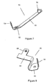
Figure 7 is a schematic perspective view of a spring contact of the electric connector; and -
Figure 8 is a schematic perspective view of a ground plate of the electric connector. - Now some preferred embodiments of the disclosure will be described with reference to the drawings.
- The disclosure generally relates to a gear cover assembly for an electric driver, especially used in a wiper system of a vehicle. Thus, a wiper motor assembly for a vehicle wiper system will described as an example, but it is appreciated that the disclosure is also applicable in other fields.
- The wiper motor assembly comprises an electric motor and a gear mechanism integrated with the electric motor for converting the high speed and low torque output of the an electric motor into a low speed and high torque output which is used to drive a wiper system linkage. The gear mechanism comprises at least an input gear, for example, a worm, and an output gear, for example, a worm gear. The output gear may mesh with the input gear directly, or indirectly via one or more intermediate gears when necessary.
- The gear mechanism is accommodated in a gear housing which is coupled to or formed integrally with a housing part of the electric motor. The gear housing is opened on one side for mounting and removing the gear mechanism. The output gear has a first side that faces outwards through the open side of the gear housing and a second opposite side which faces away from the open side. The output gear is formed with an output shaft which extends perpendicularly from the second side and passes through the gear housing for driving the wiper system linkage. A conductive contact plate of a parking system of the wiper system is carried by the first side of the output gear. The parking system of the wiper system is known in the art for moving the wiper blades back to their parking or home positions after a wiping operation of the wiper system is ended.
- The open side of the gear housing is closed by a gear cover assembly according to a preferred embodiment of the disclosure. As shown in
Figures 1 and 2 , the gear cover assembly mainly comprises agear cover 1 to be assembled to the gear housing and anelectric connector 2 carried by thegear cover 1. - According to a basic concept of the disclosure, the
gear cover 1 is made of a stamped sheet metal. As can be seen fromFigures 1 to 4 , thegear cover 1 has a flatcentral body 4 with acutout 6 which is inserted through by theelectric connector 2 to mount theelectric connector 2 to thegear cover 1. The outer periphery of thecentral body 4 is surrounded by a first orinner slot 8 which is delimited by a firstvertical wall 10 extending downwards from the outer periphery of thecentral body 4, abottom wall 12 extending outwards from the bottom edge of the outer periphery of thecentral body 4, and a secondvertical wall 14 extending upwards from the outer edge of thebottom wall 12. Theinner slot 8 is preferably continuous, but it may be alternatively not continuous. A second orouter slot 16 is formed surrounding thefirst slot 8 and delimited by the secondvertical wall 14, atop wall 18 extending outwards from the upper edge of the secondvertical wall 14, and a thirdvertical wall 20 extending downwards from the outer edge of thetop wall 18. Theouter slot 16 is preferably continuous, but it may be alternatively not continuous. - The first, second and third
vertical walls bottom wall 12. The second and thirdvertical walls vertical wall 10. In the state that thegear cover 1 is assembled to the gear housing, thefirst slot 8 faces away from the gear housing while thesecond slot 16 faces towards the gear housing. The upper edge of the gear housing along its open side is inserted into thesecond slot 16. A sealing member may be disposed in thesecond slot 16 to form a tight seal between the gear housing and thegear cover 1. - Along the lower edge of the third
vertical wall 20, there are formed with at least two (three in the illustrated embodiment)locking tabs 22 for locking thegear cover 1 to the gear housing. For example, eachlocking tab 22 is formed with a cut-throughhole 24 into which a corresponding locking protrusion on the gear housing is to be engaged. Thelocking tabs 22 are disposed with intervals therebetween along the lower edge of thesecond slot 16, and extend downwards, substantially perpendicular to thecentral body 4. For facilitating the engagement of the protrusions into the cut-throughholes 24, eachlocking tab 22 may be offset outwards from the thirdvertical wall 20 by a small distance, and is flexible outwards. - Further, several locating
tabs 26 are formed along the lower edge of the thirdvertical wall 20 for facilitating the locating of thegear cover 1 with respect to the gear housing. - Further, locating
holes 28 are formed through thegear cover 1 along the periphery of thecutout 6 for facilitating the locating of theelectric connector 2 with respect to thegear cover 1, as described later. - As can be seen from
Figures 1 and 2 , and with reference toFigures 5 and 6 , theelectric connector 2 comprises an insulativemain body 30 and a portion of a parking electric circuit of a parking system of the wiper system carried by themain body 30. Themain body 30 is formed of a plastic material by injection molding, and comprises abase portion 32 and anupper portion 34 formed on thebase portion 32. Theupper portion 34 is inserted through thecutout 6 of thegear cover 1 to be exposed outside. Theupper portion 34 and thecutout 6 have shapes complementary with each other. - Locating pins 36 are formed on the upper surface of the
base portion 32 at locations corresponding to the locating holes 28 of thegear cover 1. When theupper portion 34 is inserted through thecutout 6, the locating pins 36 are inserted through the locating holes 28 respectively for locating theelectric connector 2 to thegear cover 1 precisely. The locating pins 36 may have fixing structures (not shown). For example, each locatingpin 36 may be provided with a barb, a hook or the like for fixing theelectric connector 2 to thegear cover 1. Alternatively, a portion of the locatingpin 36 which is inserted into the locatinghole 28 may be deformed by melting so as to be riveted thereto. - A
continuous groove 38 is formed on the upper surface of thebase portion 32, surrounding theupper portion 34 and the locating pins 36. A sealing member (not shown) is partially received in thegroove 38 and is compressed between thebase portion 32 and the lower surface of thecentral body 4 to seal the interface between theupper portion 34 and thecentral body 4 around thecutout 6 and the locating holes 28. -
Outer terminals 40 of the parking electric circuit portion are exposed on the upper surface of theupper portion 34. - As shown in
Figure 2 , the parking electric circuit portion carried by themain body 30 comprises threespring contacts 50, i.e., an anode contact, a cathode contact and a ground contact, which contact the conductive contact plate on the output gear for detecting the operation state of the output gear, by means of which, the parking state of the wiper system is determined. Information about the parking state can be used for the controlling of the parking action of the wiper system. - As shown in
Figure 7 , eachspring contact 50 comprises a fixingportion 52 which is to be fixed to the bottom surface of thebase plate 32, an back contactingportion 54 which extends vertically from the back side of the fixingportion 52 and is electrically connected with the anode or cathode of a power supply or a ground, aflexible arm portion 56 which extends obliquely from the front side of the fixingportion 52, and acontact bump 58 formed on the tip end of thearm portion 56 for contacting with the conductive contact plate. - As also shown in
Figure 2 , the parking electric circuit portion further comprises aground plate 60 and two capacitors (condensers) 70. As shown inFigure 8 , theground plate 60 comprises a first fixingportion 62 which is to be fixed to the bottom surface of thebase plate 32, a first contactingportion 64 extending from one side of the first fixingportion 62, for electrically connecting with theback contacting portion 54 of theground spring contact 50, a second contactingportion 66 extending from another side of the first fixingportion 62, for electrically connecting with an leg of eachcapacitor 70, and asecond fixing portion 68 which is to be fixed to thegear cover 1, in particular to thebottom wall 12 of thefirst slot 8. In this way, thegear cover 1 acts as a ground part of the parking electric circuit portion. - The
capacitors 70 can be protected by ashrinkable sleeve 72. - The
electric connector 2 can be fixed to thegear cover 1 by the locating pins 36 with locking features, and/or by separate fasteners. - The
gear cover 1 is formed by stamping a sheet metal. Specifically, in a manufacturing process of thegear cover 1, a flat sheet metal is punched for forming thecutout 6, the locating holes 28, thelocking tab 22 with cut-throughholes 24, the locating tabs 26 (if any), and the like. Now thelocking tab 22 and the locatingtabs 26 are still substantially coplanar with thecentral body 4. - Further, by drawing and bending, the first and
second slots locking tab 22 and the locatingtabs 26 are formed. - The
gear cover 1 formed in this way has higher rigidity and strength than the plastic gear cover used in the prior art. Meanwhile, the sealingability of the internal space defined by the gear cover and the gear housing is increased. - In addition, the
gear cover 1 itself may act as a ground part of the parking system. - The disclosure also relates to an electric driver comprising an electric motor, a gear mechanism for outputting the motion of the electric motor, and a gear cover assembly described above which covers the gear mechanism, the electric connector forming a part of the parking electric circuit of the electric motor.
- The electric driver and its gear cover assembly of the disclosure provide an advantageous option to the art.
- While certain embodiments have been described, these embodiments are presented by way of example only, and are not intended to limit the scope of the disclosure. The scope and spirit of the disclosure are intended to cover all the modifications, substitutions and changes that can be made by those skilled in the art.
Claims (10)
- A gear cover assembly for covering a gear mechanism of an electric driver, comprising:a metal gear cover which is formed with a cutout therethrough; andan electric connector comprising an insulative main body and a conductive terminal carried by the insulative main body, the insulative main body being fixed to the gear cover, and the electric connector covering or extending through the cutout.
- The gear cover assembly of claim 1, wherein the gear cover is formed by pressing and comprises a flat central body and locking tabs which cooperate with corresponding locking structures on a gear housing to lock the gear cover to the gear housing.
- The gear cover assembly of claim 2, wherein the gear cover further comprises an outer slot surrounding the central body, the locking tabs extending from an outer vertical wall, which delimits the outer slot, towards the gear housing.
- The gear cover assembly of claim 3, wherein the gear cover further comprises locating tabs extending from the outer vertical wall for locating the gear cover with respect to the gear housing, and each locking tab comprises a cut-through hole into which a corresponding locking structure in the form of a locking protrusion on the gear housing is to be engaged.
- The gear cover assembly of claim 3, wherein the gear cover further comprises an inner slot between the central body and the outer slot, the inner slot facing away from the gear housing.
- The gear cover assembly of claim 2, wherein the central body is formed with locating holes around the periphery of the cutout, and the insulative main body of the electric connector is formed with locating pins which are inserted through the locating holes respectively for locating the electric connector to the gear cover.
- The gear cover assembly of claim 6, wherein the locating pins are formed with fixing features for fixing the electric connector to the gear cover.
- The gear cover assembly of claim 6, further comprising a sealing member sealing between the gear cover and the insulative main body of the electric connector around the cutout and the locating holes.
- The gear cover assembly of any one of claims 1 to 8, wherein the electric connector comprises a ground plate electrically connected to the gear cover.
- An electric driver, comprising:an electric motor;a gear mechanism for outputting the motion of the electric motor; anda gear cover assembly of any one of claims 1 to 9 which covers the gear mechanism, the electric connector forming a part of a parking electric circuit for the electric motor.
Applications Claiming Priority (1)
| Application Number | Priority Date | Filing Date | Title |
|---|---|---|---|
| CN201320486955.3U CN203413100U (en) | 2013-08-09 | 2013-08-09 | Electric driver and gear cover component thereof |
Publications (2)
| Publication Number | Publication Date |
|---|---|
| EP2835289A2 true EP2835289A2 (en) | 2015-02-11 |
| EP2835289A3 EP2835289A3 (en) | 2015-09-02 |
Family
ID=49975989
Family Applications (1)
| Application Number | Title | Priority Date | Filing Date |
|---|---|---|---|
| EP14168636.0A Withdrawn EP2835289A3 (en) | 2013-08-09 | 2014-05-16 | Electric driver and gear cover assembly thereof |
Country Status (2)
| Country | Link |
|---|---|
| EP (1) | EP2835289A3 (en) |
| CN (1) | CN203413100U (en) |
Families Citing this family (1)
| Publication number | Priority date | Publication date | Assignee | Title |
|---|---|---|---|---|
| JP6904765B2 (en) * | 2017-04-18 | 2021-07-21 | 日本電産サンキョー株式会社 | Fixed structure of cover and geared motor |
Family Cites Families (5)
| Publication number | Priority date | Publication date | Assignee | Title |
|---|---|---|---|---|
| US4792307A (en) * | 1986-11-14 | 1988-12-20 | United Technologies Electro Systems, Inc. | Electrical contact and terminal assembly |
| DE4101368C2 (en) * | 1991-01-18 | 2000-04-06 | Teves Gmbh Alfred | Electric motor and process for its manufacture |
| FR2750812B1 (en) * | 1996-07-08 | 1999-04-02 | Valeo Systemes Dessuyage | GEAR GEAR WITH BLADE HOLDER PLATE |
| DE102004027504A1 (en) * | 2004-06-04 | 2005-12-22 | Robert Bosch Gmbh | Cover for a transmission housing of a windshield wiper system |
| DE102010064151A1 (en) * | 2010-12-27 | 2012-06-28 | Robert Bosch Gmbh | Wiper motor comprises gear housing, in which driven shaft drivable by drive wheel is rotatably supported, where contact element is fastened at drive wheel for short circuit of two short circuit elements |
-
2013
- 2013-08-09 CN CN201320486955.3U patent/CN203413100U/en not_active Expired - Lifetime
-
2014
- 2014-05-16 EP EP14168636.0A patent/EP2835289A3/en not_active Withdrawn
Non-Patent Citations (1)
| Title |
|---|
| None |
Also Published As
| Publication number | Publication date |
|---|---|
| CN203413100U (en) | 2014-01-29 |
| EP2835289A3 (en) | 2015-09-02 |
Similar Documents
| Publication | Publication Date | Title |
|---|---|---|
| CN104488175B (en) | Adjust driver | |
| CN112310730B (en) | Connector with a locking member | |
| EP1962383A2 (en) | Electrical connector and combination connector having the same | |
| DE102013215949A1 (en) | An electronic module comprising an electric motor, preferably an electrically commutated motor | |
| JPH05505510A (en) | Electric motor and its manufacturing method | |
| HUP0200813A2 (en) | Motor housing and pole-well, in particular for electric window or sunroof motors | |
| CN105375139A (en) | Electronic structure unit, in particular capacitive proximity sensor | |
| TW201330419A (en) | Control device for automobile appliance plug housing | |
| US8344275B2 (en) | Switching device | |
| US10658782B2 (en) | Stop spring for a contact device, electrical contact de-vice assembly as well as electrical connector | |
| WO2018051718A1 (en) | Inverter-integrated electric compressor and method for manufacturing same | |
| US9735529B2 (en) | Plug-in module for a motor unit | |
| CN103891107B (en) | Servo-driver | |
| JP2010212136A (en) | Joint connector | |
| JP4851243B2 (en) | Joint connector with built-in capacitor | |
| CN102792524A (en) | Contact plug, drive unit containing same and production method for a drive unit | |
| JP2008016364A (en) | Shield structure, connector assembly and connector structure having shield structure, and casing assembly, and motor-driven compressor | |
| CN114051469B (en) | Wiper motor and method for manufacturing the same | |
| US11217926B2 (en) | Contact element having a contact body and a spring element arranged thereon | |
| JP2006085960A (en) | Multi-pole connector and its manufacturing method | |
| CN203413100U (en) | Electric driver and gear cover component thereof | |
| JP6203814B2 (en) | Windscreen wiper motor and suppression assembly for windscreen wiper motor | |
| CN103733483A (en) | Carbon brush earth circuit | |
| US10932377B2 (en) | Housing for electrical components and method for connecting a housing body to a housing cover | |
| CN201252193Y (en) | Electric connector |
Legal Events
| Date | Code | Title | Description |
|---|---|---|---|
| PUAI | Public reference made under article 153(3) epc to a published international application that has entered the european phase |
Free format text: ORIGINAL CODE: 0009012 |
|
| 17P | Request for examination filed |
Effective date: 20140516 |
|
| AK | Designated contracting states |
Kind code of ref document: A2 Designated state(s): AL AT BE BG CH CY CZ DE DK EE ES FI FR GB GR HR HU IE IS IT LI LT LU LV MC MK MT NL NO PL PT RO RS SE SI SK SM TR |
|
| AX | Request for extension of the european patent |
Extension state: BA ME |
|
| PUAL | Search report despatched |
Free format text: ORIGINAL CODE: 0009013 |
|
| AK | Designated contracting states |
Kind code of ref document: A3 Designated state(s): AL AT BE BG CH CY CZ DE DK EE ES FI FR GB GR HR HU IE IS IT LI LT LU LV MC MK MT NL NO PL PT RO RS SE SI SK SM TR |
|
| AX | Request for extension of the european patent |
Extension state: BA ME |
|
| RIC1 | Information provided on ipc code assigned before grant |
Ipc: B60S 1/16 20060101ALI20150727BHEP Ipc: H02K 7/116 20060101ALI20150727BHEP Ipc: B60S 1/08 20060101AFI20150727BHEP Ipc: F16H 57/031 20120101ALI20150727BHEP Ipc: H02K 5/22 20060101ALI20150727BHEP |
|
| STAA | Information on the status of an ep patent application or granted ep patent |
Free format text: STATUS: THE APPLICATION IS DEEMED TO BE WITHDRAWN |
|
| 18D | Application deemed to be withdrawn |
Effective date: 20160303 |