EP2835263A2 - Dot recording apparatus, dot recording method, and computer program therefor - Google Patents
Dot recording apparatus, dot recording method, and computer program therefor Download PDFInfo
- Publication number
- EP2835263A2 EP2835263A2 EP14176799.6A EP14176799A EP2835263A2 EP 2835263 A2 EP2835263 A2 EP 2835263A2 EP 14176799 A EP14176799 A EP 14176799A EP 2835263 A2 EP2835263 A2 EP 2835263A2
- Authority
- EP
- European Patent Office
- Prior art keywords
- main scan
- recording
- dot
- scan direction
- mask
- Prior art date
- Legal status (The legal status is an assumption and is not a legal conclusion. Google has not performed a legal analysis and makes no representation as to the accuracy of the status listed.)
- Granted
Links
- 238000000034 method Methods 0.000 title claims description 6
- 238000004590 computer program Methods 0.000 title description 6
- 230000007246 mechanism Effects 0.000 claims description 6
- 239000000976 ink Substances 0.000 description 51
- 239000007788 liquid Substances 0.000 description 28
- 238000010586 diagram Methods 0.000 description 27
- 230000004048 modification Effects 0.000 description 18
- 238000012986 modification Methods 0.000 description 18
- 230000000295 complement effect Effects 0.000 description 15
- 230000008859 change Effects 0.000 description 6
- 239000000463 material Substances 0.000 description 6
- 230000008901 benefit Effects 0.000 description 5
- 230000000694 effects Effects 0.000 description 3
- 230000006870 function Effects 0.000 description 3
- 239000011347 resin Substances 0.000 description 3
- 229920005989 resin Polymers 0.000 description 3
- 239000000758 substrate Substances 0.000 description 3
- 238000006243 chemical reaction Methods 0.000 description 2
- 239000003086 colorant Substances 0.000 description 2
- 239000004973 liquid crystal related substance Substances 0.000 description 2
- 238000004519 manufacturing process Methods 0.000 description 2
- 239000002184 metal Substances 0.000 description 2
- 230000003287 optical effect Effects 0.000 description 2
- 230000001629 suppression Effects 0.000 description 2
- XLYOFNOQVPJJNP-UHFFFAOYSA-N water Substances O XLYOFNOQVPJJNP-UHFFFAOYSA-N 0.000 description 2
- 238000000018 DNA microarray Methods 0.000 description 1
- 239000002253 acid Substances 0.000 description 1
- 239000003513 alkali Substances 0.000 description 1
- 230000002457 bidirectional effect Effects 0.000 description 1
- 230000005540 biological transmission Effects 0.000 description 1
- 238000004891 communication Methods 0.000 description 1
- 230000006866 deterioration Effects 0.000 description 1
- 239000007772 electrode material Substances 0.000 description 1
- 238000005401 electroluminescence Methods 0.000 description 1
- 238000005530 etching Methods 0.000 description 1
- 239000012943 hotmelt Substances 0.000 description 1
- 229910001867 inorganic solvent Inorganic materials 0.000 description 1
- 239000003049 inorganic solvent Substances 0.000 description 1
- 239000007791 liquid phase Substances 0.000 description 1
- 239000010687 lubricating oil Substances 0.000 description 1
- 239000008204 material by function Substances 0.000 description 1
- 239000002923 metal particle Substances 0.000 description 1
- 239000000203 mixture Substances 0.000 description 1
- 239000003921 oil Substances 0.000 description 1
- 239000011368 organic material Substances 0.000 description 1
- 239000003960 organic solvent Substances 0.000 description 1
- 239000002245 particle Substances 0.000 description 1
- 239000000049 pigment Substances 0.000 description 1
- 238000001454 recorded image Methods 0.000 description 1
- 239000011343 solid material Substances 0.000 description 1
- 239000002904 solvent Substances 0.000 description 1
- 239000004753 textile Substances 0.000 description 1
Images


Classifications
-
- B—PERFORMING OPERATIONS; TRANSPORTING
- B41—PRINTING; LINING MACHINES; TYPEWRITERS; STAMPS
- B41J—TYPEWRITERS; SELECTIVE PRINTING MECHANISMS, i.e. MECHANISMS PRINTING OTHERWISE THAN FROM A FORME; CORRECTION OF TYPOGRAPHICAL ERRORS
- B41J2/00—Typewriters or selective printing mechanisms characterised by the printing or marking process for which they are designed
- B41J2/005—Typewriters or selective printing mechanisms characterised by the printing or marking process for which they are designed characterised by bringing liquid or particles selectively into contact with a printing material
- B41J2/01—Ink jet
- B41J2/015—Ink jet characterised by the jet generation process
- B41J2/04—Ink jet characterised by the jet generation process generating single droplets or particles on demand
- B41J2/045—Ink jet characterised by the jet generation process generating single droplets or particles on demand by pressure, e.g. electromechanical transducers
- B41J2/04501—Control methods or devices therefor, e.g. driver circuits, control circuits
- B41J2/04595—Dot-size modulation by changing the number of drops per dot
-
- B—PERFORMING OPERATIONS; TRANSPORTING
- B41—PRINTING; LINING MACHINES; TYPEWRITERS; STAMPS
- B41J—TYPEWRITERS; SELECTIVE PRINTING MECHANISMS, i.e. MECHANISMS PRINTING OTHERWISE THAN FROM A FORME; CORRECTION OF TYPOGRAPHICAL ERRORS
- B41J2/00—Typewriters or selective printing mechanisms characterised by the printing or marking process for which they are designed
- B41J2/005—Typewriters or selective printing mechanisms characterised by the printing or marking process for which they are designed characterised by bringing liquid or particles selectively into contact with a printing material
- B41J2/01—Ink jet
- B41J2/205—Ink jet for printing a discrete number of tones
- B41J2/2054—Ink jet for printing a discrete number of tones by the variation of dot disposition or characteristics, e.g. dot number density, dot shape
-
- B—PERFORMING OPERATIONS; TRANSPORTING
- B41—PRINTING; LINING MACHINES; TYPEWRITERS; STAMPS
- B41J—TYPEWRITERS; SELECTIVE PRINTING MECHANISMS, i.e. MECHANISMS PRINTING OTHERWISE THAN FROM A FORME; CORRECTION OF TYPOGRAPHICAL ERRORS
- B41J2/00—Typewriters or selective printing mechanisms characterised by the printing or marking process for which they are designed
- B41J2/005—Typewriters or selective printing mechanisms characterised by the printing or marking process for which they are designed characterised by bringing liquid or particles selectively into contact with a printing material
- B41J2/01—Ink jet
- B41J2/205—Ink jet for printing a discrete number of tones
- B41J2/2056—Ink jet for printing a discrete number of tones by ink density change
-
- B—PERFORMING OPERATIONS; TRANSPORTING
- B41—PRINTING; LINING MACHINES; TYPEWRITERS; STAMPS
- B41J—TYPEWRITERS; SELECTIVE PRINTING MECHANISMS, i.e. MECHANISMS PRINTING OTHERWISE THAN FROM A FORME; CORRECTION OF TYPOGRAPHICAL ERRORS
- B41J2/00—Typewriters or selective printing mechanisms characterised by the printing or marking process for which they are designed
- B41J2/005—Typewriters or selective printing mechanisms characterised by the printing or marking process for which they are designed characterised by bringing liquid or particles selectively into contact with a printing material
- B41J2/01—Ink jet
- B41J2/21—Ink jet for multi-colour printing
- B41J2/2132—Print quality control characterised by dot disposition, e.g. for reducing white stripes or banding
Definitions
- the present invention relates to a dot recording apparatus, a dot recording method, and a computer program therefor.
- a printing apparatus which functions as a dot recording apparatus and which forwardly and backwardly moves a plurality of recording heads which eject inks of different colors with respect to recording materials, performs a main scan at the time of a forward movement and a backward movement, and thereby performs printing (for example, JP-A-6-22106 ).
- pixel groups configured by mxn pixels are arranged so as not to be adjacent to each other, within an area where printing can be performed by one time of a main scan.
- a plurality of main scans is performed using a plurality of thinning patterns which are in a mutually complementary arrangement relationship and thereby the recording is completed.
- each pixel group has a rectangular shape. Since a boundary between the pixel groups is configured with a side in parallel with a main scan direction and a side in parallel with a sub-scan direction, a long boundary extending in the main scan direction and a long boundary extending in the sub-scan direction are formed by a set of the boundaries of the pixel groups adjacent to each other. For this reason, there is a problem that banding (image quality deterioration area) along such long boundaries easily occurs and stands out. In addition, in the printing apparatus which performs the main scan and forms dots, there is a problem that the banding of the main scan direction easily stands out.
- the invention can be realized by various forms such as a recording method, a computer program, and a recording medium in which the computer program is stored, in addition to the dot recording apparatus.
- Fig. 1 is an explanatory diagram illustrating a configuration of a dot recording system.
- the dot recording system 10 includes an image processing unit 20 and a dot recording unit 60.
- the image processing unit 20 generates print data for the dot recording unit 60 from image data (for example, image RGB data).
- the image processing unit includes a CPU 40 (referred to as "control unit 40"), a ROM 51, a RAM 52, an EEPROM 53, and an output interface 45.
- the CPU 40 has functions of a color conversion processing portion 42, a halftone processing portion 43, and a rasterizer 44. Such functions are realized by a computer program.
- the color conversion processing portion 42 converts multiple gradation RGB data of an image into ink amount data which represents an amount of ink of a plurality of colors.
- the halftone processing portion 43 generates dot data illustrating a dot forming state for each pixel, by performing halftone processing with respect to the ink amount data.
- the rasterizer 44 rearranges the dot data generated by the halftone processing into the dot data which is used in each main scan performed by the dot recording unit 60.
- An operation of dot recording which is explained in the following various embodiments is a rasterizing operation (that is, an operation which is represented by raster data) which is realized by the rasterizer 44.
- the dot recording unit 60 is, for example, a serial type ink jet recording apparatus, and includes a control unit 61, a carriage motor 70, a driving belt 71, a pulley 72, a sliding shaft 73, a paper feeding motor 74, a paper feeding roller 75, a carriage 80, ink cartridges 82 to 87, and a recording head 90.
- the driving belt 71 is stretched between the carriage motor 70 and the pulley 72.
- the driving belt 71 is attached to the carriage 80.
- the ink cartridges 82 to 87 which respectively contain, for example, cyan ink (C), magenta ink (M), yellow ink (Y), black ink (K), light cyan ink (Lc), and light magenta ink (Lm) are provided.
- various inks other than these inks can be used as the ink.
- nozzle rows corresponding to the above-described various color inks are formed. If such ink cartridges 82 to 87 are mounted on the carriage 80 from above, the ink can be supplied from each cartridge to the recording head 90.
- the sliding shaft 73 is arranged in parallel with the driving belt, and penetrates the carriage 80.
- the carriage motor 70 drives the driving belt 71
- the carriage 80 moves along the sliding shaft 73.
- This direction is referred to as a "main scan direction”.
- the carriage motor 70, the driving belt 71, and the sliding shaft 73 configure a main scan driving mechanism.
- the ink cartridges 82 to 87 and the recording head 90 also move in the main scan direction.
- the ink is ejected from the nozzles (described later) arranged in the recording head 90 to the recording medium P (typically, printing paper), and thereby dot recording is performed on the recording medium P.
- the movement in the main scan direction of the recording head 90 and ejecting of the ink are referred to as a main scan, and one time of main scan is referred to as a "main scan pass" or merely as a "pass".
- the paper feeding roller 75 is connected to the paper feeding motor 74. During recording, the recording medium P is inserted onto the paper feeding roller 75. If the carriage 80 moves to an end portion in the main scan direction, the control unit 61 rotates the paper feeding motor 74. As a result, the paper feeding roller 75 also rotates, and moves the recording medium P.
- a relative movement between the recording medium P and the recording head 90 is referred to as a sub-scan, and a relative movement direction is referred to as a "sub-scan direction”.
- the paper feeding motor 74 and the paper feeding roller 75 configure a sub-scan driving mechanism.
- the sub-scan direction is a direction (orthogonal direction) which is perpendicular to the main scan direction.
- the sub-scan direction is not required to be always orthogonal to the main scan direction, and may intersect.
- a main scan operation and a sub-scan operation are alternately performed.
- a dot recording operation it is possible to perform at least one of a unidirectional recording operation which performs the dot recording by only the main scan of a forward path, and a bidirectional recording operation which performs the dot recording by the main scans of both directions of the forward path and a backward path.
- the direction of the main scan is merely reversed, and thus, hereinafter, the forward path and the backward path will be described without being distinguished as long as there is no particular necessity.
- the image processing unit 20 may be configured integrally with the dot recording unit 60.
- the image processing unit 20 may be configured separately from the dot recording unit 60 by being built in a computer (not illustrated).
- the image processing unit 20 may be implemented by the CPU as printer driver software (computer program) stored in the computer.
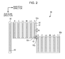
- Fig. 2 is an explanatory diagram illustrating an example of a configuration of a nozzle row of the recording head 90.
- two recording heads 90 are illustrated.
- the recording head 90 may be one piece and may be two or more.
- the two recording heads 90a and 90b respectively include nozzle rows 91 for each color.
- Each nozzle row 91 includes a plurality of nozzles 92 which are lined up in the sub-scan direction at a constant nozzle pitch dp.
- a nozzle 92x of an end portion of the nozzle row 91 of the first recording head 90a is shifted in the sub-scan direction by the same distance as the nozzle pitch dp of the nozzle row 91, from a nozzle 92y of an end portion of the nozzle row 91 of the second recording head 90b.
- the (combined) nozzle row for one color, of the two recording heads 90a and 90b has the same value as a nozzle row 95 (illustrated on a left-hand side of Fig. 2 ) which has two times the number of nozzles for one color of one recording head 90.
- the nozzle row may also be a combined nozzle row for example formed by two or more recording heads.
- the nozzle pitch dp and a pixel pitch on the recording medium P are the same as each other.
- the nozzle pitch dp can also be a multiple of the pixel pitch on the recording medium P.
- interlacing recording an operation of performing an operation of recording the dots by a pass after the second pass, in such a manner that a dot gap between the main scan lines recorded in the first pass is filled
- the nozzle pitch dp is a value (0.035 mm) corresponding to, for example, 720 dpi.
- Fig. 3 is an explanatory diagram illustrating both a position of a nozzle row 95 of two main scan passes of dot recording and a recording area at the positions, according to a first embodiment.
- ink for example, cyan ink
- a dot recording operation which completes forming of the dots on each main scan line by N (N is an integer equal to or greater than two) main scan passes is referred to as "multi-pass recording”.
- N which is the number of passes of multi-pass recording is 2.
- the position of the nozzle row 95 is shifted in the sub-scan direction by a distance corresponding to half of a head height Hh.
- the head height Hh means a distance which is represented by Mxdp (M is the number of nozzles of the nozzle row 95 and dp is the nozzle pitch).
- the dot recording is performed in 50% of all pixels in an area Q1 which is configured with the main scan lines through which the nozzles of an upper half of the nozzle row 95 penetrate, and in 50% of all pixels in an area Q2 which is configured with main scan lines through which the nozzles of a lower half of the nozzle row 95 penetrate, in the recording medium P.
- the dot recording is performed in the remaining 50% of the pixels where the dots are not formed in the first pass of all the pixels of the area Q2 which is configured with the main scan lines through which the nozzles of the upper half of the nozzle row 95 penetrate, and in 50% of all pixels in an area Q3 which is configured with main scan lines through which the nozzles of the lower half of the nozzle row 95 penetrate, in the recording medium P.
- 50% of the area Q2 is recorded, respectively, by each of the first and second passes, and the recording of a total of 100% of the pixels is performed.
- the dot recording is performed in the remaining 50% of the pixels of the area Q3, and in the pixels of 50% of the area Q4 (not illustrated) next thereto.
- the image (beta image) in which dots are formed on all the pixels of the recording medium P is formed on the recording medium P, but the recorded image (printed image) which is represented by actual dot data includes the pixels which actually form dots in the recording medium P and the dots which are not actually formed in the recording medium P. That is, whether or not the dots on each pixel of the recording medium P are actually formed is determined by the dot data which is generated by the halftone processing.
- the term “dot recording” means “dot is formed or not formed”.
- the term “dot recording is performed” is used as a term which means “it is responsible for dot recording", regardless of whether or not the dots on the recording medium P are actually formed.
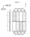
- Fig. 4 is an explanatory diagram illustrating a mask for forming a dot recording pattern in each pass
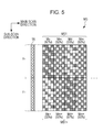
- Fig. 5 is an explanatory diagram illustrating a specified example of the mask in Fig. 4
- the mask MS is configured with a first mask MS1 which is assigned with respect to the nozzle group X of the upper half of the nozzle row 95, and a second mask MS1* which is assigned with respect to the nozzle group Y of the lower half of the nozzle row 95.
- the mask MS is repeatedly arranged along the main scan direction on the recording medium P.
- the first mask MS1 is configured by four mask areas Mu, Mm, Md and Mm of rectangular shape which are sequentially separated in each section with a constant length of an amount of a plurality of dots lined up in the main scan direction.
- the first mask area Mu is an area in which the nozzle group X of the upper half has a dot rate (67% in the present example), which represents a rate responsible for the dot recording, more than 50%, within the area.
- the third mask area Md is an area in which the dot rate (33% in the present example) of the nozzle group X of the upper half is less than 50%, within the area.
- the dot rate of the first mask area Mu and the dot rate of the third mask area Md are set in such a manner that the average of the dot rates is 50%.
- the second and fourth mask areas Mm are areas in which the dot rate of each nozzle of the upper head X in the area is 50%.
- the dot rate in the area of the first mask MS1 becomes an average of 50%.
- the first mask MS1 is repeatedly arranged in the main scan direction, and thereby the dot rate of each area lined up in the main scan direction is changed gradually and periodically.
- the dot rate of each of the four areas is not limited thereto, and the dot rate of each area is changed gradually and periodically, and an average of the dot rate may be set so as to be 50%.
- the first mask area Mu for example, as illustrated in Fig. 5 , is set as one area which is divided into 4x12 pixels, and is configured by setting two thirds of all the pixels in the area as the pixels (hereinafter, referred to as "responsible pixel") responsible for the dot recording, and by setting the remaining third (the rest of) the pixels as the pixels (hereinafter, referred to as "non-responsible pixel") not responsible for the dot recording.
- the third mask area Md for example, as illustrated in Fig. 5 , is also configured by setting a third of all the pixels in the area as responsible pixels, and by setting the other two thirds (the rest of) the pixels as non-responsible pixels.
- the second and fourth mask areas Mm are configured by setting a half of all the pixels in the area as responsible pixels, and by setting the other half of (the rest of) the pixels as non-responsible pixels.
- the responsible pixels and the non-responsible pixels be set so as to be respectively distributed without deviation, in the area.
- the arrangement position of the responsible pixels and the non-responsible pixels is not necessarily the same and can be set at random.
- the second mask MS1* is configured by four mask areas Mu*, Mm*, Md* and Mm* which are sequentially separated along the main scan direction so as to coincide with a boundary along the sub-scan direction of each mask area of the first mask MS1.
- a fifth mask area Mu* is an area with a rate (33% in the present example) which is set in such a manner that the dot rate of the nozzle group Y of the lower half in the area is brought into a complementary relationship with the first mask area Mu.
- the fifth mask area Mu* as illustrated in Fig.
- a seventh mask area Md* is an area with a rate (67% in the present example) which is set in such a manner that the dot rate of the nozzle group Y of the lower half in the area is brought into a complementary relationship with the third mask area Md.
- the seventh mask area Md* is set in such a manner that the non-responsible pixels in the third mask area Md become the responsible pixels and the responsible pixels become the non-responsible pixels.
- sixth and eighth mask areas Mm* are also areas with a rate (50% in the present example) which is set in such a manner that the dot rate of the nozzle group Y of the lower half in the area is brought into the complementary relationship with the second and fourth mask areas Mm.
- the sixth and eighth mask areas Mm* are set in such a manner that the non-responsible pixels in the second and fourth mask areas Mm become the responsible pixels and the responsible pixels become the non-responsible pixels.
- Fig. 6 is an explanatory diagram illustrating a state where dot recording is performed by a first pass 1P and a second pass 2P.
- the nozzle row 95 of the first pass illustrated in the left-hand side of Fig. 6 moves in the main scan direction, and thereby, in an area Q1 illustrated in the right-hand side of Fig. 6 , dot recording responding (corresponding) to the first mask MS1 ( Fig. 5 ) assigned in the nozzle group X1 of the upper half of the mask MS illustrated in Fig. 4 is performed.
- dot recording responding to the second mask MS1* ( Fig. 6 ) assigned in the nozzle group Y1 of a lower half of the mask MS is performed.
- the responsible pixels of the first pass 1P are illustrated by a circle with right diagonal upward hatched lines.
- the nozzle row 95 is shifted by an amount of half (12 pixels in the present example) of the head height Hh (24 pixels in the present example) in the sub-scan direction from the position of the first pass 1P, and then moves in the main scan direction.
- the area Q2 dot recording responding to the first mask MS1* assigned in the nozzle group X2 of the upper half of the mask MS is performed.
- area Q3 dot recording responding to the second mask MS1* assigned in the nozzle group Y2 of the lower half of the mask MS is performed.
- the responsible pixels of the second pass are illustrated by a circle with left diagonal upward hatched lines. As a result, the dot recording of all the pixels in the area Q2 is completed.
- the dot recording according to the mask MS is performed.
- moving the nozzle row 95 in the main scan direction and ejecting the ink, and relatively moving the recording medium P in the sub-scan direction are alternately repeated several times, and thereby the dot recording on the recording medium P is completed.
- a printing target area (recording target area) in which the image is actually printed (recorded) is at or lower than the area Q2. This is similarly applied to the other embodiments described later.
- the mask MS also moves as the nozzle row 95 moves in the sub-scan direction, but instead of this, the mask MS may be arranged repeatedly in a tiled form in the main scan direction and the sub-scan direction on the recording medium P, and thereby the responsible pixels may be determined.
- the pixel with the hatched lines in Fig. 5 is treated as indicating a pixel which performs the dot recording in the odd-numbered main scan passes, and the pixel without the hatched lines is treated as indicating a pixel which performs the dot recording in the even-numbered main scan passes.
- the dot recording operation described using Figs. 3 to 6 is realized by a rasterizing operation performed by the rasterizer 44. That is, the dot recording operation is independent of the actual printing target image, and is an operation of determining in which pass and by which nozzle the dot recording of each pixel on each main scan lines is performed. Whether or not the dot is actually formed at each pixel is determined according to the printing target image.
- the mask MS ( Figs. 3 and 4 ) used by the rasterizing operation is stored in a non-volatile memory device such as the ROM 51 or the EEPROM 53.
- the first mask MS1 and the second mask MS1* which configure the mask MS may be configured so as to be separately stored.
- the dot recording of each area is completed by the dot recording performed by the two passes.
- the mask MS which is used by the dot recording in each pass is set in such a manner that such a dot rate is changed repeatedly, gradually and periodically in an arrangement sequence of a plurality of sections separated by a section of a constant length of a plurality of pixels lined up in the main scan direction.
- the dot rate is changed gradually and periodically over the plurality of sections, and thus it is possible to suppress the banding along the main scan direction from occurring.
- the dot rate is changed gradually and periodically for each section, and thereby it is possible to suppress a rapid change of the dot rate for each section along the main scan direction, and thus it is possible to prevent the banding from easily standing out due to rapid change of dot rate occurring at the sections adjacent to each other.
- the mask since the mask is set in such a manner that all the nozzles do not eject the inks simultaneously, it is possible to suppress a concern that a landing position of the ink ejected by an airflow occurring according to the ink ejected from the nozzle is different from the assumed position, compared to a case where the inks are simultaneously ejected from all the nozzles.
- Fig. 7 is an explanatory diagram illustrating a first modification example of a mask for forming a dot recording pattern in each pass.
- the mask MS of Fig. 4 illustrates a configuration in which one piece of the first mask MS1 is arranged with respect to the nozzle group X of the upper half of the nozzle row 95, and one piece of the second mask MS1* is arranged with respect to the nozzle group Y of the lower half of the nozzle row 95.
- the filter 7 has a configuration in which a plurality of the first masks MS1 is arranged along a nozzle height direction (sub-scan direction) with respect to the nozzle group X of the upper half, and in the same manner, has a configuration in which a plurality of the second masks MS1* is arranged along the nozzle height direction, also with respect to the nozzle group Y of the lower half.
- the first mask MS1 and the second mask MS1* are separately stored one by one in the non-volatile memory device, and they are repeatedly used, and thereby the mask MSA illustrated in Fig. 7 may be configured so as to be realized. In this way, there is an advantage that an amount of mask data is reduced.
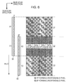
- FIG. 8 is an explanatory diagram illustrating a second modification example of the mask for forming the dot recording pattern in each pass.
- a mask MSB of Fig. 8 has a configuration in which the first mask MS1 and the second mask MS1*, as one pair, are arranged alternately and plurally in the sub-scan direction with respect to the nozzle group X of the upper half, and the second mask MS1* and the first mask MS1, as one pair, are arranged alternately and plurally in the sub-scan direction with respect to the nozzle group Y of the lower half.
- the mask MSB in the same manner as the mask MSA of Fig. 7 , there is an advantage that an amount of the mask data which is stored in the non-volatile memory device is reduced.
- Fig. 9 is an explanatory diagram illustrating a mask for forming a dot recording pattern in each pass, according to a second embodiment. Also in the second embodiment, N which is the number of passes of the multi-pass recording is 2.
- the mask areas in which dot rates different from each other are assigned are divided by boundaries in parallel with each other in the sub-scan direction.
- the mask areas in which dot rates different from each other are assigned are formed so as to have zigzag shapes.
- the boundaries of the mask areas of the mask MSC according to the second embodiment have zigzag shapes, or the mask MSC according to the second embodiment has areas formed in the zigzag shapes in such a manner that the rate at which the nozzle group that is responsible for the dot recording is changed in each predetermined range along a direction which intersects with the main scan direction and the sub-scan direction.
- the mask MSC is configured with a first mask MS1a corresponding to the nozzle group X of the upper half, and a second mask MS1a* corresponding to the nozzle group Y of the lower half.
- the second mask MS1a* has a complementary relationship with the first mask MS1a.
- the first mask MS1a in the same manner as the first mask MS1 ( Fig. 4 ) according to the first embodiment, is divided into four types of mask areas Mula, (dot rate is 67%), Mmla (dot rate is 50%), Mdla (dot rate is 33%), and Mmla (dot rate is 50%).
- a left and right boundary (that is, a boundary along the sub-scan direction) of each mask area has a linear shape with a tilt of 45 degrees with respect to the main scan direction and the sub-scan direction, and has a shape of mirror symmetry with respect to a center in the sub-scan direction.
- the second MS1a* has four mask areas Mu1a*, Mm1a*, Md1a*, and Mm1a* which have a complementary relationship with the four mask areas Mula, Mmla, Mdla, and Mmla of the first mask MS1a, and a left and right boundary of each mask area has a linear shape with a tilt of 45 degrees with respect to the main scan direction and the sub-scan direction, and has a shape of mirror symmetry with respect to the center in the sub-scan direction.
- the mask MSC according to the second embodiment is also set in such a manner that the dot rate for each section of a constant length of an amount of a plurality of pixels lined up in the main scan direction is changed repeatedly, gradually and periodically.
- the dot rate in a case where the dot recording is performed using the mask MSC, the main scan line is divided for each constant section, the dot rate is changed gradually and periodically over the plurality of sections, and thereby it is possible to suppress the banding along the main scan direction from occurring.
- the dot rate for each section is changed gradually and periodically, and thereby it is possible to suppress a rapid change of the dot rate for each section along the main scan direction, and thus it is possible to suppress the banding from easily standing out due to the rapid change of the dot rate at the sections adjacent to each other.
- the boundary of the mask area with the dot rates different from each other has a linear shape with a tilt of 45 degrees so as not to be a linear shape along the main scan direction and the sub-scan direction.
- division into a plurality of sections for each constant length can be done gradually and periodically, along not only the main scan direction but also the sub-scan direction. In this way, it is also possible to suppress the banding along the sub-scan direction from occurring.
- the mask is set in such a manner that all the nozzles do not perform the dot recording simultaneously, it is possible to suppress a concern that a landing position of the ink ejected by an airflow occurring according to the ink ejected from the nozzle is different from the assumed position, compared to a case where the inks are simultaneously ejected from all the nozzles.
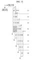
- Fig. 10 is an explanatory diagram illustrating both a position of the nozzle row 95 of four main scan passes and a recording area at the position, according to a third embodiment.
- the dot recording at the position of all the pixels on each main scan line is completed by two passes, but in the third embodiment, the dot recording at the position of all the pixels on each main scan line is completed by four passes. That is, in the third embodiment, N which is the number of passes of multi-pass recording is 4.
- the dot recording at the odd-numbered pixel positions in the main scan direction is performed, and in the third and fourth passes, the dot recording at the even-numbered pixel positions is performed.
- the recording medium P moves to a lower side in the sub-scan direction by a distance of a quarter of the head height Hh.
- the dot recording is performed in the pixels of 50% of the odd-numbered pixels in the first pass, and the dot recording is performed in the other 50% of the odd-numbered pixels in the second pass. Then, the dot recording is performed in the pixels of 50% of the even-numbered pixels in the third pass, and the dot recording is performed in the remaining 50% of the even-numbered pixels in the fourth pass.
- 50% (25% with respect to all pixels) of the odd-numbered pixels are recorded in the first and second passes, respectively, and the even-numbered pixels are recorded by 50% (by 25% with respect to all pixels) in the third and fourth passes, respectively, so that the recording in 100% of the pixels is performed.
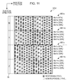
- Fig. 11 is an explanatory diagram illustrating a mask for forming a dot recording pattern in each pass.
- the mask MSD is configured with a first mask area MSle which is assigned with respect to a first nozzle group W from the top, a second mask area MS1*e which is assigned with respect to a second nozzle group X from the top, a third mask area MS1o which is assigned with respect to a third nozzle group Y from the top, and a fourth mask area MS1*o which is assigned with respect to a fourth nozzle group Z from the top, among the nozzles in which the nozzle height Hh of the nozzle row 95 is divided into four groups.
- the first mask area MSle and the second mask area MS1*e are masks which are in charge of the dot recording of the even-numbered pixels in the main scan direction, and positions of the dot recording in the even-numbered pixels have a complementary relationship with each other.
- the third mask area MS1o and the fourth mask area MS1*o are masks which are in charge of the dot recording of the odd-numbered pixels in the main scan direction, and positions of the dot recording in the odd-numbered pixels have a complementary relationship with each other.
- Figs. 12A to 12E are explanatory diagrams illustrating a state where dot recording is performed within area Q4 in the first to fourth passes.
- the first pass 1P as illustrated in Fig. 12A , according to the fourth mask MS1*o which is assigned to the fourth nozzle group Z1 from the top of the mask MSD illustrated in Fig. 11 , the dot recording of the odd-numbered pixels in the main scan direction is performed.
- the second pass 2P as illustrated in Fig. 12B
- the third mask MS1o which is assigned to the third nozzle group Y2 from the top of the mask MSD illustrated in Fig. 11
- the dot recording of the odd-numbered pixels in the main scan direction is performed.
- the dot recording of the pixels of the odd number row in the main scan direction of the area Q4 is completed.
- the responsible pixels formed in the first and second passes are illustrated by a circle with left diagonal upward hatched lines.
- the dot recording of the even-numbered pixels in the main scan direction is performed.
- the dot recording of the even-numbered pixels in the main scan direction is performed.
- the dot recording of the pixels of the even number row in the main scan direction of the area Q4 is completed.
- the responsible pixels formed in the third and fourth passes are illustrated by a circle with right diagonal upward hatched lines.
- the dot recording of all the pixels of the area Q4 is completed by four times of passes.
- the dot recording is performed by the third and fourth masks MS1o and MS1*o according to the odd number row in the main scan direction, and in the (4q+3)th and (4q+4)th passes, the dot recording is performed by the first and second masks MSle and MS1*e according to the even number row in the main scan direction. In this way, a main scan pass and a sub-scan pass are alternately and repeatedly performed several times, and thereby the dot recording on the recording medium P is completed.
- the third embodiment in the same manner as in the first embodiment, it is possible to suppress the banding along the main scan direction from occurring. Since the mask is set in such a manner that all the nozzles do not eject the inks simultaneously, it is possible to suppress a concern that a landing position of the ink ejected by an airflow occurring according to the ink ejected from the nozzle is different from the assumed position, compared to a case where the inks are simultaneously ejected from all the nozzles.
- the dot recording of each area is completed in four passes
- a case where the dot recording at the pixel positions of the odd number rows is performed in the first and second passes, and the dot recording at the pixel positions of the even number rows is performed in the third and fourth passes is described as an example, but it may be set in such a manner that the dot recording of the even number rows is performed in the first and second passes, and the dot recording at the pixel positions of the odd number rows is performed in the third and fourth passes.
- it may be set in such a manner that the dot recording at the pixel position of one of the even number row or the odd number row is performed in the first and third passes, and the dot recording at the pixel position of the other row is performed in the second and fourth passes.
- the arrangement of the responsible pixels in the two masks MSle and Ms1*e in the upper portion of Fig. 11 is the same as that in which the masks MS1 and MS1* illustrated in Fig. 5 are applied to only the pixel position of the even number row (that is, in which each pixel row of the masks MS1 and MS1* of Fig. 5 is used as the even numbered pixel rows, and the odd-numbered pixel rows are inserted therebetween).
- the two masks MS1o and MS1*o in the lower portion of Fig. 11 are the same as those in which the masks MS1 and MS1* illustrated in Fig. 5 are applied to only the pixel position of the odd number row.
- the mask MS of Fig. 5 is stored in the non-volatile memory device, and the applied pixel row of the mask MS is switched, and thereby it is possible to perform the rasterizing control according to the third embodiment. In this way, it is possible to reduce a memory capacity for the mask.
- Such a modification can also be applied to the other embodiments described in the following description.
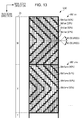
- Figs. 13 and 14 are explanatory diagrams illustrating a mask for forming a dot recording pattern in each pass according to a fourth embodiment.
- N which is the number of passes of the multi-pass recording is 4.
- the mask areas in which dot rates different from each other are assigned are divided by boundaries in parallel with each other in the sub-scan direction.
- the mask areas in which dot rates different from each other are assigned are formed so as to have zigzag shapes, similarly to the second embodiment.
- the mask MSE is configured by a first mask MS1ae and a second mask MS1a*e ( Fig. 13 ) for dot recording in the pixel position of the even number row, and a third mask MS1ao and a fourth mask MS1a*o ( Fig. 14 ) for dot recording in the pixel position of the odd number row.
- the first mask MS1ae and the second mask MS1a*e relate to the even-numbered pixels in the main scan direction, and the pixel positions of the dot recording have a complementary relationship with each other.
- the third mask MS1ao and the fourth mask MS1a*o relate to the odd-numbered pixels in the main scan direction, and the pixel positions of the dot recording have a complementary relationship with each other.
- the first mask MS1ae is sequentially divided into four mask areas Mulae (dot rate of even number row is 67%), Mmlae (dot rate of even number row is 50%), Mdlae (dot rate of even number row is 33%), and Mmlae (dot rate of even number row is 50%).
- a left and right boundary of each mask area has a non-linear shape with a tilt of 45 degrees with respect to the main scan direction and the sub-scan direction, and has a shape of mirror symmetry with respect to a center in the sub-scan direction.
- the second mask MS1a*e has four mask areas Mu1a*e, Mm1a*e, Md1a*e, and Mm1a*e which have a complementary relationship with the four mask areas Mulae, Mmlae, Mdlae, and Mmlae of the first mask MS1ae, and a left and right boundary of each mask area has a linear shape with a tilt of 45 degrees with respect to the main scan direction and the sub-scan direction, and has a shape of mirror symmetry with respect to a center in the sub-scan direction.
- the third mask MS1ao of Fig. 14 is sequentially divided into four sections of the four mask areas Mulao (dot rate of even number row is 67%), Mmlao (dot rate of even number row is 50%), Mdlao (dot rate of even number row is 33%), and Mmlao (dot rate of even number row is 50%).
- a left and right boundary of each of the four mask areas Mulao, Mmlao, Mdlao, and Mmlao has a linear shape with a tilt of 45 degrees with respect to the main scan direction and the sub-scan direction, and has a shape of mirror symmetry with respect to the center in the sub-scan direction.
- the fourth mask MS1a*o also has the four mask areas Mu1a*o, Mm1a*o, Md1a*o, and Mm1a*o which have complementary relationships with the third mask MS1ao.
- a left and right boundary of each mask area has a linear shape with a tilt of 45 degrees with respect to the main scan direction and the sub-scan direction, and has a shape of mirror symmetry with respect to the center in the sub-scan direction.
- the dot recording of each area is completed by the dot recording of the odd number rows in the main scan direction in the first and second passes, and by the dot recording of the even number rows in the main scan direction in the third and fourth passes, among the four passes.
- the mask MSE which is used in the dot recording of each pass in the same manner as the mask MSD ( Fig. 11 ) according to the third embodiment, is set in such a manner that the dot rate is changed repeatedly, gradually and periodically for each section of a constant length of a plurality of pixels lined up in the main scan direction. Thus, it is possible to suppress the banding along the main scan direction from occurring.
- the dot recording of the odd number rows and the dot recording of the even number rows are divided, and thereby, further, an effect that the main scan direction is gradually and periodically divided for a constant section is increased, and it is possible to further suppress the banding along the main scan direction from occurring.
- a left and right boundary of each mask area is a linear shape with a tilt of 45 degrees so as not to be a linear shape in parallel with the main scan direction and the sub-scan direction, it is possible to suppress the banding along the sub-scan direction from occurring.
- the mask is set in such a manner that all the nozzles do not eject the inks simultaneously, it is possible to suppress a concern that a landing position of the ink ejected by an airflow occurring according to the ink ejected from the nozzle is different from the assumed position, compared to a case where the inks are simultaneously ejected from all the nozzles.
- the number of passes of the multi-pass recording is 2 or 4, but as the number of N, an arbitrary integer equal to or greater than 2 can be used.
- the dot rate formed in each main scan pass can be set to an arbitrary value.
- an amount of transmission of the sub-scan performed after one time of main scan pass is ended be set to a predetermined value corresponding to 1/N of the head height.
- the left and right boundary (boundary extending in the sub-scan direction) of the mask area has a zigzag shape which is configured by a linear line, but instead of that, a non-linear shape (including a curve or a polygonal line) of other type may be employed.
- the dot rate is changed in each section of a predetermined length along the main scan direction, but the length of each section may be changed in each section.
- the length of each section along the main scan direction have a range of four pixels to 10 pixels.
- the responsible pixels on which the dot recording is performed be not four or more continuous pixels in the main scan direction (the number of consecutive responsible pixels is equal to or less than three).
- the non-responsible pixels on which the dot recording is not performed be not four or more continuous pixels in the main scan direction (the number of consecutive non-responsible pixels is equal to or less than three). In this way, the responsible pixel and the non-responsible pixel are dispersed, and thereby it is possible more than usual for it to be difficult for the banding to stand out.
- the dot rate of a plurality of sections three values of 33%, 50%, and 67% are used, but any values other than these can be used.
- the number of types of section with a different dot rate may be equal to or greater than two, but it is preferable that the number be equal to or greater than three. In this way, dot forming states are respectively changed in three or more sections which have different dot rates and thereby there is an advantage that it is difficult for the banding to stand out.
- an average value of the dot rate in each of the plurality of sections be (1/N ⁇ 100)% (N is the number of passes of multi-pass recording).
- N is the number of passes of multi-pass recording.
- the average value of the dot rate in each of the plurality of sections lined up in the main scan direction is 50% ( Figs. 4 and 9 ).
- the average value of the dot rate in the plurality of sections lined up in the main scan direction is 25% ( Fig. 11 , Fig. 13 , and Fig. 14 ).
- the values (67%, 50%, 33%, and 50%) of the dot rate which are described in Fig. 11 , Fig. 13 , and Fig. 14 are values with regard to the pixel positions of the odd number row or the pixel position of the even number row, the values are two times the value of the dot rate with regard to all pixel positions.
- the average value of the dot rate in the plurality of sections lined up in the main scan direction may be 25%.
- the dot rate it is preferable that a plurality of pairs in which two values which are complementary with respect to (1/N ⁇ 100)% are set as one pair be used.
- a plurality of pairs in which two values which are complementary with respect to (1/N ⁇ 100)% are set as one pair be used.
- the first embodiment Fig. 4
- 67% and 33% are used as first pair
- 50% and 50% are used as a second pair. If the values of such dot rates are used, there is an advantage that it is easy to set the average value of the dot rate in each of the plurality of sections lined up in the main scan direction to (1/N ⁇ 100)%.
- the recording head moves in the main scan direction, but if the ink is ejected by relatively moving the recording medium and the recording head in the main scan direction, the invention is not limited to the above-described configuration.
- the recording medium may be moved in the main scan direction in a state where the recording head is stopped, and in addition, both the recording medium and the recording head may be moved in the main scan direction.
- the recording medium and the recording head may be moved relatively.
- the recording may be performed by moving a head portion in XY directions with regard to the recording medium mounted (fixed) on a table. That is, the recording medium and the recording head may be configured so as to be able to relatively move in at least one of the main scan direction and the sub-scan direction.
- the printing apparatus which ejects the ink on the printing paper is described, but the invention can also be applied to various dot recording apparatuses in addition to the printing apparatus, and can also be applied to an apparatus which forms dots by ejecting droplets on a substrate, for example.
- the invention may employ a liquid ejection apparatus which ejects or discharges liquids other than the ink, and can be used for various liquid ejecting apparatuses which include liquid ejecting heads or the like which eject droplets of a small amount.
- droplets means a state of liquid which is ejected from the above-described liquid ejecting apparatus, and includes drawing a trail in a grain shape, a tear shape, and a thread shape.
- the liquids described above may be materials which can be ejected by the liquid ejecting apparatus.
- the liquid may be a state where a material is in a liquid phase, and includes a liquid state with high or low viscosity, a sol, gel, water, another inorganic solvent, an organic solvent, a solution, a liquid resin, a flow state such as a liquid state metal (molten metal liquid), not only a liquid with material in one state but also that in which particles of functional materials consisting of solid materials such as pigments or metal particles are dissolved, dispersed or mixed in a solvent, or the like.
- a liquid state metal molten metal liquid
- ink or liquid crystal as described in the above-described embodiments are included.
- the ink includes various liquid compositions such as a general water-based ink, oil-based ink and gel ink, and hot-melt ink.
- a liquid ejecting apparatus that ejects liquid which contains materials such as electrode materials or color materials used in manufacturing a liquid crystal display, an EL (Electroluminescence) display, a surface light emitting display, or a color filter or the like in a dispersed or melted form, may be used.
- the liquid ejecting apparatus may be a liquid ejecting apparatus which ejects living organic material used in manufacturing a bio chip, a liquid ejecting apparatus used as a precision pipette which ejects liquid consisting of a sample, a textile printing apparatus, a micro-dispenser, or the like.
- a liquid ejecting apparatus which ejects lubricating oil into a precision machine such as a watch or a camera using a pinpoint, a liquid ejecting apparatus which ejects transparent resin liquid such as ultraviolet curable resin onto a substrate in order to form a minute hemispherical lens (optical lens) or the like used in an optical communication element, or a liquid ejecting apparatus which ejects etching liquid such as an acid or an alkali in order to etch a substrate or the like, may be employed.
Abstract
Description
- The present invention relates to a dot recording apparatus, a dot recording method, and a computer program therefor.
- It is known that a printing apparatus which functions as a dot recording apparatus and which forwardly and backwardly moves a plurality of recording heads which eject inks of different colors with respect to recording materials, performs a main scan at the time of a forward movement and a backward movement, and thereby performs printing (for example,
JP-A-6-22106 - However, in the above-described printing apparatus of the related art, each pixel group has a rectangular shape. Since a boundary between the pixel groups is configured with a side in parallel with a main scan direction and a side in parallel with a sub-scan direction, a long boundary extending in the main scan direction and a long boundary extending in the sub-scan direction are formed by a set of the boundaries of the pixel groups adjacent to each other. For this reason, there is a problem that banding (image quality deterioration area) along such long boundaries easily occurs and stands out. In addition, in the printing apparatus which performs the main scan and forms dots, there is a problem that the banding of the main scan direction easily stands out. In particular, in the above-described printing apparatus of the related art, since a pixel group which is a target of ink ejection and a pixel group which is not the target of ink ejection are arranged in a form of being tiled with each other, there is a problem that the banding of the main scan direction occurring at such a boundary easily stands out. These problems are not limited to the printing apparatus, and commonly occur in a dot recording apparatus which records dots on a recording medium (dot recording medium).
- The invention can be realized in the following forms or application examples.
- (1) According to an aspect of the invention, there is provided a dot recording apparatus including, a recording head which has a plurality of nozzles, a main scan driving mechanism which relatively moves the recording head and a recording medium in a main scan direction and performs a main scan pass that forms dots on the recording medium, a sub-scan driving mechanism which performs a sub-scan which relatively moves the recording medium and the recording head in a sub-scan direction that intersects with the main scan direction, and a control unit, in which the control unit performs multi-pass recording which completes forming of the dots on a main scan line by N (N is an integer equal to or greater than 2) times of the main scan passes, in which a dot rate which represents a rate of pixels in which dot recording is performed in each main scan pass of the multi-pass recording is set so as to be changed gradually and periodically over a plurality of sections in the main scan direction, and in which the number of values of the dot rates different from each other in the plurality of sections lined up in the main scan direction is set so as to be equal to or greater than 3. According to the aspect of the dot recording apparatus, since a dot rate of each section in the main scan direction of each main scan pass is set so as to be changed gradually and periodically, dot recording in the main scan direction can be divided for each section, and thereby banding along the main scan direction can be suppressed from occurring. In addition, by changing gradually and periodically the dot rate for each section, a rapid change of the dot rate for each section along the main scan direction can be suppressed, and thus it is possible to configure the banding along the main scan direction so as not to stand out.
- (2) In the dot recording apparatus, each section may be separated by a boundary with a non-linear shape repeated in a predetermined period along the sub-scan direction. In the dot recording apparatus, since the dot rate of not only the main scan direction but also the sub-scan direction can be changed gradually and periodically, the banding along the sub-scan direction can be suppressed from occurring. In addition, since a rapid change of the dot rate for each section along the sub-scan direction can be suppressed, it is possible to configure the banding occurring along the sub-scan direction so as not to stand out.
- (3) In the dot recording apparatus, the non-linear shape is set in such a manner that a shape of a first half period and a shape of a second half period of the period have mirror symmetry. In this case, it is easy to set a complementary relationship between a first pass and a second pass.
- (4) In the dot recording apparatus, the non-linear shape may be a zigzag shape with a tilt of 45 degrees with respect to the main scan direction and the sub-scan direction. In this case, it is easy to set the complementary relationship between the first pass and the second pass, and it is possible to realize the most efficient suppression of the banding in the main scan direction and suppression of the banding in the sub-scan direction.
- In addition, the invention can be realized by various forms such as a recording method, a computer program, and a recording medium in which the computer program is stored, in addition to the dot recording apparatus.
- Embodiments of the invention will now be described by way of example only with reference to the accompanying drawings, wherein like numbers reference like elements.
-
Fig. 1 is an explanatory diagram illustrating a configuration of a dot recording system. -
Fig. 2 is an explanatory diagram illustrating an example of a configuration of a nozzle row of a recording head. -
Fig. 3 is an explanatory diagram illustrating both a position of a nozzle row of two main scan passes of dot recording and a recording area at the position, according to a first embodiment. -
Fig. 4 is an explanatory diagram illustrating a mask for forming a dot recording pattern in each pass. -
Fig. 5 is an explanatory diagram illustrating a specified example of the mask inFig. 4 . -
Fig. 6 is an explanatory diagram illustrating a state where dot recording is performed by a first pass and a second pass. -
Fig. 7 is an explanatory diagram illustrating a first modification example of a mask for forming a dot recording pattern in each pass. -
Fig. 8 is an explanatory diagram illustrating a second modification example of the mask for forming the dot recording pattern in each pass. -
Fig. 9 is an explanatory diagram illustrating a mask for forming a dot recording pattern in each pass, according to a second embodiment. -
Fig. 10 is an explanatory diagram illustrating both a position of a nozzle row of four main scan passes and a recording area at the position, according to a third embodiment. -
Fig. 11 is an explanatory diagram illustrating a mask for forming a dot recording pattern in each pass. -
Figs. 12A to 12E are explanatory diagrams illustrating a state where dot recording is performed within one area in the first to fourth passes. -
Fig. 13 is an explanatory diagram illustrating a mask for forming a dot recording pattern in each pass according to a fourth embodiment. -
Fig. 14 is another explanatory diagram illustrating a mask for forming a dot recording pattern in each pass according to the fourth embodiment. -
Fig. 1 is an explanatory diagram illustrating a configuration of a dot recording system. Thedot recording system 10 includes animage processing unit 20 and adot recording unit 60. Theimage processing unit 20 generates print data for thedot recording unit 60 from image data (for example, image RGB data). - The image processing unit includes a CPU 40 (referred to as "
control unit 40"), aROM 51, aRAM 52, an EEPROM 53, and anoutput interface 45. TheCPU 40 has functions of a colorconversion processing portion 42, ahalftone processing portion 43, and arasterizer 44. Such functions are realized by a computer program. The colorconversion processing portion 42 converts multiple gradation RGB data of an image into ink amount data which represents an amount of ink of a plurality of colors. Thehalftone processing portion 43 generates dot data illustrating a dot forming state for each pixel, by performing halftone processing with respect to the ink amount data. Therasterizer 44 rearranges the dot data generated by the halftone processing into the dot data which is used in each main scan performed by thedot recording unit 60. An operation of dot recording which is explained in the following various embodiments is a rasterizing operation (that is, an operation which is represented by raster data) which is realized by therasterizer 44. - The
dot recording unit 60 is, for example, a serial type ink jet recording apparatus, and includes acontrol unit 61, acarriage motor 70, adriving belt 71, apulley 72, asliding shaft 73, apaper feeding motor 74, apaper feeding roller 75, acarriage 80,ink cartridges 82 to 87, and arecording head 90. - The
driving belt 71 is stretched between thecarriage motor 70 and thepulley 72. Thedriving belt 71 is attached to thecarriage 80. In thecarriage 80, theink cartridges 82 to 87 which respectively contain, for example, cyan ink (C), magenta ink (M), yellow ink (Y), black ink (K), light cyan ink (Lc), and light magenta ink (Lm) are provided. In addition, various inks other than these inks can be used as the ink. In therecording head 90 in the lower portion of thecarriage 80, nozzle rows corresponding to the above-described various color inks are formed. Ifsuch ink cartridges 82 to 87 are mounted on thecarriage 80 from above, the ink can be supplied from each cartridge to therecording head 90. Thesliding shaft 73 is arranged in parallel with the driving belt, and penetrates thecarriage 80. - If the
carriage motor 70 drives thedriving belt 71, thecarriage 80 moves along thesliding shaft 73. This direction is referred to as a "main scan direction". Thecarriage motor 70, the drivingbelt 71, and the slidingshaft 73 configure a main scan driving mechanism. According to the movement of thecarriage 80 in the main scan direction, theink cartridges 82 to 87 and therecording head 90 also move in the main scan direction. During the movement in the main scan direction, the ink is ejected from the nozzles (described later) arranged in therecording head 90 to the recording medium P (typically, printing paper), and thereby dot recording is performed on the recording medium P. In this way, the movement in the main scan direction of therecording head 90 and ejecting of the ink are referred to as a main scan, and one time of main scan is referred to as a "main scan pass" or merely as a "pass". - The
paper feeding roller 75 is connected to thepaper feeding motor 74. During recording, the recording medium P is inserted onto thepaper feeding roller 75. If thecarriage 80 moves to an end portion in the main scan direction, thecontrol unit 61 rotates thepaper feeding motor 74. As a result, thepaper feeding roller 75 also rotates, and moves the recording medium P. A relative movement between the recording medium P and therecording head 90 is referred to as a sub-scan, and a relative movement direction is referred to as a "sub-scan direction". Thepaper feeding motor 74 and thepaper feeding roller 75 configure a sub-scan driving mechanism. The sub-scan direction is a direction (orthogonal direction) which is perpendicular to the main scan direction. However, the sub-scan direction is not required to be always orthogonal to the main scan direction, and may intersect. In addition, in general, a main scan operation and a sub-scan operation are alternately performed. In addition, as a dot recording operation, it is possible to perform at least one of a unidirectional recording operation which performs the dot recording by only the main scan of a forward path, and a bidirectional recording operation which performs the dot recording by the main scans of both directions of the forward path and a backward path. In the main scan of the forward path and the main scan of the backward path, the direction of the main scan is merely reversed, and thus, hereinafter, the forward path and the backward path will be described without being distinguished as long as there is no particular necessity. - The
image processing unit 20 may be configured integrally with thedot recording unit 60. In addition, theimage processing unit 20 may be configured separately from thedot recording unit 60 by being built in a computer (not illustrated). In this case, theimage processing unit 20 may be implemented by the CPU as printer driver software (computer program) stored in the computer. -
Fig. 2 is an explanatory diagram illustrating an example of a configuration of a nozzle row of therecording head 90. In addition, inFig. 2 , two recording heads 90 are illustrated. However, therecording head 90 may be one piece and may be two or more. The tworecording heads nozzles 92 which are lined up in the sub-scan direction at a constant nozzle pitch dp. Anozzle 92x of an end portion of the nozzle row 91 of thefirst recording head 90a is shifted in the sub-scan direction by the same distance as the nozzle pitch dp of the nozzle row 91, from anozzle 92y of an end portion of the nozzle row 91 of thesecond recording head 90b. In this case, the (combined) nozzle row for one color, of the tworecording heads Fig. 2 ) which has two times the number of nozzles for one color of onerecording head 90. In the following description, a method of performing the dot recording of one color by using thesame nozzle row 95 will be described but it should be understood that the nozzle row may also be a combined nozzle row for example formed by two or more recording heads. In addition, in the first embodiment, the nozzle pitch dp and a pixel pitch on the recording medium P are the same as each other. However, the nozzle pitch dp can also be a multiple of the pixel pitch on the recording medium P. In the case of the latter, so-called interlacing recording (an operation of performing an operation of recording the dots by a pass after the second pass, in such a manner that a dot gap between the main scan lines recorded in the first pass is filled) is performed. The nozzle pitch dp is a value (0.035 mm) corresponding to, for example, 720 dpi. -
Fig. 3 is an explanatory diagram illustrating both a position of anozzle row 95 of two main scan passes of dot recording and a recording area at the positions, according to a first embodiment. In the following description, a case where dots are formed on all the pixels of the recording medium P by using ink (for example, cyan ink) of one color will be described as an example. In the present specification, a dot recording operation which completes forming of the dots on each main scan line by N (N is an integer equal to or greater than two) main scan passes is referred to as "multi-pass recording". In the present embodiment, N which is the number of passes of multi-pass recording is 2. In the first pass (1P) and the second pass (2P), the position of thenozzle row 95 is shifted in the sub-scan direction by a distance corresponding to half of a head height Hh. Here, "the head height Hh" means a distance which is represented by Mxdp (M is the number of nozzles of thenozzle row 95 and dp is the nozzle pitch). - In the first pass, the dot recording is performed in 50% of all pixels in an area Q1 which is configured with the main scan lines through which the nozzles of an upper half of the
nozzle row 95 penetrate, and in 50% of all pixels in an area Q2 which is configured with main scan lines through which the nozzles of a lower half of thenozzle row 95 penetrate, in the recording medium P. In the second pass, the dot recording is performed in the remaining 50% of the pixels where the dots are not formed in the first pass of all the pixels of the area Q2 which is configured with the main scan lines through which the nozzles of the upper half of thenozzle row 95 penetrate, and in 50% of all pixels in an area Q3 which is configured with main scan lines through which the nozzles of the lower half of thenozzle row 95 penetrate, in the recording medium P. Thus, 50% of the area Q2 is recorded, respectively, by each of the first and second passes, and the recording of a total of 100% of the pixels is performed. In addition, in the third pass, the dot recording is performed in the remaining 50% of the pixels of the area Q3, and in the pixels of 50% of the area Q4 (not illustrated) next thereto. In addition, here, it is assumed that the image (beta image) in which dots are formed on all the pixels of the recording medium P is formed on the recording medium P, but the recorded image (printed image) which is represented by actual dot data includes the pixels which actually form dots in the recording medium P and the dots which are not actually formed in the recording medium P. That is, whether or not the dots on each pixel of the recording medium P are actually formed is determined by the dot data which is generated by the halftone processing. In the present specification, the term "dot recording" means "dot is formed or not formed". In addition, the term "dot recording is performed" is used as a term which means "it is responsible for dot recording", regardless of whether or not the dots on the recording medium P are actually formed. -
Fig. 4 is an explanatory diagram illustrating a mask for forming a dot recording pattern in each pass, andFig. 5 is an explanatory diagram illustrating a specified example of the mask inFig. 4 . The mask MS is configured with a first mask MS1 which is assigned with respect to the nozzle group X of the upper half of thenozzle row 95, and a second mask MS1* which is assigned with respect to the nozzle group Y of the lower half of thenozzle row 95. The mask MS is repeatedly arranged along the main scan direction on the recording medium P. - The first mask MS1 is configured by four mask areas Mu, Mm, Md and Mm of rectangular shape which are sequentially separated in each section with a constant length of an amount of a plurality of dots lined up in the main scan direction. The first mask area Mu is an area in which the nozzle group X of the upper half has a dot rate (67% in the present example), which represents a rate responsible for the dot recording, more than 50%, within the area. The third mask area Md is an area in which the dot rate (33% in the present example) of the nozzle group X of the upper half is less than 50%, within the area. The dot rate of the first mask area Mu and the dot rate of the third mask area Md are set in such a manner that the average of the dot rates is 50%. The second and fourth mask areas Mm are areas in which the dot rate of each nozzle of the upper head X in the area is 50%. Thus, the dot rate in the area of the first mask MS1 becomes an average of 50%. In addition, the first mask MS1 is repeatedly arranged in the main scan direction, and thereby the dot rate of each area lined up in the main scan direction is changed gradually and periodically. In addition, the dot rate of each of the four areas is not limited thereto, and the dot rate of each area is changed gradually and periodically, and an average of the dot rate may be set so as to be 50%.
- The first mask area Mu, for example, as illustrated in
Fig. 5 , is set as one area which is divided into 4x12 pixels, and is configured by setting two thirds of all the pixels in the area as the pixels (hereinafter, referred to as "responsible pixel") responsible for the dot recording, and by setting the remaining third (the rest of) the pixels as the pixels (hereinafter, referred to as "non-responsible pixel") not responsible for the dot recording. In addition, the third mask area Md, for example, as illustrated inFig. 5 , is also configured by setting a third of all the pixels in the area as responsible pixels, and by setting the other two thirds (the rest of) the pixels as non-responsible pixels. Furthermore, also, the second and fourth mask areas Mm, for example, as illustrated inFig. 5 , are configured by setting a half of all the pixels in the area as responsible pixels, and by setting the other half of (the rest of) the pixels as non-responsible pixels. In addition, it is preferable that the responsible pixels and the non-responsible pixels be set so as to be respectively distributed without deviation, in the area. In addition, also in an area with the same dot rate, the arrangement position of the responsible pixels and the non-responsible pixels is not necessarily the same and can be set at random. - The second mask MS1*, as illustrated in
Fig. 4 , is configured by four mask areas Mu*, Mm*, Md* and Mm* which are sequentially separated along the main scan direction so as to coincide with a boundary along the sub-scan direction of each mask area of the first mask MS1. A fifth mask area Mu*, as illustrated inFig. 4 , is an area with a rate (33% in the present example) which is set in such a manner that the dot rate of the nozzle group Y of the lower half in the area is brought into a complementary relationship with the first mask area Mu. Specifically, the fifth mask area Mu*, as illustrated inFig. 5 , is set in such a manner that the non-responsible pixels in the first mask area Mu become the responsible pixels and the responsible pixels become the non-responsible pixels. In addition, a seventh mask area Md*, as illustrated inFig. 4 , is an area with a rate (67% in the present example) which is set in such a manner that the dot rate of the nozzle group Y of the lower half in the area is brought into a complementary relationship with the third mask area Md. Specifically, the seventh mask area Md*, as illustrated inFig. 5 , is set in such a manner that the non-responsible pixels in the third mask area Md become the responsible pixels and the responsible pixels become the non-responsible pixels. In the same manner, sixth and eighth mask areas Mm*, as illustrated inFig. 4 , are also areas with a rate (50% in the present example) which is set in such a manner that the dot rate of the nozzle group Y of the lower half in the area is brought into the complementary relationship with the second and fourth mask areas Mm. Specifically, the sixth and eighth mask areas Mm*, as illustrated inFig. 5 , are set in such a manner that the non-responsible pixels in the second and fourth mask areas Mm become the responsible pixels and the responsible pixels become the non-responsible pixels. -
Fig. 6 is an explanatory diagram illustrating a state where dot recording is performed by afirst pass 1P and asecond pass 2P. In the first pass, thenozzle row 95 of the first pass illustrated in the left-hand side ofFig. 6 moves in the main scan direction, and thereby, in an area Q1 illustrated in the right-hand side ofFig. 6 , dot recording responding (corresponding) to the first mask MS1 (Fig. 5 ) assigned in the nozzle group X1 of the upper half of the mask MS illustrated inFig. 4 is performed. In addition, in an area Q2, dot recording responding to the second mask MS1* (Fig. 6 ) assigned in the nozzle group Y1 of a lower half of the mask MS is performed. In addition, the responsible pixels of thefirst pass 1P are illustrated by a circle with right diagonal upward hatched lines. - In the second pass, the
nozzle row 95 is shifted by an amount of half (12 pixels in the present example) of the head height Hh (24 pixels in the present example) in the sub-scan direction from the position of thefirst pass 1P, and then moves in the main scan direction. As a result, in the area Q2, dot recording responding to the first mask MS1* assigned in the nozzle group X2 of the upper half of the mask MS is performed. In addition, in area Q3, dot recording responding to the second mask MS1* assigned in the nozzle group Y2 of the lower half of the mask MS is performed. In addition, the responsible pixels of the second pass are illustrated by a circle with left diagonal upward hatched lines. As a result, the dot recording of all the pixels in the area Q2 is completed. - In the same manner, also in the third or subsequent passes, the dot recording according to the mask MS is performed. In this way, moving the
nozzle row 95 in the main scan direction and ejecting the ink, and relatively moving the recording medium P in the sub-scan direction are alternately repeated several times, and thereby the dot recording on the recording medium P is completed. In addition, since the dot recording is not performed at some positions of the pixels in the area Q1 in the upper portion, a printing target area (recording target area) in which the image is actually printed (recorded) is at or lower than the area Q2. This is similarly applied to the other embodiments described later. - In addition, in the description for
Fig. 6 , the mask MS also moves as thenozzle row 95 moves in the sub-scan direction, but instead of this, the mask MS may be arranged repeatedly in a tiled form in the main scan direction and the sub-scan direction on the recording medium P, and thereby the responsible pixels may be determined. In a case of the latter, the pixel with the hatched lines inFig. 5 is treated as indicating a pixel which performs the dot recording in the odd-numbered main scan passes, and the pixel without the hatched lines is treated as indicating a pixel which performs the dot recording in the even-numbered main scan passes. - The dot recording operation described using
Figs. 3 to 6 is realized by a rasterizing operation performed by therasterizer 44. That is, the dot recording operation is independent of the actual printing target image, and is an operation of determining in which pass and by which nozzle the dot recording of each pixel on each main scan lines is performed. Whether or not the dot is actually formed at each pixel is determined according to the printing target image. In addition, the mask MS (Figs. 3 and4 ) used by the rasterizing operation is stored in a non-volatile memory device such as theROM 51 or theEEPROM 53. In addition, the first mask MS1 and the second mask MS1* which configure the mask MS may be configured so as to be separately stored. - In the present embodiments, the dot recording of each area is completed by the dot recording performed by the two passes. At this time, the mask MS which is used by the dot recording in each pass is set in such a manner that such a dot rate is changed repeatedly, gradually and periodically in an arrangement sequence of a plurality of sections separated by a section of a constant length of a plurality of pixels lined up in the main scan direction. In a case where the dot recording is performed using the mask, the main scan line is divided for each constant section, the dot rate is changed gradually and periodically over the plurality of sections, and thus it is possible to suppress the banding along the main scan direction from occurring. In addition, the dot rate is changed gradually and periodically for each section, and thereby it is possible to suppress a rapid change of the dot rate for each section along the main scan direction, and thus it is possible to prevent the banding from easily standing out due to rapid change of dot rate occurring at the sections adjacent to each other. In addition, since the mask is set in such a manner that all the nozzles do not eject the inks simultaneously, it is possible to suppress a concern that a landing position of the ink ejected by an airflow occurring according to the ink ejected from the nozzle is different from the assumed position, compared to a case where the inks are simultaneously ejected from all the nozzles.
-
Fig. 7 is an explanatory diagram illustrating a first modification example of a mask for forming a dot recording pattern in each pass. The mask MS ofFig. 4 illustrates a configuration in which one piece of the first mask MS1 is arranged with respect to the nozzle group X of the upper half of thenozzle row 95, and one piece of the second mask MS1* is arranged with respect to the nozzle group Y of the lower half of thenozzle row 95. In contrast, a mask MSA ofFig. 7 has a configuration in which a plurality of the first masks MS1 is arranged along a nozzle height direction (sub-scan direction) with respect to the nozzle group X of the upper half, and in the same manner, has a configuration in which a plurality of the second masks MS1* is arranged along the nozzle height direction, also with respect to the nozzle group Y of the lower half. In this case, the first mask MS1 and the second mask MS1* are separately stored one by one in the non-volatile memory device, and they are repeatedly used, and thereby the mask MSA illustrated inFig. 7 may be configured so as to be realized. In this way, there is an advantage that an amount of mask data is reduced. -
Fig. 8 is an explanatory diagram illustrating a second modification example of the mask for forming the dot recording pattern in each pass. A mask MSB ofFig. 8 has a configuration in which the first mask MS1 and the second mask MS1*, as one pair, are arranged alternately and plurally in the sub-scan direction with respect to the nozzle group X of the upper half, and the second mask MS1* and the first mask MS1, as one pair, are arranged alternately and plurally in the sub-scan direction with respect to the nozzle group Y of the lower half. In the mask MSB, in the same manner as the mask MSA ofFig. 7 , there is an advantage that an amount of the mask data which is stored in the non-volatile memory device is reduced. In addition, because the same masks are not arranged along the sub-scan direction like the mask MSA ofFig. 7 and different masks are alternately arranged along the sub-scan direction, there is an effect that there is division into sections each having a constant length along the sub-scan direction, and compared to the mask MSA of a first modification example, it is possible to suppress the banding along the sub-scan direction from occurring. -
Fig. 9 is an explanatory diagram illustrating a mask for forming a dot recording pattern in each pass, according to a second embodiment. Also in the second embodiment, N which is the number of passes of the multi-pass recording is 2. In the mask MS of the first embodiment illustrated inFig. 4 described above, the mask areas in which dot rates different from each other are assigned are divided by boundaries in parallel with each other in the sub-scan direction. In contrast, in a mask MSC according to the second embodiment, the mask areas in which dot rates different from each other are assigned are formed so as to have zigzag shapes. In other words, the boundaries of the mask areas of the mask MSC according to the second embodiment have zigzag shapes, or the mask MSC according to the second embodiment has areas formed in the zigzag shapes in such a manner that the rate at which the nozzle group that is responsible for the dot recording is changed in each predetermined range along a direction which intersects with the main scan direction and the sub-scan direction. - The mask MSC is configured with a first mask MS1a corresponding to the nozzle group X of the upper half, and a second mask MS1a* corresponding to the nozzle group Y of the lower half. The second mask MS1a* has a complementary relationship with the first mask MS1a. The first mask MS1a, in the same manner as the first mask MS1 (
Fig. 4 ) according to the first embodiment, is divided into four types of mask areas Mula, (dot rate is 67%), Mmla (dot rate is 50%), Mdla (dot rate is 33%), and Mmla (dot rate is 50%). However, in such four mask areas Mula, Mmla, Mdla, and Mmla, a left and right boundary (that is, a boundary along the sub-scan direction) of each mask area has a linear shape with a tilt of 45 degrees with respect to the main scan direction and the sub-scan direction, and has a shape of mirror symmetry with respect to a center in the sub-scan direction. The second MS1a* has four mask areas Mu1a*, Mm1a*, Md1a*, and Mm1a* which have a complementary relationship with the four mask areas Mula, Mmla, Mdla, and Mmla of the first mask MS1a, and a left and right boundary of each mask area has a linear shape with a tilt of 45 degrees with respect to the main scan direction and the sub-scan direction, and has a shape of mirror symmetry with respect to the center in the sub-scan direction. - In the same manner as the mask MS1 (
Fig. 4 ) according to the first embodiment, the mask MSC according to the second embodiment is also set in such a manner that the dot rate for each section of a constant length of an amount of a plurality of pixels lined up in the main scan direction is changed repeatedly, gradually and periodically. In the same manner as the mask according to the first embodiment, in a case where the dot recording is performed using the mask MSC, the main scan line is divided for each constant section, the dot rate is changed gradually and periodically over the plurality of sections, and thereby it is possible to suppress the banding along the main scan direction from occurring. In addition, the dot rate for each section is changed gradually and periodically, and thereby it is possible to suppress a rapid change of the dot rate for each section along the main scan direction, and thus it is possible to suppress the banding from easily standing out due to the rapid change of the dot rate at the sections adjacent to each other. - In addition, in the mask MSC according to the second embodiment, the boundary of the mask area with the dot rates different from each other has a linear shape with a tilt of 45 degrees so as not to be a linear shape along the main scan direction and the sub-scan direction. Thus, division into a plurality of sections for each constant length can be done gradually and periodically, along not only the main scan direction but also the sub-scan direction. In this way, it is also possible to suppress the banding along the sub-scan direction from occurring. In addition, since the mask is set in such a manner that all the nozzles do not perform the dot recording simultaneously, it is possible to suppress a concern that a landing position of the ink ejected by an airflow occurring according to the ink ejected from the nozzle is different from the assumed position, compared to a case where the inks are simultaneously ejected from all the nozzles.
- In addition, in the above description, a case where the boundary of each section is a linear shape with a tilt of 45 degrees is described as an example, but the boundary is not limited thereto, and can be a linear shape with an arbitrary angle with respect to the main scan direction and the sub-scan direction. In addition, also in the second embodiment, it is possible to make modifications in the same manner as the mask of the modification examples described in
Figs. 7 and8 . Such modifications can also be applied to the other embodiments described in the following description. -
Fig. 10 is an explanatory diagram illustrating both a position of thenozzle row 95 of four main scan passes and a recording area at the position, according to a third embodiment. In the first and second embodiments, the dot recording at the position of all the pixels on each main scan line is completed by two passes, but in the third embodiment, the dot recording at the position of all the pixels on each main scan line is completed by four passes. That is, in the third embodiment, N which is the number of passes of multi-pass recording is 4. At this time, in the first and second passes, the dot recording at the odd-numbered pixel positions in the main scan direction is performed, and in the third and fourth passes, the dot recording at the even-numbered pixel positions is performed. In addition, in the moving of the recording medium P toward the sub-scan direction which is performed after each pass, the recording medium P moves to a lower side in the sub-scan direction by a distance of a quarter of the head height Hh. - For example, in the area Q4, the dot recording is performed in the pixels of 50% of the odd-numbered pixels in the first pass, and the dot recording is performed in the other 50% of the odd-numbered pixels in the second pass. Then, the dot recording is performed in the pixels of 50% of the even-numbered pixels in the third pass, and the dot recording is performed in the remaining 50% of the even-numbered pixels in the fourth pass. Thus, in the area Q4, 50% (25% with respect to all pixels) of the odd-numbered pixels are recorded in the first and second passes, respectively, and the even-numbered pixels are recorded by 50% (by 25% with respect to all pixels) in the third and fourth passes, respectively, so that the recording in 100% of the pixels is performed.
-
Fig. 11 is an explanatory diagram illustrating a mask for forming a dot recording pattern in each pass. The mask MSD is configured with a first mask area MSle which is assigned with respect to a first nozzle group W from the top, a second mask area MS1*e which is assigned with respect to a second nozzle group X from the top, a third mask area MS1o which is assigned with respect to a third nozzle group Y from the top, and a fourth mask area MS1*o which is assigned with respect to a fourth nozzle group Z from the top, among the nozzles in which the nozzle height Hh of thenozzle row 95 is divided into four groups. The first mask area MSle and the second mask area MS1*e are masks which are in charge of the dot recording of the even-numbered pixels in the main scan direction, and positions of the dot recording in the even-numbered pixels have a complementary relationship with each other. In the same manner, the third mask area MS1o and the fourth mask area MS1*o are masks which are in charge of the dot recording of the odd-numbered pixels in the main scan direction, and positions of the dot recording in the odd-numbered pixels have a complementary relationship with each other. -
Figs. 12A to 12E are explanatory diagrams illustrating a state where dot recording is performed within area Q4 in the first to fourth passes. In thefirst pass 1P, as illustrated inFig. 12A , according to the fourth mask MS1*o which is assigned to the fourth nozzle group Z1 from the top of the mask MSD illustrated inFig. 11 , the dot recording of the odd-numbered pixels in the main scan direction is performed. In addition, in thesecond pass 2P, as illustrated inFig. 12B , according to the third mask MS1o which is assigned to the third nozzle group Y2 from the top of the mask MSD illustrated inFig. 11 , the dot recording of the odd-numbered pixels in the main scan direction is performed. As a result, the dot recording of the pixels of the odd number row in the main scan direction of the area Q4 is completed. In addition, the responsible pixels formed in the first and second passes are illustrated by a circle with left diagonal upward hatched lines. - In the
third pass 3P, as illustrated inFig. 12C , according to the second mask MS1*e which is assigned to the second nozzle group X3 from the top of the mask MSD illustrated inFig. 11 , the dot recording of the even-numbered pixels in the main scan direction is performed. In addition, in thefourth pass 4P, as illustrated inFig. 12D , according to the first mask MSle which is assigned to the first nozzle group W4 from the top of the mask MSD illustrated inFig. 11 , the dot recording of the even-numbered pixels in the main scan direction is performed. As a result, the dot recording of the pixels of the even number row in the main scan direction of the area Q4 is completed. In addition, the responsible pixels formed in the third and fourth passes are illustrated by a circle with right diagonal upward hatched lines. As a result of the above, as illustrated inFig. 12E , the dot recording of all the pixels of the area Q4 is completed by four times of passes. - In addition, in the same manner, also in the fifth or subsequent passes, in the (4q+1)th and (4q+2)th (q is an integer equal to or greater than 1) passes, the dot recording is performed by the third and fourth masks MS1o and MS1*o according to the odd number row in the main scan direction, and in the (4q+3)th and (4q+4)th passes, the dot recording is performed by the first and second masks MSle and MS1*e according to the even number row in the main scan direction. In this way, a main scan pass and a sub-scan pass are alternately and repeatedly performed several times, and thereby the dot recording on the recording medium P is completed.
- Also in the third embodiment, in the same manner as in the first embodiment, it is possible to suppress the banding along the main scan direction from occurring. Since the mask is set in such a manner that all the nozzles do not eject the inks simultaneously, it is possible to suppress a concern that a landing position of the ink ejected by an airflow occurring according to the ink ejected from the nozzle is different from the assumed position, compared to a case where the inks are simultaneously ejected from all the nozzles.
- In addition, in the third embodiment, in a case where the dot recording of each area is completed in four passes, a case where the dot recording at the pixel positions of the odd number rows is performed in the first and second passes, and the dot recording at the pixel positions of the even number rows is performed in the third and fourth passes is described as an example, but it may be set in such a manner that the dot recording of the even number rows is performed in the first and second passes, and the dot recording at the pixel positions of the odd number rows is performed in the third and fourth passes. In addition, it may be set in such a manner that the dot recording at the pixel position of one of the even number row or the odd number row is performed in the first and third passes, and the dot recording at the pixel position of the other row is performed in the second and fourth passes.
- In addition, the arrangement of the responsible pixels in the two masks MSle and Ms1*e in the upper portion of
Fig. 11 is the same as that in which the masks MS1 and MS1* illustrated inFig. 5 are applied to only the pixel position of the even number row (that is, in which each pixel row of the masks MS1 and MS1* ofFig. 5 is used as the even numbered pixel rows, and the odd-numbered pixel rows are inserted therebetween). In the same manner, the two masks MS1o and MS1*o in the lower portion ofFig. 11 are the same as those in which the masks MS1 and MS1* illustrated inFig. 5 are applied to only the pixel position of the odd number row. Thus, instead of the mask MSD ofFig. 11 , the mask MS ofFig. 5 is stored in the non-volatile memory device, and the applied pixel row of the mask MS is switched, and thereby it is possible to perform the rasterizing control according to the third embodiment. In this way, it is possible to reduce a memory capacity for the mask. Such a modification can also be applied to the other embodiments described in the following description. -
Figs. 13 and14 are explanatory diagrams illustrating a mask for forming a dot recording pattern in each pass according to a fourth embodiment. In the fourth embodiment, N which is the number of passes of the multi-pass recording is 4. In the mask MSD of the third embodiment illustrated inFig. 11 described above, the mask areas in which dot rates different from each other are assigned are divided by boundaries in parallel with each other in the sub-scan direction. In contrast, in the mask MSE according to the fourth embodiment, the mask areas in which dot rates different from each other are assigned are formed so as to have zigzag shapes, similarly to the second embodiment. - The mask MSE is configured by a first mask MS1ae and a second mask MS1a*e (
Fig. 13 ) for dot recording in the pixel position of the even number row, and a third mask MS1ao and a fourth mask MS1a*o (Fig. 14 ) for dot recording in the pixel position of the odd number row. The first mask MS1ae and the second mask MS1a*e relate to the even-numbered pixels in the main scan direction, and the pixel positions of the dot recording have a complementary relationship with each other. The third mask MS1ao and the fourth mask MS1a*o relate to the odd-numbered pixels in the main scan direction, and the pixel positions of the dot recording have a complementary relationship with each other. - In the same manner as the first mask MSle (
Fig. 11 ) according to the third embodiment, the first mask MS1ae is sequentially divided into four mask areas Mulae (dot rate of even number row is 67%), Mmlae (dot rate of even number row is 50%), Mdlae (dot rate of even number row is 33%), and Mmlae (dot rate of even number row is 50%). However, in the four mask areas Mulae, Mmlae, Mdlae, and Mmlae according to the fourth embodiment, a left and right boundary of each mask area has a non-linear shape with a tilt of 45 degrees with respect to the main scan direction and the sub-scan direction, and has a shape of mirror symmetry with respect to a center in the sub-scan direction. The second mask MS1a*e has four mask areas Mu1a*e, Mm1a*e, Md1a*e, and Mm1a*e which have a complementary relationship with the four mask areas Mulae, Mmlae, Mdlae, and Mmlae of the first mask MS1ae, and a left and right boundary of each mask area has a linear shape with a tilt of 45 degrees with respect to the main scan direction and the sub-scan direction, and has a shape of mirror symmetry with respect to a center in the sub-scan direction. - In the same manner as the third mask MS1o (
Fig. 11 ) according to the third embodiment, the third mask MS1ao ofFig. 14 is sequentially divided into four sections of the four mask areas Mulao (dot rate of even number row is 67%), Mmlao (dot rate of even number row is 50%), Mdlao (dot rate of even number row is 33%), and Mmlao (dot rate of even number row is 50%). In addition, a left and right boundary of each of the four mask areas Mulao, Mmlao, Mdlao, and Mmlao has a linear shape with a tilt of 45 degrees with respect to the main scan direction and the sub-scan direction, and has a shape of mirror symmetry with respect to the center in the sub-scan direction. In the same manner as the second mask MS1a*e, the fourth mask MS1a*o also has the four mask areas Mu1a*o, Mm1a*o, Md1a*o, and Mm1a*o which have complementary relationships with the third mask MS1ao. A left and right boundary of each mask area has a linear shape with a tilt of 45 degrees with respect to the main scan direction and the sub-scan direction, and has a shape of mirror symmetry with respect to the center in the sub-scan direction. - Also in the fourth embodiment, in the same manner as the third embodiment, the dot recording of each area is completed by the dot recording of the odd number rows in the main scan direction in the first and second passes, and by the dot recording of the even number rows in the main scan direction in the third and fourth passes, among the four passes. At this time, the mask MSE which is used in the dot recording of each pass, in the same manner as the mask MSD (
Fig. 11 ) according to the third embodiment, is set in such a manner that the dot rate is changed repeatedly, gradually and periodically for each section of a constant length of a plurality of pixels lined up in the main scan direction. Thus, it is possible to suppress the banding along the main scan direction from occurring. In addition, the dot recording of the odd number rows and the dot recording of the even number rows are divided, and thereby, further, an effect that the main scan direction is gradually and periodically divided for a constant section is increased, and it is possible to further suppress the banding along the main scan direction from occurring. In addition, in the mask according to the fourth embodiment, since a left and right boundary of each mask area is a linear shape with a tilt of 45 degrees so as not to be a linear shape in parallel with the main scan direction and the sub-scan direction, it is possible to suppress the banding along the sub-scan direction from occurring. In addition, since the mask is set in such a manner that all the nozzles do not eject the inks simultaneously, it is possible to suppress a concern that a landing position of the ink ejected by an airflow occurring according to the ink ejected from the nozzle is different from the assumed position, compared to a case where the inks are simultaneously ejected from all the nozzles. - As described above, the embodiments of the present invention are described based on several embodiments, but the above-described embodiments of the invention are intended to facilitate the understanding of the invention, and are not intended to limit the invention. The invention is not limited to the embodiments or the reference forms, the examples, and the modifications examples which are described above, and can be realized by various configurations in a range without departing from the scope of the invention as defined by the claims. For example, the technical characteristics of the embodiments, the examples, and the modification examples which correspond to the technical characteristics of each form described in a column of the summary of the invention can be appropriately replaced or combined, in order to achieve a portion or all of the above-described advantages, or in order to achieve a portion or all of the above-described effects. In addition, it is possible to appropriately remove the technical characteristics, if it is not described as being essential in the present specification. E1. First Modification
- In the above-described embodiments, the number of passes of the multi-pass recording is 2 or 4, but as the number of N, an arbitrary integer equal to or greater than 2 can be used. In addition, as long as a total of the dot rate on each main scan line formed by the N times of each main scan pass is 100%, the dot rate formed in each main scan pass can be set to an arbitrary value. In addition, it is preferable that the positions of the responsible pixels in the N times of main scan pass do not overlap with each other. In addition, in general, it is preferable that an amount of transmission of the sub-scan performed after one time of main scan pass is ended be set to a predetermined value corresponding to 1/N of the head height.
- In the above-described second embodiment (
Fig. 9 ) and fourth embodiment (Figs. 13 and14 ), the left and right boundary (boundary extending in the sub-scan direction) of the mask area has a zigzag shape which is configured by a linear line, but instead of that, a non-linear shape (including a curve or a polygonal line) of other type may be employed. - In the above-described embodiments, the dot rate is changed in each section of a predetermined length along the main scan direction, but the length of each section may be changed in each section. In addition, it is preferable that the length of each section along the main scan direction have a range of four pixels to 10 pixels. In addition, it is preferable that, in each section, the responsible pixels on which the dot recording is performed be not four or more continuous pixels in the main scan direction (the number of consecutive responsible pixels is equal to or less than three). In the same manner, it is preferable that, in each section, the non-responsible pixels on which the dot recording is not performed be not four or more continuous pixels in the main scan direction (the number of consecutive non-responsible pixels is equal to or less than three). In this way, the responsible pixel and the non-responsible pixel are dispersed, and thereby it is possible more than usual for it to be difficult for the banding to stand out.
- In the above-described embodiments, as the dot rate of a plurality of sections, three values of 33%, 50%, and 67% are used, but any values other than these can be used. Moreover, the number of types of section with a different dot rate may be equal to or greater than two, but it is preferable that the number be equal to or greater than three. In this way, dot forming states are respectively changed in three or more sections which have different dot rates and thereby there is an advantage that it is difficult for the banding to stand out.
- In addition, with regard to a plurality of sections which are assigned on each main scan line in one time of main scan pass, it is preferable that an average value of the dot rate in each of the plurality of sections be (1/N×100)% (N is the number of passes of multi-pass recording). For example, in a case of N=2, the average value of the dot rate in each of the plurality of sections lined up in the main scan direction is 50% (
Figs. 4 and9 ). In addition, in a case of N=4, the average value of the dot rate in the plurality of sections lined up in the main scan direction is 25% (Fig. 11 ,Fig. 13 , andFig. 14 ). In addition, since the values (67%, 50%, 33%, and 50%) of the dot rate which are described inFig. 11 ,Fig. 13 , andFig. 14 are values with regard to the pixel positions of the odd number row or the pixel position of the even number row, the values are two times the value of the dot rate with regard to all pixel positions. Thus, it is understood that inFig. 11 ,Fig. 13 , andFig. 14 , the average value of the dot rate in the plurality of sections lined up in the main scan direction may be 25%. - It addition, as another value of the dot rate, it is preferable that a plurality of pairs in which two values which are complementary with respect to (1/N×100)% are set as one pair be used. For example, in the first embodiment (
Fig. 4 ), 67% and 33% are used as first pair, and 50% and 50% are used as a second pair. If the values of such dot rates are used, there is an advantage that it is easy to set the average value of the dot rate in each of the plurality of sections lined up in the main scan direction to (1/N×100)%. - In addition, in the above-described embodiments, it is described that the recording head moves in the main scan direction, but if the ink is ejected by relatively moving the recording medium and the recording head in the main scan direction, the invention is not limited to the above-described configuration. For example, the recording medium may be moved in the main scan direction in a state where the recording head is stopped, and in addition, both the recording medium and the recording head may be moved in the main scan direction. In addition, also with regard to the sub-scan direction, the recording medium and the recording head may be moved relatively. For example, like a flatbed type printer, the recording may be performed by moving a head portion in XY directions with regard to the recording medium mounted (fixed) on a table. That is, the recording medium and the recording head may be configured so as to be able to relatively move in at least one of the main scan direction and the sub-scan direction.
- In the above-described embodiments, the printing apparatus which ejects the ink on the printing paper is described, but the invention can also be applied to various dot recording apparatuses in addition to the printing apparatus, and can also be applied to an apparatus which forms dots by ejecting droplets on a substrate, for example. Furthermore, the invention may employ a liquid ejection apparatus which ejects or discharges liquids other than the ink, and can be used for various liquid ejecting apparatuses which include liquid ejecting heads or the like which eject droplets of a small amount. In addition, droplets means a state of liquid which is ejected from the above-described liquid ejecting apparatus, and includes drawing a trail in a grain shape, a tear shape, and a thread shape. In addition, the liquids described above may be materials which can be ejected by the liquid ejecting apparatus. For example, the liquid may be a state where a material is in a liquid phase, and includes a liquid state with high or low viscosity, a sol, gel, water, another inorganic solvent, an organic solvent, a solution, a liquid resin, a flow state such as a liquid state metal (molten metal liquid), not only a liquid with material in one state but also that in which particles of functional materials consisting of solid materials such as pigments or metal particles are dissolved, dispersed or mixed in a solvent, or the like. In addition, as a representative example of the liquids, ink or liquid crystal as described in the above-described embodiments are included. Here, the ink includes various liquid compositions such as a general water-based ink, oil-based ink and gel ink, and hot-melt ink. As a specific example of the liquid ejecting apparatus, for example, a liquid ejecting apparatus that ejects liquid which contains materials such as electrode materials or color materials used in manufacturing a liquid crystal display, an EL (Electroluminescence) display, a surface light emitting display, or a color filter or the like in a dispersed or melted form, may be used. In addition, the liquid ejecting apparatus may be a liquid ejecting apparatus which ejects living organic material used in manufacturing a bio chip, a liquid ejecting apparatus used as a precision pipette which ejects liquid consisting of a sample, a textile printing apparatus, a micro-dispenser, or the like. Furthermore, a liquid ejecting apparatus which ejects lubricating oil into a precision machine such as a watch or a camera using a pinpoint, a liquid ejecting apparatus which ejects transparent resin liquid such as ultraviolet curable resin onto a substrate in order to form a minute hemispherical lens (optical lens) or the like used in an optical communication element, or a liquid ejecting apparatus which ejects etching liquid such as an acid or an alkali in order to etch a substrate or the like, may be employed.
Claims (6)
- A dot recording apparatus (10) comprising:a recording head (90) which has a plurality of nozzles (92);a main scan driving mechanism (70-73) which relatively moves the recording head and a recording medium (P)in a main scan direction and performs a main scan pass that forms dots on the recording medium;a sub-scan driving mechanism (74, 75) which performs a sub-scan which relatively moves the recording medium and the recording head in a sub-scan direction that intersects with the main scan direction; anda control unit (61),wherein the control unit is configured to perform multi-pass recording which completes forming of the dots on a main scan line by N (N is an integer equal to or greater than 2) main scan passes,wherein a dot rate which represents a rate of pixels in which dot recording is performed in each main scan pass of the multi-pass recording is set so as to be changed gradually and periodically over a plurality of sections in the main scan direction, andwherein the number of values of the dot rate different from each other in the plurality of sections lined up in the main scan direction is set so as to be equal to or greater than 3.
- The dot recording apparatus according to claim 1,
wherein each section is separated by a boundary with a non-linear shape repeated in a predetermined period along the sub-scan direction. - The dot recording apparatus according to claim 2,
wherein the non-linear shape is set in such a manner that a shape of a first half period and a shape of a second half period of the period have mirror symmetry. - The dot recording apparatus according to claim 2,
wherein the non-linear shape is a zigzag shape with a tilt of 45 degrees with respect to the main scan direction and the sub-scan direction. - A dot recording method which performs a main scan pass which relatively moves a recording head (90) and a recording medium (P) in a main scan direction and forms dots on the recording medium, performs a sub-scan which relatively moves the recording medium and the recording head in a sub-scan direction that intersects with the main scan direction, and thereby performs multi-pass recording which completes forming of the dots on a main scan line by N (N is an integer equal to or greater than 2) main scan passes, the method comprising:setting a dot rate which represents a rate of pixels in which dot recording is performed in each main scan pass of the multi-pass recording, so as to be changed gradually and periodically over a plurality of sections in the main scan direction; andsetting the number of values of the dot rate different from each other in the plurality of sections lined up in the main scan direction, so as to be equal to or greater than 3.
- A program which causes a computer to produce raster data for performing dot recording in a dot recording apparatus (10) which performs a main scan pass which relatively moves a recording head (90) and a recording medium (P) in a main scan direction and forms dots on the recording medium, the program causing the computer to realize the function of:producing raster data for performing multi-pass recording which completes forming of the dots on a main scan line by N (N is an integer equal to or greater than 2) main scan passes in a dot recording apparatus;setting a dot rate which represents a rate of pixels in which dot recording is performed in each main scan pass of the multi-pass recording, so as to be changed gradually and periodically over a plurality of sections in the main scan direction; andsetting the number of values of the dot rate different from each other in the plurality of sections lined up in the main scan direction, so as to be equal to or greater than 3.
Applications Claiming Priority (1)
| Application Number | Priority Date | Filing Date | Title |
|---|---|---|---|
| JP2013147018A JP6197425B2 (en) | 2013-07-12 | 2013-07-12 | Dot recording apparatus, dot recording method, and computer program therefor |
Publications (3)
| Publication Number | Publication Date |
|---|---|
| EP2835263A2 true EP2835263A2 (en) | 2015-02-11 |
| EP2835263A3 EP2835263A3 (en) | 2015-12-23 |
| EP2835263B1 EP2835263B1 (en) | 2021-03-10 |
Family
ID=51162616
Family Applications (1)
| Application Number | Title | Priority Date | Filing Date |
|---|---|---|---|
| EP14176799.6A Active EP2835263B1 (en) | 2013-07-12 | 2014-07-11 | Dot recording apparatus, dot recording method, and computer program therefor |
Country Status (4)
| Country | Link |
|---|---|
| US (1) | US9162448B2 (en) |
| EP (1) | EP2835263B1 (en) |
| JP (1) | JP6197425B2 (en) |
| CN (1) | CN104275934B (en) |
Families Citing this family (5)
| Publication number | Priority date | Publication date | Assignee | Title |
|---|---|---|---|---|
| JP6413857B2 (en) * | 2015-03-13 | 2018-10-31 | セイコーエプソン株式会社 | Dot recording apparatus, dot recording method, computer program therefor, and recording medium manufacturing method |
| WO2016152208A1 (en) * | 2015-03-24 | 2016-09-29 | コニカミノルタ株式会社 | Ink jet recording apparatus and ink jet recording method |
| JP6554858B2 (en) * | 2015-03-27 | 2019-08-07 | セイコーエプソン株式会社 | Liquid ejection device and liquid ejection method |
| JP2017148943A (en) * | 2016-02-22 | 2017-08-31 | セイコーエプソン株式会社 | Print control device, print control method and computer program therefor |
| JP7151239B2 (en) * | 2018-07-24 | 2022-10-12 | セイコーエプソン株式会社 | Recording device, image processing device, and recording method |
Citations (1)
| Publication number | Priority date | Publication date | Assignee | Title |
|---|---|---|---|---|
| JPS622106A (en) | 1985-06-27 | 1987-01-08 | Agency Of Ind Science & Technol | Detection of two-dimensional posture angle using mark pattern |
Family Cites Families (12)
| Publication number | Priority date | Publication date | Assignee | Title |
|---|---|---|---|---|
| US5633663A (en) | 1992-03-31 | 1997-05-27 | Canon Kabushiki Kaisha | Ink jet recording method and apparatus |
| JP3517418B2 (en) | 1992-07-03 | 2004-04-12 | キヤノン株式会社 | Inkjet recording method |
| JP4470501B2 (en) * | 2004-01-22 | 2010-06-02 | セイコーエプソン株式会社 | Calibration of ink discharge for printer |
| JP2006231736A (en) * | 2005-02-25 | 2006-09-07 | Seiko Epson Corp | Image processor, image forming apparatus, method for processing image, and program |
| WO2007116577A1 (en) | 2006-03-31 | 2007-10-18 | Mutoh Industries Ltd. | Printer and printing method |
| JP4322883B2 (en) | 2006-03-31 | 2009-09-02 | 武藤工業株式会社 | Printing apparatus and printing method |
| US7948652B2 (en) | 2006-04-11 | 2011-05-24 | Canon Kabushiki Kaisha | Processor, method, and program for processing data using a mask pattern to print dots in each area in a non-periodic arrangement by using an integral multiple of the areas |
| JP4519876B2 (en) | 2006-04-11 | 2010-08-04 | キヤノン株式会社 | Data processing apparatus, data processing method and program |
| JP2008092191A (en) * | 2006-09-29 | 2008-04-17 | Fujifilm Corp | Image processing method and device, and image formation method and device |
| JP5065719B2 (en) * | 2007-03-22 | 2012-11-07 | 武藤工業株式会社 | Printing apparatus and printing method |
| CN102256798B (en) * | 2008-12-19 | 2014-08-27 | 佳能株式会社 | Recording device and recording method |
| JP5812659B2 (en) * | 2011-04-19 | 2015-11-17 | キヤノン株式会社 | Data processing apparatus and data processing method |
-
2013
- 2013-07-12 JP JP2013147018A patent/JP6197425B2/en active Active
-
2014
- 2014-07-09 US US14/326,990 patent/US9162448B2/en active Active
- 2014-07-11 EP EP14176799.6A patent/EP2835263B1/en active Active
- 2014-07-11 CN CN201410331661.2A patent/CN104275934B/en active Active
Patent Citations (1)
| Publication number | Priority date | Publication date | Assignee | Title |
|---|---|---|---|---|
| JPS622106A (en) | 1985-06-27 | 1987-01-08 | Agency Of Ind Science & Technol | Detection of two-dimensional posture angle using mark pattern |
Also Published As
| Publication number | Publication date |
|---|---|
| CN104275934B (en) | 2017-09-19 |
| JP2015016670A (en) | 2015-01-29 |
| US20150015624A1 (en) | 2015-01-15 |
| US9162448B2 (en) | 2015-10-20 |
| CN104275934A (en) | 2015-01-14 |
| JP6197425B2 (en) | 2017-09-20 |
| EP2835263A3 (en) | 2015-12-23 |
| EP2835263B1 (en) | 2021-03-10 |
Similar Documents
| Publication | Publication Date | Title |
|---|---|---|
| US9278523B2 (en) | Dot recording apparatus, dot recording method and computer program for the same | |
| EP2835263B1 (en) | Dot recording apparatus, dot recording method, and computer program therefor | |
| US9481188B2 (en) | Liquid droplet ejecting apparatus and liquid droplet ejecting method | |
| JP2015054406A (en) | Dot recording apparatus, dot recording method, and computer program for the same | |
| US9315024B2 (en) | Droplet discharging method and droplet discharging apparatus | |
| US9272530B2 (en) | Droplet discharging method and droplet discharging apparatus | |
| US9643416B2 (en) | Liquid ejecting apparatus and liquid ejecting method | |
| CN106965565B (en) | Dot recording apparatus and method for producing dot recording material | |
| US9767394B2 (en) | Dot recording apparatus, dot recording method, computer program therefor, and method of manufacturing recording medium | |
| US9592677B2 (en) | Dot recording apparatus, dot recording method, computer program therefor, and method of manufacturing recording medium | |
| JP2017148943A (en) | Print control device, print control method and computer program therefor | |
| JP6380023B2 (en) | Dot recording apparatus, dot recording method, computer program therefor, and recording medium manufacturing method | |
| US9858508B2 (en) | Dot recording apparatus, dot recording method, computer program therefor, and method of manufacturing recording medium | |
| JP2016196094A (en) | Printer and printing method |
Legal Events
| Date | Code | Title | Description |
|---|---|---|---|
| PUAI | Public reference made under article 153(3) epc to a published international application that has entered the european phase |
Free format text: ORIGINAL CODE: 0009012 |
|
| 17P | Request for examination filed |
Effective date: 20140711 |
|
| AK | Designated contracting states |
Kind code of ref document: A2 Designated state(s): AL AT BE BG CH CY CZ DE DK EE ES FI FR GB GR HR HU IE IS IT LI LT LU LV MC MK MT NL NO PL PT RO RS SE SI SK SM TR |
|
| AX | Request for extension of the european patent |
Extension state: BA ME |
|
| PUAL | Search report despatched |
Free format text: ORIGINAL CODE: 0009013 |
|
| AK | Designated contracting states |
Kind code of ref document: A3 Designated state(s): AL AT BE BG CH CY CZ DE DK EE ES FI FR GB GR HR HU IE IS IT LI LT LU LV MC MK MT NL NO PL PT RO RS SE SI SK SM TR |
|
| AX | Request for extension of the european patent |
Extension state: BA ME |
|
| RIC1 | Information provided on ipc code assigned before grant |
Ipc: B41J 2/21 20060101ALI20151118BHEP Ipc: B41J 2/205 20060101AFI20151118BHEP |
|
| R17P | Request for examination filed (corrected) |
Effective date: 20160623 |
|
| RBV | Designated contracting states (corrected) |
Designated state(s): AL AT BE BG CH CY CZ DE DK EE ES FI FR GB GR HR HU IE IS IT LI LT LU LV MC MK MT NL NO PL PT RO RS SE SI SK SM TR |
|
| STAA | Information on the status of an ep patent application or granted ep patent |
Free format text: STATUS: EXAMINATION IS IN PROGRESS |
|
| 17Q | First examination report despatched |
Effective date: 20200221 |
|
| GRAP | Despatch of communication of intention to grant a patent |
Free format text: ORIGINAL CODE: EPIDOSNIGR1 |
|
| STAA | Information on the status of an ep patent application or granted ep patent |
Free format text: STATUS: GRANT OF PATENT IS INTENDED |
|
| INTG | Intention to grant announced |
Effective date: 20201103 |
|
| GRAS | Grant fee paid |
Free format text: ORIGINAL CODE: EPIDOSNIGR3 |
|
| GRAA | (expected) grant |
Free format text: ORIGINAL CODE: 0009210 |
|
| STAA | Information on the status of an ep patent application or granted ep patent |
Free format text: STATUS: THE PATENT HAS BEEN GRANTED |
|
| AK | Designated contracting states |
Kind code of ref document: B1 Designated state(s): AL AT BE BG CH CY CZ DE DK EE ES FI FR GB GR HR HU IE IS IT LI LT LU LV MC MK MT NL NO PL PT RO RS SE SI SK SM TR |
|
| REG | Reference to a national code |
Ref country code: GB Ref legal event code: FG4D |
|
| REG | Reference to a national code |
Ref country code: AT Ref legal event code: REF Ref document number: 1369373 Country of ref document: AT Kind code of ref document: T Effective date: 20210315 Ref country code: CH Ref legal event code: EP |
|
| REG | Reference to a national code |
Ref country code: DE Ref legal event code: R096 Ref document number: 602014075504 Country of ref document: DE |
|
| REG | Reference to a national code |
Ref country code: IE Ref legal event code: FG4D |
|
| REG | Reference to a national code |
Ref country code: LT Ref legal event code: MG9D |
|
| PG25 | Lapsed in a contracting state [announced via postgrant information from national office to epo] |
Ref country code: GR Free format text: LAPSE BECAUSE OF FAILURE TO SUBMIT A TRANSLATION OF THE DESCRIPTION OR TO PAY THE FEE WITHIN THE PRESCRIBED TIME-LIMIT Effective date: 20210611 Ref country code: HR Free format text: LAPSE BECAUSE OF FAILURE TO SUBMIT A TRANSLATION OF THE DESCRIPTION OR TO PAY THE FEE WITHIN THE PRESCRIBED TIME-LIMIT Effective date: 20210310 Ref country code: FI Free format text: LAPSE BECAUSE OF FAILURE TO SUBMIT A TRANSLATION OF THE DESCRIPTION OR TO PAY THE FEE WITHIN THE PRESCRIBED TIME-LIMIT Effective date: 20210310 Ref country code: LT Free format text: LAPSE BECAUSE OF FAILURE TO SUBMIT A TRANSLATION OF THE DESCRIPTION OR TO PAY THE FEE WITHIN THE PRESCRIBED TIME-LIMIT Effective date: 20210310 Ref country code: BG Free format text: LAPSE BECAUSE OF FAILURE TO SUBMIT A TRANSLATION OF THE DESCRIPTION OR TO PAY THE FEE WITHIN THE PRESCRIBED TIME-LIMIT Effective date: 20210610 Ref country code: NO Free format text: LAPSE BECAUSE OF FAILURE TO SUBMIT A TRANSLATION OF THE DESCRIPTION OR TO PAY THE FEE WITHIN THE PRESCRIBED TIME-LIMIT Effective date: 20210610 |
|
| REG | Reference to a national code |
Ref country code: AT Ref legal event code: MK05 Ref document number: 1369373 Country of ref document: AT Kind code of ref document: T Effective date: 20210310 |
|
| REG | Reference to a national code |
Ref country code: NL Ref legal event code: MP Effective date: 20210310 |
|
| PG25 | Lapsed in a contracting state [announced via postgrant information from national office to epo] |
Ref country code: RS Free format text: LAPSE BECAUSE OF FAILURE TO SUBMIT A TRANSLATION OF THE DESCRIPTION OR TO PAY THE FEE WITHIN THE PRESCRIBED TIME-LIMIT Effective date: 20210310 Ref country code: LV Free format text: LAPSE BECAUSE OF FAILURE TO SUBMIT A TRANSLATION OF THE DESCRIPTION OR TO PAY THE FEE WITHIN THE PRESCRIBED TIME-LIMIT Effective date: 20210310 Ref country code: SE Free format text: LAPSE BECAUSE OF FAILURE TO SUBMIT A TRANSLATION OF THE DESCRIPTION OR TO PAY THE FEE WITHIN THE PRESCRIBED TIME-LIMIT Effective date: 20210310 |
|
| PG25 | Lapsed in a contracting state [announced via postgrant information from national office to epo] |
Ref country code: NL Free format text: LAPSE BECAUSE OF FAILURE TO SUBMIT A TRANSLATION OF THE DESCRIPTION OR TO PAY THE FEE WITHIN THE PRESCRIBED TIME-LIMIT Effective date: 20210310 |
|
| PG25 | Lapsed in a contracting state [announced via postgrant information from national office to epo] |
Ref country code: EE Free format text: LAPSE BECAUSE OF FAILURE TO SUBMIT A TRANSLATION OF THE DESCRIPTION OR TO PAY THE FEE WITHIN THE PRESCRIBED TIME-LIMIT Effective date: 20210310 Ref country code: CZ Free format text: LAPSE BECAUSE OF FAILURE TO SUBMIT A TRANSLATION OF THE DESCRIPTION OR TO PAY THE FEE WITHIN THE PRESCRIBED TIME-LIMIT Effective date: 20210310 Ref country code: AT Free format text: LAPSE BECAUSE OF FAILURE TO SUBMIT A TRANSLATION OF THE DESCRIPTION OR TO PAY THE FEE WITHIN THE PRESCRIBED TIME-LIMIT Effective date: 20210310 Ref country code: SM Free format text: LAPSE BECAUSE OF FAILURE TO SUBMIT A TRANSLATION OF THE DESCRIPTION OR TO PAY THE FEE WITHIN THE PRESCRIBED TIME-LIMIT Effective date: 20210310 |
|
| PG25 | Lapsed in a contracting state [announced via postgrant information from national office to epo] |
Ref country code: IS Free format text: LAPSE BECAUSE OF FAILURE TO SUBMIT A TRANSLATION OF THE DESCRIPTION OR TO PAY THE FEE WITHIN THE PRESCRIBED TIME-LIMIT Effective date: 20210710 Ref country code: PL Free format text: LAPSE BECAUSE OF FAILURE TO SUBMIT A TRANSLATION OF THE DESCRIPTION OR TO PAY THE FEE WITHIN THE PRESCRIBED TIME-LIMIT Effective date: 20210310 Ref country code: PT Free format text: LAPSE BECAUSE OF FAILURE TO SUBMIT A TRANSLATION OF THE DESCRIPTION OR TO PAY THE FEE WITHIN THE PRESCRIBED TIME-LIMIT Effective date: 20210712 Ref country code: ES Free format text: LAPSE BECAUSE OF FAILURE TO SUBMIT A TRANSLATION OF THE DESCRIPTION OR TO PAY THE FEE WITHIN THE PRESCRIBED TIME-LIMIT Effective date: 20210310 Ref country code: RO Free format text: LAPSE BECAUSE OF FAILURE TO SUBMIT A TRANSLATION OF THE DESCRIPTION OR TO PAY THE FEE WITHIN THE PRESCRIBED TIME-LIMIT Effective date: 20210310 Ref country code: SK Free format text: LAPSE BECAUSE OF FAILURE TO SUBMIT A TRANSLATION OF THE DESCRIPTION OR TO PAY THE FEE WITHIN THE PRESCRIBED TIME-LIMIT Effective date: 20210310 |
|
| REG | Reference to a national code |
Ref country code: DE Ref legal event code: R097 Ref document number: 602014075504 Country of ref document: DE |
|
| PLBE | No opposition filed within time limit |
Free format text: ORIGINAL CODE: 0009261 |
|
| STAA | Information on the status of an ep patent application or granted ep patent |
Free format text: STATUS: NO OPPOSITION FILED WITHIN TIME LIMIT |
|
| PG25 | Lapsed in a contracting state [announced via postgrant information from national office to epo] |
Ref country code: DK Free format text: LAPSE BECAUSE OF FAILURE TO SUBMIT A TRANSLATION OF THE DESCRIPTION OR TO PAY THE FEE WITHIN THE PRESCRIBED TIME-LIMIT Effective date: 20210310 Ref country code: AL Free format text: LAPSE BECAUSE OF FAILURE TO SUBMIT A TRANSLATION OF THE DESCRIPTION OR TO PAY THE FEE WITHIN THE PRESCRIBED TIME-LIMIT Effective date: 20210310 |
|
| 26N | No opposition filed |
Effective date: 20211213 |
|
| PG25 | Lapsed in a contracting state [announced via postgrant information from national office to epo] |
Ref country code: SI Free format text: LAPSE BECAUSE OF FAILURE TO SUBMIT A TRANSLATION OF THE DESCRIPTION OR TO PAY THE FEE WITHIN THE PRESCRIBED TIME-LIMIT Effective date: 20210310 |
|
| REG | Reference to a national code |
Ref country code: CH Ref legal event code: PL |
|
| GBPC | Gb: european patent ceased through non-payment of renewal fee |
Effective date: 20210711 |
|
| PG25 | Lapsed in a contracting state [announced via postgrant information from national office to epo] |
Ref country code: MC Free format text: LAPSE BECAUSE OF FAILURE TO SUBMIT A TRANSLATION OF THE DESCRIPTION OR TO PAY THE FEE WITHIN THE PRESCRIBED TIME-LIMIT Effective date: 20210310 |
|
| REG | Reference to a national code |
Ref country code: BE Ref legal event code: MM Effective date: 20210731 |
|
| PG25 | Lapsed in a contracting state [announced via postgrant information from national office to epo] |
Ref country code: LI Free format text: LAPSE BECAUSE OF NON-PAYMENT OF DUE FEES Effective date: 20210731 Ref country code: IT Free format text: LAPSE BECAUSE OF FAILURE TO SUBMIT A TRANSLATION OF THE DESCRIPTION OR TO PAY THE FEE WITHIN THE PRESCRIBED TIME-LIMIT Effective date: 20210310 Ref country code: GB Free format text: LAPSE BECAUSE OF NON-PAYMENT OF DUE FEES Effective date: 20210711 Ref country code: CH Free format text: LAPSE BECAUSE OF NON-PAYMENT OF DUE FEES Effective date: 20210731 |
|
| PG25 | Lapsed in a contracting state [announced via postgrant information from national office to epo] |
Ref country code: IS Free format text: LAPSE BECAUSE OF FAILURE TO SUBMIT A TRANSLATION OF THE DESCRIPTION OR TO PAY THE FEE WITHIN THE PRESCRIBED TIME-LIMIT Effective date: 20210710 Ref country code: LU Free format text: LAPSE BECAUSE OF NON-PAYMENT OF DUE FEES Effective date: 20210711 |
|
| PG25 | Lapsed in a contracting state [announced via postgrant information from national office to epo] |
Ref country code: IE Free format text: LAPSE BECAUSE OF NON-PAYMENT OF DUE FEES Effective date: 20210711 Ref country code: BE Free format text: LAPSE BECAUSE OF NON-PAYMENT OF DUE FEES Effective date: 20210731 |
|
| PG25 | Lapsed in a contracting state [announced via postgrant information from national office to epo] |
Ref country code: HU Free format text: LAPSE BECAUSE OF FAILURE TO SUBMIT A TRANSLATION OF THE DESCRIPTION OR TO PAY THE FEE WITHIN THE PRESCRIBED TIME-LIMIT; INVALID AB INITIO Effective date: 20140711 |
|
| PG25 | Lapsed in a contracting state [announced via postgrant information from national office to epo] |
Ref country code: CY Free format text: LAPSE BECAUSE OF FAILURE TO SUBMIT A TRANSLATION OF THE DESCRIPTION OR TO PAY THE FEE WITHIN THE PRESCRIBED TIME-LIMIT Effective date: 20210310 |
|
| PGFP | Annual fee paid to national office [announced via postgrant information from national office to epo] |
Ref country code: FR Payment date: 20230608 Year of fee payment: 10 |
|
| PGFP | Annual fee paid to national office [announced via postgrant information from national office to epo] |
Ref country code: DE Payment date: 20230531 Year of fee payment: 10 |
|
| PG25 | Lapsed in a contracting state [announced via postgrant information from national office to epo] |
Ref country code: MK Free format text: LAPSE BECAUSE OF FAILURE TO SUBMIT A TRANSLATION OF THE DESCRIPTION OR TO PAY THE FEE WITHIN THE PRESCRIBED TIME-LIMIT Effective date: 20210310 |