EP2835205A2 - Pressure welding using propylene - Google Patents
Pressure welding using propylene Download PDFInfo
- Publication number
- EP2835205A2 EP2835205A2 EP20140170825 EP14170825A EP2835205A2 EP 2835205 A2 EP2835205 A2 EP 2835205A2 EP 20140170825 EP20140170825 EP 20140170825 EP 14170825 A EP14170825 A EP 14170825A EP 2835205 A2 EP2835205 A2 EP 2835205A2
- Authority
- EP
- European Patent Office
- Prior art keywords
- propylene
- gas
- oxygen
- oxygen gas
- welding
- Prior art date
- Legal status (The legal status is an assumption and is not a legal conclusion. Google has not performed a legal analysis and makes no representation as to the accuracy of the status listed.)
- Granted
Links
Images


Classifications
-
- B—PERFORMING OPERATIONS; TRANSPORTING
- B23—MACHINE TOOLS; METAL-WORKING NOT OTHERWISE PROVIDED FOR
- B23K—SOLDERING OR UNSOLDERING; WELDING; CLADDING OR PLATING BY SOLDERING OR WELDING; CUTTING BY APPLYING HEAT LOCALLY, e.g. FLAME CUTTING; WORKING BY LASER BEAM
- B23K5/00—Gas flame welding
-
- B—PERFORMING OPERATIONS; TRANSPORTING
- B23—MACHINE TOOLS; METAL-WORKING NOT OTHERWISE PROVIDED FOR
- B23K—SOLDERING OR UNSOLDERING; WELDING; CLADDING OR PLATING BY SOLDERING OR WELDING; CUTTING BY APPLYING HEAT LOCALLY, e.g. FLAME CUTTING; WORKING BY LASER BEAM
- B23K11/00—Resistance welding; Severing by resistance heating
- B23K11/02—Pressure butt welding
-
- B—PERFORMING OPERATIONS; TRANSPORTING
- B23—MACHINE TOOLS; METAL-WORKING NOT OTHERWISE PROVIDED FOR
- B23K—SOLDERING OR UNSOLDERING; WELDING; CLADDING OR PLATING BY SOLDERING OR WELDING; CUTTING BY APPLYING HEAT LOCALLY, e.g. FLAME CUTTING; WORKING BY LASER BEAM
- B23K20/00—Non-electric welding by applying impact or other pressure, with or without the application of heat, e.g. cladding or plating
- B23K20/02—Non-electric welding by applying impact or other pressure, with or without the application of heat, e.g. cladding or plating by means of a press ; Diffusion bonding
-
- B—PERFORMING OPERATIONS; TRANSPORTING
- B23—MACHINE TOOLS; METAL-WORKING NOT OTHERWISE PROVIDED FOR
- B23K—SOLDERING OR UNSOLDERING; WELDING; CLADDING OR PLATING BY SOLDERING OR WELDING; CUTTING BY APPLYING HEAT LOCALLY, e.g. FLAME CUTTING; WORKING BY LASER BEAM
- B23K35/00—Rods, electrodes, materials, or media, for use in soldering, welding, or cutting
- B23K35/22—Rods, electrodes, materials, or media, for use in soldering, welding, or cutting characterised by the composition or nature of the material
- B23K35/38—Selection of media, e.g. special atmospheres for surrounding the working area
-
- B—PERFORMING OPERATIONS; TRANSPORTING
- B23—MACHINE TOOLS; METAL-WORKING NOT OTHERWISE PROVIDED FOR
- B23K—SOLDERING OR UNSOLDERING; WELDING; CLADDING OR PLATING BY SOLDERING OR WELDING; CUTTING BY APPLYING HEAT LOCALLY, e.g. FLAME CUTTING; WORKING BY LASER BEAM
- B23K5/00—Gas flame welding
- B23K5/006—Gas flame welding specially adapted for particular articles or work
-
- B—PERFORMING OPERATIONS; TRANSPORTING
- B64—AIRCRAFT; AVIATION; COSMONAUTICS
- B64F—GROUND OR AIRCRAFT-CARRIER-DECK INSTALLATIONS SPECIALLY ADAPTED FOR USE IN CONNECTION WITH AIRCRAFT; DESIGNING, MANUFACTURING, ASSEMBLING, CLEANING, MAINTAINING OR REPAIRING AIRCRAFT, NOT OTHERWISE PROVIDED FOR; HANDLING, TRANSPORTING, TESTING OR INSPECTING AIRCRAFT COMPONENTS, NOT OTHERWISE PROVIDED FOR
- B64F5/00—Designing, manufacturing, assembling, cleaning, maintaining or repairing aircraft, not otherwise provided for; Handling, transporting, testing or inspecting aircraft components, not otherwise provided for
- B64F5/10—Manufacturing or assembling aircraft, e.g. jigs therefor
Definitions
- Controlling the pressure of the gases and the conditions of the burner ring may reduce instances of porosity in the weld.
- a gas pressure welding system as disclosed herein overcomes these historical concerns and utilizes propylene as the fuel source in its gas-and-oxygen mixture. Stated another way, the gas flows described herein and/or the ratio of gas to oxygen described herein and/or the combination of the two overcome the historical concerns of utilizing propylene as the fuel source in its gas-and-oxygen mixture.
- Propylene (C 3 H 6 ) (IUPAC name: propene) gas is a colorless, flammable gas characterized by a faintly sweet odor. Propylene is generally commercially available as a liquefied gas. Propylene gas in the gas-and-oxygen mixture has high heat release in its primary and secondary flames. The heat release in the primary flame cone is similar to acetylene. The British thermal unit ("BTU") capacity of the outer flame fueled by propylene is superior to that of acetylene. Propylene gas in the gas-and-oxygen mixture combines the qualities of an acetylene flame with the secondary heating capacity of propane. Propylene burns hotter than propane. Propylene costs less and is much more stable than acetylene.
- a welding system 100 may comprise a gas supply, such as a propylene gas supply 110, and an oxygen supply 120. These gas supplies (propylene gas supply 110 and oxygen supply 120) may be coupled to a burner 150 via gas supply lines 112 and 122. Gas supply lines may be made from any desired material. Burner 150 may mix the propylene gas and the oxygen gas into a gas-and-oxygen fuel source. Burner 150 may be a hand held burner and/or a semi-fixed position burner. Burner 150 may be moved by a worker and/or the movements of burner 150 may be mechanized and controlled by a control system (not shown). Burner 150 may comprise a burner ring 160 as further described below (see FIGS. 4A-4B ). Welding system 100 may further comprise a first force application device 170 and a second force application device 180 to direct force on materials being welded together.
- welding system 100 may be operated using a ratio of oxygen to propylene gas of between 1.5 and 3, and more particularly, about 1.6, about 2.5, and about 2.7.
- a ratio of oxygen gas to propylene gas in the propylene-and-oxygen gas mixture is between about 2.4 and 2.5, and more specifically the ratio of oxygen gas to propylene gas in the propylene-and-oxygen gas mixture is between about 2.43 and 2.46 (e.g. the ratio of oxygen to propylene gas may be about 2.4343).
- the ratio of oxygen to propylene gas may be about 2.46.
- the axle beam 250 may be fabricated in part utilizing welding system 100. For instance, parts may be welded together to form axle beam 250 using welding system 100.
- Axle beam 250 may be made from any suitable material.
- axle beam 250 is made of steel.
- a completed axle beam 250 (e.g. welded from two parts) is generally tubular in shape with a slight bend from its distal to proximal end. The bend is generally less than 90 degrees.
- Axle beam 250 may couple to the axel of landing gear 200 which retains the wheel.
Landscapes
- Engineering & Computer Science (AREA)
- Mechanical Engineering (AREA)
- Manufacturing & Machinery (AREA)
- Transportation (AREA)
- Aviation & Aerospace Engineering (AREA)
- Laser Beam Processing (AREA)
- Welding Or Cutting Using Electron Beams (AREA)
- Pressure Welding/Diffusion-Bonding (AREA)
Abstract
Description
- The present disclosure relates to welding and, more specifically, to pressure welding using propylene as a fuel source.
- A weld occurs when pieces of metal are joined by causing the interface to bond via diffusion or solidification as a uniform metal joint. This process may be caused by heat, pressure or a combination of both. When heat alone is used, the process is called fusion welding. Pressure welding usually involves heating the surfaces to a plastic state and then forcing the metal together.
- Processes and methods for welding using an oxygen and propylene gas mixture are disclosed herein. In various embodiments, landing gear components may be welded together using this oxygen and propylene gas fuel source. For instance, an axle beam and/or a post of an aircraft landing gear may be welded using an oxygen gas and propylene gas fuel source.
- The ratio of oxygen gas to propylene gas in the oxygen gas and propylene gas mixture may be between about 2.4 and 2.5, and more particularly, a value between about 2.43 and 2.47. The term "about" in this specific context may mean +/.02. For instance, the ratio of oxygen gas to propylene gas in the oxygen gas and propylene gas mixture may be 2.46. As is described herein, other ratios of oxygen gas to propylene gas are also contemplated. The total gas flow may be about 705 cubic feet per hour ("ft3hr" or "CFH") (5.55x10⁻³m3/s). For instance, the flow of oxygen may be about 499 CFH (3.93x10⁻³m3/s) and the flow of propylene gas may be about 206 CFH (1.62x10⁻³m3/s).
- The subject matter of the present disclosure is particularly pointed out and distinctly claimed in the concluding portion of the specification. A more complete understanding of the present disclosure, however, may best be obtained by referring to the detailed description and claims when considered in connection with the drawing figures, wherein like numerals denote like elements.
-
FIG. 1 illustrates block diagram of elements of a pressure welding system in accordance with various embodiments; -
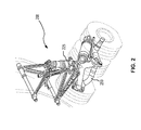
FIG. 2 illustrates various structures fabricated using a pressure welding system in accordance with various embodiments; -
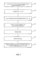
FIG. 3 illustrates a flow diagram in of a pressure welding system in accordance with various embodiments; and -
FIGS. 4A-4B illustrate a burner ring in accordance with various embodiments. - The detailed description of exemplary embodiments herein makes reference to the accompanying drawings, which show exemplary embodiments by way of illustration and their best mode. While these exemplary embodiments are described in sufficient detail to enable those skilled in the art to practice the inventions, it should be understood that other embodiments may be realized and that logical, chemical and mechanical changes may be made without departing from the scope of the disclosure. Thus, the detailed description herein is presented for purposes of illustration only and not of limitation. For example, the steps recited in any of the method or process descriptions may be executed in any order and are not necessarily limited to the order presented.
- Furthermore, any reference to singular includes plural embodiments, and any reference to more than one component or step may include a singular embodiment or step. Also, any reference to attached, fixed, connected or the like may include permanent, removable, temporary, partial, full and/or any other possible attachment option. Additionally, any reference to without contact (or similar phrases) may also include reduced contact or minimal contact. As used herein, phrases such as "make contact with," "coupled to," "touch," "interface with" and "engage" may be used interchangeably. The term welding may include the joining of metals by the application of heat and/or pressure, with or without the addition of a similar metal, such as a filler metal. A welding technique may be designated according to the purpose for which it is used, or the procedure employed, or the nature of the heat source. Some examples include gas welding, electrical-resistance welding, arc welding, and welding based on chemical reactions. As to the nature of the welding process itself, a distinction may be made between pressure welding and fusion welding. Additionally, gas pressure welding may be a distinct class of welding.
- A weld occurs when pieces of metal are joined by causing the interface to bond via diffusion or solidification as a uniform metal joint. This process may be caused by heat, pressure or a combination of both. When heat alone is used the process is called fusion welding. Pressure welding usually involves heating the surfaces of a pair of parts to a plastic state and then forcing the parts together. In pressure welding, the parts to be joined are first put under pressure and then locally heated at the place where the joint is to be formed. In response to being in a plastic state at the joint location, the parts are then deformed under force, so they may be united. Filler metal may be employed, but the use of a filler metal is not common.
- In gas pressure welding, the parts to be joined are mated by the exertion of substantially continuous pressure or impact type pressure and are then heated by a gas-and-oxygen mixture fuel source to and ignited to a flame. The gas in a gas-and-oxygen mixture may include a flammable gas such as a hydrocarbon gas. The flammable gas acts as a fuel source that bums in the presence of oxygen. For example, acetylene may be used in the gas-and-oxygen mixture as the fuel source.
- Acetylene (C2H2) is a colorless, highly flammable gas. Acetylene (systematic name: ethyne) is the simplest alkyne hydrocarbon, consisting of two hydrogen atoms and two carbon atoms connected by a triple bond. Combustion of acetylene with oxygen may produce a flame of over 3300°C (5972°F). Acetylene has long been used as a fuel source for welding applications; however, at times, acetylene may be unstable for high pressure welding applications. For example, the use of acetylene may lead to a backfire. A backfire is the loud popping noise that occurs when a welding or cutting torch flame bums back into the torch tip and is extinguished. Backfires may be caused by improper gas pressures, the torch tip touching the work to molten metal, an incorrectly installed tip, a loose tip, overheated tip, and/or the presence of impurities or other contamination of elements of the welding system.
- Propylene may be used as an alternative to welding with acetylene. However, it has been a long held understanding in the welding community that, while cutting may be performed using propylene, it is undesirable for use in welding. In welding, acetylene provides shielding due to the secondary reaction in the acetylene flame consuming oxygen in the atmosphere surrounding the weld. Propylene does not provide this shielding effect. The result has generally been a poor quality weld, such as one with porosity. Porosity is weld metal contamination in the form of a trapped gas. Shielding gases or gases released as a result of the torch being applied to treated metal are absorbed into the molten metal and released as solidification takes place. In other instances, the shielding gas does not completely reach the weld pool and the atmospheric air adversely affects the weld bead.
- Controlling the pressure of the gases and the conditions of the burner ring may reduce instances of porosity in the weld. A gas pressure welding system as disclosed herein overcomes these historical concerns and utilizes propylene as the fuel source in its gas-and-oxygen mixture. Stated another way, the gas flows described herein and/or the ratio of gas to oxygen described herein and/or the combination of the two overcome the historical concerns of utilizing propylene as the fuel source in its gas-and-oxygen mixture.
- Propylene (C3H6) (IUPAC name: propene) gas is a colorless, flammable gas characterized by a faintly sweet odor. Propylene is generally commercially available as a liquefied gas. Propylene gas in the gas-and-oxygen mixture has high heat release in its primary and secondary flames. The heat release in the primary flame cone is similar to acetylene. The British thermal unit ("BTU") capacity of the outer flame fueled by propylene is superior to that of acetylene. Propylene gas in the gas-and-oxygen mixture combines the qualities of an acetylene flame with the secondary heating capacity of propane. Propylene burns hotter than propane. Propylene costs less and is much more stable than acetylene.
- According to various embodiments, with reference to
Figure 1 , awelding system 100 may comprise a gas supply, such as apropylene gas supply 110, and anoxygen supply 120. These gas supplies (propylene gas supply 110 and oxygen supply 120) may be coupled to aburner 150 viagas supply lines Burner 150 may mix the propylene gas and the oxygen gas into a gas-and-oxygen fuel source.Burner 150 may be a hand held burner and/or a semi-fixed position burner.Burner 150 may be moved by a worker and/or the movements ofburner 150 may be mechanized and controlled by a control system (not shown).Burner 150 may comprise aburner ring 160 as further described below (seeFIGS. 4A-4B ).Welding system 100 may further comprise a firstforce application device 170 and a secondforce application device 180 to direct force on materials being welded together. - First
force application device 170 and secondforce application device 180 may take on any desired shape or structure. Firstforce application device 170 and secondforce application device 180 may be suitably robust to handle to high heat of the gas pressure welding process. For instance, though not directly in the path of the flame, the materials of firstforce application device 170 and secondforce application device 180 will generally resist deformation due to heat of the gas pressure welding process. Firstforce application device 170 and secondforce application device 180 generally hold afirst part 177 and asecond part 187 respectively, in place during the gas pressure welding process. Firstforce application device 170 may comprise a retainingmember 175 for retainingfirst part 177 in firstforce application device 170. Similarly, secondforce application device 180 may comprise a retainingmember 185 for retaining asecond part 187 in secondforce application device 180. - Too much oxygen or too much propylene in the gas-and-oxygen mixture will typically affect the quality of the flame. For instance, an oxidizing flame may result if too much oxygen is used in the gas-and-oxygen mixture, while a reducing flame may result if excess gas is incorporated into the gas-and-oxygen mixture. A neutral flame is the result of a proper gas-and-oxygen mixture
- Optimal settings are found to provide enhanced performance of
welding system 100. According to various embodiments,welding system 100 may be operated using a ratio of oxygen to propylene gas of between 1.5 and 3, and more particularly, about 1.6, about 2.5, and about 2.7. For instance, a ratio of oxygen gas to propylene gas in the propylene-and-oxygen gas mixture is between about 2.4 and 2.5, and more specifically the ratio of oxygen gas to propylene gas in the propylene-and-oxygen gas mixture is between about 2.43 and 2.46 (e.g. the ratio of oxygen to propylene gas may be about 2.4343). According to various embodiments, the ratio of oxygen to propylene gas may be about 2.46. The total flow rate of oxygen-and-propylene mixture may be between 650 and 850 standard cubic feet per hour (SCFH) (5.1x10⁻³ and 6.33x10⁻³M3/s), such as about 675 SCFH (4.92x10⁻³m3/s), about 700 SCFH (5.51x10⁻³m3/s), and about 710 SCFH (5.58x10⁻³m3/s). For instance, the total flow rate of oxygen-and-propylene mixture may be about 704.8 standard cubic feet per hour (5.54x10⁻³m3/s). The total flow rate of oxygen-and-propylene mixture may be about 705 standard cubic feet per hour (5.54x10⁻³m3/s). Valves ofwelding system 100 may assist in controlling the total flow rate. For instance,valves supply lines burner 150 may control the total flow rate and/or a flow ratio. The total weld time may be between 300 and 630 seconds, such as about 313 seconds, about 438 seconds and about 599 seconds. - The rate of load decrease of
welding system 100, may be between about 1300 and 1600 pounds/second (about 589.7 and 725.7 kilograms/second). For instance, the rate of load decrease (e.g. load slope down) may be about 1325 pounds/second (about 601 kilograms/second). The rate of load decrease may be about 1525 pounds/second (about 691.7 kilograms/second). A shift point, (e.g. the time to apply a load) may be ay any desired interval; however, in various embodiments the shift point is between about 60 and 120 seconds. The shift point may occur at about 80 seconds. Total flow rate and/or ratio of oxygen to propylene gas may carry more weight than the timing of the shift point and/or the rate of load decrease. Stated another way, total flow rate and/or ratio of oxygen to propylene gas may be factors that influence the quality of the bond as compared with the rate of load decrease and/or shift point. The distance to apply the load may be about .9 inches (about 2.286 centimeters). -
Welding system 100 may be used to weld two parts together. The parts may be any suitable parts. For instance, the parts welded by weldingsystem 100 via an oxygen-and-propylene gas mixture may be a structural part of a vehicle, an aspect of a tool and/or the like. According to various embodiments,welding system 100 may be used to produce aircraft parts. For instance, the aircraft may be a commercial aircraft and/or a military aircraft such as a military transport aircraft. Specifically with reference toFigure 2 , thelanding gear 200 and its elements are shown. A middle landing gear component of a military transport aircraft may be fabricated in part utilizingwelding system 100. For instance, two parts may be welded together to formpost 225.Landing gear post 225 may be made from any suitable material. According to various embodiments,landing gear post 225 is made of steel. A completedlanding gear post 225 is generally tubular in shape.Landing gear post 225 may be coupled to an upper cross shaft and a lower cross shaft oflanding gear 200.Landing gear post 225 may be coupled toaxle beam 250. - According to various embodiments, the
axle beam 250 may be fabricated in part utilizingwelding system 100. For instance, parts may be welded together to formaxle beam 250 usingwelding system 100.Axle beam 250 may be made from any suitable material. According to various embodiments,axle beam 250 is made of steel. A completed axle beam 250 (e.g. welded from two parts) is generally tubular in shape with a slight bend from its distal to proximal end. The bend is generally less than 90 degrees.Axle beam 250 may couple to the axel oflanding gear 200 which retains the wheel. - According to various embodiments, a weld may be made by welding
system 100 comprising a total gas flow of about 705 cubic feet (about 19,963 liters) per hour (5.5 5x10⁻³m3/s) . The oxygen to propylene ratio may be about 2.43. The gas flow of the oxygen and propylene mixture may be applied substantially continuously. The dynamic pressure of the propylene gas of the oxygen and propylene mixture may be between 29 and 31 pound-force per square inch (PSIG) (about 199,947.96 pascals and 213,737.47 pascals). The flow of the propylene gas from thegas supply 110 may be about 206 cubic feet per hour (1.62x10⁻³m3/s). - For instance, a flow rate of the propylene gas may be between about 195 and 215 CFH (1.53x10⁻³ and 1.69x10⁻³m3/s). A flow rate of the oxygen gas may be between about 485 and 510 CFH (3.81x10⁻³ and 4.01x10⁻³m3/s). The dynamic pressure of the oxygen gas of the oxygen and propylene mixture may be between 29 and 31 (PSIG) (199,947.96 pascals and 213,737.47 pascals). The flow of the propylene gas from the
gas supply 120 may be about 499 cubic feet (about 14,130 liters) per hour (3.92x10⁻³m3/s). - According to various embodiments and with reference to
Figure 3 , process for welding two parts, such as two parts ofpost 225 and/oraxle beam 250, may comprise loading at least twoparts force application device 170 and second force application device 180 (step 305). The process may include preheating one ormore parts post 225 and/or axle beam 250 (step 310). The preheating may be at a temperature of about 1150 degrees Fahrenheit (about 621.1 degree Celsius) for about 2 hours.Parts member 175 and retainingmember 185.Parts burner 150 fueled by gas-and-oxygen fuel source (step 320). The gas-and-oxygen mixture may be an oxygen-and-propylene mixture.Parts force application device 170 and/or secondforce application device 180 at any time, such as prior to preheating, intermittently, substantially constantly, during pre-heating, prior to introduction to welding temperature heat, during welding temperature heat, and/or after welding temperature heat is reduced and/or removed (step 315). The high heat may be ceased (step 325). The application of pressure may end at any suitable time (step 330). - According to various embodiments, the process may include austentizing and/or quenching
parts parts Parts parts members - According to various embodiments and with reference to
FIGS. 4A-4B , aburner ring 160 ofburner 150 may be used to direct high heat and toweld parts Burner ring 160 may be made from any suitable material. For instance,burner ring 160 may be abrass burner ring 160.Burner ring 160 may comprise a generally annular shape.Burner ring 160 may comprise a plurality ofoutlets 410 for oxygen gas and a secondary gas, such as propylene and/or the oxygen-and-propylene mixture to flow through.Outlets 410 may be located proximate the center ofburner ring 160. Beveled edges, seeangle 420, may flank theoutlets 410 so that contaminants from the welding process, such as any drippings, are directed away from theoutlets 410. This may help prevent backfires. -
Burner ring 160 may be formed from two half rings. These half rings may be secured together via clampingfixtures 466.Burner ring 160 may be mounted via mountingclips 450.Burner ring 160 may comprise at least oneinlet 440 for receiving the oxygen-and-propylene mixture.FIG. 4B depicts an inside portion ofburner ring 160 depicted inFIG. 4A along cut-plane "B".Burner ring 160 may further comprise abaffle 430. - In various embodiments, while the pressure welding using propylene as a fuel source system described herein have been described in the context of aircraft applications and the manufacture of aircraft parts, one will appreciate in light of the present disclosure, that its use may be applicable to other machinery and/or vehicles such as, trains.
- Benefits, other advantages, and solutions to problems have been described herein with regard to specific embodiments. Furthermore, the connecting lines shown in the various figures contained herein are intended to represent exemplary functional relationships and/or physical couplings between the various elements. It should be noted that many alternative or additional functional relationships or physical connections may be present in a practical system. However, the benefits, advantages, solutions to problems, and any elements that may cause any benefit, advantage, or solution to occur or become more pronounced are not to be construed as critical, required, or essential features or elements of the inventions. The scope of the inventions is accordingly to be limited by nothing other than the appended claims, in which reference to an element in the singular is not intended to mean "one and only one" unless explicitly so stated, but rather "one or more." Moreover, where a phrase similar to "at least one of A, B, or C" is used in the claims, it is intended that the phrase be interpreted to mean that A alone may be present in an embodiment, B alone may be present in an embodiment, C alone may be present in an embodiment, or that any combination of the elements A, B and C may be present in a single embodiment; for example, A and B, A and C, B and C, or A and B and C.
- Systems, methods and apparatus are provided herein. In the detailed description herein, references to "various embodiments", "one embodiment", "an embodiment", "an example embodiment", etc., indicate that the embodiment described may include a particular feature, structure, or characteristic, but every embodiment may not necessarily include the particular feature, structure, or characteristic. Moreover, such phrases are not necessarily referring to the same embodiment. Further, when a particular feature, structure, or characteristic is described in connection with an embodiment, it is submitted that it is within the knowledge of one skilled in the art to affect such feature, structure, or characteristic in connection with other embodiments whether or not explicitly described. After reading the description, it will be apparent to one skilled in the relevant art(s) how to implement the disclosure in alternative embodiments.
- Furthermore, no element, component, or method step in the present disclosure is intended to be dedicated to the public regardless of whether the element, component, or method step is explicitly recited in the claims. No claim element herein is to be construed under the provisions of 35 U.S.C. 112, sixth paragraph, unless the element is expressly recited using the phrase "means for." As used herein, the terms "comprises", "comprising", or any other variation thereof, are intended to cover a non-exclusive inclusion, such that a process, method, article, or apparatus that comprises a list of elements does not include only those elements but may include other elements not expressly listed or inherent to such process, method, article, or apparatus.
Claims (15)
- A process comprising:mixing propylene gas and oxygen gas to form a propylene-and-oxygen gas mixture, wherein the oxygen gas is supplied from an oxygen supply tank (120) to a burner unit (150), and wherein the propylene gas is supplied from a gas supply tank (110) to the burner unit (150); andigniting, by the burner unit (150), the propylene-and-oxygen mixture as a fuel source for a gas pressure welding apparatus to weld two parts (177,187) together, wherein a ratio of oxygen gas to propylene gas in the propylene-and-oxygen gas mixture is between about 2 and 3.
- The process of claim 1, wherein the two parts (177,187) form a component of a landing gear apparatus of an aircraft (200).
- The process of claim 1 or 2, further comprising applying force to the two parts (177,187) by a first force application device (170) and a second force application device (180).
- The process of claim 1 or 2, comprising:welding the two parts together, wherein welding the two parts together further comprises:loading the first part (177) in a first force application device (170);loading the second part (187) in a second force application device (180);preheating the first and second part;applying high heat to the first and second part (177,187) by the burner unit (150);applying high pressure to the first part (177) and the second part (187) by compressing the first and second force application devices (170,180) together; andwelding the first and second part (177, 187) together.
- A process of welding a component comprising;
loading a first portion of the component in a first force application device (170), loading a second portion of the component in a second force application device (180);
preheating the first portion and the second portion;
applying high heat to the first portion and the second portion by a burner unit (150), wherein the burner unit (150) is fueled by a propylene-and-oxygen gas mixture, wherein a ratio of oxygen gas to propylene gas in the propylene-and-oxygen gas mixture is between about 2.4 and 2.5;
applying high pressure to the first portion and the second portion by compressing the first force application device (170) and the second force application device (180) together; and
welding the first portion and the second portion into the component. - The process of claim 5, wherein the component is a part of a landing gear apparatus for an aircraft (200).
- The process of any preceding claim, wherein the component is at least one of a post (225) and an axle beam (250); or
wherein the two parts (177,187) are at least one of a post (225) and an axle beam (250). - The process of any preceding claim, wherein the burner unit (150) comprises an annular burner ring (160) comprising a beveled portion (420) configured to enable contaminants of the welding process to flow away from a propylene-and-oxygen gas mixture outlet of the burner unit (150).
- The process of any preceding claim, wherein a ratio of oxygen gas to propylene gas in the propylene-and-oxygen gas mixture is about 2.46.
- The process of any claims 1 to 8, wherein a ratio of oxygen gas to propylene gas in the propylene-and-oxygen gas mixture is between about 2.4 and 2.5.
- The process of any of claims 1 to 8, wherein a ratio of oxygen gas to propylene gas in the propylene-and-oxygen gas mixture is between about 2.43 and 2.46.
- The process of any preceding claim, wherein a flow rate of the propylene gas is between about 195 and 215 CFH (1.53x10⁻³ and 1.69x10⁻³m3/s).
- The process of any preceding claim, wherein a flow rate of the oxygen gas is between about 485 and 510 CFH (3.81x10⁻³ and 4.01x10⁻³m3/s).
- The process of any preceding claim, wherein a pressure dynamic of the supplied oxygen gas is between about 29 and 31 PSIG (199.94796 and 213.73747 kPa).
- The process of any preceding claim, wherein a pressure dynamic of the supplied propylene gas is between about 29 and 31 PSIG (199.94796 and 213.73747 kPa).
Applications Claiming Priority (1)
| Application Number | Priority Date | Filing Date | Title |
|---|---|---|---|
| US13/956,097 US9156102B2 (en) | 2013-07-31 | 2013-07-31 | Pressure welding using propylene |
Publications (3)
| Publication Number | Publication Date |
|---|---|
| EP2835205A2 true EP2835205A2 (en) | 2015-02-11 |
| EP2835205A3 EP2835205A3 (en) | 2015-11-04 |
| EP2835205B1 EP2835205B1 (en) | 2020-05-06 |
Family
ID=50842154
Family Applications (1)
| Application Number | Title | Priority Date | Filing Date |
|---|---|---|---|
| EP14170825.5A Active EP2835205B1 (en) | 2013-07-31 | 2014-06-02 | Pressure welding using propylene |
Country Status (2)
| Country | Link |
|---|---|
| US (1) | US9156102B2 (en) |
| EP (1) | EP2835205B1 (en) |
Family Cites Families (14)
| Publication number | Priority date | Publication date | Assignee | Title |
|---|---|---|---|---|
| US2499577A (en) * | 1946-08-23 | 1950-03-07 | Menasco Mfg Company | Method of inspecting welds |
| US2944449A (en) * | 1957-04-09 | 1960-07-12 | Menasco Mfg Company | Pressure welding apparatus |
| US2951750A (en) * | 1959-05-06 | 1960-09-06 | Samuel H White | Fuel gas mixture for metal working |
| DE2006185A1 (en) * | 1969-02-18 | 1970-10-01 | Air Products And Chemicals Inc., Philadelphia, Pa. (V.St.A.) | Gaseous fuel mixture |
| CH569077A5 (en) * | 1971-04-20 | 1975-11-14 | Linde Ag | |
| US3900297A (en) * | 1971-06-07 | 1975-08-19 | James Michaels | Fuel for engines |
| US3989479A (en) * | 1973-09-25 | 1976-11-02 | Anne Joffre White | Gaseous fuel mixture |
| KR950011312B1 (en) | 1990-10-05 | 1995-09-30 | 수미도모 메탈 인더스트리에스 리미티드 | Hot joining method of steel |
| US5979741A (en) * | 1996-11-28 | 1999-11-09 | Iguchi; Hirohito | Device for gas pressure welding |
| CA2404575C (en) * | 2002-09-23 | 2008-10-21 | Karel Bostik | Method of joining coiled sucker rod in the field |
| US7045172B2 (en) * | 2003-07-31 | 2006-05-16 | Praxair S.T. Technology, Inc. | Method of shielding effluents in spray devices |
| AU2007331010B2 (en) * | 2006-11-01 | 2011-10-27 | Bharat Petroleum Corporation Limited | Hydrocarbon fuel compositions |
| EP2640541A1 (en) * | 2010-11-19 | 2013-09-25 | Carrier Corporation | Method of and system for brazing aluminum workpieces using a flame and monitoring of the flame color |
| US8444041B2 (en) * | 2011-04-08 | 2013-05-21 | Lincoln Global, Inc. | Brazing system and method |
-
2013
- 2013-07-31 US US13/956,097 patent/US9156102B2/en active Active
-
2014
- 2014-06-02 EP EP14170825.5A patent/EP2835205B1/en active Active
Non-Patent Citations (1)
| Title |
|---|
| None |
Also Published As
| Publication number | Publication date |
|---|---|
| EP2835205B1 (en) | 2020-05-06 |
| EP2835205A3 (en) | 2015-11-04 |
| US20150034705A1 (en) | 2015-02-05 |
| US9156102B2 (en) | 2015-10-13 |
Similar Documents
| Publication | Publication Date | Title |
|---|---|---|
| US9322572B2 (en) | Environmentally friendly fuel gas within a refillable and non-corrosive gas cylinder | |
| EP2835205B1 (en) | Pressure welding using propylene | |
| EP4372070A2 (en) | Oxy fuel gas mixtures and methods for use | |
| Galvery et al. | Welding essentials: questions & answers | |
| CA2717194A1 (en) | Method and equipment for flame cutting a steel part | |
| US11724328B1 (en) | Multi-fuel adapter tactical system | |
| US20170089576A1 (en) | Torch ignition system and ignition assembly | |
| US1091479A (en) | Welding process. | |
| RU2571677C2 (en) | Torch for shielded gas welding | |
| US1520624A (en) | Process of burning liquid fuels | |
| KR102310325B1 (en) | Brazing method and apparatus for preventing surface oxidation | |
| JP6162377B2 (en) | Method of fusing flammable gas and steel | |
| JP4292091B2 (en) | Joined rebar and rebar joining method | |
| JP2017187260A (en) | Surface treatment method for galvanized steel and welding method for galvanized steel | |
| JP2001259862A (en) | Gas pressure welding method using non-reducing gas | |
| US2214031A (en) | Apparatus for joining metal members | |
| JP3380776B2 (en) | Gas pressure welding method to switch acetylene gas to another fuel gas in the middle | |
| JP4646323B2 (en) | Burner for liquefied petroleum gas | |
| JP4145411B2 (en) | Gas pressure welding method | |
| CN203036639U (en) | Welding gun | |
| CN111263708B (en) | Travel trolley | |
| JP4015380B2 (en) | Gas pressure welding method and gas pressure welding device | |
| Yamamoto | Advances in gas pressure welding technology for rails | |
| AU2019330472B2 (en) | An igniter | |
| WO2018078708A1 (en) | Catalyst metal fitting for burner, operation method, and hot air welding machine |
Legal Events
| Date | Code | Title | Description |
|---|---|---|---|
| PUAI | Public reference made under article 153(3) epc to a published international application that has entered the european phase |
Free format text: ORIGINAL CODE: 0009012 |
|
| 17P | Request for examination filed |
Effective date: 20140602 |
|
| AK | Designated contracting states |
Kind code of ref document: A2 Designated state(s): AL AT BE BG CH CY CZ DE DK EE ES FI FR GB GR HR HU IE IS IT LI LT LU LV MC MK MT NL NO PL PT RO RS SE SI SK SM TR |
|
| AX | Request for extension of the european patent |
Extension state: BA ME |
|
| PUAL | Search report despatched |
Free format text: ORIGINAL CODE: 0009013 |
|
| AK | Designated contracting states |
Kind code of ref document: A3 Designated state(s): AL AT BE BG CH CY CZ DE DK EE ES FI FR GB GR HR HU IE IS IT LI LT LU LV MC MK MT NL NO PL PT RO RS SE SI SK SM TR |
|
| AX | Request for extension of the european patent |
Extension state: BA ME |
|
| RIC1 | Information provided on ipc code assigned before grant |
Ipc: B23K 35/38 20060101ALI20150928BHEP Ipc: B64F 5/00 20060101ALI20150928BHEP Ipc: B23K 5/00 20060101AFI20150928BHEP |
|
| R17P | Request for examination filed (corrected) |
Effective date: 20160504 |
|
| RBV | Designated contracting states (corrected) |
Designated state(s): AL AT BE BG CH CY CZ DE DK EE ES FI FR GB GR HR HU IE IS IT LI LT LU LV MC MK MT NL NO PL PT RO RS SE SI SK SM TR |
|
| RIN1 | Information on inventor provided before grant (corrected) |
Inventor name: OVERMANN, JR., MARK Inventor name: MAITLAND, SCOTT |
|
| STAA | Information on the status of an ep patent application or granted ep patent |
Free format text: STATUS: REQUEST FOR EXAMINATION WAS MADE |
|
| R17P | Request for examination filed (corrected) |
Effective date: 20160504 |
|
| RIN1 | Information on inventor provided before grant (corrected) |
Inventor name: MAITLAND, SCOTT Inventor name: OVERMANN, JR., MARK |
|
| STAA | Information on the status of an ep patent application or granted ep patent |
Free format text: STATUS: EXAMINATION IS IN PROGRESS |
|
| 17Q | First examination report despatched |
Effective date: 20190513 |
|
| GRAP | Despatch of communication of intention to grant a patent |
Free format text: ORIGINAL CODE: EPIDOSNIGR1 |
|
| STAA | Information on the status of an ep patent application or granted ep patent |
Free format text: STATUS: GRANT OF PATENT IS INTENDED |
|
| INTG | Intention to grant announced |
Effective date: 20200225 |
|
| GRAS | Grant fee paid |
Free format text: ORIGINAL CODE: EPIDOSNIGR3 |
|
| GRAA | (expected) grant |
Free format text: ORIGINAL CODE: 0009210 |
|
| STAA | Information on the status of an ep patent application or granted ep patent |
Free format text: STATUS: THE PATENT HAS BEEN GRANTED |
|
| AK | Designated contracting states |
Kind code of ref document: B1 Designated state(s): AL AT BE BG CH CY CZ DE DK EE ES FI FR GB GR HR HU IE IS IT LI LT LU LV MC MK MT NL NO PL PT RO RS SE SI SK SM TR |
|
| REG | Reference to a national code |
Ref country code: GB Ref legal event code: FG4D |
|
| REG | Reference to a national code |
Ref country code: CH Ref legal event code: EP Ref country code: AT Ref legal event code: REF Ref document number: 1265997 Country of ref document: AT Kind code of ref document: T Effective date: 20200515 |
|
| REG | Reference to a national code |
Ref country code: IE Ref legal event code: FG4D |
|
| REG | Reference to a national code |
Ref country code: DE Ref legal event code: R096 Ref document number: 602014064840 Country of ref document: DE |
|
| REG | Reference to a national code |
Ref country code: LT Ref legal event code: MG4D |
|
| REG | Reference to a national code |
Ref country code: NL Ref legal event code: MP Effective date: 20200506 |
|
| PG25 | Lapsed in a contracting state [announced via postgrant information from national office to epo] |
Ref country code: SE Free format text: LAPSE BECAUSE OF FAILURE TO SUBMIT A TRANSLATION OF THE DESCRIPTION OR TO PAY THE FEE WITHIN THE PRESCRIBED TIME-LIMIT Effective date: 20200506 Ref country code: LT Free format text: LAPSE BECAUSE OF FAILURE TO SUBMIT A TRANSLATION OF THE DESCRIPTION OR TO PAY THE FEE WITHIN THE PRESCRIBED TIME-LIMIT Effective date: 20200506 Ref country code: PT Free format text: LAPSE BECAUSE OF FAILURE TO SUBMIT A TRANSLATION OF THE DESCRIPTION OR TO PAY THE FEE WITHIN THE PRESCRIBED TIME-LIMIT Effective date: 20200907 Ref country code: IS Free format text: LAPSE BECAUSE OF FAILURE TO SUBMIT A TRANSLATION OF THE DESCRIPTION OR TO PAY THE FEE WITHIN THE PRESCRIBED TIME-LIMIT Effective date: 20200906 Ref country code: NO Free format text: LAPSE BECAUSE OF FAILURE TO SUBMIT A TRANSLATION OF THE DESCRIPTION OR TO PAY THE FEE WITHIN THE PRESCRIBED TIME-LIMIT Effective date: 20200806 Ref country code: GR Free format text: LAPSE BECAUSE OF FAILURE TO SUBMIT A TRANSLATION OF THE DESCRIPTION OR TO PAY THE FEE WITHIN THE PRESCRIBED TIME-LIMIT Effective date: 20200807 Ref country code: FI Free format text: LAPSE BECAUSE OF FAILURE TO SUBMIT A TRANSLATION OF THE DESCRIPTION OR TO PAY THE FEE WITHIN THE PRESCRIBED TIME-LIMIT Effective date: 20200506 |
|
| PG25 | Lapsed in a contracting state [announced via postgrant information from national office to epo] |
Ref country code: LV Free format text: LAPSE BECAUSE OF FAILURE TO SUBMIT A TRANSLATION OF THE DESCRIPTION OR TO PAY THE FEE WITHIN THE PRESCRIBED TIME-LIMIT Effective date: 20200506 Ref country code: HR Free format text: LAPSE BECAUSE OF FAILURE TO SUBMIT A TRANSLATION OF THE DESCRIPTION OR TO PAY THE FEE WITHIN THE PRESCRIBED TIME-LIMIT Effective date: 20200506 Ref country code: BG Free format text: LAPSE BECAUSE OF FAILURE TO SUBMIT A TRANSLATION OF THE DESCRIPTION OR TO PAY THE FEE WITHIN THE PRESCRIBED TIME-LIMIT Effective date: 20200806 Ref country code: RS Free format text: LAPSE BECAUSE OF FAILURE TO SUBMIT A TRANSLATION OF THE DESCRIPTION OR TO PAY THE FEE WITHIN THE PRESCRIBED TIME-LIMIT Effective date: 20200506 |
|
| REG | Reference to a national code |
Ref country code: AT Ref legal event code: MK05 Ref document number: 1265997 Country of ref document: AT Kind code of ref document: T Effective date: 20200506 |
|
| PG25 | Lapsed in a contracting state [announced via postgrant information from national office to epo] |
Ref country code: NL Free format text: LAPSE BECAUSE OF FAILURE TO SUBMIT A TRANSLATION OF THE DESCRIPTION OR TO PAY THE FEE WITHIN THE PRESCRIBED TIME-LIMIT Effective date: 20200506 Ref country code: AL Free format text: LAPSE BECAUSE OF FAILURE TO SUBMIT A TRANSLATION OF THE DESCRIPTION OR TO PAY THE FEE WITHIN THE PRESCRIBED TIME-LIMIT Effective date: 20200506 |
|
| REG | Reference to a national code |
Ref country code: DE Ref legal event code: R119 Ref document number: 602014064840 Country of ref document: DE |
|
| PG25 | Lapsed in a contracting state [announced via postgrant information from national office to epo] |
Ref country code: IT Free format text: LAPSE BECAUSE OF FAILURE TO SUBMIT A TRANSLATION OF THE DESCRIPTION OR TO PAY THE FEE WITHIN THE PRESCRIBED TIME-LIMIT Effective date: 20200506 Ref country code: RO Free format text: LAPSE BECAUSE OF FAILURE TO SUBMIT A TRANSLATION OF THE DESCRIPTION OR TO PAY THE FEE WITHIN THE PRESCRIBED TIME-LIMIT Effective date: 20200506 Ref country code: CZ Free format text: LAPSE BECAUSE OF FAILURE TO SUBMIT A TRANSLATION OF THE DESCRIPTION OR TO PAY THE FEE WITHIN THE PRESCRIBED TIME-LIMIT Effective date: 20200506 Ref country code: ES Free format text: LAPSE BECAUSE OF FAILURE TO SUBMIT A TRANSLATION OF THE DESCRIPTION OR TO PAY THE FEE WITHIN THE PRESCRIBED TIME-LIMIT Effective date: 20200506 Ref country code: AT Free format text: LAPSE BECAUSE OF FAILURE TO SUBMIT A TRANSLATION OF THE DESCRIPTION OR TO PAY THE FEE WITHIN THE PRESCRIBED TIME-LIMIT Effective date: 20200506 Ref country code: SM Free format text: LAPSE BECAUSE OF FAILURE TO SUBMIT A TRANSLATION OF THE DESCRIPTION OR TO PAY THE FEE WITHIN THE PRESCRIBED TIME-LIMIT Effective date: 20200506 Ref country code: EE Free format text: LAPSE BECAUSE OF FAILURE TO SUBMIT A TRANSLATION OF THE DESCRIPTION OR TO PAY THE FEE WITHIN THE PRESCRIBED TIME-LIMIT Effective date: 20200506 Ref country code: DK Free format text: LAPSE BECAUSE OF FAILURE TO SUBMIT A TRANSLATION OF THE DESCRIPTION OR TO PAY THE FEE WITHIN THE PRESCRIBED TIME-LIMIT Effective date: 20200506 |
|
| REG | Reference to a national code |
Ref country code: CH Ref legal event code: PL |
|
| PG25 | Lapsed in a contracting state [announced via postgrant information from national office to epo] |
Ref country code: SK Free format text: LAPSE BECAUSE OF FAILURE TO SUBMIT A TRANSLATION OF THE DESCRIPTION OR TO PAY THE FEE WITHIN THE PRESCRIBED TIME-LIMIT Effective date: 20200506 Ref country code: MC Free format text: LAPSE BECAUSE OF FAILURE TO SUBMIT A TRANSLATION OF THE DESCRIPTION OR TO PAY THE FEE WITHIN THE PRESCRIBED TIME-LIMIT Effective date: 20200506 Ref country code: PL Free format text: LAPSE BECAUSE OF FAILURE TO SUBMIT A TRANSLATION OF THE DESCRIPTION OR TO PAY THE FEE WITHIN THE PRESCRIBED TIME-LIMIT Effective date: 20200506 |
|
| PLBE | No opposition filed within time limit |
Free format text: ORIGINAL CODE: 0009261 |
|
| STAA | Information on the status of an ep patent application or granted ep patent |
Free format text: STATUS: NO OPPOSITION FILED WITHIN TIME LIMIT |
|
| PG25 | Lapsed in a contracting state [announced via postgrant information from national office to epo] |
Ref country code: LU Free format text: LAPSE BECAUSE OF NON-PAYMENT OF DUE FEES Effective date: 20200602 |
|
| 26N | No opposition filed |
Effective date: 20210209 |
|
| REG | Reference to a national code |
Ref country code: BE Ref legal event code: MM Effective date: 20200630 |
|
| PG25 | Lapsed in a contracting state [announced via postgrant information from national office to epo] |
Ref country code: LI Free format text: LAPSE BECAUSE OF NON-PAYMENT OF DUE FEES Effective date: 20200630 Ref country code: IE Free format text: LAPSE BECAUSE OF NON-PAYMENT OF DUE FEES Effective date: 20200602 Ref country code: CH Free format text: LAPSE BECAUSE OF NON-PAYMENT OF DUE FEES Effective date: 20200630 |
|
| PG25 | Lapsed in a contracting state [announced via postgrant information from national office to epo] |
Ref country code: DE Free format text: LAPSE BECAUSE OF NON-PAYMENT OF DUE FEES Effective date: 20210101 Ref country code: BE Free format text: LAPSE BECAUSE OF NON-PAYMENT OF DUE FEES Effective date: 20200630 Ref country code: SI Free format text: LAPSE BECAUSE OF FAILURE TO SUBMIT A TRANSLATION OF THE DESCRIPTION OR TO PAY THE FEE WITHIN THE PRESCRIBED TIME-LIMIT Effective date: 20200506 |
|
| PG25 | Lapsed in a contracting state [announced via postgrant information from national office to epo] |
Ref country code: TR Free format text: LAPSE BECAUSE OF FAILURE TO SUBMIT A TRANSLATION OF THE DESCRIPTION OR TO PAY THE FEE WITHIN THE PRESCRIBED TIME-LIMIT Effective date: 20200506 Ref country code: MT Free format text: LAPSE BECAUSE OF FAILURE TO SUBMIT A TRANSLATION OF THE DESCRIPTION OR TO PAY THE FEE WITHIN THE PRESCRIBED TIME-LIMIT Effective date: 20200506 Ref country code: CY Free format text: LAPSE BECAUSE OF FAILURE TO SUBMIT A TRANSLATION OF THE DESCRIPTION OR TO PAY THE FEE WITHIN THE PRESCRIBED TIME-LIMIT Effective date: 20200506 |
|
| PG25 | Lapsed in a contracting state [announced via postgrant information from national office to epo] |
Ref country code: MK Free format text: LAPSE BECAUSE OF FAILURE TO SUBMIT A TRANSLATION OF THE DESCRIPTION OR TO PAY THE FEE WITHIN THE PRESCRIBED TIME-LIMIT Effective date: 20200506 |
|
| P01 | Opt-out of the competence of the unified patent court (upc) registered |
Effective date: 20230522 |
|
| PGFP | Annual fee paid to national office [announced via postgrant information from national office to epo] |
Ref country code: GB Payment date: 20250520 Year of fee payment: 12 |
|
| PGFP | Annual fee paid to national office [announced via postgrant information from national office to epo] |
Ref country code: FR Payment date: 20250520 Year of fee payment: 12 |