EP2835149A1 - Collimator for neutron capture therapy and neutron capture therapy apparatus - Google Patents
Collimator for neutron capture therapy and neutron capture therapy apparatus Download PDFInfo
- Publication number
- EP2835149A1 EP2835149A1 EP13769074.9A EP13769074A EP2835149A1 EP 2835149 A1 EP2835149 A1 EP 2835149A1 EP 13769074 A EP13769074 A EP 13769074A EP 2835149 A1 EP2835149 A1 EP 2835149A1
- Authority
- EP
- European Patent Office
- Prior art keywords
- collimator
- irradiation
- neutron
- leaf plates
- capture therapy
- Prior art date
- Legal status (The legal status is an assumption and is not a legal conclusion. Google has not performed a legal analysis and makes no representation as to the accuracy of the status listed.)
- Granted
Links
Images


Classifications
-
- A—HUMAN NECESSITIES
- A61—MEDICAL OR VETERINARY SCIENCE; HYGIENE
- A61N—ELECTROTHERAPY; MAGNETOTHERAPY; RADIATION THERAPY; ULTRASOUND THERAPY
- A61N5/00—Radiation therapy
- A61N5/10—X-ray therapy; Gamma-ray therapy; Particle-irradiation therapy
- A61N5/1042—X-ray therapy; Gamma-ray therapy; Particle-irradiation therapy with spatial modulation of the radiation beam within the treatment head
- A61N5/1045—X-ray therapy; Gamma-ray therapy; Particle-irradiation therapy with spatial modulation of the radiation beam within the treatment head using a multi-leaf collimator, e.g. for intensity modulated radiation therapy or IMRT
-
- G—PHYSICS
- G21—NUCLEAR PHYSICS; NUCLEAR ENGINEERING
- G21K—HANDLING OF PARTICLES OR IONISING RADIATION NOT OTHERWISE PROVIDED FOR; IRRADIATION DEVICES; GAMMA RAY OR X-RAY MICROSCOPES
- G21K1/00—Arrangements for handling particles or ionising radiation, e.g. focusing or moderating
- G21K1/02—Arrangements for handling particles or ionising radiation, e.g. focusing or moderating using diaphragms, collimators
- G21K1/04—Arrangements for handling particles or ionising radiation, e.g. focusing or moderating using diaphragms, collimators using variable diaphragms, shutters, choppers
- G21K1/046—Arrangements for handling particles or ionising radiation, e.g. focusing or moderating using diaphragms, collimators using variable diaphragms, shutters, choppers varying the contour of the field, e.g. multileaf collimators
-
- A—HUMAN NECESSITIES
- A61—MEDICAL OR VETERINARY SCIENCE; HYGIENE
- A61N—ELECTROTHERAPY; MAGNETOTHERAPY; RADIATION THERAPY; ULTRASOUND THERAPY
- A61N5/00—Radiation therapy
- A61N5/10—X-ray therapy; Gamma-ray therapy; Particle-irradiation therapy
- A61N2005/1085—X-ray therapy; Gamma-ray therapy; Particle-irradiation therapy characterised by the type of particles applied to the patient
- A61N2005/109—Neutrons
-
- A—HUMAN NECESSITIES
- A61—MEDICAL OR VETERINARY SCIENCE; HYGIENE
- A61N—ELECTROTHERAPY; MAGNETOTHERAPY; RADIATION THERAPY; ULTRASOUND THERAPY
- A61N5/00—Radiation therapy
- A61N5/10—X-ray therapy; Gamma-ray therapy; Particle-irradiation therapy
- A61N2005/1092—Details
- A61N2005/1095—Elements inserted into the radiation path within the system, e.g. filters or wedges
Definitions
- the present invention relates to a collimator for neutron capture therapy and a neutron capture therapy apparatus.
- a neutron beam irradiation apparatus which irradiates an affected area in the body of a patient with a neutron beam is known.
- a neutron beam is generated by irradiating a target with an ion beam (a charged particle beam) and the generated neutron beam is decelerated by a deceleration device and then emitted toward the patient.
- This apparatus has a collimator disposed between the deceleration device and the patient.
- the collimator is a rectangular parallelepiped-shaped member made of a lithium fluoride-containing polyethylene material and a neutron extraction port having a predetermined size is provided at the center thereof.
- the size of the neutron extraction port is formed in accordance with the shape of an irradiation range for each patient.
- the neutrons emitted from the deceleration device pass through the neutron extraction port of the collimator, thereby being shaped to a predetermined irradiation range.
- ⁇ rays a He beam
- Li beam a Li beam which are heavy charged particle beams
- cells of the affected area are destroyed by the particle beams.
- a placement stand on which a patient is put and the collimator are provided so as to be movable along a neutron extraction direction. Due to such a configuration, alignment of the neutron extraction port of the collimator with an irradiation target is easily performed, and thus improvement in irradiation accuracy is attained.
- a therapeutic method described above is called neutron capture therapy (NCT; Neutron Capture Therapy).
- NCT neutron capture therapy
- a neutron dose of neutrons which are irradiated to an affected area is predetermined before the start of treatment.
- a certain gap occurs between the rectangular parallelepiped-shaped collimator and the patient.
- the neutrons having passed through the collimator are dispersed before reaching the body surface of the patient.
- a neutron dose which is irradiated to tissues other than the affected area increases.
- a neutron dose which is irradiated to the affected area per hour becomes insufficient, and thus it takes a longer time to irradiate a predetermined neutron dose to the affected area.
- the present invention has an object to provide a collimator for neutron capture therapy and a neutron capture therapy apparatus, in which a neutron dose which is irradiated to an affected area per hour is secured, and thus it is possible to shorten irradiation time.
- a collimator for neutron capture therapy which sets an irradiation range of a neutron beam in accordance with an irradiation target in an irradiated body, including: a plurality of leaf plates stacked in a first direction orthogonal to an irradiation direction of the neutron beam, wherein at least some leaf plates among the plurality of leaf plates are configured to be slidable along a second direction orthogonal to the irradiation direction and orthogonal to the first direction and also slidable in the irradiation direction.
- the collimator for neutron capture therapy since at least some leaf plates among the plurality of leaf plates are slidable along the second direction orthogonal to the irradiation direction, it is possible to accurately set the irradiation range with respect to the irradiation target.
- at least some leaf plates are also slidable in the irradiation direction, it is possible to bring marginal edges of the leaf plates close to the surface of the irradiated body so as to conform to the shape of an irradiation site of the irradiated body. A gap between the collimator and the irradiated body is narrowed thereby, and thus dispersion of neutrons is suppressed. As a result, a neutron dose which is irradiated to the affected area per hour is secured, and thus it is possible to shorten irradiation time.
- At least some leaf plates may have a plurality of separate leaf plates divided in the second direction and the plurality of separate leaf plates may be configured to be respectively independently slidable in the irradiation direction.
- the plurality of separate leaf plates may be configured to be respectively independently slidable in the irradiation direction.
- the irradiation site of the irradiated body is rounded over the second direction, by sliding the respective separate leaves in the irradiation direction, it is possible to bring the marginal edges of the leaf plates close to the surface of the irradiation site. Dispersion of neutrons is even further suppressed thereby.
- a collimator for neutron capture therapy which sets an irradiation range of a neutron beam in accordance with an irradiation target in an irradiated body, including: a plurality of leaf plates which are stacked in a first direction orthogonal to an irradiation direction of the neutron beam and in which at least some of the plurality of leaf plates are divided into at least four separate leaf plates in a second direction orthogonal to the irradiation direction and the first direction; a support portion in the second direction which is configured to support the leaf plate so as to be slidable along the second direction; and a support portion in the irradiation direction which is configured to support an inner separate leaf plate of the separate leaf plates divided in the second direction so as to be slidable along the irradiation direction.
- the inner separate leaf plate is also slidable in the irradiation direction, it is possible to bring the marginal edges of the leaf plates close to the surface of the irradiated body so as to conform to the shape of the irradiation site of the irradiated body.
- a gap between the collimator and the irradiated body is narrowed thereby, and thus dispersion of neutrons is suppressed.
- a neutron dose which is irradiated to the affected area per hour is secured, and thus it is possible to shorten irradiation time.
- the support portion in the irradiation direction may be a locking portion which is provided at the separate leaf plate adjacent to the separate leaf plate supported so as to be slidable along the irradiation direction and is configured to lock an end portion of the separate leaf plate supported so as to be slidable along the irradiation direction.
- a neutron capture therapy apparatus including: a neutron beam generation section which is configured to generate a neutron beam; the above-described collimator for neutron capture therapy; and a collimator supporting section which is configured to support the collimator for neutron capture therapy.
- a neutron dose which is irradiated to an affected area per hour is secured, and thus it is possible to shorten irradiation time.
- a neutron beam irradiation apparatus 1 is a neutron capture therapy apparatus for irradiating an affected area (an irradiation target) T of a patient (an irradiated body) P with a neutron beam.
- the neutron beam irradiation apparatus 1 is an apparatus for boron neutron capture therapy (BNCT; Boron Neutron Capture Therapy) which selectively destroys cells of the affected area T by a nuclear reaction of a neutron with boron (10B) incorporated as a compound into the affected area T in advance.
- BNCT Boron Neutron Capture Therapy
- the neutron beam irradiation apparatus 1 is provided with a movable stand 2 on which the patient P is placed, a deceleration device 3 which decelerates neutrons, a target (a neutron beam generation section) 7 which generates neutrons, and a collimator stand (a collimator supporting section) 4 provided between the movable stand 2 and the deceleration device 3. Further, the neutron beam irradiation apparatus 1 is provided with a CR system 8 for imaging an X-ray image of the affected area T of the patient P.
- the movable stand 2 has a placement stand 2a on which the patient P sits down.
- the placement stand 2a is configured such that the patient P can also lie down thereon by changing the shape thereof.
- the movable stand 2 is made so as to be movable in an up-and-down direction (a vertical direction), a left-right direction (a horizontal direction, a direction approaching or being separated from the deceleration device 3), and a front-back direction (a horizontal direction, a direction perpendicular to the left-right direction).
- the target 7 generates neutrons by irradiating an ion beam (for example, a proton beam) emitted from an accelerator (not shown) thereto.
- the deceleration device 3 decelerates neutrons generated by the target 7.
- the neutrons decelerated by the deceleration device 3 are emitted to the patient P side.
- a shielding wall W is configured by concrete or the like and prevents unnecessary radiation irradiation to the patient P or the outside of a treatment room.
- a tip portion 3a of the deceleration device 3 passes through the shielding wall W.
- the collimator stand 4 moves, thereby approaching the deceleration device 3, whereby the tip portion 3a can enter into the back side of the collimator stand 4.
- a "back side" is the upstream side of the ion beam and a "front side” is the patient P side.
- a collimator (a collimator for neutron capture therapy) 6 is provided to protrude to the movable stand 2 side.
- the collimator 6 is for shaping the neutrons emitted from the deceleration device 3 into a predetermined shape (an irradiation range) and extracting the neutrons in an irradiation direction Y.
- the collimator stand 4 is made so as to be movable in the front-back direction.
- a concave portion receiving the tip portion 3a of the deceleration device 3 is formed.
- the collimator stand 4 is used in a state where the tip portion 3a has entered into the concave portion on the back side.
- the placement stand 2a with the patient P placed thereon is brought close to the front side of the collimator stand 4, whereby the collimator 6 is disposed so as to face the affected area T of the patient P.
- the collimator 6 sets an irradiation field F which is an irradiation range of a neutron beam, in accordance with the domain of the affected area T of the patient P.
- the collimator 6 has an outer shape of a rectangular parallelepiped shape.
- the collimator 6 has a plurality of leaf plates 13A and 13B stacked in an up-and-down direction (a first direction) Z orthogonal to the irradiation direction Y.
- the plurality of leaf plates 13A and 13B are arranged along a plate thickness direction thereof.
- the plurality of leaf plates 13A and 13B may be arranged along a left-right direction X.
- Each of the leaf plates 13A and 13B is made of lithium fluoride-containing polyethylene and has a rectangular plate shape.
- the plurality of leaf plates 13A and 13B are retained in a collimator holder 11, thereby configuring a leaf plate group 13.
- a guide member (a support portion in a second direction) 12 having a plurality of projections 16 for guiding the leaf plates 13A and 13B is disposed between the collimator holder 11 and the leaf plate group 13.
- An end portion in the irradiation direction Y of each of the leaf plates 13A and 13B, which comes into contact with the guide member 12, has a concavo-convex shape capable of being fitted to the projection 16 of the guide member 12.
- each of the leaf plates 13A (in the example of Fig. 3 , four for each of the top and the bottom) disposed at an upper end portion and a lower end portion of the leaf plate group 13 is a plate material divided into two in the left-right direction X.
- Each of the leaf plates 13B disposed at an intermediate portion excluding the upper end portion and the lower end portion of the leaf plate group 13 is configured by two separate leaf plates 14 and 15 per one side divided in the left-right direction (the second direction) X. More specifically, the separate leaf plate 14 and the separate leaf plate 15 are provided side by side in the left-right direction X.
- the separate leaf plate 14 is disposed outside (that is, near the collimator holder 11), and the separate leaf plate 15 is disposed inside (that is, near the irradiation field F) adjacent to the separate leaf plate 14.
- the separate leaf plate 14 and the separate leaf plate 15 are made so as to be slidable in the left-right direction X in an integrated manner. In this manner, the leaf plate 13B is slidable in the left-right direction X, and therefore, it is possible to arbitrarily set the shape and the size of the irradiation field F.
- the leaf plate 13A is not limited to a case of being divided into two in the left-right direction X and may be divided into, for example, four.
- the separate leaf plate 15 of the leaf plate 13B is also made so as to be slidable in the irradiation direction Y.
- a protruding portion 17 protruding in the left-right direction X and also extending in the irradiation direction Y is formed on the end face of the separate leaf plate 15, which comes into contact with the separate leaf plate 14.
- a groove portion (a support portion in the irradiation direction) 18 extending in the irradiation direction Y direction is formed in the end face of the separate leaf plate 14, which comes into contact with the separate leaf plate 15.
- the separate leaf plate 14 and the separate leaf plate 15 are respectively made so as to be slidable in the irradiation direction Y in a state where the protruding portion 17 is fitted into the groove portion 18.
- the groove portion 18 may also function as a locking portion which locks an end portion of the separate leaf plate 15 supported so as to be slidable in the irradiation direction Y.
- the collimator 6 having the above-described configuration is a 2-axis slide type multileaf collimator slidable in the left-right direction X and the irradiation direction Y.
- the collimator 6 it is possible to freely change the outer shape of the leaf plate group 13 in the left-right direction X and the irradiation direction Y.
- the shape of an irradiation site is examined in advance and the position of each of the leaf plates 13A and 13B is adjusted so as to conform to the shape.
- the position of each of the leaf plates 13A and 13B is manually adjusted by a handler.
- an irradiation site of the patient P is brought close to the collimator 6 in which the position adjustment has been completed, and a neutron beam is irradiated toward the affected area T with a predetermined neutron dose.
- the plurality of leaf plates 13B are slidable along the left-right direction X orthogonal to the irradiation direction Y, and therefore, it is possible to accurately set the irradiation field F with respect to the affected area T.
- the separate leaf plate 15 of the leaf plate 13B is also slidable in the irradiation direction Y, and therefore, it is possible to bring a marginal edge of the separate leaf plate 15 close to a body surface Pa of the patient P so as to conform to the shape of the irradiation site.
- a gap between the collimator 6 and the patient P is narrowed thereby, and thus dispersion of neutrons is suppressed.
- a neutron dose which is irradiated to the affected area T per hour is secured, and thus it is possible to shorten irradiation time. This also contributes to a reduction in the burden on the patient P at the time of treatment.
- a neutron has a property of being relatively easily dispersed.
- a collimator of the related art since it is not possible to change an outer shape, it is difficult to make an end face of the collimator be fitted according to the shape of an irradiation site.
- a gap between the body surface Pa of the patient P and the leaf plates 13A and 13B is made as small as possible, and thus it is possible to block dispersion of neutrons. In this way, it is possible to attain the optimization of a neutron dose.
- the plurality of separate leaf plates 15 of the leaf plates 13B are respectively independently slidable in the irradiation direction Y, and therefore, for example, even in a case where the irradiation site of the patient P is rounded over the left-right direction X, by sliding the respective separate leaves 14 and 15 in the irradiation direction Y, it is possible to bring the marginal edges of the leaf plates 14 and 15 close to the body surface Pa of the irradiation site (refer to Fig. 4 ). Dispersion of neutrons is even further suppressed thereby.
- Fig. 5(a) is a cross-sectional view of a collimator according to another embodiment
- Fig. 5(b) is a cross-sectional view of a collimator of the related art.
- a leaf plate 23 of a collimator 20 shown in Fig. 5 (a) is different from the leaf plate 13B of the collimator 6 shown in Fig. 3 in that the leaf plate 23 is provided with separate leaf plates 24, 25, and 26 configured so as to be three pieces with respect to one side and that inner corner portions on the side opposite to the patient P of the respective separate leaf plates 24 to 26 are cut out, whereby tapered portions 24a to 26a are formed at the respective separate leaf plates 24 to 26.
- the separate leaf plates 25 and 26 with the exception of the separate leaf plate 24 are made so as to be slidable in the irradiation direction Y.
- Fig. 5 (a) due to the points that the respective separate leaf plates 24 to 26 have the tapered portions 24a to 26a and that the separate leaf plates 25 and 26 slide in the irradiation direction Y, it is possible to make a direction in which neutrons are incident wider as a whole.
- a neutron beam is irradiated to the affected area T (for example, a tumor) which is present in a neck portion G of the patient P is shown.
- the neck portion G of the patient P is present between a jaw portion H and a shoulder portion E.
- the separate leaf plates 25 and 26 slide so as to come into close contact with the body surface Pa of the patient P, whereby it is possible to prevent the dispersion of neutrons from a gap between a body surface and the collimator 20. Due to the effects, high-dose-rate irradiation becomes possible, and thus the shortening of irradiation time is attained. Furthermore, due to having a tapered structure obliquely cut on the neutron incidence side, it is possible to widen a direction of incident neutrons, and thus it is possible to use a lot of neutrons capable of contributing to the irradiation to the affected area T.
- the basic role of a collimator is for cutting radiation outside an irradiated area, thereby making exposure of normal tissue be less than or equal to a negligible amount.
- Radiation therapy for example, X-ray therapy or proton therapy
- Radiation therapy basically collimates radiation which is emitted from one point and goes straight ahead, in accordance with an irradiated area, and a flat plate-shaped collimator is set at a place distant by several cm from an irradiation body surface.
- neutrons most thereof become scattered radiation even in an atomic reactor or even in an accelerator and neutrons arriving in a direction of a collimator from a very large area compared to the collimator are used.
- the separate leaf plates are not limited to two or three and there may be four or more.
- the separate leaf plates it is possible to make the separate leaf plates other than the separate leaf plates on the outermost side (the collimator holder 11 side in the left-right direction X) be slidable in the irradiation direction Y.
- only the separate leaf plates on the innermost side (the irradiation field F side) may be made to be slidable in the irradiation direction Y.
- a drive mechanism connected to each of the separate leaf plates 14 and 15 of the leaf plate 13A and the leaf plate 13B may be provided.
- the drive mechanism for example, a roller and a motor, or a piston or the like can be used. Due to the drive mechanism, it is possible to automate the movement and the positioning of the leaf plates 13A and 13B.
- the support portion in the irradiation direction may be 14 provided at the separate leaf plate 14 and a support mechanism may be provided as a separate member at an end portion of the separate leaf plate 14.
- the collimator stand 4 may not be provided independently, and a portion supporting the collimator may be provided at, for example, the shielding wall W or the deceleration device 3.
- the present invention is not limited to BNCT using a boron compound and may be applied to NCT using other elements.
- the present invention can also be applied as a collimator which is used in a therapeutic method using a nuclear reaction of a neutron with gadolinium (157Gd or the like).
- the speed of a neutron beam obtained from the neutron beam generation section is a speed suitable for treatment, the deceleration device is unnecessary.
- the present invention is applicable to a collimator for neutron capture therapy and a neutron capture therapy apparatus, in which a neutron dose which is irradiated to an affected area per hour is secured, and thus it is possible to shorten irradiation time.
Landscapes
- Health & Medical Sciences (AREA)
- Engineering & Computer Science (AREA)
- Biomedical Technology (AREA)
- Physics & Mathematics (AREA)
- General Health & Medical Sciences (AREA)
- Radiology & Medical Imaging (AREA)
- Life Sciences & Earth Sciences (AREA)
- Animal Behavior & Ethology (AREA)
- Nuclear Medicine, Radiotherapy & Molecular Imaging (AREA)
- Public Health (AREA)
- Veterinary Medicine (AREA)
- Pathology (AREA)
- Spectroscopy & Molecular Physics (AREA)
- General Engineering & Computer Science (AREA)
- High Energy & Nuclear Physics (AREA)
- Radiation-Therapy Devices (AREA)
Abstract
Description
- The present invention relates to a collimator for neutron capture therapy and a neutron capture therapy apparatus.
- In the related art, as shown in
PTL 1 below, a neutron beam irradiation apparatus which irradiates an affected area in the body of a patient with a neutron beam is known. In this apparatus, a neutron beam is generated by irradiating a target with an ion beam (a charged particle beam) and the generated neutron beam is decelerated by a deceleration device and then emitted toward the patient. - This apparatus has a collimator disposed between the deceleration device and the patient. The collimator is a rectangular parallelepiped-shaped member made of a lithium fluoride-containing polyethylene material and a neutron extraction port having a predetermined size is provided at the center thereof. The size of the neutron extraction port is formed in accordance with the shape of an irradiation range for each patient. The neutrons emitted from the deceleration device pass through the neutron extraction port of the collimator, thereby being shaped to a predetermined irradiation range.
- If the neutron beam is irradiated to the affected area of the patient, a nuclear reaction of the neutron beam with boron incorporated as a compound into the affected area in advance occurs, whereby α rays (a He beam) and a Li beam which are heavy charged particle beams are produced, and cells of the affected area are destroyed by the particle beams. In this apparatus, a placement stand on which a patient is put and the collimator are provided so as to be movable along a neutron extraction direction. Due to such a configuration, alignment of the neutron extraction port of the collimator with an irradiation target is easily performed, and thus improvement in irradiation accuracy is attained.
- [PTL 1] Publication of No.
2009-189725 - A therapeutic method described above is called neutron capture therapy (NCT; Neutron Capture Therapy). Usually, in neutron capture therapy, a neutron dose of neutrons which are irradiated to an affected area is predetermined before the start of treatment. In the apparatus of the related art described above, although improvement in irradiation accuracy is attained, according to a site which is irradiated, a certain gap occurs between the rectangular parallelepiped-shaped collimator and the patient. For this reason, there is a case where the neutrons having passed through the collimator are dispersed before reaching the body surface of the patient. In this case, a neutron dose which is irradiated to tissues other than the affected area increases. Further, a neutron dose which is irradiated to the affected area per hour becomes insufficient, and thus it takes a longer time to irradiate a predetermined neutron dose to the affected area.
- The present invention has an object to provide a collimator for neutron capture therapy and a neutron capture therapy apparatus, in which a neutron dose which is irradiated to an affected area per hour is secured, and thus it is possible to shorten irradiation time.
- In order to solve the above-described problem, according to an aspect of the present invention, there is provided a collimator for neutron capture therapy which sets an irradiation range of a neutron beam in accordance with an irradiation target in an irradiated body, including: a plurality of leaf plates stacked in a first direction orthogonal to an irradiation direction of the neutron beam, wherein at least some leaf plates among the plurality of leaf plates are configured to be slidable along a second direction orthogonal to the irradiation direction and orthogonal to the first direction and also slidable in the irradiation direction.
- According to the collimator for neutron capture therapy, since at least some leaf plates among the plurality of leaf plates are slidable along the second direction orthogonal to the irradiation direction, it is possible to accurately set the irradiation range with respect to the irradiation target. In addition, since at least some leaf plates are also slidable in the irradiation direction, it is possible to bring marginal edges of the leaf plates close to the surface of the irradiated body so as to conform to the shape of an irradiation site of the irradiated body. A gap between the collimator and the irradiated body is narrowed thereby, and thus dispersion of neutrons is suppressed. As a result, a neutron dose which is irradiated to the affected area per hour is secured, and thus it is possible to shorten irradiation time.
- Further, in the collimator for neutron capture therapy described above, at least some leaf plates may have a plurality of separate leaf plates divided in the second direction and the plurality of separate leaf plates may be configured to be respectively independently slidable in the irradiation direction. In this case, for example, even in a case where the irradiation site of the irradiated body is rounded over the second direction, by sliding the respective separate leaves in the irradiation direction, it is possible to bring the marginal edges of the leaf plates close to the surface of the irradiation site. Dispersion of neutrons is even further suppressed thereby.
- In order to solve the above-described problem, according to another aspect of the present invention, there is provided a collimator for neutron capture therapy which sets an irradiation range of a neutron beam in accordance with an irradiation target in an irradiated body, including: a plurality of leaf plates which are stacked in a first direction orthogonal to an irradiation direction of the neutron beam and in which at least some of the plurality of leaf plates are divided into at least four separate leaf plates in a second direction orthogonal to the irradiation direction and the first direction; a support portion in the second direction which is configured to support the leaf plate so as to be slidable along the second direction; and a support portion in the irradiation direction which is configured to support an inner separate leaf plate of the separate leaf plates divided in the second direction so as to be slidable along the irradiation direction.
- According to the collimator for neutron capture therapy, since the inner separate leaf plate is also slidable in the irradiation direction, it is possible to bring the marginal edges of the leaf plates close to the surface of the irradiated body so as to conform to the shape of the irradiation site of the irradiated body. A gap between the collimator and the irradiated body is narrowed thereby, and thus dispersion of neutrons is suppressed. As a result, a neutron dose which is irradiated to the affected area per hour is secured, and thus it is possible to shorten irradiation time.
- Further, the support portion in the irradiation direction may be a locking portion which is provided at the separate leaf plate adjacent to the separate leaf plate supported so as to be slidable along the irradiation direction and is configured to lock an end portion of the separate leaf plate supported so as to be slidable along the irradiation direction. In this case, since an outer separate leaf plate doubles as the support portion in the irradiation direction, the need to separately prepare a member which supports the inner separate collimator is eliminated. Therefore, it is possible to suppress an increase in the size of the entire collimator.
- In order to solve the above-described problem, according to still another aspect of the present invention, there is provided a neutron capture therapy apparatus including: a neutron beam generation section which is configured to generate a neutron beam; the above-described collimator for neutron capture therapy; and a collimator supporting section which is configured to support the collimator for neutron capture therapy.
- According to the collimator for neutron capture therapy and the neutron capture therapy apparatus related to the present invention, a neutron dose which is irradiated to an affected area per hour is secured, and thus it is possible to shorten irradiation time.
-
-
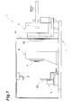
Fig. 1 is a side view showing a schematic configuration of a neutron beam irradiation apparatus which is provided with a collimator according to an embodiment of the present invention. -
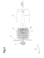
Fig. 2 is a conceptual diagram showing a state where neutrons passing through the collimator inFig. 1 are irradiated to an irradiation target of an irradiated body. -
Fig. 3 (a) is a front view of the collimator, andFig. 3 (b) is a side view of the collimator. -
Fig. 4(a) is a front view showing an irradiation field formed by leaf plates, and an irradiation target, andFig. 4(b) is a cross-sectional view taken along line IVB - IVB ofFig. 4(a) . -
Fig. 5(a) is a cross-sectional view of a collimator according to another embodiment of the present invention, andFig. 5 (b) is a cross-sectional view of a collimator of the related art. - Hereinafter, embodiments of the present invention will be described with reference to the drawings. In the following description, a neutron beam irradiation apparatus provided with a collimator for neutron capture therapy according to an embodiment will be described.
- As shown in
Figs. 1 and2 , a neutronbeam irradiation apparatus 1 is a neutron capture therapy apparatus for irradiating an affected area (an irradiation target) T of a patient (an irradiated body) P with a neutron beam. The neutronbeam irradiation apparatus 1 is an apparatus for boron neutron capture therapy (BNCT; Boron Neutron Capture Therapy) which selectively destroys cells of the affected area T by a nuclear reaction of a neutron with boron (10B) incorporated as a compound into the affected area T in advance. The neutronbeam irradiation apparatus 1 is provided with amovable stand 2 on which the patient P is placed, adeceleration device 3 which decelerates neutrons, a target (a neutron beam generation section) 7 which generates neutrons, and a collimator stand (a collimator supporting section) 4 provided between themovable stand 2 and thedeceleration device 3. Further, the neutronbeam irradiation apparatus 1 is provided with a CR system 8 for imaging an X-ray image of the affected area T of the patient P. - The
movable stand 2 has aplacement stand 2a on which the patient P sits down. Theplacement stand 2a is configured such that the patient P can also lie down thereon by changing the shape thereof. Themovable stand 2 is made so as to be movable in an up-and-down direction (a vertical direction), a left-right direction (a horizontal direction, a direction approaching or being separated from the deceleration device 3), and a front-back direction (a horizontal direction, a direction perpendicular to the left-right direction). - The target 7 generates neutrons by irradiating an ion beam (for example, a proton beam) emitted from an accelerator (not shown) thereto. The
deceleration device 3 decelerates neutrons generated by the target 7. The neutrons decelerated by thedeceleration device 3 are emitted to the patient P side. A shielding wall W is configured by concrete or the like and prevents unnecessary radiation irradiation to the patient P or the outside of a treatment room. Atip portion 3a of thedeceleration device 3 passes through the shielding wall W. The collimator stand 4 moves, thereby approaching thedeceleration device 3, whereby thetip portion 3a can enter into the back side of the collimator stand 4. Regarding thecollimator stand 4, a "back side" is the upstream side of the ion beam and a "front side" is the patient P side. - In the collimator stand 4, a collimator (a collimator for neutron capture therapy) 6 is provided to protrude to the
movable stand 2 side. The collimator 6 is for shaping the neutrons emitted from thedeceleration device 3 into a predetermined shape (an irradiation range) and extracting the neutrons in an irradiation direction Y. Thecollimator stand 4 is made so as to be movable in the front-back direction. In the back surface of thecollimator stand 4, a concave portion receiving thetip portion 3a of thedeceleration device 3 is formed. Thecollimator stand 4 is used in a state where thetip portion 3a has entered into the concave portion on the back side. At the time of treatment, the placement stand 2a with the patient P placed thereon is brought close to the front side of thecollimator stand 4, whereby the collimator 6 is disposed so as to face the affected area T of the patient P. - As shown in
Figs. 2 and3 , the collimator 6 sets an irradiation field F which is an irradiation range of a neutron beam, in accordance with the domain of the affected area T of the patient P. The collimator 6 has an outer shape of a rectangular parallelepiped shape. The collimator 6 has a plurality ofleaf plates leaf plates leaf plates leaf plates leaf plates collimator holder 11, thereby configuring aleaf plate group 13. - A guide member (a support portion in a second direction) 12 having a plurality of
projections 16 for guiding theleaf plates collimator holder 11 and theleaf plate group 13. An end portion in the irradiation direction Y of each of theleaf plates guide member 12, has a concavo-convex shape capable of being fitted to theprojection 16 of theguide member 12. - In the collimator 6 of this embodiment, each of the
leaf plates 13A (in the example ofFig. 3 , four for each of the top and the bottom) disposed at an upper end portion and a lower end portion of theleaf plate group 13 is a plate material divided into two in the left-right direction X. Each of theleaf plates 13B disposed at an intermediate portion excluding the upper end portion and the lower end portion of theleaf plate group 13 is configured by twoseparate leaf plates separate leaf plate 14 and theseparate leaf plate 15 are provided side by side in the left-right direction X. Theseparate leaf plate 14 is disposed outside (that is, near the collimator holder 11), and theseparate leaf plate 15 is disposed inside (that is, near the irradiation field F) adjacent to theseparate leaf plate 14. Theseparate leaf plate 14 and theseparate leaf plate 15 are made so as to be slidable in the left-right direction X in an integrated manner. In this manner, theleaf plate 13B is slidable in the left-right direction X, and therefore, it is possible to arbitrarily set the shape and the size of the irradiation field F. In addition, theleaf plate 13A is not limited to a case of being divided into two in the left-right direction X and may be divided into, for example, four. - In addition, in the collimator 6, the
separate leaf plate 15 of theleaf plate 13B is also made so as to be slidable in the irradiation direction Y. As shown inFigs. 3 and4 , a protrudingportion 17 protruding in the left-right direction X and also extending in the irradiation direction Y is formed on the end face of theseparate leaf plate 15, which comes into contact with theseparate leaf plate 14. On the other hand, a groove portion (a support portion in the irradiation direction) 18 extending in the irradiation direction Y direction is formed in the end face of theseparate leaf plate 14, which comes into contact with theseparate leaf plate 15. Theseparate leaf plate 14 and theseparate leaf plate 15 are respectively made so as to be slidable in the irradiation direction Y in a state where the protrudingportion 17 is fitted into thegroove portion 18. In addition, thegroove portion 18 may also function as a locking portion which locks an end portion of theseparate leaf plate 15 supported so as to be slidable in the irradiation direction Y. - The collimator 6 having the above-described configuration is a 2-axis slide type multileaf collimator slidable in the left-right direction X and the irradiation direction Y. In the collimator 6, it is possible to freely change the outer shape of the
leaf plate group 13 in the left-right direction X and the irradiation direction Y. - When treating the affected area T of the patient P, the shape of an irradiation site is examined in advance and the position of each of the
leaf plates leaf plates - According to the collimator 6 of this embodiment, the plurality of
leaf plates 13B are slidable along the left-right direction X orthogonal to the irradiation direction Y, and therefore, it is possible to accurately set the irradiation field F with respect to the affected area T. In addition, theseparate leaf plate 15 of theleaf plate 13B is also slidable in the irradiation direction Y, and therefore, it is possible to bring a marginal edge of theseparate leaf plate 15 close to a body surface Pa of the patient P so as to conform to the shape of the irradiation site. A gap between the collimator 6 and the patient P is narrowed thereby, and thus dispersion of neutrons is suppressed. As a result, a neutron dose which is irradiated to the affected area T per hour is secured, and thus it is possible to shorten irradiation time. This also contributes to a reduction in the burden on the patient P at the time of treatment. - A neutron has a property of being relatively easily dispersed. In a collimator of the related art, since it is not possible to change an outer shape, it is difficult to make an end face of the collimator be fitted according to the shape of an irradiation site. According to the collimator 6 of this embodiment, a gap between the body surface Pa of the patient P and the
leaf plates - Further, the plurality of
separate leaf plates 15 of theleaf plates 13B are respectively independently slidable in the irradiation direction Y, and therefore, for example, even in a case where the irradiation site of the patient P is rounded over the left-right direction X, by sliding the respectiveseparate leaves leaf plates Fig. 4 ). Dispersion of neutrons is even further suppressed thereby. -
Fig. 5(a) is a cross-sectional view of a collimator according to another embodiment, andFig. 5(b) is a cross-sectional view of a collimator of the related art. Aleaf plate 23 of acollimator 20 shown inFig. 5 (a) is different from theleaf plate 13B of the collimator 6 shown inFig. 3 in that theleaf plate 23 is provided withseparate leaf plates separate leaf plates 24 to 26 are cut out, wherebytapered portions 24a to 26a are formed at the respectiveseparate leaf plates 24 to 26. Among theseparate leaf plates separate leaf plates separate leaf plate 24 are made so as to be slidable in the irradiation direction Y. - As shown in
Fig. 5 (a) , due to the points that the respectiveseparate leaf plates 24 to 26 have the taperedportions 24a to 26a and that theseparate leaf plates Fig. 5(a) , a case where a neutron beam is irradiated to the affected area T (for example, a tumor) which is present in a neck portion G of the patient P is shown. The neck portion G of the patient P is present between a jaw portion H and a shoulder portion E. Even in such a case, theseparate leaf plates collimator 20. Due to the effects, high-dose-rate irradiation becomes possible, and thus the shortening of irradiation time is attained. Furthermore, due to having a tapered structure obliquely cut on the neutron incidence side, it is possible to widen a direction of incident neutrons, and thus it is possible to use a lot of neutrons capable of contributing to the irradiation to the affected area T. - On the other hand, in a
collimator 50 of the related art shown inFig. 5(b) , neutron are dispersed from a gap between a leaf plate and the body surface Pa of the patient P, and thus a neutron beam source is wasted. - The basic role of a collimator is for cutting radiation outside an irradiated area, thereby making exposure of normal tissue be less than or equal to a negligible amount. Radiation therapy (for example, X-ray therapy or proton therapy) of the related art basically collimates radiation which is emitted from one point and goes straight ahead, in accordance with an irradiated area, and a flat plate-shaped collimator is set at a place distant by several cm from an irradiation body surface. In a case of neutrons, most thereof become scattered radiation even in an atomic reactor or even in an accelerator and neutrons arriving in a direction of a collimator from a very large area compared to the collimator are used. In a case of neutrons, due to being a volume source, rather than a point source, an angle (a solid angle) over which a collimator opening can be viewed from a tumor is large, and thus the availability of neutrons from a wider radiation source area becomes a condition for increasing a dose rate. At the same time, if dispersion of neutrons from the gap between the collimator and the irradiation body surface can be prevented, this is reflected in an increase in the dose rate of the component, and it is possible to avoid portions other than an irradiation area being exposed to dispersed neutrons. A rise in the utilization efficiency of the neutrons is one effect of the
neutron collimators 6 and 20 according to the embodiments of the present invention. Other effects are to reduce the exposure of normal tissue by cutting radiation outside an irradiated area and to attain the optimization of irradiation taking into account the correlation between reduction measures and a request of a conflicting dose rate increase. - The embodiments of the present invention have been described above. However, the present invention is not limited to the above-described embodiments.
- For example, the separate leaf plates are not limited to two or three and there may be four or more. In a case where there are three or more separate leaf plates, it is possible to make the separate leaf plates other than the separate leaf plates on the outermost side (the
collimator holder 11 side in the left-right direction X) be slidable in the irradiation direction Y. In addition, only the separate leaf plates on the innermost side (the irradiation field F side) may be made to be slidable in the irradiation direction Y. Further, a drive mechanism connected to each of theseparate leaf plates leaf plate 13A and theleaf plate 13B may be provided. As the drive mechanism, for example, a roller and a motor, or a piston or the like can be used. Due to the drive mechanism, it is possible to automate the movement and the positioning of theleaf plates - The support portion in the irradiation direction may be 14 provided at the
separate leaf plate 14 and a support mechanism may be provided as a separate member at an end portion of theseparate leaf plate 14. Thecollimator stand 4 may not be provided independently, and a portion supporting the collimator may be provided at, for example, the shielding wall W or thedeceleration device 3. - Furthermore, the present invention is not limited to BNCT using a boron compound and may be applied to NCT using other elements. For example, the present invention can also be applied as a collimator which is used in a therapeutic method using a nuclear reaction of a neutron with gadolinium (157Gd or the like). In a case where the speed of a neutron beam obtained from the neutron beam generation section is a speed suitable for treatment, the deceleration device is unnecessary.
- The present invention is applicable to a collimator for neutron capture therapy and a neutron capture therapy apparatus, in which a neutron dose which is irradiated to an affected area per hour is secured, and thus it is possible to shorten irradiation time.
-
- 1: neutron beam irradiation apparatus
- 6, 20: collimator
- 13A, 13B: leaf plate
- 14, 15: separate leaf plate
- 18: groove portion (support portion in an irradiation direction)
- F: irradiation field (irradiation range)
- P: patient (irradiated body)
- T: affected area (irradiation target)
- X: left-right direction (second direction)
- Y: irradiation direction
- Z: up-and-down direction (first direction)
Claims (5)
- A collimator for neutron capture therapy which sets an irradiation range of a neutron beam in accordance with an irradiation target in an irradiated body, comprising:a plurality of leaf plates stacked in a first direction orthogonal to an irradiation direction of the neutron beam,wherein at least some leaf plates among the plurality of leaf plates are configured to be slidable along a second direction orthogonal to the irradiation direction and orthogonal to the first direction and also slidable in the irradiation direction.
- The collimator for neutron capture therapy according to Claim 1, wherein at least some leaf plates have a plurality of separate leaf plates divided in the second direction, and
the plurality of separate leaf plates are configured to be respectively independently slidable in the irradiation direction. - A collimator for neutron capture therapy which sets an irradiation range of a neutron beam in accordance with an irradiation target in an irradiated body, comprising:a plurality of leaf plates which are stacked in a first direction orthogonal to an irradiation direction of the neutron beam and in which at least some of the plurality of leaf plates are divided into at least four separate leaf plates in a second direction orthogonal to the irradiation direction and the first direction;a support portion in the second direction which is configured to support the leaf plate so as to be slidable along the second direction; anda support portion in the irradiation direction which is configured to support an inner separate leaf plate of the separate leaf plates divided in the second direction so as to be slidable along the irradiation direction.
- The collimator for neutron capture therapy according to Claim 3, wherein the support portion in the irradiation direction is a locking portion which is provided at the separate leaf plate adjacent to the separate leaf plate supported so as to be slidable along the irradiation direction and is configured to lock an end portion of the separate leaf plate supported so as to be slidable along the irradiation direction.
- A neutron capture therapy apparatus comprising:a neutron beam generation section which is configured to generate a neutron beam;the collimator for neutron capture therapy according to any one of Claims 1 to 4; anda collimator supporting section which is configured to support the collimator for neutron capture therapy.
Applications Claiming Priority (2)
| Application Number | Priority Date | Filing Date | Title |
|---|---|---|---|
| JP2012080230A JP5630666B2 (en) | 2012-03-30 | 2012-03-30 | Neutron capture therapy collimator and neutron capture therapy device |
| PCT/JP2013/057485 WO2013146373A1 (en) | 2012-03-30 | 2013-03-15 | Collimator for neutron capture therapy and neutron capture therapy apparatus |
Publications (3)
| Publication Number | Publication Date |
|---|---|
| EP2835149A1 true EP2835149A1 (en) | 2015-02-11 |
| EP2835149A4 EP2835149A4 (en) | 2015-10-21 |
| EP2835149B1 EP2835149B1 (en) | 2017-11-01 |
Family
ID=49259634
Family Applications (1)
| Application Number | Title | Priority Date | Filing Date |
|---|---|---|---|
| EP13769074.9A Not-in-force EP2835149B1 (en) | 2012-03-30 | 2013-03-15 | Collimator for neutron capture therapy and neutron capture therapy apparatus |
Country Status (6)
| Country | Link |
|---|---|
| EP (1) | EP2835149B1 (en) |
| JP (1) | JP5630666B2 (en) |
| KR (1) | KR101441522B1 (en) |
| CN (1) | CN104053476B (en) |
| TW (1) | TWI486189B (en) |
| WO (1) | WO2013146373A1 (en) |
Cited By (1)
| Publication number | Priority date | Publication date | Assignee | Title |
|---|---|---|---|---|
| WO2021170722A1 (en) * | 2020-02-26 | 2021-09-02 | Varian Medical Systems International Ag | Beam-blocking leaf and multileaf collimator containing same |
Families Citing this family (19)
| Publication number | Priority date | Publication date | Assignee | Title |
|---|---|---|---|---|
| TWI532056B (en) | 2013-10-15 | 2016-05-01 | 財團法人工業技術研究院 | Filter and neutron beam source including the same |
| US9962560B2 (en) * | 2013-12-20 | 2018-05-08 | Mevion Medical Systems, Inc. | Collimator and energy degrader |
| CN104511096B (en) * | 2014-12-08 | 2018-01-05 | 南京中硼联康医疗科技有限公司 | Beam Shapers for Neutron Capture Therapy |
| JP6430264B2 (en) * | 2015-01-19 | 2018-11-28 | 住友重機械工業株式会社 | Negative ion source device |
| JP6565113B2 (en) * | 2015-03-05 | 2019-08-28 | 住友重機械工業株式会社 | Neutron capture therapy device |
| JP6566358B2 (en) * | 2015-10-27 | 2019-08-28 | 住友重機械工業株式会社 | Neutron capture therapy simulation system and neutron capture therapy simulation method |
| RU2734955C1 (en) * | 2017-06-05 | 2020-10-26 | Нойборон Медтех Лтд. | Beam forming unit for neutron capturing therapy |
| US10446281B2 (en) * | 2017-08-15 | 2019-10-15 | Westinghouse Electric Company Llc | Detection apparatus and method of detecting the neutron absorption capability of a control element of a nuclear installation |
| CN109925611B (en) * | 2017-12-18 | 2024-04-16 | 南京中硼联康医疗科技有限公司 | Neutron capture therapy device |
| CN109925613B (en) * | 2017-12-18 | 2024-04-12 | 南京中硼联康医疗科技有限公司 | Neutron capture therapeutic device |
| JP7207856B2 (en) * | 2018-03-12 | 2023-01-18 | 東芝Itコントロールシステム株式会社 | CT imaging device |
| JP7082914B2 (en) * | 2018-07-19 | 2022-06-09 | 住友重機械工業株式会社 | How to install a collimator for neutron capture therapy and a neutron beam collimator |
| KR102118077B1 (en) * | 2018-11-06 | 2020-06-02 | 한국원자력의학원 | Collimator for Neutron Capture Therapy System |
| CN109499011B (en) * | 2018-12-21 | 2020-11-10 | 苏州雷泰医疗科技有限公司 | Dynamic intensity modulated subfield segmentation method for orthogonal double-layer grating device |
| GB2592987A (en) * | 2020-03-13 | 2021-09-15 | Elekta ltd | Leaf for a multi-leaf collimator |
| CN111388881B (en) * | 2020-03-23 | 2022-01-28 | 上海联影医疗科技股份有限公司 | Control method and system of beam limiting device |
| CN112999533A (en) * | 2021-04-29 | 2021-06-22 | 北京凯佰特科技股份有限公司 | Position adjusting device for neutron irradiator in hospital |
| CN115120895A (en) * | 2022-08-31 | 2022-09-30 | 兰州大学 | A neutron capture irradiation equipment |
| CN115300812A (en) * | 2022-08-31 | 2022-11-08 | 兰州大学 | Neutron beam grating irradiation system |
Family Cites Families (12)
| Publication number | Priority date | Publication date | Assignee | Title |
|---|---|---|---|---|
| US4463266A (en) * | 1981-02-20 | 1984-07-31 | Instrument Ab Scanditronix | Neutron collimator |
| JPS59230199A (en) * | 1983-06-14 | 1984-12-24 | 住友重機械工業株式会社 | Collimating plate for neutron ray |
| US5818902A (en) * | 1996-03-01 | 1998-10-06 | Elekta Ab | Intensity modulated arc therapy with dynamic multi-leaf collimation |
| JP2002186676A (en) * | 2000-12-22 | 2002-07-02 | Hitachi Medical Corp | Diaphragm device and radiotherapy device using the diaphragm device |
| JP3779878B2 (en) | 2001-01-30 | 2006-05-31 | 株式会社日立製作所 | Multi-leaf collimator |
| JP2005185321A (en) * | 2003-12-24 | 2005-07-14 | Toshiba Corp | Collimator, radiotherapy apparatus and radiotherapy system |
| WO2009000155A1 (en) * | 2007-06-21 | 2008-12-31 | Tsinghua University | A photoneutron conversion target |
| JP4680074B2 (en) * | 2006-01-30 | 2011-05-11 | 三菱電機株式会社 | Particle beam therapy system |
| JP4602366B2 (en) | 2007-02-23 | 2010-12-22 | 株式会社日立製作所 | Multi-leaf collimator |
| JP5154255B2 (en) | 2008-02-18 | 2013-02-27 | 住友重機械工業株式会社 | Neutron irradiation equipment |
| US9268027B2 (en) * | 2008-05-12 | 2016-02-23 | Nuctech Company Ltd. | Method and system for detecting special nuclear materials |
| CN101757737B (en) * | 2008-12-24 | 2012-11-14 | 住友重机械工业株式会社 | Multi-leaf collimator and radiotherapy device |
-
2012
- 2012-03-30 JP JP2012080230A patent/JP5630666B2/en not_active Expired - Fee Related
-
2013
- 2013-03-15 WO PCT/JP2013/057485 patent/WO2013146373A1/en not_active Ceased
- 2013-03-15 KR KR1020147019467A patent/KR101441522B1/en not_active Expired - Fee Related
- 2013-03-15 CN CN201380005563.3A patent/CN104053476B/en not_active Expired - Fee Related
- 2013-03-15 EP EP13769074.9A patent/EP2835149B1/en not_active Not-in-force
- 2013-03-21 TW TW102106202A patent/TWI486189B/en not_active IP Right Cessation
Cited By (1)
| Publication number | Priority date | Publication date | Assignee | Title |
|---|---|---|---|---|
| WO2021170722A1 (en) * | 2020-02-26 | 2021-09-02 | Varian Medical Systems International Ag | Beam-blocking leaf and multileaf collimator containing same |
Also Published As
| Publication number | Publication date |
|---|---|
| KR101441522B1 (en) | 2014-09-17 |
| TW201350166A (en) | 2013-12-16 |
| TWI486189B (en) | 2015-06-01 |
| JP5630666B2 (en) | 2014-11-26 |
| CN104053476B (en) | 2015-11-25 |
| CN104053476A (en) | 2014-09-17 |
| EP2835149A4 (en) | 2015-10-21 |
| KR20140093760A (en) | 2014-07-28 |
| EP2835149B1 (en) | 2017-11-01 |
| WO2013146373A1 (en) | 2013-10-03 |
| JP2013208257A (en) | 2013-10-10 |
Similar Documents
| Publication | Publication Date | Title |
|---|---|---|
| EP2835149B1 (en) | Collimator for neutron capture therapy and neutron capture therapy apparatus | |
| JP6129899B2 (en) | Beam shaping assembly for neutron capture therapy | |
| CN114452550B (en) | Beam flow distribution system for ion Flash treatment | |
| RU2717363C1 (en) | Beam forming unit for neutron capture therapy | |
| RU2707651C1 (en) | Apparatus for neutron therapy | |
| JP2013208257A5 (en) | ||
| JP2025027080A (en) | Radiation irradiation system and control method thereof | |
| JP2020519420A (en) | Neutron capture therapy system | |
| JP2018535717A (en) | Beam shaper used in neutron capture therapy | |
| JP2019519332A (en) | Neutron treatment device | |
| CN108355257B (en) | Beam shapers for neutron capture therapy | |
| JP5850362B2 (en) | Neutron beam irradiation apparatus and method of operating the apparatus | |
| WO2025044837A1 (en) | Flash therapeutic system, radiation shielding protection method, and related device | |
| CN107292075B (en) | Methods for improving the computational efficiency of radiation therapy systems | |
| CN107569779B (en) | Neutron therapeutic device | |
| KR102118077B1 (en) | Collimator for Neutron Capture Therapy System | |
| KR20210016118A (en) | Collimator for Considering the patient positioning | |
| US20240325789A1 (en) | Radiation exposure system, and placement platform controlling method thereof | |
| RU2844408C2 (en) | Radiation effect system and its placement platform control method | |
| CN107569778B (en) | Neutron therapeutic device | |
| US12527972B2 (en) | Beam shaping device for boron neutron capture therapy apparatus, and boron neutron capture therapy apparatus comprising same | |
| Balasubramanian et al. | Measurements of peripheral dose for multileaf collimator based linear accelerator | |
| TWM549081U (en) | Neutron therapy device | |
| JP2022082310A (en) | Collimator, method for using collimator, and particle beam treatment system | |
| Varatharaj et al. | Peripheral dose from a dual energy linear accelerator equipped with tertiary multileaf collimators and enhanced dynamic wedge |
Legal Events
| Date | Code | Title | Description |
|---|---|---|---|
| PUAI | Public reference made under article 153(3) epc to a published international application that has entered the european phase |
Free format text: ORIGINAL CODE: 0009012 |
|
| 17P | Request for examination filed |
Effective date: 20141014 |
|
| AK | Designated contracting states |
Kind code of ref document: A1 Designated state(s): AL AT BE BG CH CY CZ DE DK EE ES FI FR GB GR HR HU IE IS IT LI LT LU LV MC MK MT NL NO PL PT RO RS SE SI SK SM TR |
|
| AX | Request for extension of the european patent |
Extension state: BA ME |
|
| DAX | Request for extension of the european patent (deleted) | ||
| RA4 | Supplementary search report drawn up and despatched (corrected) |
Effective date: 20150917 |
|
| RIC1 | Information provided on ipc code assigned before grant |
Ipc: A61N 5/10 20060101AFI20150911BHEP Ipc: G21K 1/04 20060101ALI20150911BHEP |
|
| RIC1 | Information provided on ipc code assigned before grant |
Ipc: A61N 5/10 20060101AFI20170313BHEP Ipc: G21K 1/04 20060101ALI20170313BHEP |
|
| GRAP | Despatch of communication of intention to grant a patent |
Free format text: ORIGINAL CODE: EPIDOSNIGR1 |
|
| INTG | Intention to grant announced |
Effective date: 20170517 |
|
| GRAS | Grant fee paid |
Free format text: ORIGINAL CODE: EPIDOSNIGR3 |
|
| GRAA | (expected) grant |
Free format text: ORIGINAL CODE: 0009210 |
|
| AK | Designated contracting states |
Kind code of ref document: B1 Designated state(s): AL AT BE BG CH CY CZ DE DK EE ES FI FR GB GR HR HU IE IS IT LI LT LU LV MC MK MT NL NO PL PT RO RS SE SI SK SM TR |
|
| REG | Reference to a national code |
Ref country code: GB Ref legal event code: FG4D |
|
| REG | Reference to a national code |
Ref country code: CH Ref legal event code: EP Ref country code: AT Ref legal event code: REF Ref document number: 941455 Country of ref document: AT Kind code of ref document: T Effective date: 20171115 |
|
| REG | Reference to a national code |
Ref country code: IE Ref legal event code: FG4D |
|
| REG | Reference to a national code |
Ref country code: DE Ref legal event code: R096 Ref document number: 602013028790 Country of ref document: DE |
|
| REG | Reference to a national code |
Ref country code: NL Ref legal event code: MP Effective date: 20171101 |
|
| REG | Reference to a national code |
Ref country code: LT Ref legal event code: MG4D |
|
| REG | Reference to a national code |
Ref country code: AT Ref legal event code: MK05 Ref document number: 941455 Country of ref document: AT Kind code of ref document: T Effective date: 20171101 |
|
| PG25 | Lapsed in a contracting state [announced via postgrant information from national office to epo] |
Ref country code: LT Free format text: LAPSE BECAUSE OF FAILURE TO SUBMIT A TRANSLATION OF THE DESCRIPTION OR TO PAY THE FEE WITHIN THE PRESCRIBED TIME-LIMIT Effective date: 20171101 Ref country code: NL Free format text: LAPSE BECAUSE OF FAILURE TO SUBMIT A TRANSLATION OF THE DESCRIPTION OR TO PAY THE FEE WITHIN THE PRESCRIBED TIME-LIMIT Effective date: 20171101 Ref country code: ES Free format text: LAPSE BECAUSE OF FAILURE TO SUBMIT A TRANSLATION OF THE DESCRIPTION OR TO PAY THE FEE WITHIN THE PRESCRIBED TIME-LIMIT Effective date: 20171101 Ref country code: NO Free format text: LAPSE BECAUSE OF FAILURE TO SUBMIT A TRANSLATION OF THE DESCRIPTION OR TO PAY THE FEE WITHIN THE PRESCRIBED TIME-LIMIT Effective date: 20180201 Ref country code: SE Free format text: LAPSE BECAUSE OF FAILURE TO SUBMIT A TRANSLATION OF THE DESCRIPTION OR TO PAY THE FEE WITHIN THE PRESCRIBED TIME-LIMIT Effective date: 20171101 |
|
| PG25 | Lapsed in a contracting state [announced via postgrant information from national office to epo] |
Ref country code: LV Free format text: LAPSE BECAUSE OF FAILURE TO SUBMIT A TRANSLATION OF THE DESCRIPTION OR TO PAY THE FEE WITHIN THE PRESCRIBED TIME-LIMIT Effective date: 20171101 Ref country code: GR Free format text: LAPSE BECAUSE OF FAILURE TO SUBMIT A TRANSLATION OF THE DESCRIPTION OR TO PAY THE FEE WITHIN THE PRESCRIBED TIME-LIMIT Effective date: 20180202 Ref country code: AT Free format text: LAPSE BECAUSE OF FAILURE TO SUBMIT A TRANSLATION OF THE DESCRIPTION OR TO PAY THE FEE WITHIN THE PRESCRIBED TIME-LIMIT Effective date: 20171101 Ref country code: HR Free format text: LAPSE BECAUSE OF FAILURE TO SUBMIT A TRANSLATION OF THE DESCRIPTION OR TO PAY THE FEE WITHIN THE PRESCRIBED TIME-LIMIT Effective date: 20171101 Ref country code: RS Free format text: LAPSE BECAUSE OF FAILURE TO SUBMIT A TRANSLATION OF THE DESCRIPTION OR TO PAY THE FEE WITHIN THE PRESCRIBED TIME-LIMIT Effective date: 20171101 Ref country code: IS Free format text: LAPSE BECAUSE OF FAILURE TO SUBMIT A TRANSLATION OF THE DESCRIPTION OR TO PAY THE FEE WITHIN THE PRESCRIBED TIME-LIMIT Effective date: 20180301 Ref country code: BG Free format text: LAPSE BECAUSE OF FAILURE TO SUBMIT A TRANSLATION OF THE DESCRIPTION OR TO PAY THE FEE WITHIN THE PRESCRIBED TIME-LIMIT Effective date: 20180201 |
|
| PG25 | Lapsed in a contracting state [announced via postgrant information from national office to epo] |
Ref country code: DK Free format text: LAPSE BECAUSE OF FAILURE TO SUBMIT A TRANSLATION OF THE DESCRIPTION OR TO PAY THE FEE WITHIN THE PRESCRIBED TIME-LIMIT Effective date: 20171101 Ref country code: SK Free format text: LAPSE BECAUSE OF FAILURE TO SUBMIT A TRANSLATION OF THE DESCRIPTION OR TO PAY THE FEE WITHIN THE PRESCRIBED TIME-LIMIT Effective date: 20171101 Ref country code: CY Free format text: LAPSE BECAUSE OF FAILURE TO SUBMIT A TRANSLATION OF THE DESCRIPTION OR TO PAY THE FEE WITHIN THE PRESCRIBED TIME-LIMIT Effective date: 20171101 Ref country code: EE Free format text: LAPSE BECAUSE OF FAILURE TO SUBMIT A TRANSLATION OF THE DESCRIPTION OR TO PAY THE FEE WITHIN THE PRESCRIBED TIME-LIMIT Effective date: 20171101 Ref country code: CZ Free format text: LAPSE BECAUSE OF FAILURE TO SUBMIT A TRANSLATION OF THE DESCRIPTION OR TO PAY THE FEE WITHIN THE PRESCRIBED TIME-LIMIT Effective date: 20171101 |
|
| REG | Reference to a national code |
Ref country code: DE Ref legal event code: R097 Ref document number: 602013028790 Country of ref document: DE |
|
| PG25 | Lapsed in a contracting state [announced via postgrant information from national office to epo] |
Ref country code: IT Free format text: LAPSE BECAUSE OF FAILURE TO SUBMIT A TRANSLATION OF THE DESCRIPTION OR TO PAY THE FEE WITHIN THE PRESCRIBED TIME-LIMIT Effective date: 20171101 Ref country code: SM Free format text: LAPSE BECAUSE OF FAILURE TO SUBMIT A TRANSLATION OF THE DESCRIPTION OR TO PAY THE FEE WITHIN THE PRESCRIBED TIME-LIMIT Effective date: 20171101 Ref country code: PL Free format text: LAPSE BECAUSE OF FAILURE TO SUBMIT A TRANSLATION OF THE DESCRIPTION OR TO PAY THE FEE WITHIN THE PRESCRIBED TIME-LIMIT Effective date: 20171101 Ref country code: RO Free format text: LAPSE BECAUSE OF FAILURE TO SUBMIT A TRANSLATION OF THE DESCRIPTION OR TO PAY THE FEE WITHIN THE PRESCRIBED TIME-LIMIT Effective date: 20171101 |
|
| PLBE | No opposition filed within time limit |
Free format text: ORIGINAL CODE: 0009261 |
|
| STAA | Information on the status of an ep patent application or granted ep patent |
Free format text: STATUS: NO OPPOSITION FILED WITHIN TIME LIMIT |
|
| 26N | No opposition filed |
Effective date: 20180802 |
|
| REG | Reference to a national code |
Ref country code: CH Ref legal event code: PL |
|
| GBPC | Gb: european patent ceased through non-payment of renewal fee |
Effective date: 20180315 |
|
| PG25 | Lapsed in a contracting state [announced via postgrant information from national office to epo] |
Ref country code: MC Free format text: LAPSE BECAUSE OF FAILURE TO SUBMIT A TRANSLATION OF THE DESCRIPTION OR TO PAY THE FEE WITHIN THE PRESCRIBED TIME-LIMIT Effective date: 20171101 Ref country code: SI Free format text: LAPSE BECAUSE OF FAILURE TO SUBMIT A TRANSLATION OF THE DESCRIPTION OR TO PAY THE FEE WITHIN THE PRESCRIBED TIME-LIMIT Effective date: 20171101 |
|
| REG | Reference to a national code |
Ref country code: BE Ref legal event code: MM Effective date: 20180331 |
|
| REG | Reference to a national code |
Ref country code: IE Ref legal event code: MM4A |
|
| PG25 | Lapsed in a contracting state [announced via postgrant information from national office to epo] |
Ref country code: LU Free format text: LAPSE BECAUSE OF NON-PAYMENT OF DUE FEES Effective date: 20180315 |
|
| PG25 | Lapsed in a contracting state [announced via postgrant information from national office to epo] |
Ref country code: IE Free format text: LAPSE BECAUSE OF NON-PAYMENT OF DUE FEES Effective date: 20180315 |
|
| PG25 | Lapsed in a contracting state [announced via postgrant information from national office to epo] |
Ref country code: GB Free format text: LAPSE BECAUSE OF NON-PAYMENT OF DUE FEES Effective date: 20180315 Ref country code: BE Free format text: LAPSE BECAUSE OF NON-PAYMENT OF DUE FEES Effective date: 20180331 Ref country code: CH Free format text: LAPSE BECAUSE OF NON-PAYMENT OF DUE FEES Effective date: 20180331 Ref country code: LI Free format text: LAPSE BECAUSE OF NON-PAYMENT OF DUE FEES Effective date: 20180331 |
|
| PG25 | Lapsed in a contracting state [announced via postgrant information from national office to epo] |
Ref country code: FR Free format text: LAPSE BECAUSE OF NON-PAYMENT OF DUE FEES Effective date: 20180331 |
|
| PG25 | Lapsed in a contracting state [announced via postgrant information from national office to epo] |
Ref country code: MT Free format text: LAPSE BECAUSE OF NON-PAYMENT OF DUE FEES Effective date: 20180315 |
|
| PG25 | Lapsed in a contracting state [announced via postgrant information from national office to epo] |
Ref country code: TR Free format text: LAPSE BECAUSE OF FAILURE TO SUBMIT A TRANSLATION OF THE DESCRIPTION OR TO PAY THE FEE WITHIN THE PRESCRIBED TIME-LIMIT Effective date: 20171101 |
|
| PGFP | Annual fee paid to national office [announced via postgrant information from national office to epo] |
Ref country code: DE Payment date: 20200303 Year of fee payment: 8 Ref country code: FI Payment date: 20200309 Year of fee payment: 8 |
|
| PG25 | Lapsed in a contracting state [announced via postgrant information from national office to epo] |
Ref country code: PT Free format text: LAPSE BECAUSE OF FAILURE TO SUBMIT A TRANSLATION OF THE DESCRIPTION OR TO PAY THE FEE WITHIN THE PRESCRIBED TIME-LIMIT Effective date: 20171101 |
|
| PG25 | Lapsed in a contracting state [announced via postgrant information from national office to epo] |
Ref country code: MK Free format text: LAPSE BECAUSE OF NON-PAYMENT OF DUE FEES Effective date: 20171101 Ref country code: HU Free format text: LAPSE BECAUSE OF FAILURE TO SUBMIT A TRANSLATION OF THE DESCRIPTION OR TO PAY THE FEE WITHIN THE PRESCRIBED TIME-LIMIT; INVALID AB INITIO Effective date: 20130315 |
|
| PG25 | Lapsed in a contracting state [announced via postgrant information from national office to epo] |
Ref country code: AL Free format text: LAPSE BECAUSE OF FAILURE TO SUBMIT A TRANSLATION OF THE DESCRIPTION OR TO PAY THE FEE WITHIN THE PRESCRIBED TIME-LIMIT Effective date: 20171101 |
|
| REG | Reference to a national code |
Ref country code: DE Ref legal event code: R119 Ref document number: 602013028790 Country of ref document: DE |
|
| REG | Reference to a national code |
Ref country code: FI Ref legal event code: MAE |
|
| PG25 | Lapsed in a contracting state [announced via postgrant information from national office to epo] |
Ref country code: FI Free format text: LAPSE BECAUSE OF NON-PAYMENT OF DUE FEES Effective date: 20210315 |
|
| PG25 | Lapsed in a contracting state [announced via postgrant information from national office to epo] |
Ref country code: DE Free format text: LAPSE BECAUSE OF NON-PAYMENT OF DUE FEES Effective date: 20211001 |