EP2835109A1 - Nozzle tip - Google Patents
Nozzle tip Download PDFInfo
- Publication number
- EP2835109A1 EP2835109A1 EP14002617.0A EP14002617A EP2835109A1 EP 2835109 A1 EP2835109 A1 EP 2835109A1 EP 14002617 A EP14002617 A EP 14002617A EP 2835109 A1 EP2835109 A1 EP 2835109A1
- Authority
- EP
- European Patent Office
- Prior art keywords
- tip
- mixing
- cylindrical portion
- nozzle tip
- outer diameter
- Prior art date
- Legal status (The legal status is an assumption and is not a legal conclusion. Google has not performed a legal analysis and makes no representation as to the accuracy of the status listed.)
- Granted
Links
Images


Classifications
-
- B—PERFORMING OPERATIONS; TRANSPORTING
- B05—SPRAYING OR ATOMISING IN GENERAL; APPLYING FLUENT MATERIALS TO SURFACES, IN GENERAL
- B05B—SPRAYING APPARATUS; ATOMISING APPARATUS; NOZZLES
- B05B15/00—Details of spraying plant or spraying apparatus not otherwise provided for; Accessories
- B05B15/60—Arrangements for mounting, supporting or holding spraying apparatus
- B05B15/65—Mounting arrangements for fluid connection of the spraying apparatus or its outlets to flow conduits
-
- A—HUMAN NECESSITIES
- A61—MEDICAL OR VETERINARY SCIENCE; HYGIENE
- A61C—DENTISTRY; APPARATUS OR METHODS FOR ORAL OR DENTAL HYGIENE
- A61C5/00—Filling or capping teeth
- A61C5/60—Devices specially adapted for pressing or mixing capping or filling materials, e.g. amalgam presses
- A61C5/68—Mixing dental material components for immediate application to a site to be restored, e.g. a tooth cavity
-
- A—HUMAN NECESSITIES
- A61—MEDICAL OR VETERINARY SCIENCE; HYGIENE
- A61C—DENTISTRY; APPARATUS OR METHODS FOR ORAL OR DENTAL HYGIENE
- A61C9/00—Impression cups, i.e. impression trays; Impression methods
- A61C9/0026—Syringes or guns for injecting impression material; Mixing impression material for immediate use
-
- B—PERFORMING OPERATIONS; TRANSPORTING
- B05—SPRAYING OR ATOMISING IN GENERAL; APPLYING FLUENT MATERIALS TO SURFACES, IN GENERAL
- B05C—APPARATUS FOR APPLYING FLUENT MATERIALS TO SURFACES, IN GENERAL
- B05C17/00—Hand tools or apparatus using hand held tools, for applying liquids or other fluent materials to, for spreading applied liquids or other fluent materials on, or for partially removing applied liquids or other fluent materials from, surfaces
- B05C17/005—Hand tools or apparatus using hand held tools, for applying liquids or other fluent materials to, for spreading applied liquids or other fluent materials on, or for partially removing applied liquids or other fluent materials from, surfaces for discharging material from a reservoir or container located in or on the hand tool through an outlet orifice by pressure without using surface contacting members like pads or brushes
- B05C17/00503—Details of the outlet element
- B05C17/00506—Means for connecting the outlet element to, or for disconnecting it from, the hand tool or its container
-
- B—PERFORMING OPERATIONS; TRANSPORTING
- B05—SPRAYING OR ATOMISING IN GENERAL; APPLYING FLUENT MATERIALS TO SURFACES, IN GENERAL
- B05C—APPARATUS FOR APPLYING FLUENT MATERIALS TO SURFACES, IN GENERAL
- B05C17/00—Hand tools or apparatus using hand held tools, for applying liquids or other fluent materials to, for spreading applied liquids or other fluent materials on, or for partially removing applied liquids or other fluent materials from, surfaces
- B05C17/005—Hand tools or apparatus using hand held tools, for applying liquids or other fluent materials to, for spreading applied liquids or other fluent materials on, or for partially removing applied liquids or other fluent materials from, surfaces for discharging material from a reservoir or container located in or on the hand tool through an outlet orifice by pressure without using surface contacting members like pads or brushes
- B05C17/00553—Hand tools or apparatus using hand held tools, for applying liquids or other fluent materials to, for spreading applied liquids or other fluent materials on, or for partially removing applied liquids or other fluent materials from, surfaces for discharging material from a reservoir or container located in or on the hand tool through an outlet orifice by pressure without using surface contacting members like pads or brushes with means allowing the stock of material to consist of at least two different components
Definitions
- the present invention relates to a nozzle tip capable of being locked securely and unremovably after being fixed temporarily at a tip-end of a mixing tip.
- a mixing tip has been widely used at a time of mixing and kneading a pasty dental material.
- a mixing tip is detachably attached to a container, in which the dental material is stored, for example, at a mouthpiece on a tip-end of the container through a locking claw.
- a nozzle tip is attached to use depending on the application, for example, the case of directly discharging more the dental material in an oral cavity.
- the nozzle tip Since the nozzle tip is thinner and smaller than the mixing tip, large pressure is applied in the nozzle tip at a time of discharging, so that the nozzle tip is easy to come off. Therefore, for preventing problems, for example, the nozzle tip falls down in an oral cavity of a patient at a time of operation, it is important for the nozzle tip to be unremovably locked to the mixing-tip.
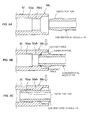
- FIG. 5 is a cross-sectional explanation view illustrating a state of inserting a conventional nozzle tip into the mixing tip.
- a contact area between the protrusion portion of the discharging port of the mixing tip and a taper portion of the nozzle tip becomes small so that insertion load can be reduced, as illustrated in Fig. 5B .
- the nozzle tip when the nozzle tip is completely inserted, the nozzle tip can be unremovably locked between a step portion continuously provided to the taper portion and an end portion on the rear side of the protrusion portion of the mixing tip, as illustrated in Fig. 5C .
- the nozzle tip is pushed back from the discharging port of the mixing tip and often falls down, since the state of the protrusion portion of the mixing tip and the taper portion of the nozzle tip is in Fig. 5B .
- the nozzle cannot be re-used hygienically, so that there has been problems that the user wastes the nozzle tip, requires wasteful time and effort for the preparation of an operation, or the like.
- the present invention is directed to provide a nozzle tip being hardly removed from the mixing tip, when a user releases or slips his hand at a time of inserting the nozzle tip, while reducing the load of inserting the nozzle tip into the discharging port of the mixing tip.
- a nozzle tip to be inserted and locked into a discharging port of a mixing tip, which is for mixing, kneading, and discharging a pasty dental material.
- the discharging port is provided with a cylindrical portion, and a protrusion portion on the tip-end side of the cylindrical portion of the mixing tip.
- the nozzle tip comprises an insertion portion which is to be inserted into the discharging port of the mixing tip.
- the insertion portion consists of a cylindrical portion for temporary fixing, a taper portion, and a cylindrical portion for engaging.
- the cylindrical portion for temporary fixing has an outer diameter which is equal to the inner diameter of the protrusion portion of the mixing tip.
- the taper portion is continuously provided on the cylindrical portion for temporary fixing.
- the outer diameter of the taper portion increases toward the tip-end side of the nozzle tip up to an outer diameter which is smaller than the inner diameter of the cylindrical portion of the mixing tip and decreases to an outer diameter which is larger than the inner diameter of the protrusion portion of the mixing tip at a step portion.
- the cylindrical portion for engaging is continuously provided on the step portion of the taper portion and has an outer diameter which is equal to the outer diameter of the taper portion at the step portion and a length which is longer than a length of the protrusion portion of the mixing tip.
- the cylindrical portion for temporary fixing of the nozzle tip is inserted in the protrusion portion of the mixing tip to have a state of temporary fixing, at first.
- a user can easily re-grip after leaving his hand. If the nozzle tip is inserted deeper, the taper portion of the nozzle tip is inserted into the protrusion portion of the mixing tip. At this time, since the contacting area between the taper portion of the nozzle tip and the protrusion portion of the mixing tip is small, the insertion load is small. Thus, the user can easily insert the nozzle tip.
- the taper portion for temporary fixing of the nozzle tip stays in the protrusion portion of the mixing tip, so that it can be hardly that the nozzle tip falls down. Furthermore, if the cylindrical portion for engaging is inserted into the protrusion portion of the mixing tip following to the taper portion, the step portion of the taper portion of the nozzle tip is locked with an end portion on the rear side of the protrusion portion of the mixing tip, so that the nozzle tip is tightly and unremovably locked to the discharging port of the mixing tip.
- the present invention is a nozzle tip to be inserted and locked into a discharging port provided on a tip-end side of the mixing tip for mixing and discharging a pasty dental material.
- the discharging port is provided with a cylindrical portion and a protrusion portion on the tip-end side of the cylindrical portion of the mixing tip.
- the nozzle tip comprises an insertion portion which is to be inserted into the discharging port of the mixing tip.
- the insertion portion consists of a cylindrical portion for temporary fixing, a taper portion, and a cylindrical portion for engaging.
- the cylindrical portion for temporary fixing has an outer diameter which is equal to the inner diameter of the protrusion portion of the mixing tip.
- the taper portion is continuously provided on the cylindrical portion for temporary fixing.
- the outer diameter of the taper portion increases toward the tip-end side of the nozzle tip up to an outer diameter which is smaller than the inner diameter of the cylindrical portion of the mixing tip and decreases to an outer diameter which is larger than the inner diameter of the protrusion portion of the mixing tip at a step portion.
- the cylindrical portion for engaging is continuously provided on the step portion of the taper portion and has an outer diameter which is equal to the outer diameter of the taper portion at the step portion and a length which is longer than a length of the protrusion portion of the mixing tip.
- a notch portion is formed on an outer periphery of the cylindrical portion for engaging side of the taper portion.
- the notch portion is cut out toward an axial direction of the taper portion at even intervals.
- the nozzle tip according to the present invention is to be inserted and locked into the discharging port of the mixing tip, which is for mixing and discharging a pasty dental material.
- the discharging port is provided with a cylindrical portion and a protrusion portion on the tip-end side of the cylindrical portion of the mixing tip.
- the nozzle tip comprises an insertion portion which is to be inserted into the discharging port of the mixing tip.
- the insertion portion consists of the cylindrical portion for temporary fixing, the taper portion, and the cylindrical portion for engaging.
- the cylindrical portion for temporary fixing has an outer diameter which is equal to the inner diameter of the protrusion portion of the mixing tip.
- the taper portion is continuously provided on the cylindrical portion for temporary fixing. The outer diameter of the taper portion increases toward the tip-end side of the nozzle tip up to an outer diameter which is smaller than the inner diameter of the cylindrical portion of the mixing tip and decreases to an outer diameter which is larger than the inner diameter of the protrusion portion of the mixing tip at a step portion.
- the cylindrical portion for engaging is continuously provided on the step portion of the taper portion and has the outer diameter which is equal to the outer diameter of the taper portion at the step portion and the length which is longer than a length of the protrusion portion of the mixing tip.
- the contacting area between the taper portion of the nozzle tip and the protrusion portion of the mixing tip is small, the insertion load is small.
- the user can easily insert the nozzle tip.
- only the taper portion is pushed back from the protrusion portion and the cylindrical portion for temporary fixing of the nozzle tip stays in the protrusion portion of the mixing tip, so that it can be hardly that the nozzle tip falls down.
- the step portion of the taper portion of the nozzle tip is locked with end portion on the rear side of the protrusion portion of the mixing tip, so that the nozzle tip is tightly and unremovably locked to the discharging port of the mixing tip.
- a notch portion is formed on an outer periphery of the cylindrical portion for engaging side of the taper portion.
- the notch portion is cut out toward an axial direction of the taper portion at even intervals. It is preferable that the insertion load, which generates between the taper portion of the nozzle tip and the discharging port of the mixing tip at a time of insertion of the nozzle tip into the protrusion portion of the mixing tip, is reduced more, so that the user can easily insert the nozzle tip.
- a mixing tip M is for mixing, kneading, and discharging a pasty dental material.
- a discharging port Ma is provided with a cylindrical portion Maa having an inner diameter d 1 and a protrusion portion Mab having an inner diameter d 2 on the tip-end side of the cylindrical portion Maa of the mixing tip M.
- the nozzle tip according to the present invention is inserted and locked into such the discharging port Ma of the mixing tip M.
- the nozzle tip comprises an insertion portion 1 which is to be inserted into the discharging port Ma of the mixing tip M.
- the insertion portion 1 consists of a cylindrical portion for temporary fixing 2, a taper portion 3, and a cylindrical portion for engaging 4, which are described later.
- the nozzle tip according to the present invention includes the insertion portion 1 and a nozzle portion, the nozzle portion is not particularly limited including a shape, or the like.
- the cylindrical portion for temporary fixing 2 has an outer diameter D 1 which is equal to the inner diameter d 2 of the protrusion portion Mab of the mixing tip M.
- the cylindrical portion for temporary fixing 2 needs to be securely held when being inserted into the discharging port Ma of the mixing tip M. Therefore, the outer diameter D 1 of the cylindrical portion for temporary fixing 2 needs to be the same as the inner diameter d 2 of the protrusion portion Mab of the mixing tip M.
- the taper portion 3 is continuously provided on the cylindrical portion for temporary fixing 2.
- the outer diameter of the taper portion 3 increases toward the tip-end side of the nozzle tip up to an maximum outrer diameter D 2 which is smaller than the inner diameter d 1 of the cylindrical portion Maa of the mixing tip M and decreases to an outer diameter D 3 which is larger than the inner diameter d 2 of the protrusion portion Mab of the mixing tip M at a step portion 3a.
- the cylindrical portion for engaging 4 is continuously provided on the step portion 3a of the taper portion 3, and has an outer diameter which is equal to the outer diameter D 3 and a length which is longer than a length of the protrusion portion Mab of the mixing tip M.
- a notch portion 3c which is cut out toward an axial direction of the taper portion 3 at even intervals is formed on an outer periphery 3b of the cylindrical portion for engaging 4 side of the taper portion 3, the insertion load is reduced more, so that a user can easily insert the nozzle tip.
- the insertion load generates between the taper portion 3c of the nozzle tip and the protrusion portion Mab of the mixing tip M at a time of inserting the nozzle tip into the discharging port of the mixing tip M. So, it is preferable.
- notch portions 3c which are cut out toward an axial direction of the taper portion 3 at even intervals, are formed not only on the outer periphery 3b of the cylindrical portion for engaging 4 side of the taper portion 3 but also on the entirety in the axial direction of the taper portion 3.
- the user attaches the nozzle tip to the discharging port Ma of the mixing tip M.
- the user can attach the nozzle tip to either the mixing tip M mounted to a container storing a dental material, or directly to the single body of the mixing tip M.
- the user needs to push the insertion portion 1 of the nozzle tip into the discharging port Ma of the mixing tip M after re-gripping, or to press against a hard substance or strike with a hard substance. In such an operation, the user can unremovably lock the nozzle tip to the mixing tip.
- the nozzle tip when the user releases his hand for re-gripping or pressing against the hard substance, the force is applied to the taper portion of the nozzle tip being in contact with the protrusion portion Mab of the mixing tip M. As the result of this, the nozzle tip is pushed back until removing from the mixing tip M, even if the nozzle tip is inserted a little in the discharging port Ma of the mixing tip M.
- the nozzle tip in the nozzle tip according to the present invention, the nozzle tip can be temporary fixed to the protrusion portion Mab of the mixing tip M with the cylindrical portion for temporary fixing 2 on the tip-end side of the nozzle tip.
- the cylindrical portion for temporary fixing 2 has the outer diameter D 1 which is equal to the inner diameter d 2 of the protrusion portion Mab of the mixing tip M.
- the force is disappeared when the cylindrical portion for temporary fixing 2 comes only in the protrusion portion Mab of the mixing tip M.
- the nozzle tip according to the present invention is hardly removed down since the nozzle tip is not pushed back to the end part of the mixing tip M.
- the notch portion 3c is formed toward the axial direction of the taper portion 3 at even intervals, the insertion load can be reduced.
- the pushing back force to the taper portion 3 becomes weak, so that the nozzle tip can be hardly removed from the discharging port Ma of the mixing tip M.
- the whole mixing tip or the whole container storing the dental materials can be discarded, because the nozzle tip according to the present invention is unremovably locked to the mixing tip M.
- the handling after use can be carried out very easily.
Landscapes
- Health & Medical Sciences (AREA)
- Oral & Maxillofacial Surgery (AREA)
- Dentistry (AREA)
- Epidemiology (AREA)
- Life Sciences & Earth Sciences (AREA)
- Animal Behavior & Ethology (AREA)
- General Health & Medical Sciences (AREA)
- Public Health (AREA)
- Veterinary Medicine (AREA)
- Engineering & Computer Science (AREA)
- Mechanical Engineering (AREA)
- Dental Tools And Instruments Or Auxiliary Dental Instruments (AREA)
- Coating Apparatus (AREA)
Abstract
Description
- The present invention relates to a nozzle tip capable of being locked securely and unremovably after being fixed temporarily at a tip-end of a mixing tip.
- A mixing tip has been widely used at a time of mixing and kneading a pasty dental material. For example, in Japanese Patent Application Laid-Open No.
H8-207942 - To such a mixing tip, there is a case that a nozzle tip is attached to use depending on the application, for example, the case of directly discharging more the dental material in an oral cavity.
- Since the nozzle tip is thinner and smaller than the mixing tip, large pressure is applied in the nozzle tip at a time of discharging, so that the nozzle tip is easy to come off. Therefore, for preventing problems, for example, the nozzle tip falls down in an oral cavity of a patient at a time of operation, it is important for the nozzle tip to be unremovably locked to the mixing-tip.
- As such a mixing tip in which the nozzle tip is locked, there is a mixing tip having a discharging port provided with a cylindrical portion and a protrusion portion on the tip-end side of the cylindrical portion.
Fig. 5 is a cross-sectional explanation view illustrating a state of inserting a conventional nozzle tip into the mixing tip. When such a mixing tip is used, as illustrated inFig. 5A , a contact area between the protrusion portion of the discharging port of the mixing tip and a taper portion of the nozzle tip becomes small so that insertion load can be reduced, as illustrated inFig. 5B . Further, when the nozzle tip is completely inserted, the nozzle tip can be unremovably locked between a step portion continuously provided to the taper portion and an end portion on the rear side of the protrusion portion of the mixing tip, as illustrated inFig. 5C . - For firmly locking the nozzle tip to the mixing tip, it is necessary to insert and lock with very large force. Therefore, there may be cases that a user needs to re-grip the nozzle tip or makes his hand slipped by excessive force.
- At that time, if the user releases his hand from the nozzle tip for re-gripping or slips his hand, the nozzle tip is pushed back from the discharging port of the mixing tip and often falls down, since the state of the protrusion portion of the mixing tip and the taper portion of the nozzle tip is in
Fig. 5B . As the result, the nozzle cannot be re-used hygienically, so that there has been problems that the user wastes the nozzle tip, requires wasteful time and effort for the preparation of an operation, or the like. - In view of the above problems, the present invention is directed to provide a nozzle tip being hardly removed from the mixing tip, when a user releases or slips his hand at a time of inserting the nozzle tip, while reducing the load of inserting the nozzle tip into the discharging port of the mixing tip.
- The present inventors earnestly work for solving the above problems and reach the following conclusion. That is, a nozzle tip to be inserted and locked into a discharging port of a mixing tip, which is for mixing, kneading, and discharging a pasty dental material. The discharging port is provided with a cylindrical portion, and a protrusion portion on the tip-end side of the cylindrical portion of the mixing tip. The nozzle tip comprises an insertion portion which is to be inserted into the discharging port of the mixing tip. The insertion portion consists of a cylindrical portion for temporary fixing, a taper portion, and a cylindrical portion for engaging. The cylindrical portion for temporary fixing has an outer diameter which is equal to the inner diameter of the protrusion portion of the mixing tip. The taper portion is continuously provided on the cylindrical portion for temporary fixing. The outer diameter of the taper portion increases toward the tip-end side of the nozzle tip up to an outer diameter which is smaller than the inner diameter of the cylindrical portion of the mixing tip and decreases to an outer diameter which is larger than the inner diameter of the protrusion portion of the mixing tip at a step portion. The cylindrical portion for engaging is continuously provided on the step portion of the taper portion and has an outer diameter which is equal to the outer diameter of the taper portion at the step portion and a length which is longer than a length of the protrusion portion of the mixing tip.
- Having such a constitution, when the nozzle tip is inserted into the discharging port of the mixing tip, the cylindrical portion for temporary fixing of the nozzle tip is inserted in the protrusion portion of the mixing tip to have a state of temporary fixing, at first. Thus, a user can easily re-grip after leaving his hand. If the nozzle tip is inserted deeper, the taper portion of the nozzle tip is inserted into the protrusion portion of the mixing tip. At this time, since the contacting area between the taper portion of the nozzle tip and the protrusion portion of the mixing tip is small, the insertion load is small. Thus, the user can easily insert the nozzle tip. Further, even when the user slips his hand, only the taper portion is pushed back from the protrusion portion and the cylindrical portion for temporary fixing of the nozzle tip stays in the protrusion portion of the mixing tip, so that it can be hardly that the nozzle tip falls down. Furthermore, if the cylindrical portion for engaging is inserted into the protrusion portion of the mixing tip following to the taper portion, the step portion of the taper portion of the nozzle tip is locked with an end portion on the rear side of the protrusion portion of the mixing tip, so that the nozzle tip is tightly and unremovably locked to the discharging port of the mixing tip.
- That is, the present invention is a nozzle tip to be inserted and locked into a discharging port provided on a tip-end side of the mixing tip for mixing and discharging a pasty dental material. The discharging port is provided with a cylindrical portion and a protrusion portion on the tip-end side of the cylindrical portion of the mixing tip. The nozzle tip comprises an insertion portion which is to be inserted into the discharging port of the mixing tip. The insertion portion consists of a cylindrical portion for temporary fixing, a taper portion, and a cylindrical portion for engaging. The cylindrical portion for temporary fixing has an outer diameter which is equal to the inner diameter of the protrusion portion of the mixing tip. The taper portion is continuously provided on the cylindrical portion for temporary fixing. The outer diameter of the taper portion increases toward the tip-end side of the nozzle tip up to an outer diameter which is smaller than the inner diameter of the cylindrical portion of the mixing tip and decreases to an outer diameter which is larger than the inner diameter of the protrusion portion of the mixing tip at a step portion. The cylindrical portion for engaging is continuously provided on the step portion of the taper portion and has an outer diameter which is equal to the outer diameter of the taper portion at the step portion and a length which is longer than a length of the protrusion portion of the mixing tip.
- Further, it is preferable that a notch portion is formed on an outer periphery of the cylindrical portion for engaging side of the taper portion.The notch portion is cut out toward an axial direction of the taper portion at even intervals. Having such a constitution, the insertion load, which generates between the taper portion of the nozzle tip and the protrusion portion of the mixing tip at a time of inserting the nozzle tip into the discharging port of the mixing tip, is reduced more, so that a user can easily insert the nozzle tip.
- The nozzle tip according to the present invention is to be inserted and locked into the discharging port of the mixing tip, which is for mixing and discharging a pasty dental material. The discharging port is provided with a cylindrical portion and a protrusion portion on the tip-end side of the cylindrical portion of the mixing tip.
- The nozzle tip comprises an insertion portion which is to be inserted into the discharging port of the mixing tip. The insertion portion consists of the cylindrical portion for temporary fixing, the taper portion, and the cylindrical portion for engaging. The cylindrical portion for temporary fixing has an outer diameter which is equal to the inner diameter of the protrusion portion of the mixing tip. The taper portion is continuously provided on the cylindrical portion for temporary fixing. The outer diameter of the taper portion increases toward the tip-end side of the nozzle tip up to an outer diameter which is smaller than the inner diameter of the cylindrical portion of the mixing tip and decreases to an outer diameter which is larger than the inner diameter of the protrusion portion of the mixing tip at a step portion. The cylindrical portion for engaging is continuously provided on the step portion of the taper portion and has the outer diameter which is equal to the outer diameter of the taper portion at the step portion and the length which is longer than a length of the protrusion portion of the mixing tip. Having such a constitution, when the nozzle tip is inserted into the discharging port of the mixing tip, the cylindrical portion for temporary fixing of the nozzle tip is inserted in the protrusion portion of the mixing tip to have a state of temporary fixing, at first. Thus, a user can easily carry out operations, such as re-gripping after leaving his hand. If the nozzle tip is inserted deeper, the taper portion of the nozzle tip is inserted in the protrusion portion of the mixing tip. At this time, since the contacting area between the taper portion of the nozzle tip and the protrusion portion of the mixing tip is small, the insertion load is small. Thus, the user can easily insert the nozzle tip. Further, even when the user slips his hand, only the taper portion is pushed back from the protrusion portion and the cylindrical portion for temporary fixing of the nozzle tip stays in the protrusion portion of the mixing tip, so that it can be hardly that the nozzle tip falls down. Furthermore, if the cylindrical portion for engaging is inserted in the protrusion portion of the mixing tip following to the taper portion, the step portion of the taper portion of the nozzle tip is locked with end portion on the rear side of the protrusion portion of the mixing tip, so that the nozzle tip is tightly and unremovably locked to the discharging port of the mixing tip.
- Further, in the embodiment a notch portion is formed on an outer periphery of the cylindrical portion for engaging side of the taper portion. The notch portion is cut out toward an axial direction of the taper portion at even intervals. It is preferable that the insertion load, which generates between the taper portion of the nozzle tip and the discharging port of the mixing tip at a time of insertion of the nozzle tip into the protrusion portion of the mixing tip, is reduced more, so that the user can easily insert the nozzle tip.
-
Fig. 1 is a front view illustrating a mixing tip and an exemplary embodiment of the nozzle tip according to the present invention. -
Fig. 2 is a cross-sectional explanation view illustrating an insertion state of the nozzle tip according toFig. 1 in the mixing tip. -
Fig. 3 is a front view illustrating another exemplary embodiment according to the present invention. -
Fig. 4 is an enlarged left side view of A part illustrated inFig. 3 . -
Fig. 5 is a cross-sectional explanation view illustrating an insertion state of the conventional nozzle tip in the mixing tip. - The nozzle tip according to the present invention will be described, referring to drawings as follows.
- A mixing tip M is for mixing, kneading, and discharging a pasty dental material. In the mixing tip M, a discharging port Ma is provided with a cylindrical portion Maa having an inner diameter d1 and a protrusion portion Mab having an inner diameter d2 on the tip-end side of the cylindrical portion Maa of the mixing tip M. The nozzle tip according to the present invention is inserted and locked into such the discharging port Ma of the mixing tip M. The nozzle tip comprises an
insertion portion 1 which is to be inserted into the discharging port Ma of the mixing tip M. - The
insertion portion 1 consists of a cylindrical portion fortemporary fixing 2, ataper portion 3, and a cylindrical portion for engaging 4, which are described later. In addition, although the nozzle tip according to the present invention includes theinsertion portion 1 and a nozzle portion, the nozzle portion is not particularly limited including a shape, or the like. The cylindrical portion fortemporary fixing 2 has an outer diameter D1 which is equal to the inner diameter d2 of the protrusion portion Mab of the mixing tip M. - The cylindrical portion for
temporary fixing 2 needs to be securely held when being inserted into the discharging port Ma of the mixing tip M. Therefore, the outer diameter D1 of the cylindrical portion fortemporary fixing 2 needs to be the same as the inner diameter d2 of the protrusion portion Mab of the mixing tip M. - The
taper portion 3 is continuously provided on the cylindrical portion fortemporary fixing 2. The outer diameter of thetaper portion 3 increases toward the tip-end side of the nozzle tip up to an maximum outrer diameter D2 which is smaller than the inner diameter d1 of the cylindrical portion Maa of the mixing tip M and decreases to an outer diameter D3 which is larger than the inner diameter d2 of the protrusion portion Mab of the mixing tip M at astep portion 3a. The cylindrical portion for engaging 4 is continuously provided on thestep portion 3a of thetaper portion 3, and has an outer diameter which is equal to the outer diameter D3 and a length which is longer than a length of the protrusion portion Mab of the mixing tip M. - If a
notch portion 3c which is cut out toward an axial direction of thetaper portion 3 at even intervals is formed on anouter periphery 3b of the cylindrical portion for engaging 4 side of thetaper portion 3, the insertion load is reduced more, so that a user can easily insert the nozzle tip. The insertion load generates between thetaper portion 3c of the nozzle tip and the protrusion portion Mab of the mixing tip M at a time of inserting the nozzle tip into the discharging port of the mixing tip M. So, it is preferable. In addition, in embodiments illustrated inFig. 3 and Fig. 4 ,notch portions 3c, which are cut out toward an axial direction of thetaper portion 3 at even intervals, are formed not only on theouter periphery 3b of the cylindrical portion for engaging 4 side of thetaper portion 3 but also on the entirety in the axial direction of thetaper portion 3. - When a user uses such the nozzle tip according to the present invention, at first, the user attaches the nozzle tip to the discharging port Ma of the mixing tip M. At this time, the user can attach the nozzle tip to either the mixing tip M mounted to a container storing a dental material, or directly to the single body of the mixing tip M.
- Further, it is necessary to push in the nozzle tip with strong force after inserting the
insertion portion 1 of the nozzle tip into the discharging port Ma of the small mixing tip M. Thus, the user needs to push theinsertion portion 1 of the nozzle tip into the discharging port Ma of the mixing tip M after re-gripping, or to press against a hard substance or strike with a hard substance. In such an operation, the user can unremovably lock the nozzle tip to the mixing tip. - In such a time, in the conventional nozzle tip, when the user releases his hand for re-gripping or pressing against the hard substance, the force is applied to the taper portion of the nozzle tip being in contact with the protrusion portion Mab of the mixing tip M. As the result of this, the nozzle tip is pushed back until removing from the mixing tip M, even if the nozzle tip is inserted a little in the discharging port Ma of the mixing tip M. On the other hand, in the nozzle tip according to the present invention, the nozzle tip can be temporary fixed to the protrusion portion Mab of the mixing tip M with the cylindrical portion for
temporary fixing 2 on the tip-end side of the nozzle tip. The cylindrical portion fortemporary fixing 2 has the outer diameter D1 which is equal to the inner diameter d2 of the protrusion portion Mab of the mixing tip M. Thus, when the user release his hand in the state in which the nozzle tip is inserted a little in the discharging port Ma of the mixing tip M, the user can easily attach the nozzle tip to the mixing tip M by re-gripping or pushing against the hard substance. Further, when the user fails by slipping his hand at a time of insertion of theinsertion portion 1 of the nozzle tip to the discharging port Ma of the mixing tip M, the force is applied to thetaper portion 3, so that the nozzle tip is pushed back. However, the force is disappeared when the cylindrical portion fortemporary fixing 2 comes only in the protrusion portion Mab of the mixing tip M. Thus, the nozzle tip according to the present invention is hardly removed down since the nozzle tip is not pushed back to the end part of the mixing tip M. - Further, at least on the
outer periphery 3b of the cylindrical portion for engaging 4 side of thetaper portion 3, if thenotch portion 3c is formed toward the axial direction of thetaper portion 3 at even intervals, the insertion load can be reduced. In addition to this, when the user releases his hand from the nozzle tip or slips his hand, the pushing back force to thetaper portion 3 becomes weak, so that the nozzle tip can be hardly removed from the discharging port Ma of the mixing tip M. Thus, it is preferable. - By this way, after using the dental materials in the mixing tip M, in which the nozzle tip is attached, by mixing, kneading, and discharging, the whole mixing tip or the whole container storing the dental materials can be discarded, because the nozzle tip according to the present invention is unremovably locked to the mixing tip M. Thus, the handling after use can be carried out very easily.
Claims (2)
- A nozzle tip to be inserted and locked into a discharging port (Ma) provided on a tip-end side of a mixing tip (M) for mixing and discharging a pasty dental material, wherein the discharging port (Ma) is provided with a cylindrical portion (Maa) having an inner diameter (d1) and a protrusion portion (Mab) having an inner diameter (d2) on the tip-end side of the cylindrical portion (Maa),
wherein the nozzle tip comprises an insertion portion (1) which is to be inserted into the discharging port (Ma) of the mixing tip (M),
wherein the insertion portion (1) consists of a cylindrical portion for temporary fixing (2), a taper portion (3), and a cylindrical portion for engaging (4),
wherein the cylindrical portion for temporary fixing (2) has an outer diameter (D1) which is equal to the inner diameter (d2) of the protrusion portion (Mab) of the mixing tip (M),
wherein the taper portion (3) is continuously provided on the cylindrical portion for temporary fixing (2), and the outer diameter thereof increasing toward the tip-end side of the nozzle tip up to an outer diameter (D2) and decreasing to an outer diameter (D3) at a step portion (3a),
wherein the outer diameter (D2) is smaller than the inner diameter (d1) of the cylindrical portion (Maa) of the mixing tip (M),
wherein the outer diameter (D3) is larger than the inner diameter (d2) of the protrusion portion (Mab) of the mixing tip (M), and
wherein the cylindrical portion for engaging (4) is continuously provided on the step portion (3a) of the taper portion (3), and has an outer diameter which is equal to the outer diameter (D3) and a length which is longer than a length of the protrusion portion (Mab) of the mixing tip (M). - The nozzle tip according to claim 1,
wherein a notch portion (3c) is formed on an outer periphery (3b) of the cylindrical portion for engaging (4) side of the taper portion (3), and
wherein the notch portion (3c) is cut out toward an axial direction of the taper portion (3) at even intervals.
Applications Claiming Priority (1)
| Application Number | Priority Date | Filing Date | Title |
|---|---|---|---|
| JP2013166312A JP6091375B2 (en) | 2013-08-09 | 2013-08-09 | Nozzle tip |
Publications (2)
| Publication Number | Publication Date |
|---|---|
| EP2835109A1 true EP2835109A1 (en) | 2015-02-11 |
| EP2835109B1 EP2835109B1 (en) | 2018-11-14 |
Family
ID=51302618
Family Applications (1)
| Application Number | Title | Priority Date | Filing Date |
|---|---|---|---|
| EP14002617.0A Active EP2835109B1 (en) | 2013-08-09 | 2014-07-28 | Nozzle tip |
Country Status (4)
| Country | Link |
|---|---|
| US (1) | US20150041571A1 (en) |
| EP (1) | EP2835109B1 (en) |
| JP (1) | JP6091375B2 (en) |
| KR (1) | KR102214672B1 (en) |
Families Citing this family (4)
| Publication number | Priority date | Publication date | Assignee | Title |
|---|---|---|---|---|
| JP6832965B2 (en) * | 2018-02-14 | 2021-02-24 | ムン、ヒョンジュ | Dental nozzle tip containing an opening with a stepped underside |
| EP3527162A1 (en) | 2018-02-14 | 2019-08-21 | Moon, Hyung Joo | Dental nozzle tip including opening having stepped lower face |
| KR101922372B1 (en) | 2018-02-14 | 2019-02-13 | 문형주 | Dental nozzel tip including expanded type opening |
| KR102451290B1 (en) * | 2020-06-10 | 2022-10-06 | 문형주 | Dental nozzle tip including round opening |
Citations (5)
| Publication number | Priority date | Publication date | Assignee | Title |
|---|---|---|---|---|
| US4993948A (en) * | 1989-10-30 | 1991-02-19 | Cameron Frederick J | Applicator for dental material |
| JPH08207942A (en) | 1995-01-31 | 1996-08-13 | Bayer Nippon Shika Kk | Kneading/mixing/discharging device |
| DE202006007492U1 (en) * | 2005-06-24 | 2006-08-24 | Jenner, Günter | Connecting part for applicators |
| EP1741405A1 (en) * | 2005-07-01 | 2007-01-10 | 3M Innovative Properties Company | Delivery system for dental materials |
| EP1825927A2 (en) * | 2003-08-14 | 2007-08-29 | 3M Espe AG | Unit-dose syringe for a multi-component material |
Family Cites Families (12)
| Publication number | Priority date | Publication date | Assignee | Title |
|---|---|---|---|---|
| US3895877A (en) * | 1973-03-05 | 1975-07-22 | Kenneth A Fomby | Applicator brush and method of making same |
| US4361196A (en) * | 1980-07-11 | 1982-11-30 | Carmet Company | Roof bit coupling |
| US4619613A (en) * | 1982-06-15 | 1986-10-28 | Dragan William B | Bulk dental syringe |
| US5286257A (en) * | 1992-11-18 | 1994-02-15 | Ultradent Products, Inc. | Syringe apparatus with detachable mixing and delivery tip |
| DE29502783U1 (en) * | 1995-02-20 | 1996-06-20 | THERA Patent GmbH & Co. KG Gesellschaft für industrielle Schutzrechte, 82229 Seefeld | Container for storing and dispensing a dental mass |
| US5575409A (en) * | 1995-02-23 | 1996-11-19 | Terry A. Horner | Static mixer nozzle configuration that removably receives a locking hub thereon |
| US6398128B1 (en) * | 2000-01-26 | 2002-06-04 | Spraying Systems Co. | Quick disconnect nozzle assembly |
| JP2001340363A (en) * | 2000-06-02 | 2001-12-11 | Sunstar Inc | Medicine supplying appliance for periodontal pocket |
| JP4658710B2 (en) * | 2005-06-28 | 2011-03-23 | 大成化工株式会社 | Syringe for viscous liquid injection |
| TW201036711A (en) * | 2009-04-01 | 2010-10-16 | Phillip Phung-I Ho | Medicine mixing device |
| FR2948584B1 (en) * | 2009-07-30 | 2012-08-03 | Prod Dentaires Pierre Rolland | APPLICATION TIP |
| JP5399527B2 (en) * | 2012-04-10 | 2014-01-29 | 油化電子株式会社 | Dental capsule |
-
2013
- 2013-08-09 JP JP2013166312A patent/JP6091375B2/en active Active
-
2014
- 2014-07-28 EP EP14002617.0A patent/EP2835109B1/en active Active
- 2014-07-31 US US14/447,831 patent/US20150041571A1/en not_active Abandoned
- 2014-08-06 KR KR1020140100928A patent/KR102214672B1/en active Active
Patent Citations (5)
| Publication number | Priority date | Publication date | Assignee | Title |
|---|---|---|---|---|
| US4993948A (en) * | 1989-10-30 | 1991-02-19 | Cameron Frederick J | Applicator for dental material |
| JPH08207942A (en) | 1995-01-31 | 1996-08-13 | Bayer Nippon Shika Kk | Kneading/mixing/discharging device |
| EP1825927A2 (en) * | 2003-08-14 | 2007-08-29 | 3M Espe AG | Unit-dose syringe for a multi-component material |
| DE202006007492U1 (en) * | 2005-06-24 | 2006-08-24 | Jenner, Günter | Connecting part for applicators |
| EP1741405A1 (en) * | 2005-07-01 | 2007-01-10 | 3M Innovative Properties Company | Delivery system for dental materials |
Also Published As
| Publication number | Publication date |
|---|---|
| US20150041571A1 (en) | 2015-02-12 |
| EP2835109B1 (en) | 2018-11-14 |
| KR20150018421A (en) | 2015-02-23 |
| JP6091375B2 (en) | 2017-03-08 |
| JP2015033519A (en) | 2015-02-19 |
| KR102214672B1 (en) | 2021-02-10 |
Similar Documents
| Publication | Publication Date | Title |
|---|---|---|
| EP2835109B1 (en) | Nozzle tip | |
| US8776810B2 (en) | Stick with cam lever type locking device | |
| JP6054744B2 (en) | Retractable syringe, retractable syringe replaceable needle assembly, retractable syringe barrel and retractable syringe kit | |
| JP5074397B2 (en) | Grip ring for use with needle cover assembly and needle tip assembly | |
| US7798977B2 (en) | Disposable blood sampling device | |
| US6494863B1 (en) | One-use retracting syringe with positive needle retention | |
| EP1555078B1 (en) | Tool-less blade clamping apparatus for a reciprocating tool | |
| CN104582792A (en) | Cannula comprising a stylet unit arranged in a dispaceable manner | |
| JP6169356B2 (en) | Retractable syringe and retractable syringe kit | |
| JP5658980B2 (en) | Powder compression molding machine | |
| JP5695485B2 (en) | Syringe | |
| US20170128157A1 (en) | Dental hand tool | |
| WO2018004837A1 (en) | Craft knife handle | |
| TW201330895A (en) | Improved retractable syringe needle | |
| US6656165B2 (en) | Disposable safety syringe | |
| US6432082B1 (en) | Safety syringe | |
| JP4981339B2 (en) | Endoscopic syringe | |
| EP2060291A2 (en) | Safety disposable syringe | |
| JP2006305302A (en) | Safe syringe and operating method therefor | |
| JP2010035687A (en) | Lancet fixing mechanism | |
| TWI387446B (en) | Root canal obstruction removal instrument | |
| US11857772B2 (en) | Needle shield remover | |
| US6928905B1 (en) | Reinforcement structure for adjustable wrenches | |
| US10368887B2 (en) | Surgical clamp insert with direction indicator | |
| US6638065B2 (en) | Quad cutter tool for removing syringe divider |
Legal Events
| Date | Code | Title | Description |
|---|---|---|---|
| PUAI | Public reference made under article 153(3) epc to a published international application that has entered the european phase |
Free format text: ORIGINAL CODE: 0009012 |
|
| 17P | Request for examination filed |
Effective date: 20140728 |
|
| AK | Designated contracting states |
Kind code of ref document: A1 Designated state(s): AL AT BE BG CH CY CZ DE DK EE ES FI FR GB GR HR HU IE IS IT LI LT LU LV MC MK MT NL NO PL PT RO RS SE SI SK SM TR |
|
| AX | Request for extension of the european patent |
Extension state: BA ME |
|
| R17P | Request for examination filed (corrected) |
Effective date: 20150611 |
|
| RBV | Designated contracting states (corrected) |
Designated state(s): AL AT BE BG CH CY CZ DE DK EE ES FI FR GB GR HR HU IE IS IT LI LT LU LV MC MK MT NL NO PL PT RO RS SE SI SK SM TR |
|
| STAA | Information on the status of an ep patent application or granted ep patent |
Free format text: STATUS: EXAMINATION IS IN PROGRESS |
|
| 17Q | First examination report despatched |
Effective date: 20180115 |
|
| REG | Reference to a national code |
Ref country code: DE Ref legal event code: R079 Ref document number: 602014035847 Country of ref document: DE Free format text: PREVIOUS MAIN CLASS: A61C0009000000 Ipc: B05B0015650000 |
|
| GRAP | Despatch of communication of intention to grant a patent |
Free format text: ORIGINAL CODE: EPIDOSNIGR1 |
|
| STAA | Information on the status of an ep patent application or granted ep patent |
Free format text: STATUS: GRANT OF PATENT IS INTENDED |
|
| RIC1 | Information provided on ipc code assigned before grant |
Ipc: A61C 5/68 20170101ALI20180625BHEP Ipc: A61C 9/00 20060101ALI20180625BHEP Ipc: B05B 15/65 20180101AFI20180625BHEP Ipc: B05C 17/005 20060101ALI20180625BHEP |
|
| INTG | Intention to grant announced |
Effective date: 20180725 |
|
| GRAS | Grant fee paid |
Free format text: ORIGINAL CODE: EPIDOSNIGR3 |
|
| GRAA | (expected) grant |
Free format text: ORIGINAL CODE: 0009210 |
|
| STAA | Information on the status of an ep patent application or granted ep patent |
Free format text: STATUS: THE PATENT HAS BEEN GRANTED |
|
| AK | Designated contracting states |
Kind code of ref document: B1 Designated state(s): AL AT BE BG CH CY CZ DE DK EE ES FI FR GB GR HR HU IE IS IT LI LT LU LV MC MK MT NL NO PL PT RO RS SE SI SK SM TR |
|
| REG | Reference to a national code |
Ref country code: CH Ref legal event code: EP Ref country code: CH Ref legal event code: NV Representative=s name: NOVAGRAAF INTERNATIONAL SA, CH Ref country code: AT Ref legal event code: REF Ref document number: 1064201 Country of ref document: AT Kind code of ref document: T Effective date: 20181115 |
|
| REG | Reference to a national code |
Ref country code: DE Ref legal event code: R096 Ref document number: 602014035847 Country of ref document: DE |
|
| REG | Reference to a national code |
Ref country code: IE Ref legal event code: FG4D |
|
| REG | Reference to a national code |
Ref country code: NL Ref legal event code: MP Effective date: 20181114 |
|
| REG | Reference to a national code |
Ref country code: LT Ref legal event code: MG4D |
|
| REG | Reference to a national code |
Ref country code: AT Ref legal event code: MK05 Ref document number: 1064201 Country of ref document: AT Kind code of ref document: T Effective date: 20181114 |
|
| PG25 | Lapsed in a contracting state [announced via postgrant information from national office to epo] |
Ref country code: NO Free format text: LAPSE BECAUSE OF FAILURE TO SUBMIT A TRANSLATION OF THE DESCRIPTION OR TO PAY THE FEE WITHIN THE PRESCRIBED TIME-LIMIT Effective date: 20190214 Ref country code: BG Free format text: LAPSE BECAUSE OF FAILURE TO SUBMIT A TRANSLATION OF THE DESCRIPTION OR TO PAY THE FEE WITHIN THE PRESCRIBED TIME-LIMIT Effective date: 20190214 Ref country code: AT Free format text: LAPSE BECAUSE OF FAILURE TO SUBMIT A TRANSLATION OF THE DESCRIPTION OR TO PAY THE FEE WITHIN THE PRESCRIBED TIME-LIMIT Effective date: 20181114 Ref country code: HR Free format text: LAPSE BECAUSE OF FAILURE TO SUBMIT A TRANSLATION OF THE DESCRIPTION OR TO PAY THE FEE WITHIN THE PRESCRIBED TIME-LIMIT Effective date: 20181114 Ref country code: IS Free format text: LAPSE BECAUSE OF FAILURE TO SUBMIT A TRANSLATION OF THE DESCRIPTION OR TO PAY THE FEE WITHIN THE PRESCRIBED TIME-LIMIT Effective date: 20190314 Ref country code: ES Free format text: LAPSE BECAUSE OF FAILURE TO SUBMIT A TRANSLATION OF THE DESCRIPTION OR TO PAY THE FEE WITHIN THE PRESCRIBED TIME-LIMIT Effective date: 20181114 Ref country code: LT Free format text: LAPSE BECAUSE OF FAILURE TO SUBMIT A TRANSLATION OF THE DESCRIPTION OR TO PAY THE FEE WITHIN THE PRESCRIBED TIME-LIMIT Effective date: 20181114 Ref country code: LV Free format text: LAPSE BECAUSE OF FAILURE TO SUBMIT A TRANSLATION OF THE DESCRIPTION OR TO PAY THE FEE WITHIN THE PRESCRIBED TIME-LIMIT Effective date: 20181114 Ref country code: FI Free format text: LAPSE BECAUSE OF FAILURE TO SUBMIT A TRANSLATION OF THE DESCRIPTION OR TO PAY THE FEE WITHIN THE PRESCRIBED TIME-LIMIT Effective date: 20181114 |
|
| PG25 | Lapsed in a contracting state [announced via postgrant information from national office to epo] |
Ref country code: AL Free format text: LAPSE BECAUSE OF FAILURE TO SUBMIT A TRANSLATION OF THE DESCRIPTION OR TO PAY THE FEE WITHIN THE PRESCRIBED TIME-LIMIT Effective date: 20181114 Ref country code: RS Free format text: LAPSE BECAUSE OF FAILURE TO SUBMIT A TRANSLATION OF THE DESCRIPTION OR TO PAY THE FEE WITHIN THE PRESCRIBED TIME-LIMIT Effective date: 20181114 Ref country code: SE Free format text: LAPSE BECAUSE OF FAILURE TO SUBMIT A TRANSLATION OF THE DESCRIPTION OR TO PAY THE FEE WITHIN THE PRESCRIBED TIME-LIMIT Effective date: 20181114 Ref country code: GR Free format text: LAPSE BECAUSE OF FAILURE TO SUBMIT A TRANSLATION OF THE DESCRIPTION OR TO PAY THE FEE WITHIN THE PRESCRIBED TIME-LIMIT Effective date: 20190215 Ref country code: PT Free format text: LAPSE BECAUSE OF FAILURE TO SUBMIT A TRANSLATION OF THE DESCRIPTION OR TO PAY THE FEE WITHIN THE PRESCRIBED TIME-LIMIT Effective date: 20190314 Ref country code: NL Free format text: LAPSE BECAUSE OF FAILURE TO SUBMIT A TRANSLATION OF THE DESCRIPTION OR TO PAY THE FEE WITHIN THE PRESCRIBED TIME-LIMIT Effective date: 20181114 |
|
| PG25 | Lapsed in a contracting state [announced via postgrant information from national office to epo] |
Ref country code: PL Free format text: LAPSE BECAUSE OF FAILURE TO SUBMIT A TRANSLATION OF THE DESCRIPTION OR TO PAY THE FEE WITHIN THE PRESCRIBED TIME-LIMIT Effective date: 20181114 Ref country code: IT Free format text: LAPSE BECAUSE OF FAILURE TO SUBMIT A TRANSLATION OF THE DESCRIPTION OR TO PAY THE FEE WITHIN THE PRESCRIBED TIME-LIMIT Effective date: 20181114 Ref country code: DK Free format text: LAPSE BECAUSE OF FAILURE TO SUBMIT A TRANSLATION OF THE DESCRIPTION OR TO PAY THE FEE WITHIN THE PRESCRIBED TIME-LIMIT Effective date: 20181114 Ref country code: CZ Free format text: LAPSE BECAUSE OF FAILURE TO SUBMIT A TRANSLATION OF THE DESCRIPTION OR TO PAY THE FEE WITHIN THE PRESCRIBED TIME-LIMIT Effective date: 20181114 |
|
| REG | Reference to a national code |
Ref country code: DE Ref legal event code: R097 Ref document number: 602014035847 Country of ref document: DE |
|
| PG25 | Lapsed in a contracting state [announced via postgrant information from national office to epo] |
Ref country code: SM Free format text: LAPSE BECAUSE OF FAILURE TO SUBMIT A TRANSLATION OF THE DESCRIPTION OR TO PAY THE FEE WITHIN THE PRESCRIBED TIME-LIMIT Effective date: 20181114 Ref country code: EE Free format text: LAPSE BECAUSE OF FAILURE TO SUBMIT A TRANSLATION OF THE DESCRIPTION OR TO PAY THE FEE WITHIN THE PRESCRIBED TIME-LIMIT Effective date: 20181114 Ref country code: SK Free format text: LAPSE BECAUSE OF FAILURE TO SUBMIT A TRANSLATION OF THE DESCRIPTION OR TO PAY THE FEE WITHIN THE PRESCRIBED TIME-LIMIT Effective date: 20181114 Ref country code: RO Free format text: LAPSE BECAUSE OF FAILURE TO SUBMIT A TRANSLATION OF THE DESCRIPTION OR TO PAY THE FEE WITHIN THE PRESCRIBED TIME-LIMIT Effective date: 20181114 |
|
| PLBE | No opposition filed within time limit |
Free format text: ORIGINAL CODE: 0009261 |
|
| STAA | Information on the status of an ep patent application or granted ep patent |
Free format text: STATUS: NO OPPOSITION FILED WITHIN TIME LIMIT |
|
| 26N | No opposition filed |
Effective date: 20190815 |
|
| PG25 | Lapsed in a contracting state [announced via postgrant information from national office to epo] |
Ref country code: SI Free format text: LAPSE BECAUSE OF FAILURE TO SUBMIT A TRANSLATION OF THE DESCRIPTION OR TO PAY THE FEE WITHIN THE PRESCRIBED TIME-LIMIT Effective date: 20181114 |
|
| PG25 | Lapsed in a contracting state [announced via postgrant information from national office to epo] |
Ref country code: MC Free format text: LAPSE BECAUSE OF FAILURE TO SUBMIT A TRANSLATION OF THE DESCRIPTION OR TO PAY THE FEE WITHIN THE PRESCRIBED TIME-LIMIT Effective date: 20181114 |
|
| GBPC | Gb: european patent ceased through non-payment of renewal fee |
Effective date: 20190728 |
|
| PG25 | Lapsed in a contracting state [announced via postgrant information from national office to epo] |
Ref country code: TR Free format text: LAPSE BECAUSE OF FAILURE TO SUBMIT A TRANSLATION OF THE DESCRIPTION OR TO PAY THE FEE WITHIN THE PRESCRIBED TIME-LIMIT Effective date: 20181114 |
|
| REG | Reference to a national code |
Ref country code: BE Ref legal event code: MM Effective date: 20190731 |
|
| PG25 | Lapsed in a contracting state [announced via postgrant information from national office to epo] |
Ref country code: GB Free format text: LAPSE BECAUSE OF NON-PAYMENT OF DUE FEES Effective date: 20190728 |
|
| PG25 | Lapsed in a contracting state [announced via postgrant information from national office to epo] |
Ref country code: LU Free format text: LAPSE BECAUSE OF NON-PAYMENT OF DUE FEES Effective date: 20190728 Ref country code: BE Free format text: LAPSE BECAUSE OF NON-PAYMENT OF DUE FEES Effective date: 20190731 |
|
| PG25 | Lapsed in a contracting state [announced via postgrant information from national office to epo] |
Ref country code: FR Free format text: LAPSE BECAUSE OF NON-PAYMENT OF DUE FEES Effective date: 20190731 |
|
| PG25 | Lapsed in a contracting state [announced via postgrant information from national office to epo] |
Ref country code: IE Free format text: LAPSE BECAUSE OF NON-PAYMENT OF DUE FEES Effective date: 20190728 |
|
| PG25 | Lapsed in a contracting state [announced via postgrant information from national office to epo] |
Ref country code: CY Free format text: LAPSE BECAUSE OF FAILURE TO SUBMIT A TRANSLATION OF THE DESCRIPTION OR TO PAY THE FEE WITHIN THE PRESCRIBED TIME-LIMIT Effective date: 20181114 |
|
| PG25 | Lapsed in a contracting state [announced via postgrant information from national office to epo] |
Ref country code: HU Free format text: LAPSE BECAUSE OF FAILURE TO SUBMIT A TRANSLATION OF THE DESCRIPTION OR TO PAY THE FEE WITHIN THE PRESCRIBED TIME-LIMIT; INVALID AB INITIO Effective date: 20140728 Ref country code: MT Free format text: LAPSE BECAUSE OF FAILURE TO SUBMIT A TRANSLATION OF THE DESCRIPTION OR TO PAY THE FEE WITHIN THE PRESCRIBED TIME-LIMIT Effective date: 20181114 |
|
| PG25 | Lapsed in a contracting state [announced via postgrant information from national office to epo] |
Ref country code: MK Free format text: LAPSE BECAUSE OF FAILURE TO SUBMIT A TRANSLATION OF THE DESCRIPTION OR TO PAY THE FEE WITHIN THE PRESCRIBED TIME-LIMIT Effective date: 20181114 |
|
| P01 | Opt-out of the competence of the unified patent court (upc) registered |
Effective date: 20230502 |
|
| PGFP | Annual fee paid to national office [announced via postgrant information from national office to epo] |
Ref country code: DE Payment date: 20250729 Year of fee payment: 12 |
|
| PGFP | Annual fee paid to national office [announced via postgrant information from national office to epo] |
Ref country code: CH Payment date: 20250801 Year of fee payment: 12 |