EP2834825B1 - Temperature-dependent switch - Google Patents
Temperature-dependent switch Download PDFInfo
- Publication number
- EP2834825B1 EP2834825B1 EP14703602.4A EP14703602A EP2834825B1 EP 2834825 B1 EP2834825 B1 EP 2834825B1 EP 14703602 A EP14703602 A EP 14703602A EP 2834825 B1 EP2834825 B1 EP 2834825B1
- Authority
- EP
- European Patent Office
- Prior art keywords
- movable contact
- arc
- spring
- shielding plate
- switch according
- Prior art date
- Legal status (The legal status is an assumption and is not a legal conclusion. Google has not performed a legal analysis and makes no representation as to the accuracy of the status listed.)
- Active
Links
Images


Classifications
-
- H—ELECTRICITY
- H01—ELECTRIC ELEMENTS
- H01H—ELECTRIC SWITCHES; RELAYS; SELECTORS; EMERGENCY PROTECTIVE DEVICES
- H01H37/00—Thermally-actuated switches
- H01H37/02—Details
- H01H37/32—Thermally-sensitive members
- H01H37/52—Thermally-sensitive members actuated due to deflection of bimetallic element
- H01H37/54—Thermally-sensitive members actuated due to deflection of bimetallic element wherein the bimetallic element is inherently snap acting
-
- H—ELECTRICITY
- H01—ELECTRIC ELEMENTS
- H01H—ELECTRIC SWITCHES; RELAYS; SELECTORS; EMERGENCY PROTECTIVE DEVICES
- H01H37/00—Thermally-actuated switches
- H01H37/02—Details
- H01H37/04—Bases; Housings; Mountings
-
- H—ELECTRICITY
- H01—ELECTRIC ELEMENTS
- H01H—ELECTRIC SWITCHES; RELAYS; SELECTORS; EMERGENCY PROTECTIVE DEVICES
- H01H37/00—Thermally-actuated switches
- H01H37/02—Details
- H01H37/32—Thermally-sensitive members
- H01H37/52—Thermally-sensitive members actuated due to deflection of bimetallic element
- H01H37/54—Thermally-sensitive members actuated due to deflection of bimetallic element wherein the bimetallic element is inherently snap acting
- H01H37/5409—Bistable switches; Resetting means
-
- H—ELECTRICITY
- H01—ELECTRIC ELEMENTS
- H01H—ELECTRIC SWITCHES; RELAYS; SELECTORS; EMERGENCY PROTECTIVE DEVICES
- H01H37/00—Thermally-actuated switches
- H01H37/02—Details
- H01H37/32—Thermally-sensitive members
- H01H37/52—Thermally-sensitive members actuated due to deflection of bimetallic element
- H01H37/54—Thermally-sensitive members actuated due to deflection of bimetallic element wherein the bimetallic element is inherently snap acting
- H01H37/5427—Thermally-sensitive members actuated due to deflection of bimetallic element wherein the bimetallic element is inherently snap acting encapsulated in sealed miniaturised housing
-
- H—ELECTRICITY
- H01—ELECTRIC ELEMENTS
- H01H—ELECTRIC SWITCHES; RELAYS; SELECTORS; EMERGENCY PROTECTIVE DEVICES
- H01H37/00—Thermally-actuated switches
- H01H37/02—Details
- H01H37/64—Contacts
-
- H—ELECTRICITY
- H01—ELECTRIC ELEMENTS
- H01H—ELECTRIC SWITCHES; RELAYS; SELECTORS; EMERGENCY PROTECTIVE DEVICES
- H01H9/00—Details of switching devices, not covered by groups H01H1/00 - H01H7/00
- H01H9/30—Means for extinguishing or preventing arc between current-carrying parts
- H01H9/34—Stationary parts for restricting or subdividing the arc, e.g. barrier plate
- H01H9/36—Metal parts
-
- H—ELECTRICITY
- H01—ELECTRIC ELEMENTS
- H01H—ELECTRIC SWITCHES; RELAYS; SELECTORS; EMERGENCY PROTECTIVE DEVICES
- H01H9/00—Details of switching devices, not covered by groups H01H1/00 - H01H7/00
- H01H9/30—Means for extinguishing or preventing arc between current-carrying parts
- H01H2009/305—Means for extinguishing or preventing arc between current-carrying parts including means for screening for arc gases as protection of mechanism against hot arc gases or for keeping arc gases in the arc chamber
-
- H—ELECTRICITY
- H01—ELECTRIC ELEMENTS
- H01H—ELECTRIC SWITCHES; RELAYS; SELECTORS; EMERGENCY PROTECTIVE DEVICES
- H01H37/00—Thermally-actuated switches
- H01H37/02—Details
- H01H37/32—Thermally-sensitive members
- H01H37/52—Thermally-sensitive members actuated due to deflection of bimetallic element
- H01H37/54—Thermally-sensitive members actuated due to deflection of bimetallic element wherein the bimetallic element is inherently snap acting
- H01H2037/5454—Thermally-sensitive members actuated due to deflection of bimetallic element wherein the bimetallic element is inherently snap acting with separate spring biasing the bimetal snap element against the heat transfer surface
-
- H—ELECTRICITY
- H01—ELECTRIC ELEMENTS
- H01H—ELECTRIC SWITCHES; RELAYS; SELECTORS; EMERGENCY PROTECTIVE DEVICES
- H01H37/00—Thermally-actuated switches
- H01H37/02—Details
- H01H37/32—Thermally-sensitive members
- H01H37/52—Thermally-sensitive members actuated due to deflection of bimetallic element
- H01H37/54—Thermally-sensitive members actuated due to deflection of bimetallic element wherein the bimetallic element is inherently snap acting
- H01H2037/5463—Thermally-sensitive members actuated due to deflection of bimetallic element wherein the bimetallic element is inherently snap acting the bimetallic snap element forming part of switched circuit
-
- H—ELECTRICITY
- H01—ELECTRIC ELEMENTS
- H01H—ELECTRIC SWITCHES; RELAYS; SELECTORS; EMERGENCY PROTECTIVE DEVICES
- H01H37/00—Thermally-actuated switches
- H01H37/02—Details
- H01H37/32—Thermally-sensitive members
- H01H37/52—Thermally-sensitive members actuated due to deflection of bimetallic element
- H01H37/54—Thermally-sensitive members actuated due to deflection of bimetallic element wherein the bimetallic element is inherently snap acting
- H01H2037/5481—Thermally-sensitive members actuated due to deflection of bimetallic element wherein the bimetallic element is inherently snap acting the bimetallic snap element being mounted on the contact spring
-
- H—ELECTRICITY
- H01—ELECTRIC ELEMENTS
- H01H—ELECTRIC SWITCHES; RELAYS; SELECTORS; EMERGENCY PROTECTIVE DEVICES
- H01H37/00—Thermally-actuated switches
- H01H37/02—Details
- H01H37/32—Thermally-sensitive members
- H01H37/52—Thermally-sensitive members actuated due to deflection of bimetallic element
- H01H37/54—Thermally-sensitive members actuated due to deflection of bimetallic element wherein the bimetallic element is inherently snap acting
- H01H2037/549—Details of movement transmission between bimetallic snap element and contact
Definitions
- the present invention relates to a temperature-dependent switch having a switching mechanism that has a movable contact part, which movable contact part cooperates with a stationary counter contact and is moved by a spring part to which the movable contact part is electrically conductively connected, the switching mechanism producing an electrically conductive connection between the stationary counter contact and a second counter contact in a temperature-dependent manner, wherein the switching mechanism comprises an arc-shielding plate devoid of mechanical function, said arc-shielding plate covering sections of an upper surface of the spring part, which upper surface faces the stationary counter contact.
- a switch of this type is known from US 3,902,149 A1 .
- a switch known from DE 196 23 570 A1 has a cup-like lower part which is closed by a flat upper part.
- a temperature-dependent switching mechanism is arranged inside the switch and carries a movable contact part, which cooperates with a stationary counter contact.
- the switching mechanism comprises a snap-action spring disc, which carries the contact part and presses it against the stationary counter contact.
- the snap-action spring disc is supported via its edge on the inner base of the lower part, which forms the second counter contact.
- the two counter contacts are thus electrically conductively interconnected via the movable contact part and the snap-action spring disc.
- the external connections are produced via the electrically conductive cover part, which is electrically conductively connected to the stationary counter contact, and via the electrically conductive lower part, on the inner base of which the snap-action spring disc is supported.
- a bimetallic snap-action disc is arranged which lies loosely in the switching mechanism in its low-temperature position. In its high-temperature position, its centre presses the movable contact part away from the stationary counter contact, for which purpose it is supported via its edge on an insulating film, which is provided between the lower part and the upper part.
- the spring part is a snap-action spring disc, against which a bimetallic snap-action disc works
- a bimetal part as a spring part if the current can be conveyed directly through the bimetal part.
- the known temperature-dependent switch is used to protect an electrical device against excessively high temperature.
- the supply current for the device to be protected is conveyed through the temperature-dependent switch, wherein the switch is coupled thermally to the device to be protected.
- the respective switching mechanism At a response temperature predefined by the transition temperature of the bimetallic snap-action disc, the respective switching mechanism then opens the electric circuit in that the movable contact part is lifted from the stationary counter contact.
- a self-holding resistor preferably a PTC resistor, which, when the temperature-dependent switching mechanism is closed, is electrically short-circuited thereby. If the switching mechanism now opens, the self-holding resistor takes over some of the current flowing previously and in doing so heats up until it generates sufficient heat to keep the bimetallic snap-action disc at a temperature above the response temperature. This process is referred to as self-holding and prevents a temperature-dependent switch from closing again in an uncontrolled manner when the device to be protected cools down again.
- switches are also known in which a series resistor is additionally provided, which heats up in a defined manner as a result of the flowing current of the device to be protected. If the current flow is too high, this series resistor heats up to such an extent that the transition temperature of the bimetallic snap-action disc is reached. Besides the monitoring of the temperature of the device to be protected, the flowing current can thus also be monitored, and the switch then has a defined current dependency.
- the spring part may also be a bimetal spring tongue, as is described in DE 198 16 807 A1 .
- This bimetal spring tongue carries at its free end a movable contact part, which cooperates with a stationary counter contact.
- the stationary counter contact is electrically connected to a first external connection, wherein a second external connection is electrically connected to the fixed end of the bimetal spring tongue, which acts as a second counter contact.
- the bimetal spring tongue below its response temperature, closes the electric circuit between the two external connections by pressing the movable contact part against the stationary counter contact. In doing so, the bimetal spring tongue conveys the supply current of the electrical device to be protected.
- a current transfer member in the form of a contact bridge or a contact plate is often used, which current transfer member is moved by the spring part and carries two contact parts which cooperate with two stationary counter contacts.
- the supply current of the device to be protected thus flows from the first counter contact via the first contact part into the contact plate, through the contact plate to the second contact part and from there into the second counter contact.
- the spring part is therefore free from current. It is also known to use the spring part itself, that is to say for example a bimetallic snap-action disc or a snap-action spring disc working against a bimetal part, as a contact bridge.
- Switches of this type have proven their value sufficiently in everyday use. If the switches do not open at the zero crossing of the AC supply voltage, an arc forms when the movable contact part is lifted from the stationary counter contact and the voltage drop across the switch reduces to the maintaining arc voltage. The voltage drop remains at this level until the applied AC supply voltage changes polarity, that is to say reaches its next zero crossing. The arc is then quenched and the switch is reliably opened.
- the forming arcs lead to contact erosion and consequently in the long term to a change of the geometry of the switching areas of the movable contact part and stationary counter contact, which over time also leads to an impairment of the switching response.
- a similar approach is selected by AT 256 225 A , in which a copper branching is provided on the surface of the bimetallic snap-action disc remote from the stationary counter contact and connects the movable contact part to the housing.
- DE 21 21 802 A proposes arranging, parallel to the bimetallic snap-action disc, a snap-action spring disc that produces the closing pressure of the switching mechanism and also carries the electric current.
- the bimetallic snap-action disc is thus relieved both mechanically and electrically, such that its life period is considerably extended.
- the object of the present invention is to increase, with simple design, the life period and/or the switching power of the known temperature-dependent switch.
- the arc-shielding plate is arranged on said upper surface of said spring part, comprises a closed annular region which on the upper surface of the spring part covers an annular area extending around the movable contact part, and comprises at least one strip which extends radially from the annular region.
- the inventors of the present application have specifically identified that, especially at the end of the life period of a temperature-dependent switching mechanism, the root of the arc migrates from the movable contact part to the spring part, thereby, due to the extremely low thickness of the spring part, then eventually causing holes to be burned into the spring part or relatively large quantities of metal oxide to be deposited thereon.
- the covered region is extended further to the edge of the spring part.
- the arc-shielding plate covers 50% at most of the upper surface of the spring part.
- the temperature-dependent switches referred to herein have diameters in the range from 10 to 20 mm and have a height in the range from 3 to 6 mm.
- the movable contact part has a diameter from 2 to 4 mm, wherein the thicknesses of the snap discs involved are considerably below 1 mm.
- the thickness of the arc-shielding plate may even lie in the region of 0.05 mm without impairing the protective function.
- an arc-shielding plate "devoid of mechanical function” is understood to mean a sheet metal part that does not contribute to the mechanical switching response. It does not exert any spring effect that could influence the movement of the movable contact part when the switch is opened or closed, that is to say in the simplest case it is a purely passive component which still demonstrates the aforesaid protective effect to an outstanding level.
- the arc-shielding plate is electrically conductively connected to the movable contact part.
- the inventors of the present application assume in a first explanation attempt that, due to the electrical connection between the arc-shielding plate and the movable contact part, the root of the arc when migrating from the movable contact part does not migrate to the spring part, but instead to the arc-shielding plate, although this covers only part of the upper surface of the spring part.
- the annular region extends until below the movable part.
- This measure is advantageous in terms of design since the electrically conductive connection between the arc-shielding plate and the movable contact part is thus produced reliably.
- the annular area here preferably has a width which corresponds from 10% to 40% of the diameter of the movable contact part.
- the arc-shielding plate has three strips starting in a star-shaped manner from the annular region, of which at least one strip further preferably extends as far as the edge of the spring part.
- the covered region is extended in segments further to the edge of the spring part.
- the arc-shielding plate is electrically conductively connected to the second counter contact.
- This measure has the advantage that the arc-shielding plate also leads at least some of the current through the switch, which in particular ensures that arcs produced when the switch is opened are not conveyed to the spring part, but are reliably conveyed to the arc-shielding plate.
- the arc-shielding plate is manufactured in one piece from a copper sheet, which preferably has a thickness of less than 0.1 mm, wherein the copper sheet is further preferably silver-coated.
- this very thin cooper sheet does not in any way negatively impair the mechanical switching response of the new switch because it cannot exert a spring effect.
- the arc-shielding plates also exhibit no significant damage in the previous tests carried out by the applicant, even in new switches disassembled after many switch cycles, that is to say the arc-shielding plates simply did not sustain the damage otherwise produced on the spring part.
- the spring part is disc-shaped and is electrically conductively connected via its rim to the second counter contact, at least when the switch is closed.
- the design according to the invention can also be used in switches that, as a spring part, have a bimetal part on which two movable contact parts are provided which cooperate with two stationary counter contacts.
- This switch thus has two switch contacts, at which arcs may form.
- Each of the two contact parts on the bimetal part, which can be formed as a disc or strip, can be surrounded by its own arc-shielding plate in the above-described sense, wherein the arc-shielding plates may also be interconnected.
- the spring part is a temperature-dependent bi-stable snap-action disc having a first geometric temperature position, in which it lifts the movable contact part from the stationary counter contact, and a second geometric temperature position, in which it presses the movable contact part against the stationary counter contact.
- the bi-stable snap-action disc which is preferably a bimetal or trimetal snap-action disc, here, in the case of the closed switch, provides both the contact pressure between the stationary counter contact and the movable contact part and also the electrically conductive connection between the two counter contacts.
- the spring part is a spring disc which presses the movable contact part towards the stationary counter contact
- the switching mechanism further comprises a temperature-dependent snap-action disc which, in a geometric temperature position, lifts the movable contact part from the stationary counter contact.
- the movable contact part is arranged centrally on the snap disc and/or spring disc and if the switch preferably comprises a housing, on which the two counter contacts are provided and in which the switching mechanism is arranged.
- the spring disc is preferably fixed via its rim to the housing, which preferably has a lower part closed by an upper part, the stationary counter contact being arranged on an inner face of the upper part.
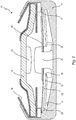
- Fig. 1 shows a schematic side view of a temperature-dependent switch 10, which is circular in plan view and has a temperature-dependent switching mechanism 11 which is arranged in a housing 12.
- the housing 12 comprises a cup-like lower part 14, which is closed by an upper part 15.
- a peripheral shoulder 16 is provided, on which a spacer ring 17 is arranged, on which the upper part 15 rests with intermediate positioning of an insulating film 18.
- the lower part 14 holds the upper part 15 on the peripheral rim 16 by means of its inwardly bent upwardly protruding edge 19.
- the lower part 14 and upper part 15 are manufactured in the shown embodiment from electrically conductive material, which is why the insulating film 18 is provided and electrically insulates the lower part 14 and the upper part 15 with respect to one another.
- a further insulating covering 22 is provided on an outer surface 21 of the upper part 15, whereas a stationary counter contact 24 is arranged on an inner surface 23 of the upper part 15.
- a movable contact part 25 carried by the switching mechanism 11 cooperates with this stationary counter contact 24.
- the switching mechanism 11 comprises a snap-action spring disc 26, which is fixed via its rim 27 between the ring 16 and the lower part 14, such that it produces an electrically conductive connection there.
- a bimetallic snap-action disc28 is provided beneath the snap-action spring disc 26 and has two geometric temperature positions - the low-temperature position shown in Fig. 1 and the high-temperature position shown in Fig. 2 .
- the bimetallic snap-action disc28 lies with its rim 29 freely above a wedge-shaped peripheral shoulder 31, which is formed on an inner base 32 of the lower part 14.
- the lower part 14 also has an outer base 33, which together with the outer surface 21 of the upper part 15 serves as the external connection of the switch 10 from Fig. 1 .
- the bimetallic snap-action disc28 is supported by its centre 35 on a peripheral shoulder 34 of the contact part 25.
- the bimetallic snap-action disc28 presses via its centre 35 against the shoulder 34 and thus lifts the movable contact part 25 from the stationary counter contact 24, as is shown in Fig. 2 .
- the snap-action spring disc 26 may be a bi-stable spring disc, which is also geometrically stable in the position in Fig. 2 , such that the movable contact part 25 then also does not contact the stationary counter contact 24 again if the rim 29 of the bimetallic snap-action disc28 no longer presses against the rim 27 of the snap-action spring disc 26.
- This spring part is the snap-action spring disc 26 in the present embodiment, wherein, instead of the snap-action spring disc 26, merely the bimetallic snap-action disc28 may also be provided, which then for example would be fixed by its rim 29 beneath the peripheral ring 16, although this is not necessary.
- an arc-shielding plate 38 is arranged on the snap-action spring disc 26, more specifically on its upper surface 37 facing the stationary counter contact 24, and is electrically conductively connected to the movable contact part 25, but mechanically is devoid of function.
- the arc-shielding plate 38 is a part stamped from a copper sheet having a thickness of 0.05 mm, such that it performs no spring function at all and does not mechanically load or impair the switching movement of the switching mechanism 11.
- This arc-shielding plate 38 nevertheless causes both the switched current intensity and the life period of the switch 10 to be considerably increased compared to a switch of identical design, but without an arc-shielding plate 38.
- the movable contact part 25 has a pin 39, onto which a ring 40 is pressed, such that both the snap-action spring disc 26 and the arc-shielding plate 38 are fixed between the ring 40 and the contact part 25.
- the shoulder 34 on which the centre 35 of the bimetallic snap-action disc28 rests is formed on the ring 40.
- Fig. 3 shows a plan view of the temperature-dependent switching mechanism 11 from the switch 10 according to Figs. 1 and 2 .
- the arc-shielding plate 38 covers an annular area 41 on the upper surface 37 around the movable contact part 25, said annular area having a width 42 that is approximately 30% of the diameter 43 of the movable contact part 25.
- the closed annular area 41 bears directly against the movable contact part 25 because the arc-shielding plate 38 has an annular region 44 which is illustrated in a dotted manner in Fig. 3 and extends beneath the movable contact part 25, where it has a through-opening 45, of which the diameter 46 corresponds to the diameter of the pin 39 of the movable contact part 25.
- the dotted annular region 44 has a width indicated at 47 that is smaller than the diameter 46 of the contact part 25.
- a strip 49 of the arc-shielding plate 38 extends from the annular region 44 to a rim 48 in the direction of the edge 27 of the snap-action spring disc 26.
- the arrangement is selected such that the rim 48 is set back so far from the rim 27 that the arc-shielding plate does not reach as far as the spacer ring 17, as can be seen in Fig. 1 .
- Fig. 4 in an illustration similar to Fig. 3 , shows the switching mechanism 11 with a further embodiment for the arc-shielding plate 38'.
- the annular region 44 can again be seen around the movable contact part 25, a first strip 49 now extending to the right from said annular region to the rim 38 and a strip 51 now extending to the left from said annular region to a rim 52 which, similarly to the rim 48, does not reach as far as the rim 27 of the snap-action spring disc 26.
- the covered area of the upper surface 37 is enlarged by the arc-shielding plate 38' to approximately 40% compared with the embodiment according to Fig. 3 , which leads to better protection still.
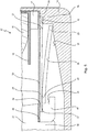
- the arc-shielding plate 38, 38' is indeed electrically connected to the movable contact part 25, but does not reach beyond the snap-action spring disc 26, an embodiment is shown in Fig. 5 in which the arc-shielding plate 38" is also electrically conductively connected to the second counter contact, that is to say the lower part 14.
- a temperature-dependent switch 10' is shown in part in Fig. 5 and for the rest is constructed similarly to the switch 10 from Figs. 1 and 2 . The differences will be explained below.
- a recess 54 is provided in the spacer ring 17 and is designed such that an end 55 of the arc-shielding plate 38" protrudes there, such that it is fixed between the spacer ring 17 and lower part 14.
- the snap-action spring disc 26 now rests via its centre 56 on a shoulder 57 of the ring 40, that is to say is no longer securely fixed between the movable contact part 25 and the ring 40.
- the arc-shielding plate 38" is fixed via its centre 58 between the movable contact part 25 and the ring 40.
- the arc-shielding plate 38" is thus electrically connected both to the movable contact part 25 and to the lower part 14, that is to say the second counter contact of the switch 10'.
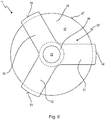
- FIG. 6 A plan view of the switching mechanism 11' from the switch 10' according to Fig. 5 is shown in Fig. 6 .
- the arc-shielding plate 38" again comprises the annular region 44, which extends beneath the movable contact part 25.
- Three strips 61, 62, 63 proceed in a star-shaped manner from this annular region 44, the rims 64, 65, 66 of said strips protruding beyond the rim 27 of the snap-action spring disc 26, such that they reach into the recess 54 in the spacer ring 17.
Landscapes
- Physics & Mathematics (AREA)
- Thermal Sciences (AREA)
- Thermally Actuated Switches (AREA)
Applications Claiming Priority (3)
| Application Number | Priority Date | Filing Date | Title |
|---|---|---|---|
| DE102013101393.7A DE102013101393B4 (de) | 2013-02-13 | 2013-02-13 | Temperaturabhängiger Schalter |
| DE202013101153U DE202013101153U1 (de) | 2013-02-13 | 2013-03-18 | Temperaturabhängiger Schalter |
| PCT/EP2014/052618 WO2014124929A1 (en) | 2013-02-13 | 2014-02-11 | Temperature-dependent switch |
Publications (2)
| Publication Number | Publication Date |
|---|---|
| EP2834825A1 EP2834825A1 (en) | 2015-02-11 |
| EP2834825B1 true EP2834825B1 (en) | 2017-04-05 |
Family
ID=48145934
Family Applications (1)
| Application Number | Title | Priority Date | Filing Date |
|---|---|---|---|
| EP14703602.4A Active EP2834825B1 (en) | 2013-02-13 | 2014-02-11 | Temperature-dependent switch |
Country Status (9)
| Country | Link |
|---|---|
| US (1) | US9640351B2 (pl) |
| EP (1) | EP2834825B1 (pl) |
| JP (1) | JP6220897B2 (pl) |
| CN (1) | CN104350564B (pl) |
| DE (2) | DE102013101393B4 (pl) |
| DK (1) | DK2834825T3 (pl) |
| ES (1) | ES2627229T3 (pl) |
| PL (1) | PL2834825T3 (pl) |
| WO (1) | WO2014124929A1 (pl) |
Families Citing this family (11)
| Publication number | Priority date | Publication date | Assignee | Title |
|---|---|---|---|---|
| DE102011101862B4 (de) * | 2011-05-12 | 2012-12-13 | Thermik Gerätebau GmbH | Temperaturabhängiger Schalter mit Stromübertragungsglied |
| DE102013017232A1 (de) | 2013-10-17 | 2015-04-23 | Thermik Gerätebau GmbH | Temperaturabhängiges Schaltwerk |
| GB2576898B (en) * | 2018-09-05 | 2021-01-06 | Strix Ltd | Control arrangements for liquid heating appliances |
| DE102019125450B4 (de) * | 2019-09-20 | 2021-04-08 | Marcel P. HOFSAESS | Temperaturabhängiger Schalter |
| DE102019125452B4 (de) * | 2019-09-20 | 2021-04-22 | Marcel P. HOFSAESS | Temperaturabhängiger Schalter |
| IT202100018779A1 (it) * | 2021-07-15 | 2023-01-15 | Miotti S R L | Dispositivo limitatore di temperatura |
| CN113571378A (zh) * | 2021-07-23 | 2021-10-29 | 江苏常荣电器股份有限公司 | 一种新型热传感保护器 |
| DE102022118402B3 (de) | 2022-07-22 | 2023-08-24 | Marcel P. HOFSAESS | Temperaturabhängiges Schaltwerk, temperaturabhängiger Schalter und Verfahren zur Herstellung eines temperaturabhängigen Schaltwerks |
| DE102023104836B3 (de) * | 2023-02-28 | 2024-05-16 | Marcel P. HOFSAESS | Temperaturabhängiges Schaltwerk und temperaturabhängiger Schalter |
| DE102023127594B3 (de) * | 2023-10-10 | 2025-02-13 | Marcel P. HOFSAESS | Temperaturabhängiger Schalter |
| CN119208106B (zh) * | 2024-11-25 | 2025-04-01 | 佛山市九龙机器有限公司 | 一种带磁吹及多重保护的限温器 |
Family Cites Families (21)
| Publication number | Priority date | Publication date | Assignee | Title |
|---|---|---|---|---|
| CH256225A (de) | 1945-11-07 | 1948-08-15 | Ganz & Buesser | Siebvorrichtung. |
| DE977187C (de) | 1954-09-25 | 1965-05-20 | Alfred Odenwald | Klein-Thermoschalter |
| US3416115A (en) * | 1965-12-30 | 1968-12-10 | Texas Instruments Inc | Thermostatic switch with improved capacity and automatic calibration |
| US3355563A (en) * | 1966-08-11 | 1967-11-28 | Texas Instruments Inc | Lost motion thermostatic electrical switch |
| US3564185A (en) * | 1969-02-24 | 1971-02-16 | Robertshaw Controls Co | Electrical switch construction with shield |
| DE2121802C3 (de) | 1971-05-03 | 1974-10-24 | Thermik-Geraetebau Gmbh + Co, 7530 Pforzheim | Temperaturwächter |
| US3902149A (en) * | 1974-10-07 | 1975-08-26 | Texas Instruments Inc | Motor protector apparatus |
| JPS547179A (en) * | 1977-06-18 | 1979-01-19 | Susumu Ubukata | Thermal switch |
| DE2917482C2 (de) * | 1979-04-30 | 1982-11-25 | Peter 7530 Pforzheim Hofsäss | Übertemperaturschutzschalter |
| DE3122899C2 (de) * | 1981-06-10 | 1984-10-11 | Peter 7530 Pforzheim Hofsäss | Temperaturschalter |
| US4551701A (en) * | 1984-05-17 | 1985-11-05 | Susumu Ubukata | Thermally actuated switching device |
| JPS6149937U (pl) * | 1985-07-15 | 1986-04-03 | ||
| JP2519549B2 (ja) * | 1989-12-26 | 1996-07-31 | 生方 眞哉 | 熱応動開閉器 |
| US5337036A (en) * | 1993-07-28 | 1994-08-09 | Kuczynski Robert A | Miniaturized thermal protector with precalibrated automatic resetting bimetallic assembly |
| DE4428226C1 (de) * | 1994-08-10 | 1995-10-12 | Thermik Geraetebau Gmbh | Temperaturwächter |
| DE19604939C2 (de) * | 1996-02-10 | 1999-12-09 | Marcel Hofsaes | Schalter mit einem temperaturabhängigen Schaltwerk |
| DE19609577C2 (de) * | 1996-03-12 | 1998-02-19 | Thermik Geraetebau Gmbh | Schalter mit einem temperaturabhängigen Schaltwerk |
| DE19623570C2 (de) | 1996-06-13 | 1998-05-28 | Marcel Hofsaes | Temperaturwächter mit einer Kaptonfolie |
| DE19816807C2 (de) | 1998-04-16 | 2000-06-08 | Thermik Geraetebau Gmbh | Temperaturabhängiger Schalter |
| CN101162664A (zh) * | 2007-10-19 | 2008-04-16 | 常州市恒立继电器厂 | 微型温控器 |
| DE102012103306B3 (de) * | 2012-04-17 | 2013-04-25 | Thermik Gerätebau GmbH | Temperaturabhängiger Schalter mit Kontaktteil als Heizwiderstand |
-
2013
- 2013-02-13 DE DE102013101393.7A patent/DE102013101393B4/de active Active
- 2013-03-18 DE DE202013101153U patent/DE202013101153U1/de not_active Expired - Lifetime
-
2014
- 2014-02-11 EP EP14703602.4A patent/EP2834825B1/en active Active
- 2014-02-11 JP JP2015556529A patent/JP6220897B2/ja not_active Expired - Fee Related
- 2014-02-11 CN CN201480001477.XA patent/CN104350564B/zh not_active Expired - Fee Related
- 2014-02-11 DK DK14703602.4T patent/DK2834825T3/en active
- 2014-02-11 PL PL14703602T patent/PL2834825T3/pl unknown
- 2014-02-11 ES ES14703602.4T patent/ES2627229T3/es active Active
- 2014-02-11 WO PCT/EP2014/052618 patent/WO2014124929A1/en not_active Ceased
- 2014-11-20 US US14/548,358 patent/US9640351B2/en not_active Expired - Fee Related
Also Published As
| Publication number | Publication date |
|---|---|
| DE102013101393B4 (de) | 2014-10-09 |
| DE202013101153U1 (de) | 2013-03-27 |
| US9640351B2 (en) | 2017-05-02 |
| DK2834825T3 (en) | 2017-06-19 |
| PL2834825T3 (pl) | 2017-09-29 |
| WO2014124929A1 (en) | 2014-08-21 |
| CN104350564A (zh) | 2015-02-11 |
| CN104350564B (zh) | 2019-06-07 |
| JP6220897B2 (ja) | 2017-10-25 |
| EP2834825A1 (en) | 2015-02-11 |
| DE102013101393A1 (de) | 2014-08-14 |
| ES2627229T3 (es) | 2017-07-27 |
| JP2016507141A (ja) | 2016-03-07 |
| US20150077213A1 (en) | 2015-03-19 |
Similar Documents
| Publication | Publication Date | Title |
|---|---|---|
| EP2834825B1 (en) | Temperature-dependent switch | |
| EP2767999A1 (en) | Temperature-dependent switch | |
| US10256061B2 (en) | Temperature-dependent switching mechanism | |
| US9697974B2 (en) | Temperature-dependent switch comprising a spacer ring | |
| DK2846344T3 (en) | Thermal contact | |
| US9263879B2 (en) | Thermal protection circuit | |
| US5023744A (en) | Temperature switching device | |
| EP2597668B1 (en) | Temperature-dependent switching mechanism | |
| CN110047698B (zh) | 温控开关 | |
| US11476066B2 (en) | Temperature-dependent switch | |
| EP2164087A2 (en) | Temperature-dependent switch | |
| DK2854149T3 (en) | Temperature dependent switch with snap disc clamped to the edge | |
| DK2775495T3 (en) | Thermal contact with the insulation washer | |
| EP2654054A1 (en) | Temperature-dependent switch with contact part as heating resistor | |
| US20120126930A1 (en) | Bimetal part and temperature-dependent switch equipped therewith | |
| CN112768292B (zh) | 温控开关 | |
| CN109360770B (zh) | 具有切割刺的温控开关 | |
| CN103946945A (zh) | 温控的接通机构 | |
| JPS60232630A (ja) | バイメタル保護スイツチ | |
| US20240290561A1 (en) | Temperature-dependent switch | |
| HK1206483B (en) | Temperature-dependent switching device | |
| HK1214031B (en) | Temperature-dependent switch with a spacer ring | |
| HK1142167A (en) | Temperature-dependent switch | |
| HK1170333A (en) | Temperature-dependent circuit with power transmission element |
Legal Events
| Date | Code | Title | Description |
|---|---|---|---|
| PUAI | Public reference made under article 153(3) epc to a published international application that has entered the european phase |
Free format text: ORIGINAL CODE: 0009012 |
|
| 17P | Request for examination filed |
Effective date: 20141103 |
|
| AK | Designated contracting states |
Kind code of ref document: A1 Designated state(s): AL AT BE BG CH CY CZ DE DK EE ES FI FR GB GR HR HU IE IS IT LI LT LU LV MC MK MT NL NO PL PT RO RS SE SI SK SM TR |
|
| AX | Request for extension of the european patent |
Extension state: BA ME |
|
| DAX | Request for extension of the european patent (deleted) | ||
| GRAP | Despatch of communication of intention to grant a patent |
Free format text: ORIGINAL CODE: EPIDOSNIGR1 |
|
| INTG | Intention to grant announced |
Effective date: 20161031 |
|
| GRAS | Grant fee paid |
Free format text: ORIGINAL CODE: EPIDOSNIGR3 |
|
| GRAA | (expected) grant |
Free format text: ORIGINAL CODE: 0009210 |
|
| AK | Designated contracting states |
Kind code of ref document: B1 Designated state(s): AL AT BE BG CH CY CZ DE DK EE ES FI FR GB GR HR HU IE IS IT LI LT LU LV MC MK MT NL NO PL PT RO RS SE SI SK SM TR |
|
| REG | Reference to a national code |
Ref country code: GB Ref legal event code: FG4D |
|
| REG | Reference to a national code |
Ref country code: CH Ref legal event code: EP |
|
| REG | Reference to a national code |
Ref country code: AT Ref legal event code: REF Ref document number: 882500 Country of ref document: AT Kind code of ref document: T Effective date: 20170415 |
|
| REG | Reference to a national code |
Ref country code: IE Ref legal event code: FG4D |
|
| REG | Reference to a national code |
Ref country code: DE Ref legal event code: R096 Ref document number: 602014008296 Country of ref document: DE |
|
| REG | Reference to a national code |
Ref country code: NL Ref legal event code: FP |
|
| REG | Reference to a national code |
Ref country code: CH Ref legal event code: NV Representative=s name: RENTSCH PARTNER AG, CH |
|
| REG | Reference to a national code |
Ref country code: DK Ref legal event code: T3 Effective date: 20170613 |
|
| REG | Reference to a national code |
Ref country code: SE Ref legal event code: TRGR |
|
| REG | Reference to a national code |
Ref country code: ES Ref legal event code: FG2A Ref document number: 2627229 Country of ref document: ES Kind code of ref document: T3 Effective date: 20170727 |
|
| REG | Reference to a national code |
Ref country code: LT Ref legal event code: MG4D |
|
| REG | Reference to a national code |
Ref country code: CH Ref legal event code: PCAR Free format text: NEW ADDRESS: BELLERIVESTRASSE 203 POSTFACH, 8034 ZUERICH (CH) |
|
| PG25 | Lapsed in a contracting state [announced via postgrant information from national office to epo] |
Ref country code: FI Free format text: LAPSE BECAUSE OF FAILURE TO SUBMIT A TRANSLATION OF THE DESCRIPTION OR TO PAY THE FEE WITHIN THE PRESCRIBED TIME-LIMIT Effective date: 20170405 Ref country code: NO Free format text: LAPSE BECAUSE OF FAILURE TO SUBMIT A TRANSLATION OF THE DESCRIPTION OR TO PAY THE FEE WITHIN THE PRESCRIBED TIME-LIMIT Effective date: 20170705 Ref country code: LT Free format text: LAPSE BECAUSE OF FAILURE TO SUBMIT A TRANSLATION OF THE DESCRIPTION OR TO PAY THE FEE WITHIN THE PRESCRIBED TIME-LIMIT Effective date: 20170405 Ref country code: HR Free format text: LAPSE BECAUSE OF FAILURE TO SUBMIT A TRANSLATION OF THE DESCRIPTION OR TO PAY THE FEE WITHIN THE PRESCRIBED TIME-LIMIT Effective date: 20170405 Ref country code: GR Free format text: LAPSE BECAUSE OF FAILURE TO SUBMIT A TRANSLATION OF THE DESCRIPTION OR TO PAY THE FEE WITHIN THE PRESCRIBED TIME-LIMIT Effective date: 20170706 |
|
| PG25 | Lapsed in a contracting state [announced via postgrant information from national office to epo] |
Ref country code: IS Free format text: LAPSE BECAUSE OF FAILURE TO SUBMIT A TRANSLATION OF THE DESCRIPTION OR TO PAY THE FEE WITHIN THE PRESCRIBED TIME-LIMIT Effective date: 20170805 Ref country code: RS Free format text: LAPSE BECAUSE OF FAILURE TO SUBMIT A TRANSLATION OF THE DESCRIPTION OR TO PAY THE FEE WITHIN THE PRESCRIBED TIME-LIMIT Effective date: 20170405 Ref country code: LV Free format text: LAPSE BECAUSE OF FAILURE TO SUBMIT A TRANSLATION OF THE DESCRIPTION OR TO PAY THE FEE WITHIN THE PRESCRIBED TIME-LIMIT Effective date: 20170405 Ref country code: BG Free format text: LAPSE BECAUSE OF FAILURE TO SUBMIT A TRANSLATION OF THE DESCRIPTION OR TO PAY THE FEE WITHIN THE PRESCRIBED TIME-LIMIT Effective date: 20170705 |
|
| REG | Reference to a national code |
Ref country code: DE Ref legal event code: R097 Ref document number: 602014008296 Country of ref document: DE |
|
| PG25 | Lapsed in a contracting state [announced via postgrant information from national office to epo] |
Ref country code: RO Free format text: LAPSE BECAUSE OF FAILURE TO SUBMIT A TRANSLATION OF THE DESCRIPTION OR TO PAY THE FEE WITHIN THE PRESCRIBED TIME-LIMIT Effective date: 20170405 Ref country code: SK Free format text: LAPSE BECAUSE OF FAILURE TO SUBMIT A TRANSLATION OF THE DESCRIPTION OR TO PAY THE FEE WITHIN THE PRESCRIBED TIME-LIMIT Effective date: 20170405 Ref country code: CZ Free format text: LAPSE BECAUSE OF FAILURE TO SUBMIT A TRANSLATION OF THE DESCRIPTION OR TO PAY THE FEE WITHIN THE PRESCRIBED TIME-LIMIT Effective date: 20170405 Ref country code: EE Free format text: LAPSE BECAUSE OF FAILURE TO SUBMIT A TRANSLATION OF THE DESCRIPTION OR TO PAY THE FEE WITHIN THE PRESCRIBED TIME-LIMIT Effective date: 20170405 |
|
| PLBE | No opposition filed within time limit |
Free format text: ORIGINAL CODE: 0009261 |
|
| STAA | Information on the status of an ep patent application or granted ep patent |
Free format text: STATUS: NO OPPOSITION FILED WITHIN TIME LIMIT |
|
| REG | Reference to a national code |
Ref country code: FR Ref legal event code: PLFP Year of fee payment: 5 |
|
| PG25 | Lapsed in a contracting state [announced via postgrant information from national office to epo] |
Ref country code: SM Free format text: LAPSE BECAUSE OF FAILURE TO SUBMIT A TRANSLATION OF THE DESCRIPTION OR TO PAY THE FEE WITHIN THE PRESCRIBED TIME-LIMIT Effective date: 20170405 |
|
| 26N | No opposition filed |
Effective date: 20180108 |
|
| PGFP | Annual fee paid to national office [announced via postgrant information from national office to epo] |
Ref country code: NL Payment date: 20180216 Year of fee payment: 5 |
|
| PGFP | Annual fee paid to national office [announced via postgrant information from national office to epo] |
Ref country code: DK Payment date: 20180216 Year of fee payment: 5 Ref country code: ES Payment date: 20180327 Year of fee payment: 5 Ref country code: GB Payment date: 20180216 Year of fee payment: 5 |
|
| PG25 | Lapsed in a contracting state [announced via postgrant information from national office to epo] |
Ref country code: SI Free format text: LAPSE BECAUSE OF FAILURE TO SUBMIT A TRANSLATION OF THE DESCRIPTION OR TO PAY THE FEE WITHIN THE PRESCRIBED TIME-LIMIT Effective date: 20170405 |
|
| PGFP | Annual fee paid to national office [announced via postgrant information from national office to epo] |
Ref country code: FR Payment date: 20180223 Year of fee payment: 5 Ref country code: PL Payment date: 20180124 Year of fee payment: 5 Ref country code: SE Payment date: 20180227 Year of fee payment: 5 |
|
| REG | Reference to a national code |
Ref country code: CH Ref legal event code: PL |
|
| PG25 | Lapsed in a contracting state [announced via postgrant information from national office to epo] |
Ref country code: MC Free format text: LAPSE BECAUSE OF FAILURE TO SUBMIT A TRANSLATION OF THE DESCRIPTION OR TO PAY THE FEE WITHIN THE PRESCRIBED TIME-LIMIT Effective date: 20170405 |
|
| REG | Reference to a national code |
Ref country code: BE Ref legal event code: MM Effective date: 20180228 |
|
| PG25 | Lapsed in a contracting state [announced via postgrant information from national office to epo] |
Ref country code: LU Free format text: LAPSE BECAUSE OF NON-PAYMENT OF DUE FEES Effective date: 20180211 Ref country code: CH Free format text: LAPSE BECAUSE OF NON-PAYMENT OF DUE FEES Effective date: 20180228 Ref country code: LI Free format text: LAPSE BECAUSE OF NON-PAYMENT OF DUE FEES Effective date: 20180228 |
|
| REG | Reference to a national code |
Ref country code: IE Ref legal event code: MM4A |
|
| PG25 | Lapsed in a contracting state [announced via postgrant information from national office to epo] |
Ref country code: IE Free format text: LAPSE BECAUSE OF NON-PAYMENT OF DUE FEES Effective date: 20180211 |
|
| PG25 | Lapsed in a contracting state [announced via postgrant information from national office to epo] |
Ref country code: BE Free format text: LAPSE BECAUSE OF NON-PAYMENT OF DUE FEES Effective date: 20180228 |
|
| PGFP | Annual fee paid to national office [announced via postgrant information from national office to epo] |
Ref country code: IT Payment date: 20190225 Year of fee payment: 6 |
|
| REG | Reference to a national code |
Ref country code: AT Ref legal event code: UEP Ref document number: 882500 Country of ref document: AT Kind code of ref document: T Effective date: 20170405 |
|
| REG | Reference to a national code |
Ref country code: DK Ref legal event code: EBP Effective date: 20190228 |
|
| REG | Reference to a national code |
Ref country code: SE Ref legal event code: EUG |
|
| REG | Reference to a national code |
Ref country code: NL Ref legal event code: MM Effective date: 20190301 |
|
| GBPC | Gb: european patent ceased through non-payment of renewal fee |
Effective date: 20190211 |
|
| PG25 | Lapsed in a contracting state [announced via postgrant information from national office to epo] |
Ref country code: SE Free format text: LAPSE BECAUSE OF NON-PAYMENT OF DUE FEES Effective date: 20190212 |
|
| PG25 | Lapsed in a contracting state [announced via postgrant information from national office to epo] |
Ref country code: MT Free format text: LAPSE BECAUSE OF NON-PAYMENT OF DUE FEES Effective date: 20180211 Ref country code: DK Free format text: LAPSE BECAUSE OF NON-PAYMENT OF DUE FEES Effective date: 20190228 Ref country code: GB Free format text: LAPSE BECAUSE OF NON-PAYMENT OF DUE FEES Effective date: 20190211 Ref country code: NL Free format text: LAPSE BECAUSE OF NON-PAYMENT OF DUE FEES Effective date: 20190301 |
|
| PG25 | Lapsed in a contracting state [announced via postgrant information from national office to epo] |
Ref country code: FR Free format text: LAPSE BECAUSE OF NON-PAYMENT OF DUE FEES Effective date: 20190228 |
|
| REG | Reference to a national code |
Ref country code: ES Ref legal event code: FD2A Effective date: 20200327 |
|
| PG25 | Lapsed in a contracting state [announced via postgrant information from national office to epo] |
Ref country code: TR Free format text: LAPSE BECAUSE OF FAILURE TO SUBMIT A TRANSLATION OF THE DESCRIPTION OR TO PAY THE FEE WITHIN THE PRESCRIBED TIME-LIMIT Effective date: 20170405 |
|
| REG | Reference to a national code |
Ref country code: AT Ref legal event code: MM01 Ref document number: 882500 Country of ref document: AT Kind code of ref document: T Effective date: 20190211 |
|
| PG25 | Lapsed in a contracting state [announced via postgrant information from national office to epo] |
Ref country code: ES Free format text: LAPSE BECAUSE OF NON-PAYMENT OF DUE FEES Effective date: 20190212 Ref country code: AT Free format text: LAPSE BECAUSE OF NON-PAYMENT OF DUE FEES Effective date: 20190211 |
|
| PG25 | Lapsed in a contracting state [announced via postgrant information from national office to epo] |
Ref country code: PT Free format text: LAPSE BECAUSE OF FAILURE TO SUBMIT A TRANSLATION OF THE DESCRIPTION OR TO PAY THE FEE WITHIN THE PRESCRIBED TIME-LIMIT Effective date: 20170405 |
|
| PG25 | Lapsed in a contracting state [announced via postgrant information from national office to epo] |
Ref country code: MK Free format text: LAPSE BECAUSE OF NON-PAYMENT OF DUE FEES Effective date: 20170405 Ref country code: HU Free format text: LAPSE BECAUSE OF FAILURE TO SUBMIT A TRANSLATION OF THE DESCRIPTION OR TO PAY THE FEE WITHIN THE PRESCRIBED TIME-LIMIT; INVALID AB INITIO Effective date: 20140211 Ref country code: CY Free format text: LAPSE BECAUSE OF FAILURE TO SUBMIT A TRANSLATION OF THE DESCRIPTION OR TO PAY THE FEE WITHIN THE PRESCRIBED TIME-LIMIT Effective date: 20170405 |
|
| PG25 | Lapsed in a contracting state [announced via postgrant information from national office to epo] |
Ref country code: AL Free format text: LAPSE BECAUSE OF FAILURE TO SUBMIT A TRANSLATION OF THE DESCRIPTION OR TO PAY THE FEE WITHIN THE PRESCRIBED TIME-LIMIT Effective date: 20170405 |
|
| PG25 | Lapsed in a contracting state [announced via postgrant information from national office to epo] |
Ref country code: PL Free format text: LAPSE BECAUSE OF NON-PAYMENT OF DUE FEES Effective date: 20190211 |
|
| PG25 | Lapsed in a contracting state [announced via postgrant information from national office to epo] |
Ref country code: IT Free format text: LAPSE BECAUSE OF NON-PAYMENT OF DUE FEES Effective date: 20200211 |
|
| P01 | Opt-out of the competence of the unified patent court (upc) registered |
Effective date: 20230508 |
|
| PGFP | Annual fee paid to national office [announced via postgrant information from national office to epo] |
Ref country code: DE Payment date: 20260224 Year of fee payment: 13 |