EP2834403B1 - Washing machine, and control method thereof - Google Patents
Washing machine, and control method thereof Download PDFInfo
- Publication number
- EP2834403B1 EP2834403B1 EP13723215.3A EP13723215A EP2834403B1 EP 2834403 B1 EP2834403 B1 EP 2834403B1 EP 13723215 A EP13723215 A EP 13723215A EP 2834403 B1 EP2834403 B1 EP 2834403B1
- Authority
- EP
- European Patent Office
- Prior art keywords
- washing machine
- door lock
- sliding block
- door
- latching part
- Prior art date
- Legal status (The legal status is an assumption and is not a legal conclusion. Google has not performed a legal analysis and makes no representation as to the accuracy of the status listed.)
- Active
Links
- 238000005406 washing Methods 0.000 title claims description 214
- 238000000034 method Methods 0.000 title claims description 11
- XEEYBQQBJWHFJM-UHFFFAOYSA-N Iron Chemical group [Fe] XEEYBQQBJWHFJM-UHFFFAOYSA-N 0.000 claims description 35
- 235000014676 Phragmites communis Nutrition 0.000 claims description 14
- 239000002184 metal Substances 0.000 claims description 14
- 229910052751 metal Inorganic materials 0.000 claims description 14
- 238000001035 drying Methods 0.000 description 6
- 239000003599 detergent Substances 0.000 description 5
- 241000894006 Bacteria Species 0.000 description 3
- 230000018044 dehydration Effects 0.000 description 2
- 238000006297 dehydration reaction Methods 0.000 description 2
- 230000000694 effects Effects 0.000 description 2
- 239000007788 liquid Substances 0.000 description 2
- 239000007769 metal material Substances 0.000 description 2
- 230000009286 beneficial effect Effects 0.000 description 1
- 239000000356 contaminant Substances 0.000 description 1
- 230000001419 dependent effect Effects 0.000 description 1
- 238000010586 diagram Methods 0.000 description 1
- 230000001788 irregular Effects 0.000 description 1
- 230000004048 modification Effects 0.000 description 1
- 238000012986 modification Methods 0.000 description 1
- 239000000843 powder Substances 0.000 description 1
- XLYOFNOQVPJJNP-UHFFFAOYSA-N water Substances O XLYOFNOQVPJJNP-UHFFFAOYSA-N 0.000 description 1
Images

Classifications
-
- D—TEXTILES; PAPER
- D06—TREATMENT OF TEXTILES OR THE LIKE; LAUNDERING; FLEXIBLE MATERIALS NOT OTHERWISE PROVIDED FOR
- D06F—LAUNDERING, DRYING, IRONING, PRESSING OR FOLDING TEXTILE ARTICLES
- D06F37/00—Details specific to washing machines covered by groups D06F21/00 - D06F25/00
- D06F37/42—Safety arrangements, e.g. for stopping rotation of the receptacle upon opening of the casing door
-
- D—TEXTILES; PAPER
- D06—TREATMENT OF TEXTILES OR THE LIKE; LAUNDERING; FLEXIBLE MATERIALS NOT OTHERWISE PROVIDED FOR
- D06F—LAUNDERING, DRYING, IRONING, PRESSING OR FOLDING TEXTILE ARTICLES
- D06F39/00—Details of washing machines not specific to a single type of machines covered by groups D06F9/00 - D06F27/00
- D06F39/12—Casings; Tubs
- D06F39/14—Doors or covers; Securing means therefor
Definitions
- the present invention relates to a washing machine, comprising: a washing machine main body in which a main controller is disposed; a rotatable drum disposed in the washing machine main body and used for accommodating laundry; a washing machine door, connected to a shell of the washing machine main body, and used for closing a laundry input mouth of the rotatable drum formed on the washing machine main body shell; a hook, disposed at one of the washing machine main body shell and the washing machine door; and a door lock device, disposed at the other of the washing machine main body shell and the washing machine door, and used for locking or unlocking the washing machine door in cooperation with the hook, wherein the door lock device comprises: a door lock sliding block, disposed with a clipping hole at one end thereof, and used for latching in cooperation with the hook; a resetting spring disposed on the door lock sliding block, and used for resetting the door lock sliding block to an initial state; and a first latching part and a second latching part used for latching the door lock sliding block, wherein the
- the first latching part comprises a relay component
- the relay component has an electromagnet with a hollow passage, a coil wound around the electromagnet, an iron core and an iron core spring disposed on the iron core, the iron core moves in the hollow passage of the electromagnet by the action of an electromagnetic force and the iron core spring.
- the invention also relates to a control method of such washing machine.
- the invention relates to a washing machine whose door automatically opens and a control method thereof.
- a washing machine is a device in which by the action of water and detergent, in order to remove contaminants stuck to laundry such as clothes, and a quilt cover in a rotary drum, the laundry is cleaned through a series of washing procedures such as washing, cleansing, dehydration, and drying.
- a washing machine generally includes: a shell, forming the outer appearance, and formed with a laundry input mouth at one side; a washing machine door, mounted on the shell, and used for opening/closing the laundry input mouth; a tub, disposed in the washing machine body, and used for being filled with washing liquid; a rotary drum, mounted in the tub in a rotatable manner, and used for accommodating laundry; and a motor, used for rotating the drum.
- a locking switch device is further mounted on the shell and the door of the washing machine, and may lock the washing machine door when the washing machine door should not be opened when the washing machine works.
- washing machine in the prior art, laundry is input through the laundry input mouth, the washing machine door is closed, and a corresponding program such as washing, cleansing, dehydration, or drying is selected, the washing machine starts the washing machine motor or drying device according to the selected corresponding program, and the locking switch device locks the washing machine door in a working state of the washing machine, so as to prevent the washing machine door from being randomly opened.
- a corresponding program such as washing, cleansing, dehydration, or drying
- the washing machine starts the washing machine motor or drying device according to the selected corresponding program
- the locking switch device locks the washing machine door in a working state of the washing machine, so as to prevent the washing machine door from being randomly opened.
- the washing machine after running of any working program ends, if a user does not open the washing machine door in a long time, and the laundry is taken out, the laundry easily generates bacteria and a foul smell in a closed environment, so as to require performing the washing operation again.
- an objective of the present invention lies in that, after washing programs of a washing machine end, a washing machine door can automatically pop open, so as to prevent bacteria or a foul smell from being generated because laundered clothes are left in the washing machine for a long time.
- a washing machine including: a washing machine main body in which a main controller is disposed; a rotatable drum disposed in the washing machine main body and used for accommodating laundry; a washing machine door, connected to a shell of the washing machine main body, and used for closing a laundry input mouth of the rotatable drum formed on the washing machine main body shell; a hook, disposed at one of the washing machine main body shell and the washing machine door; and a door lock device, disposed at the other of the washing machine main body shell and the washing machine door, and used for locking or unlocking the washing machine door in cooperation with the hook, where the door lock device includes: a door lock sliding block, disposed with a clipping hole at one end thereof, and used for latching in cooperation with the hook; a resetting spring disposed on the door lock sliding block, and used for resetting the door lock sliding block to an initial state; and a first latching part and a second latching part used for latching the door lock sliding block, where the first latching part and the second latching part are
- the first latching part includes a relay component, the relay component has an ron core, a coil wound around the iron core and an iron core spring disposed on the iron core, a groove in cooperation with the iron core is disposed on the door lock sliding block, and when the iron core is inserted into the groove, the first latching part latches the door lock sliding block.
- the hook is disposed on the washing machine door
- the door lock device is disposed on the washing machine shell.
- a contact end face of the hook and the door lock sliding block is a smooth curve.
- the door lock device has three states as follows: a first state is an unlocking state, where neither the first latching part nor the second latching part latches the door lock sliding block, and the washing machine door is opened; a second state is a locking state, where the first latching part latches the door lock sliding block while the second latching part does not lock the door lock sliding block, and the washing machine door is closed but is capable of being manually opened; and a third state is a deadlock state, where both the first latching part and the second latching part latch the door lock sliding block, the washing machine works and the washing machine door is deadlocked.
- a longitudinal section of a contact end of the iron core and the door lock sliding block is approximately trapezoidal, and a longitudinal section of the groove is also approximately trapezoidal.
- the second latching part includes a PTC heater, a double-metal reed disposed on the PTC heater and a locking piece disposed on the double-metal reed, a notch in cooperation with the locking piece is disposed on the door lock sliding block, and when the PTC heater is heated so that the double-metal reed is deformed and the locking piece is inserted into the notch, the second latching part latches the door lock sliding block.
- a torsional spring device is disposed on a rotating shaft of the washing machine door, and is used for applying a force popping open outward to the washing machine door after the washing machine door is unlocked.
- the present invention further provides a control method of a washing machine: after washing programs are input and the washing machine is started, the washing machine main controller controls the first latching part and the second latching part to lock the door lock sliding block; after all of the washing programs end, the washing machine main controller controls the first latching part and the second latching part to unlock the door lock sliding block, the door lock sliding block returns to the initial state by the action of the resetting spring, and the washing machine door automatically pops open.
- a preferred development of the invention is as follows: After all of the washing programs end, only through a predetermined time, the washing machine main controller controls the first latching part and the second latching part to unlock the door lock sliding block, and the washing machine door automatically pops open.
- the present invention includes beneficial effects as follows: After all the washing programs end, the washing machine can automatically open the washing machine door, so that after the washing of the laundry is completed, fresh air circulates, so as to avoid bacteria and the foul smell generated by the laundry because the washing machine door is not opened for a long time, and to be free of the trouble of performing the washing operation again.
- a washing machine 100 in an embodiment of the present invention includes: a washing machine main body 10 in which a main controller 13 is disposed; a rotatable drum 60 disposed in the washing machine main body 10 and used for accommodating laundry; a washing machine door 20, connected to a shell 11 of the washing machine main body, and used for closing a laundry input mouth 61 of the rotatable drum 60 formed on the washing machine main body shell 11; a hook 21, disposed at one of the washing machine main body shell 11 and the washing machine door 20; and a door lock device 30, disposed at the other of the washing machine main body shell 11 and the washing machine door 20, and used for locking or unlocking the washing machine door 20 in cooperation with the hook 21, where the door lock device 30 includes: a door lock sliding block 31, disposed with a clipping hole 32 at one end thereof, and used for latching in cooperation with the hook 21; a resetting spring 35 disposed on the door lock sliding block 31, and used for resetting the door lock sliding block 31 to an initial state; and a
- the washing machine main body 10 includes a shell 11, and the shell 11 includes a top face 11a, a bottom face 11b, two side faces 11c, a back face 11d, and a front face 11e.
- all the faces of the shell 11 are made of a conductive metal material, or all other faces except the top face 11 a are made of a metal material. Except that the bottom face 11b and the back face 11 d are uneasily contacted, all other faces are possibly contacted by a user.
- An operation panel area 12a, a detergent box area 12b, and a door and handle area 12c are disposed on the front face 11e of the washing machine main body shell 11, and the user generally performs an operation on these areas according to requirements.
- washing machines differ from each other in locations and settings of the operation areas.
- operation panels of some washing machines are located on the top face
- the door and the handle for a pulsator washing machine are generally located on the top face
- some washing machines have no detergent box.
- shells of some washing machines are not of a regular hexahedron, for example a smoothly transitional curve is formed between the top face and the front face, and may further be of some other irregular three-dimensional structures.
- the operation panel area 12a in the front face 11e of the washing machine main body shell 11 is disposed with a washing machine starting key 70 used for starting the washing machine to work, a program selection key 80 used for selecting a washing machine working program and a display panel 90 used for showing a washing machine working state.
- the detergent box area 12b in the front face 11e is used for storing some washing articles such as washing powder or washing liquid.
- the door and handle area 12c in the front face 11e has a laundry input mouth 61, and meanwhile is mounted with the washing machine door 20 used for closing the laundry input mouth 61.
- a hook 21 is disposed on the washing machine door 20, and correspondingly a door lock device 30 used for locking or unlocking the hook 21 is mounted on the washing machine shell 11, so that the washing machine door 20 may be closed and opened.
- the hook 21 is disposed on the washing machine shell 11, while the door lock device 30is mounted on the washing machine door 20, so the effect of locking or unlocking the washing machine door 20 may be achieved likewise.
- the door lock device 30 includes: A door lock sliding block 31, disposed with a clipping hole 32 at one end thereof, and used for latching in cooperation with the hook 21; a resetting spring 35 disposed on the door lock sliding block 31, and used for resetting the door lock sliding block 31 to an initial state; and a first latching part 40 and a second latching part 50 used for latching the door lock sliding block 31.
- a groove 33 used for accepting the first latching part 40 and a notch used for accepting the second latching part 50 are separately disposed on the door lock sliding block 31.
- One end of the resetting spring 35 is connected to the door lock sliding block 31, and the other end is connected to the washing machine shell 11.
- the first latching part 40 includes a relay component, the relay component has an electromagnet 42 with a hollow passage, a coil 43 wound around the electromagnet 42, an iron core 41 and an iron core spring 44 disposed on the iron core, and the iron core 41 moves in the hollow passage of the electromagnet by the action of an electromagnetic force and the iron core spring 44.
- the second latching part 50 includes a PTC heater 51, a double-metal reed 52 disposed on the PTC heater 51 and a locking piece 53 disposed on the double-metal reed 52.
- the door lock device 30 includes three states as follows: a first state is an unlocking state, where as shown in FIG. 2 , the iron core 41 abuts against the door lock sliding block 31 and is not inserted into the groove 33, the iron core spring 44 is in a shrinkage state, the PTC heater is not power-on, the double-metal reed 52 is not deformed, and the locking piece 53 is not inserted into the notch 34, so neither the first latching part 40 nor the second latching part 50 latches the door lock sliding block 31, and at this time the washing machine door 20 is opened.
- a first state is an unlocking state, where as shown in FIG. 2 , the iron core 41 abuts against the door lock sliding block 31 and is not inserted into the groove 33, the iron core spring 44 is in a shrinkage state, the PTC heater is not power-on, the double-metal reed 52 is not deformed, and the locking piece 53 is not inserted into the notch 34, so neither the first latching part 40 nor the second
- a second state is a locking state, where as shown in FIG. 3 , when the washing machine door 20 is closed, the hook 21 is inserted into the clipping hole 32 and interacts with the door lock sliding block 31, so the door lock sliding block 31 moves and compresses the resetting spring 35 to shrink the resetting spring 35; as the door lock sliding block 31 moves, the iron core 41 is slowly inserted into the groove 33, the iron core spring 44 is restored to the natural state, the iron core 41 is inserted into the groove 33, and at this time the first latching part 40 latches the door lock sliding block 31 while the second latching part 50 does not lock the door lock sliding block 31, the washing machine door 20 is closed but is not deadlock, and the user may still open the washing machine door 20; a longitudinal section of a contact end of the iron core 41 and the door lock sliding block 31 is approximately trapezoidal, and a longitudinal section of the groove 33 is also approximately trapezoidal; in such design, in the state, when the washing machine door is opened with an external force, the iron core 41 is very easily separated from
- a third state is a deadlock state, where as shown in FIG. 4 , in a case of the second state, when the washing machine works and the washing machine main controller 13 controls the second latching part 50 to work, the PTC heater is heated so that the double-metal reed 52 is deformed, the locking piece 53 disposed on the double-metal reed 52 is inserted into the notch 34 accordingly, and at this time, both the first latching part 40 and the second latching part 50 latch the door lock sliding block 31, the washing machine works and the washing machine door is deadlock.
- the washing machine main controller 13 controls the first latching part 40 and the second latching part 50 to unlock the door lock sliding block 31, the iron core 41 is separated from the groove 33 by the action of an electromagnetic force, the locking piece 53 slowly quits the notch 34 as the double-metal reed 52 is restored to the original state, the door lock sliding block 31 returns to the initial state by the action of the resetting spring 35, and the washing machine door 20 automatically pops open.
- a contact end face of the hook 21 and the door lock sliding block 31 is a smooth curve, and in the procedure that the washing machine door 20 automatically pops open, the hook 21 is smoothly separated from the clipping hole 32 under the pushing of the door lock sliding block 31, so that the washing machine door smoothly pops open.
- a torsional spring device is disposed on the rotating shaft 22 of the washing machine door, and is used for applying a force popping open outward to the washing machine door 20 after the washing machine door 20 is unlocked.
- the washing machine main controller 13 controls the first latching part 40 and the second latching part 50 to lock the door lock sliding block 31; after all of the washing programs end, the washing machine main controller 13 controls the first latching part 40 and the second latching part 50 to unlock the door lock sliding block 31, the door lock sliding block 31 returns to the initial state by the action of the resetting spring 35, and the washing machine door 20 automatically pops open.
- the washing machine main controller 13 may control the first latching part 40 and the second latching part 50 to unlock the door lock sliding block 31 in a predetermined time, generally one minute, and at this time the washing machine door 20 automatically pops open.
Landscapes
- Engineering & Computer Science (AREA)
- Textile Engineering (AREA)
- Main Body Construction Of Washing Machines And Laundry Dryers (AREA)
Description
- The present invention relates to a washing machine, comprising: a washing machine main body in which a main controller is disposed; a rotatable drum disposed in the washing machine main body and used for accommodating laundry; a washing machine door, connected to a shell of the washing machine main body, and used for closing a laundry input mouth of the rotatable drum formed on the washing machine main body shell; a hook, disposed at one of the washing machine main body shell and the washing machine door; and a door lock device, disposed at the other of the washing machine main body shell and the washing machine door, and used for locking or unlocking the washing machine door in cooperation with the hook, wherein the door lock device comprises: a door lock sliding block, disposed with a clipping hole at one end thereof, and used for latching in cooperation with the hook; a resetting spring disposed on the door lock sliding block, and used for resetting the door lock sliding block to an initial state; and a first latching part and a second latching part used for latching the door lock sliding block, wherein the first latching part and the second latching part are both controlled by the washing machine main controller; after washing of the washing machine ends, the washing machine main controller controls the first latching part and the second latching part to unlock the door lock sliding block, the door lock sliding block is restored to the initial state by the action of the resetting spring, and the hook is separated from the door lock device by the action of the door lock sliding block to automatically open the washing machine door. Further, the first latching part comprises a relay component, the relay component has an electromagnet with a hollow passage, a coil wound around the electromagnet, an iron core and an iron core spring disposed on the iron core, the iron core moves in the hollow passage of the electromagnet by the action of an electromagnetic force and the iron core spring. The invention also relates to a control method of such washing machine.
- Particularly the invention relates to a washing machine whose door automatically opens and a control method thereof.
- Such washing machine and control method are disclosed in
EP 0 588 041 A1 . - A washing machine is a device in which by the action of water and detergent, in order to remove contaminants stuck to laundry such as clothes, and a quilt cover in a rotary drum, the laundry is cleaned through a series of washing procedures such as washing, cleansing, dehydration, and drying. A washing machine generally includes: a shell, forming the outer appearance, and formed with a laundry input mouth at one side; a washing machine door, mounted on the shell, and used for opening/closing the laundry input mouth; a tub, disposed in the washing machine body, and used for being filled with washing liquid; a rotary drum, mounted in the tub in a rotatable manner, and used for accommodating laundry; and a motor, used for rotating the drum. Moreover, a locking switch device is further mounted on the shell and the door of the washing machine, and may lock the washing machine door when the washing machine door should not be opened when the washing machine works.
- According to the washing machine in the prior art, laundry is input through the laundry input mouth, the washing machine door is closed, and a corresponding program such as washing, cleansing, dehydration, or drying is selected, the washing machine starts the washing machine motor or drying device according to the selected corresponding program, and the locking switch device locks the washing machine door in a working state of the washing machine, so as to prevent the washing machine door from being randomly opened. For the washing machine, after running of any working program ends, if a user does not open the washing machine door in a long time, and the laundry is taken out, the laundry easily generates bacteria and a foul smell in a closed environment, so as to require performing the washing operation again.
- Aiming at the above problem, an objective of the present invention lies in that, after washing programs of a washing machine end, a washing machine door can automatically pop open, so as to prevent bacteria or a foul smell from being generated because laundered clothes are left in the washing machine for a long time.
- Aiming at the above objective, the technical solution adopted in the present invention is as defined in the attached independent claims. Preferred embodiments of the invention are defined in dependent claims, the subsequent description and the attached drawing. Preferred embodiments of the inventive washing machine correspond to preferred embodiments of the inventive method and vice versa, and this even if not indicated expressly herein.
- Accordingly, a technical solution provided by the invention is as follows:
- A washing machine, including: a washing machine main body in which a main controller is disposed; a rotatable drum disposed in the washing machine main body and used for accommodating laundry; a washing machine door, connected to a shell of the washing machine main body, and used for closing a laundry input mouth of the rotatable drum formed on the washing machine main body shell; a hook, disposed at one of the washing machine main body shell and the washing machine door; and a door lock device, disposed at the other of the washing machine main body shell and the washing machine door, and used for locking or unlocking the washing machine door in cooperation with the hook, where the door lock device includes: a door lock sliding block, disposed with a clipping hole at one end thereof, and used for latching in cooperation with the hook; a resetting spring disposed on the door lock sliding block, and used for resetting the door lock sliding block to an initial state; and a first latching part and a second latching part used for latching the door lock sliding block, where the first latching part and the second latching part are both controlled by the washing machine main controller; after washing of the washing machine ends, the washing machine main controller controls the first latching part and the second latching part to unlock the door lock sliding block, the door lock sliding block is restored to the initial state by the action of the resetting spring, and the hook is separated from the door lock device by the action of the door lock sliding block to automatically open the washing machine door. In addition, the first latching part includes a relay component, the relay component has an ron core, a coil wound around the iron core and an iron core spring disposed on the iron core, a groove in cooperation with the iron core is disposed on the door lock sliding block, and when the iron core is inserted into the groove, the first latching part latches the door lock sliding block.
- As a preferred development of the present invention, the hook is disposed on the washing machine door, and the door lock device is disposed on the washing machine shell.
- As another preferred development of the present invention, a contact end face of the hook and the door lock sliding block is a smooth curve.
- As a further preferred development of the present invention, the door lock device has three states as follows: a first state is an unlocking state, where neither the first latching part nor the second latching part latches the door lock sliding block, and the washing machine door is opened; a second state is a locking state, where the first latching part latches the door lock sliding block while the second latching part does not lock the door lock sliding block, and the washing machine door is closed but is capable of being manually opened; and a third state is a deadlock state, where both the first latching part and the second latching part latch the door lock sliding block, the washing machine works and the washing machine door is deadlocked.
- As even a further preferred development of the present invention, a longitudinal section of a contact end of the iron core and the door lock sliding block is approximately trapezoidal, and a longitudinal section of the groove is also approximately trapezoidal.
- As yet another preferred development of the present invention, the second latching part includes a PTC heater, a double-metal reed disposed on the PTC heater and a locking piece disposed on the double-metal reed, a notch in cooperation with the locking piece is disposed on the door lock sliding block, and when the PTC heater is heated so that the double-metal reed is deformed and the locking piece is inserted into the notch, the second latching part latches the door lock sliding block.
- As yet a further preferred development of the present invention, a torsional spring device is disposed on a rotating shaft of the washing machine door, and is used for applying a force popping open outward to the washing machine door after the washing machine door is unlocked.
- Moreover, the present invention further provides a control method of a washing machine: after washing programs are input and the washing machine is started, the washing machine main controller controls the first latching part and the second latching part to lock the door lock sliding block; after all of the washing programs end, the washing machine main controller controls the first latching part and the second latching part to unlock the door lock sliding block, the door lock sliding block returns to the initial state by the action of the resetting spring, and the washing machine door automatically pops open.
- A preferred development of the invention is as follows: After all of the washing programs end, only through a predetermined time, the washing machine main controller controls the first latching part and the second latching part to unlock the door lock sliding block, and the washing machine door automatically pops open.
- Compared with the prior art, the present invention includes beneficial effects as follows: After all the washing programs end, the washing machine can automatically open the washing machine door, so that after the washing of the laundry is completed, fresh air circulates, so as to avoid bacteria and the foul smell generated by the laundry because the washing machine door is not opened for a long time, and to be free of the trouble of performing the washing operation again.
- Preferred embodiments of the invention are now explained in detail with reference to the Figures of the attached drawing. The implementation manners of the several washing machines are not shown in the accompanying drawings, but can doubtless be understood by persons of ordinary skill in the art through the above description. Additionally, other washing machines not specifically described above including a washing machine without drying function, a drying machine, a washing and drying machine, and other household washing machines fall within the protection scope of the present invention .In the drawing,
-
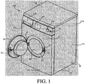
FIG. 1 is a three-dimensional diagram of a washing machine; -
FIG. 2 shows a door lock device in an unlocking state; -
FIG. 3 shows the door lock device ofFIG. 2 in a locking state; and -
FIG. 4 shows the door lock device ofFIG. 2 in a deadlock state. - As shown in
FIG. 1 , awashing machine 100 in an embodiment of the present invention includes: a washing machinemain body 10 in which a main controller 13 is disposed; arotatable drum 60 disposed in the washing machinemain body 10 and used for accommodating laundry; awashing machine door 20, connected to a shell 11 of the washing machine main body, and used for closing a laundry input mouth 61 of therotatable drum 60 formed on the washing machine main body shell 11; ahook 21, disposed at one of the washing machine main body shell 11 and thewashing machine door 20; and adoor lock device 30, disposed at the other of the washing machine main body shell 11 and thewashing machine door 20, and used for locking or unlocking thewashing machine door 20 in cooperation with thehook 21, where thedoor lock device 30 includes: a doorlock sliding block 31, disposed with aclipping hole 32 at one end thereof, and used for latching in cooperation with thehook 21; a resettingspring 35 disposed on the doorlock sliding block 31, and used for resetting the doorlock sliding block 31 to an initial state; and afirst latching part 40 and asecond latching part 50 used for latching the doorlock sliding block 31, where thefirst latching part 40 and the secondlatching part 50 are both controlled by the washing machine main controller 13; after washing of the washing machine ends, the washing machine main controller 13 controls thefirst latching part 40 and thesecond latching part 50 to unlock the doorlock sliding block 31, the doorlock sliding block 31 is restored to the initial state by the action of the resettingspring 35, and thehook 21 is separated from thedoor lock device 30 by the action of the doorlock sliding block 31 to automatically open thewashing machine door 20. - The washing machine
main body 10 includes a shell 11, and the shell 11 includes a top face 11a, abottom face 11b, two side faces 11c, a back face 11d, and a front face 11e. In most cases, all the faces of the shell 11 are made of a conductive metal material, or all other faces except the top face 11 a are made of a metal material. Except that thebottom face 11b and the back face 11 d are uneasily contacted, all other faces are possibly contacted by a user. An operation panel area 12a, a detergent box area 12b, and a door andhandle area 12c are disposed on the front face 11e of the washing machine main body shell 11, and the user generally performs an operation on these areas according to requirements. Different styles or types of washing machines differ from each other in locations and settings of the operation areas. For example, operation panels of some washing machines are located on the top face, the door and the handle for a pulsator washing machine are generally located on the top face, and some washing machines have no detergent box. Additionally, shells of some washing machines are not of a regular hexahedron, for example a smoothly transitional curve is formed between the top face and the front face, and may further be of some other irregular three-dimensional structures. - As shown in
FIG. 1 , the operation panel area 12a in the front face 11e of the washing machine main body shell 11 is disposed with a washing machine starting key 70 used for starting the washing machine to work, a program selection key 80 used for selecting a washing machine working program and adisplay panel 90 used for showing a washing machine working state. The detergent box area 12b in the front face 11e is used for storing some washing articles such as washing powder or washing liquid. The door andhandle area 12c in the front face 11e has a laundry input mouth 61, and meanwhile is mounted with thewashing machine door 20 used for closing the laundry input mouth 61. Ahook 21 is disposed on thewashing machine door 20, and correspondingly adoor lock device 30 used for locking or unlocking thehook 21 is mounted on the washing machine shell 11, so that thewashing machine door 20 may be closed and opened. In another implementation manner, thehook 21 is disposed on the washing machine shell 11, while the door lock device 30is mounted on thewashing machine door 20, so the effect of locking or unlocking thewashing machine door 20 may be achieved likewise. - As shown in
FIG. 2 , thedoor lock device 30 includes: A doorlock sliding block 31, disposed with aclipping hole 32 at one end thereof, and used for latching in cooperation with thehook 21; a resettingspring 35 disposed on the doorlock sliding block 31, and used for resetting the doorlock sliding block 31 to an initial state; and afirst latching part 40 and asecond latching part 50 used for latching the doorlock sliding block 31. Agroove 33 used for accepting thefirst latching part 40 and a notch used for accepting thesecond latching part 50 are separately disposed on the doorlock sliding block 31. One end of the resettingspring 35 is connected to the doorlock sliding block 31, and the other end is connected to the washing machine shell 11. Thefirst latching part 40 includes a relay component, the relay component has anelectromagnet 42 with a hollow passage, a coil 43 wound around theelectromagnet 42, an iron core 41 and aniron core spring 44 disposed on the iron core, and the iron core 41 moves in the hollow passage of the electromagnet by the action of an electromagnetic force and theiron core spring 44. When the iron core 41 is inserted into thegroove 33, the firstlatching part 40 latches the doorlock sliding block 31. Thesecond latching part 50 includes aPTC heater 51, a double-metal reed 52 disposed on thePTC heater 51 and alocking piece 53 disposed on the double-metal reed 52. When thePTC heater 51 is heated so that the double-metal reed 52 is deformed and thelocking piece 53 is inserted into thenotch 34, the secondlatching part 50 latches the doorlock sliding block 31. - The
door lock device 30 includes three states as follows: a first state is an unlocking state, where as shown inFIG. 2 , the iron core 41 abuts against the doorlock sliding block 31 and is not inserted into thegroove 33, theiron core spring 44 is in a shrinkage state, the PTC heater is not power-on, the double-metal reed 52 is not deformed, and thelocking piece 53 is not inserted into thenotch 34, so neither the firstlatching part 40 nor the secondlatching part 50 latches the doorlock sliding block 31, and at this time thewashing machine door 20 is opened. - A second state is a locking state, where as shown in
FIG. 3 , when thewashing machine door 20 is closed, thehook 21 is inserted into theclipping hole 32 and interacts with the doorlock sliding block 31, so the doorlock sliding block 31 moves and compresses the resettingspring 35 to shrink the resettingspring 35; as the doorlock sliding block 31 moves, the iron core 41 is slowly inserted into thegroove 33, theiron core spring 44 is restored to the natural state, the iron core 41 is inserted into thegroove 33, and at this time thefirst latching part 40 latches the doorlock sliding block 31 while thesecond latching part 50 does not lock the doorlock sliding block 31, thewashing machine door 20 is closed but is not deadlock, and the user may still open thewashing machine door 20; a longitudinal section of a contact end of the iron core 41 and the doorlock sliding block 31 is approximately trapezoidal, and a longitudinal section of thegroove 33 is also approximately trapezoidal; in such design, in the state, when the washing machine door is opened with an external force, the iron core 41 is very easily separated from thegroove 33, so that the washing machine door may be opened. - A third state is a deadlock state, where as shown in
FIG. 4 , in a case of the second state, when the washing machine works and the washing machine main controller 13 controls thesecond latching part 50 to work, the PTC heater is heated so that the double-metal reed 52 is deformed, thelocking piece 53 disposed on the double-metal reed 52 is inserted into thenotch 34 accordingly, and at this time, both the firstlatching part 40 and the secondlatching part 50 latch the doorlock sliding block 31, the washing machine works and the washing machine door is deadlock. When all the washing programs of the washing machine end, the washing machine main controller 13 controls thefirst latching part 40 and thesecond latching part 50 to unlock the doorlock sliding block 31, the iron core 41 is separated from thegroove 33 by the action of an electromagnetic force, thelocking piece 53 slowly quits thenotch 34 as the double-metal reed 52 is restored to the original state, the doorlock sliding block 31 returns to the initial state by the action of the resettingspring 35, and thewashing machine door 20 automatically pops open. A contact end face of thehook 21 and the doorlock sliding block 31 is a smooth curve, and in the procedure that thewashing machine door 20 automatically pops open, thehook 21 is smoothly separated from theclipping hole 32 under the pushing of the doorlock sliding block 31, so that the washing machine door smoothly pops open. In order that thewashing machine door 20 automatically pops open with a good effect, in another implementation manner, a torsional spring device is disposed on the rotating shaft 22 of the washing machine door, and is used for applying a force popping open outward to thewashing machine door 20 after thewashing machine door 20 is unlocked. - In a novel control method of the washing machine, after washing programs are input and the washing machine is started, the washing machine main controller 13 controls the
first latching part 40 and thesecond latching part 50 to lock the doorlock sliding block 31; after all of the washing programs end, the washing machine main controller 13 controls thefirst latching part 40 and thesecond latching part 50 to unlock the doorlock sliding block 31, the doorlock sliding block 31 returns to the initial state by the action of the resettingspring 35, and thewashing machine door 20 automatically pops open. However, in order that the washing machine door is opened after the temperature in the washing machinerotatable drum 60 is reduced, the washing machine main controller 13 may control thefirst latching part 40 and thesecond latching part 50 to unlock the doorlock sliding block 31 in a predetermined time, generally one minute, and at this time thewashing machine door 20 automatically pops open. - Various specific embodiments described in the foregoing and shown in accompanying drawings are only used for illustrating the present invention, and are not entirety of the present invention. Within the scope of the basic technical thought of the present invention, any types of modifications for the present invention made by persons ordinarily skilled in the art fall within the scope of the present invention.
-
- 100
- washing machine
- 10
- washing machine main body
- 11
- washing machine shell
- 11a
- washing machine shell top face
- 11b
- washing machine shell bottom face
- 11c
- washing machine shell side face
- 11d
- washing machine shell back face
- 11e
- washing machine shell front face
- 12a
- operation panel area-12a
- 12b
- detergent box area
- 12c
- door and handle area
- 13
- main controller
- 20
- washing machine door
- 21
- hook
- 22
- door rotating shaft
- 30
- door lock device
- 31
- sliding block
- 32
- clipping hole
- 33
- groove
- 34
- notch
- 35
- resetting spring
- 40
- first latching part
- 41
- iron core
- 42
- electromagnet
- 43
- coil
- 44
- iron core spring
- 50
- second latching part,
- 51
- PTC heater
- 52
- double-metal reed
- 53
- locking piece
- 60
- rotatable drum
- 61
- laundry input mouth
- 70
- program selection key
- 80
- display panel
Claims (9)
- A washing machine (100), comprising: a washing machine main body (10) in which a main controller (13) is disposed; a rotatable drum (60) disposed in the washing machine main body (10) and used for accommodating laundry; a washing machine door (20), connected to a shell (11) of the washing machine main body (10), and used for closing a laundry input mouth (61) of the rotatable drum (60) formed on the washing machine main body shell (11); a hook (21), disposed at one of the washing machine main body shell (11) and the washing machine door (20); and a door lock device (30), disposed at the other of the washing machine main body shell (11) and the washing machine door (20), and used for locking or unlocking the washing machine door (20) in cooperation with the hook (21),
wherein the door lock device (30) comprises:a door lock sliding block (31), disposed with a clipping hole (32) at one end thereof, and used for latching in cooperation with the hook (21);a resetting spring (35) disposed on the door lock sliding block (31), and used for resetting the door lock sliding block (31) to an initial state; anda first latching part (40) and a second latching part (50) used for latching the door lock sliding block (31), wherein the first latching part (40) and the second latching part (50) are both controlled by the washing machine main controller (13); after washing of the washing machine ends, the washing machine main controller (13) controls the first latching part (40) and the second latching part (50) to unlock the door lock sliding block (31), the door lock sliding block (31) is restored to the initial state by the action of the resetting spring (35), and the hook (21) is separated from the door lock device (30) by the action of the door lock sliding block (31) to automatically open the washing machine door (20);wherein the first latching part (40) comprises a relay component, the relay component has an electromagnet (42) with a hollow passage, a coil (43) wound around the electromagnet (42), an iron core (41) and an iron core spring (44) disposed on the iron core (41), the iron core (41) moves in the hollow passage of the electromagnet (42) by the action of an electromagnetic force and the iron core spring (41) characterized in that a groove (33) in cooperation with the iron core (41) is disposed on the door lock sliding block (31), and when the iron core (41) is inserted into the groove (33), the first latching part (40) latches the door lock sliding block (31). - The washing machine (100) according to claim 1, characterized in that the hook (21) is disposed on the washing machine door (20), and the door lock device (30) is disposed on the washing machine shell (11).
- The washing machine (100) according to claim 1 characterized in that an end face of the hook (21) which contacts the door lock sliding block (31) is smoothly curved.
- The washing machine (100) according to claim 1, characterized in that the door lock device (30) has three states as follows: a first state is an unlocking state, wherein neither the first latching part (40) nor the second latching part (50) latches the door lock sliding block (30), and the washing machine door is opened; a second state is a locking state, wherein the first latching part (40) latches the door lock sliding block (30) while the second latching part (50) does not lock the door lock sliding block (30), and the washing machine door is closed but is capable of being manually opened; and a third state is a deadlock state, wherein both the first latching part (40) and the second latching part (50) latch the door lock sliding block (30), the washing machine works and the washing machine door is deadlocked.
- The washing machine (100) according to claim 1, characterized in that a longitudinal section of a contact end of the iron core (41) and the door lock sliding block (31) is approximately trapezoidal, and a longitudinal section of the groove (33) is also approximately trapezoidal.
- The washing machine (100) according to claim 1, characterized in that the second latching part (50) comprises a PTC heater (51), a double-metal reed (52) disposed on the PTC heater (51) and a locking piece (53) disposed on the double-metal reed (52), a notch (34) in cooperation with the locking piece (53) is disposed on the door lock sliding block (31), and when the PTC heater (51) is heated so that the double-metal reed (52) is deformed and the locking piece (53) is inserted into the notch (34), the second latching part (50) latches the door lock sliding block (30).
- The washing machine (100) according to any one of above claims, characterized in that a torsional spring device is disposed on a rotating shaft (22) of the washing machine door, and is used for applying a force popping open outward to the washing machine door (20) after the washing machine door (20) is unlocked.
- A control method for the washing machine according to claim 1, characterized in that after washing programs are input and the washing machine is started, the washing machine main controller controls the first latching part and the second latching part to lock the door lock sliding block; after all of the washing programs end, the washing machine main controller controls the first latching part and the second latching part to unlock the door lock sliding block, the door lock sliding block returns to the initial state by the action of the resetting spring, and the washing machine door automatically pops open.
- A control method according to claim 8 characterized in that, after all of the washing programs end, only through a predetermined time, the washing machine main controller controls the first latching part and the second latching part to unlock the door lock sliding block, and the washing machine door automatically pops open.
Applications Claiming Priority (2)
| Application Number | Priority Date | Filing Date | Title |
|---|---|---|---|
| CN201210104142.3A CN103361931B (en) | 2012-04-01 | 2012-04-01 | Washing machine and control method thereof |
| PCT/IB2013/052282 WO2013150410A1 (en) | 2012-04-01 | 2013-03-22 | Washing machine, and control method thereof |
Publications (2)
| Publication Number | Publication Date |
|---|---|
| EP2834403A1 EP2834403A1 (en) | 2015-02-11 |
| EP2834403B1 true EP2834403B1 (en) | 2016-05-18 |
Family
ID=48446416
Family Applications (1)
| Application Number | Title | Priority Date | Filing Date |
|---|---|---|---|
| EP13723215.3A Active EP2834403B1 (en) | 2012-04-01 | 2013-03-22 | Washing machine, and control method thereof |
Country Status (5)
| Country | Link |
|---|---|
| EP (1) | EP2834403B1 (en) |
| CN (1) | CN103361931B (en) |
| PL (1) | PL2834403T3 (en) |
| RU (1) | RU2584110C1 (en) |
| WO (1) | WO2013150410A1 (en) |
Cited By (2)
| Publication number | Priority date | Publication date | Assignee | Title |
|---|---|---|---|---|
| DE102016123111A1 (en) * | 2016-11-30 | 2018-05-30 | Miele & Cie. Kg | A method for reducing a drying time when drying laundry in a dryer and dryer with a device |
| DE102021203347A1 (en) | 2021-04-01 | 2022-10-06 | BSH Hausgeräte GmbH | Clothes dryer with automatic door opening device and method for its operation |
Families Citing this family (19)
| Publication number | Priority date | Publication date | Assignee | Title |
|---|---|---|---|---|
| ITTO20120124A1 (en) * | 2012-02-13 | 2013-08-14 | Elbi Int Spa | DEVICE FOR CLOSING A DOOR OF A APPLIANCE APPLIANCE, IN PARTICULAR FOR A WASHING MACHINE, AS A DISHWASHER MACHINE. |
| CN104862929B (en) * | 2014-02-24 | 2019-12-13 | 青岛海尔洗衣机有限公司 | Opening and closing device for upper cover of washing machine and washing machine |
| CN104032541B (en) * | 2014-06-23 | 2016-01-20 | 温州天健电器有限公司 | A kind of door lock of washing machine |
| DE102015011809B4 (en) | 2015-09-09 | 2020-06-25 | Emz-Hanauer Gmbh & Co. Kgaa | Door lock with door switch |
| KR102512205B1 (en) * | 2016-02-18 | 2023-03-22 | 삼성전자주식회사 | Door locking apparatus and washing machine having the same |
| CN105624973A (en) * | 2016-04-04 | 2016-06-01 | 耿云花 | Clothes cleaning device special for dermatological department of hospital |
| CN107339022B (en) * | 2017-03-16 | 2022-11-29 | 宁波方太厨具有限公司 | Safety door lock device of household appliance |
| CN107083643A (en) * | 2017-04-28 | 2017-08-22 | 无锡小天鹅股份有限公司 | Cover assembly, washing machine, control method, the computer equipment of door closure body switch |
| CN106917239B (en) * | 2017-04-28 | 2020-04-14 | 无锡小天鹅电器有限公司 | Cover body assembly, washing machine, door cover body opening control method and computer equipment |
| CN107284491A (en) * | 2017-06-09 | 2017-10-24 | 孙本龙 | Gather folding hand buggy |
| CN109385851A (en) * | 2017-08-10 | 2019-02-26 | 青岛海尔滚筒洗衣机有限公司 | A kind of roller washing machine and control method |
| CN107904860B (en) * | 2017-10-31 | 2020-06-16 | 珠海格力电器股份有限公司 | Method and device for treating clothes in washing machine |
| CN109750459B (en) * | 2017-11-03 | 2022-11-22 | 重庆海尔滚筒洗衣机有限公司 | Roller washing machine and control method |
| EP3725938B1 (en) * | 2019-04-19 | 2022-07-27 | Samsung Electronics Co., Ltd. | Washing machine |
| DE102019005564B3 (en) | 2019-05-10 | 2020-09-17 | Emz-Hanauer Gmbh & Co. Kgaa | Door lock for an electrical household appliance |
| CN110735297B (en) * | 2019-11-20 | 2024-07-26 | 广东赛普智能制造股份有限公司 | Door lock structure of washing machine |
| CN112981866B (en) * | 2019-12-18 | 2024-06-21 | 青岛胶州海尔洗涤电器有限公司 | Door lock assembly for laundry treatment apparatus and laundry treatment apparatus |
| CN112301635B (en) * | 2020-06-22 | 2022-04-01 | 无锡小天鹅电器有限公司 | Clothes treatment equipment and door opening control method thereof |
| CN114427161B (en) * | 2020-10-29 | 2024-02-06 | 合肥美的洗衣机有限公司 | Driver, clothes treatment equipment, door opening control method and door closing control method thereof |
Family Cites Families (9)
| Publication number | Priority date | Publication date | Assignee | Title |
|---|---|---|---|---|
| GB2181177A (en) * | 1985-09-30 | 1987-04-15 | Eltek Spa | Device for delaying unlocking of a loading/unloading door |
| IT1202431B (en) * | 1987-01-27 | 1989-02-09 | Onofrio Rocchitelli | DEVICE FOR QUICK LOCKING AND DELAYED UNLOCKING OF THE DEVICES FOR CLOSING MACHINE DOORS HAVING INSIDE PARTS SUBJECT TO INERTIAL ROTATION, IN PARTICULAR FOR DOORS OF WASHING MACHINE DOORS |
| IT1259224B (en) * | 1992-09-17 | 1996-03-11 | Zanussi Elettrodomestici | WASHING MACHINE WITH PERFECTED DOOR LOCK |
| DE4304086C1 (en) * | 1993-02-11 | 1994-03-24 | Bauknecht Hausgeraete | Domestic clothes drying machine - has double acting security lock for the door |
| DE19808848C2 (en) * | 1997-03-27 | 2003-04-03 | Miele & Cie | Locking arrangement for the door or the lid of a drum washing machine |
| DE10038376C2 (en) * | 2000-08-07 | 2003-04-30 | Zangenstein Elektro | Door lock for the door of an electrical household appliance |
| KR100748457B1 (en) * | 2007-04-25 | 2007-08-10 | 두얼메카닉스 주식회사 | A door-lock equipment of an electric household appliance |
| DE102009024503B3 (en) * | 2009-06-08 | 2010-09-23 | Miele & Cie. Kg | Closure arrangement for a laundry treatment machine |
| US8720234B2 (en) * | 2009-09-14 | 2014-05-13 | Lg Electronics Inc. | Laundry treating apparatus |
-
2012
- 2012-04-01 CN CN201210104142.3A patent/CN103361931B/en not_active Expired - Fee Related
-
2013
- 2013-03-22 PL PL13723215.3T patent/PL2834403T3/en unknown
- 2013-03-22 WO PCT/IB2013/052282 patent/WO2013150410A1/en active Application Filing
- 2013-03-22 RU RU2014139817/12A patent/RU2584110C1/en not_active IP Right Cessation
- 2013-03-22 EP EP13723215.3A patent/EP2834403B1/en active Active
Cited By (2)
| Publication number | Priority date | Publication date | Assignee | Title |
|---|---|---|---|---|
| DE102016123111A1 (en) * | 2016-11-30 | 2018-05-30 | Miele & Cie. Kg | A method for reducing a drying time when drying laundry in a dryer and dryer with a device |
| DE102021203347A1 (en) | 2021-04-01 | 2022-10-06 | BSH Hausgeräte GmbH | Clothes dryer with automatic door opening device and method for its operation |
Also Published As
| Publication number | Publication date |
|---|---|
| RU2584110C1 (en) | 2016-05-20 |
| WO2013150410A1 (en) | 2013-10-10 |
| PL2834403T3 (en) | 2016-11-30 |
| EP2834403A1 (en) | 2015-02-11 |
| CN104204329A (en) | 2014-12-10 |
| CN103361931B (en) | 2017-01-25 |
| CN103361931A (en) | 2013-10-23 |
Similar Documents
| Publication | Publication Date | Title |
|---|---|---|
| EP2834403B1 (en) | Washing machine, and control method thereof | |
| EP2766519B1 (en) | Washing machine and method for controlling the same | |
| US20160076187A1 (en) | Laundry treating apparatus | |
| WO2018121390A1 (en) | Drum type washing machine and door-opening control method thereof | |
| US20090139275A1 (en) | Laundry machine | |
| EP2478144B1 (en) | Drum type washing machine | |
| US9790633B2 (en) | Laundry treating apparatus | |
| AU2003235779B2 (en) | A door assembly and a washing machine and a dryer using the same | |
| CN108070990A (en) | A kind of door lock assembly | |
| US10815596B2 (en) | Method for operating a laundry treatment appliance and laundry treatment appliance | |
| CN107794731B (en) | Clothes dryer | |
| EP2065506B1 (en) | Laundry machine | |
| EP3187651B1 (en) | Laundry treating machine | |
| EP2929077B1 (en) | Laundry treatment device with door assembly | |
| KR102257624B1 (en) | Laundry treating apparatus | |
| US10465330B2 (en) | Door handle for a door of a front-loading household appliance | |
| JP6670559B2 (en) | Drum type washer / dryer | |
| CN104204329B (en) | Washing machine and control method thereof | |
| WO2008080799A1 (en) | A dishwasher | |
| JP7488845B2 (en) | Clothes Processing Equipment | |
| WO2019129778A1 (en) | Washer with later load adding function/ a load adding method for washer-dryers | |
| KR102057861B1 (en) | Laundry machine | |
| JPH0938375A (en) | Coin type washing machine | |
| JP2003284897A (en) | Operation unit of washing machine |
Legal Events
| Date | Code | Title | Description |
|---|---|---|---|
| PUAI | Public reference made under article 153(3) epc to a published international application that has entered the european phase |
Free format text: ORIGINAL CODE: 0009012 |
|
| 17P | Request for examination filed |
Effective date: 20141103 |
|
| AK | Designated contracting states |
Kind code of ref document: A1 Designated state(s): AL AT BE BG CH CY CZ DE DK EE ES FI FR GB GR HR HU IE IS IT LI LT LU LV MC MK MT NL NO PL PT RO RS SE SI SK SM TR |
|
| AX | Request for extension of the european patent |
Extension state: BA ME |
|
| RAP1 | Party data changed (applicant data changed or rights of an application transferred) |
Owner name: BSH HAUSGERAETE GMBH |
|
| DAX | Request for extension of the european patent (deleted) | ||
| GRAP | Despatch of communication of intention to grant a patent |
Free format text: ORIGINAL CODE: EPIDOSNIGR1 |
|
| INTG | Intention to grant announced |
Effective date: 20151006 |
|
| INTG | Intention to grant announced |
Effective date: 20151124 |
|
| GRAS | Grant fee paid |
Free format text: ORIGINAL CODE: EPIDOSNIGR3 |
|
| GRAA | (expected) grant |
Free format text: ORIGINAL CODE: 0009210 |
|
| AK | Designated contracting states |
Kind code of ref document: B1 Designated state(s): AL AT BE BG CH CY CZ DE DK EE ES FI FR GB GR HR HU IE IS IT LI LT LU LV MC MK MT NL NO PL PT RO RS SE SI SK SM TR |
|
| REG | Reference to a national code |
Ref country code: GB Ref legal event code: FG4D |
|
| REG | Reference to a national code |
Ref country code: CH Ref legal event code: EP |
|
| REG | Reference to a national code |
Ref country code: IE Ref legal event code: FG4D Ref country code: AT Ref legal event code: REF Ref document number: 800572 Country of ref document: AT Kind code of ref document: T Effective date: 20160615 |
|
| REG | Reference to a national code |
Ref country code: DE Ref legal event code: R096 Ref document number: 602013007686 Country of ref document: DE |
|
| REG | Reference to a national code |
Ref country code: NL Ref legal event code: MP Effective date: 20160518 |
|
| REG | Reference to a national code |
Ref country code: LT Ref legal event code: MG4D |
|
| PG25 | Lapsed in a contracting state [announced via postgrant information from national office to epo] |
Ref country code: NO Free format text: LAPSE BECAUSE OF FAILURE TO SUBMIT A TRANSLATION OF THE DESCRIPTION OR TO PAY THE FEE WITHIN THE PRESCRIBED TIME-LIMIT Effective date: 20160818 Ref country code: LT Free format text: LAPSE BECAUSE OF FAILURE TO SUBMIT A TRANSLATION OF THE DESCRIPTION OR TO PAY THE FEE WITHIN THE PRESCRIBED TIME-LIMIT Effective date: 20160518 Ref country code: NL Free format text: LAPSE BECAUSE OF FAILURE TO SUBMIT A TRANSLATION OF THE DESCRIPTION OR TO PAY THE FEE WITHIN THE PRESCRIBED TIME-LIMIT Effective date: 20160518 Ref country code: FI Free format text: LAPSE BECAUSE OF FAILURE TO SUBMIT A TRANSLATION OF THE DESCRIPTION OR TO PAY THE FEE WITHIN THE PRESCRIBED TIME-LIMIT Effective date: 20160518 |
|
| REG | Reference to a national code |
Ref country code: AT Ref legal event code: MK05 Ref document number: 800572 Country of ref document: AT Kind code of ref document: T Effective date: 20160518 |
|
| PG25 | Lapsed in a contracting state [announced via postgrant information from national office to epo] |
Ref country code: HR Free format text: LAPSE BECAUSE OF FAILURE TO SUBMIT A TRANSLATION OF THE DESCRIPTION OR TO PAY THE FEE WITHIN THE PRESCRIBED TIME-LIMIT Effective date: 20160518 Ref country code: LV Free format text: LAPSE BECAUSE OF FAILURE TO SUBMIT A TRANSLATION OF THE DESCRIPTION OR TO PAY THE FEE WITHIN THE PRESCRIBED TIME-LIMIT Effective date: 20160518 Ref country code: RS Free format text: LAPSE BECAUSE OF FAILURE TO SUBMIT A TRANSLATION OF THE DESCRIPTION OR TO PAY THE FEE WITHIN THE PRESCRIBED TIME-LIMIT Effective date: 20160518 Ref country code: GR Free format text: LAPSE BECAUSE OF FAILURE TO SUBMIT A TRANSLATION OF THE DESCRIPTION OR TO PAY THE FEE WITHIN THE PRESCRIBED TIME-LIMIT Effective date: 20160819 Ref country code: ES Free format text: LAPSE BECAUSE OF FAILURE TO SUBMIT A TRANSLATION OF THE DESCRIPTION OR TO PAY THE FEE WITHIN THE PRESCRIBED TIME-LIMIT Effective date: 20160518 Ref country code: PT Free format text: LAPSE BECAUSE OF FAILURE TO SUBMIT A TRANSLATION OF THE DESCRIPTION OR TO PAY THE FEE WITHIN THE PRESCRIBED TIME-LIMIT Effective date: 20160919 Ref country code: SE Free format text: LAPSE BECAUSE OF FAILURE TO SUBMIT A TRANSLATION OF THE DESCRIPTION OR TO PAY THE FEE WITHIN THE PRESCRIBED TIME-LIMIT Effective date: 20160518 |
|
| PG25 | Lapsed in a contracting state [announced via postgrant information from national office to epo] |
Ref country code: CZ Free format text: LAPSE BECAUSE OF FAILURE TO SUBMIT A TRANSLATION OF THE DESCRIPTION OR TO PAY THE FEE WITHIN THE PRESCRIBED TIME-LIMIT Effective date: 20160518 Ref country code: RO Free format text: LAPSE BECAUSE OF FAILURE TO SUBMIT A TRANSLATION OF THE DESCRIPTION OR TO PAY THE FEE WITHIN THE PRESCRIBED TIME-LIMIT Effective date: 20160518 Ref country code: DK Free format text: LAPSE BECAUSE OF FAILURE TO SUBMIT A TRANSLATION OF THE DESCRIPTION OR TO PAY THE FEE WITHIN THE PRESCRIBED TIME-LIMIT Effective date: 20160518 Ref country code: SK Free format text: LAPSE BECAUSE OF FAILURE TO SUBMIT A TRANSLATION OF THE DESCRIPTION OR TO PAY THE FEE WITHIN THE PRESCRIBED TIME-LIMIT Effective date: 20160518 Ref country code: EE Free format text: LAPSE BECAUSE OF FAILURE TO SUBMIT A TRANSLATION OF THE DESCRIPTION OR TO PAY THE FEE WITHIN THE PRESCRIBED TIME-LIMIT Effective date: 20160518 |
|
| REG | Reference to a national code |
Ref country code: DE Ref legal event code: R097 Ref document number: 602013007686 Country of ref document: DE |
|
| PG25 | Lapsed in a contracting state [announced via postgrant information from national office to epo] |
Ref country code: AT Free format text: LAPSE BECAUSE OF FAILURE TO SUBMIT A TRANSLATION OF THE DESCRIPTION OR TO PAY THE FEE WITHIN THE PRESCRIBED TIME-LIMIT Effective date: 20160518 Ref country code: BE Free format text: LAPSE BECAUSE OF FAILURE TO SUBMIT A TRANSLATION OF THE DESCRIPTION OR TO PAY THE FEE WITHIN THE PRESCRIBED TIME-LIMIT Effective date: 20160518 Ref country code: SM Free format text: LAPSE BECAUSE OF FAILURE TO SUBMIT A TRANSLATION OF THE DESCRIPTION OR TO PAY THE FEE WITHIN THE PRESCRIBED TIME-LIMIT Effective date: 20160518 |
|
| PLBE | No opposition filed within time limit |
Free format text: ORIGINAL CODE: 0009261 |
|
| STAA | Information on the status of an ep patent application or granted ep patent |
Free format text: STATUS: NO OPPOSITION FILED WITHIN TIME LIMIT |
|
| 26N | No opposition filed |
Effective date: 20170221 |
|
| PG25 | Lapsed in a contracting state [announced via postgrant information from national office to epo] |
Ref country code: SI Free format text: LAPSE BECAUSE OF FAILURE TO SUBMIT A TRANSLATION OF THE DESCRIPTION OR TO PAY THE FEE WITHIN THE PRESCRIBED TIME-LIMIT Effective date: 20160518 |
|
| REG | Reference to a national code |
Ref country code: CH Ref legal event code: PL |
|
| GBPC | Gb: european patent ceased through non-payment of renewal fee |
Effective date: 20170322 |
|
| PG25 | Lapsed in a contracting state [announced via postgrant information from national office to epo] |
Ref country code: MC Free format text: LAPSE BECAUSE OF FAILURE TO SUBMIT A TRANSLATION OF THE DESCRIPTION OR TO PAY THE FEE WITHIN THE PRESCRIBED TIME-LIMIT Effective date: 20160518 |
|
| REG | Reference to a national code |
Ref country code: IE Ref legal event code: MM4A |
|
| REG | Reference to a national code |
Ref country code: FR Ref legal event code: ST Effective date: 20171130 |
|
| PG25 | Lapsed in a contracting state [announced via postgrant information from national office to epo] |
Ref country code: FR Free format text: LAPSE BECAUSE OF NON-PAYMENT OF DUE FEES Effective date: 20170331 Ref country code: LU Free format text: LAPSE BECAUSE OF NON-PAYMENT OF DUE FEES Effective date: 20170322 |
|
| PG25 | Lapsed in a contracting state [announced via postgrant information from national office to epo] |
Ref country code: CH Free format text: LAPSE BECAUSE OF NON-PAYMENT OF DUE FEES Effective date: 20170331 Ref country code: GB Free format text: LAPSE BECAUSE OF NON-PAYMENT OF DUE FEES Effective date: 20170322 Ref country code: IE Free format text: LAPSE BECAUSE OF NON-PAYMENT OF DUE FEES Effective date: 20170322 Ref country code: LI Free format text: LAPSE BECAUSE OF NON-PAYMENT OF DUE FEES Effective date: 20170331 |
|
| PG25 | Lapsed in a contracting state [announced via postgrant information from national office to epo] |
Ref country code: MT Free format text: LAPSE BECAUSE OF NON-PAYMENT OF DUE FEES Effective date: 20170322 |
|
| PG25 | Lapsed in a contracting state [announced via postgrant information from national office to epo] |
Ref country code: AL Free format text: LAPSE BECAUSE OF FAILURE TO SUBMIT A TRANSLATION OF THE DESCRIPTION OR TO PAY THE FEE WITHIN THE PRESCRIBED TIME-LIMIT Effective date: 20160518 |
|
| REG | Reference to a national code |
Ref country code: DE Ref legal event code: R084 Ref document number: 602013007686 Country of ref document: DE |
|
| PGFP | Annual fee paid to national office [announced via postgrant information from national office to epo] |
Ref country code: IT Payment date: 20190321 Year of fee payment: 7 Ref country code: PL Payment date: 20190315 Year of fee payment: 7 |
|
| PGFP | Annual fee paid to national office [announced via postgrant information from national office to epo] |
Ref country code: TR Payment date: 20190314 Year of fee payment: 7 |
|
| PG25 | Lapsed in a contracting state [announced via postgrant information from national office to epo] |
Ref country code: HU Free format text: LAPSE BECAUSE OF FAILURE TO SUBMIT A TRANSLATION OF THE DESCRIPTION OR TO PAY THE FEE WITHIN THE PRESCRIBED TIME-LIMIT; INVALID AB INITIO Effective date: 20130322 |
|
| PG25 | Lapsed in a contracting state [announced via postgrant information from national office to epo] |
Ref country code: BG Free format text: LAPSE BECAUSE OF FAILURE TO SUBMIT A TRANSLATION OF THE DESCRIPTION OR TO PAY THE FEE WITHIN THE PRESCRIBED TIME-LIMIT Effective date: 20160518 |
|
| PG25 | Lapsed in a contracting state [announced via postgrant information from national office to epo] |
Ref country code: CY Free format text: LAPSE BECAUSE OF FAILURE TO SUBMIT A TRANSLATION OF THE DESCRIPTION OR TO PAY THE FEE WITHIN THE PRESCRIBED TIME-LIMIT Effective date: 20160518 |
|
| PG25 | Lapsed in a contracting state [announced via postgrant information from national office to epo] |
Ref country code: MK Free format text: LAPSE BECAUSE OF FAILURE TO SUBMIT A TRANSLATION OF THE DESCRIPTION OR TO PAY THE FEE WITHIN THE PRESCRIBED TIME-LIMIT Effective date: 20160518 |
|
| PG25 | Lapsed in a contracting state [announced via postgrant information from national office to epo] |
Ref country code: IS Free format text: LAPSE BECAUSE OF FAILURE TO SUBMIT A TRANSLATION OF THE DESCRIPTION OR TO PAY THE FEE WITHIN THE PRESCRIBED TIME-LIMIT Effective date: 20160918 |
|
| PG25 | Lapsed in a contracting state [announced via postgrant information from national office to epo] |
Ref country code: IT Free format text: LAPSE BECAUSE OF NON-PAYMENT OF DUE FEES Effective date: 20200322 |
|
| PG25 | Lapsed in a contracting state [announced via postgrant information from national office to epo] |
Ref country code: PL Free format text: LAPSE BECAUSE OF NON-PAYMENT OF DUE FEES Effective date: 20200322 |
|
| PG25 | Lapsed in a contracting state [announced via postgrant information from national office to epo] |
Ref country code: TR Free format text: LAPSE BECAUSE OF NON-PAYMENT OF DUE FEES Effective date: 20200322 |
|
| PGFP | Annual fee paid to national office [announced via postgrant information from national office to epo] |
Ref country code: DE Payment date: 20240331 Year of fee payment: 12 |