EP2833701B1 - Integrierbare Steuerschaltung mit kombinierter Temperatur- und Präsenzerkennung - Google Patents
Integrierbare Steuerschaltung mit kombinierter Temperatur- und Präsenzerkennung Download PDFInfo
- Publication number
- EP2833701B1 EP2833701B1 EP13178352.4A EP13178352A EP2833701B1 EP 2833701 B1 EP2833701 B1 EP 2833701B1 EP 13178352 A EP13178352 A EP 13178352A EP 2833701 B1 EP2833701 B1 EP 2833701B1
- Authority
- EP
- European Patent Office
- Prior art keywords
- value
- pin
- control circuit
- sensing means
- dimming level
- Prior art date
- Legal status (The legal status is an assumption and is not a legal conclusion. Google has not performed a legal analysis and makes no representation as to the accuracy of the status listed.)
- Active
Links
Images

Classifications
-
- H—ELECTRICITY
- H05—ELECTRIC TECHNIQUES NOT OTHERWISE PROVIDED FOR
- H05B—ELECTRIC HEATING; ELECTRIC LIGHT SOURCES NOT OTHERWISE PROVIDED FOR; CIRCUIT ARRANGEMENTS FOR ELECTRIC LIGHT SOURCES, IN GENERAL
- H05B47/00—Circuit arrangements for operating light sources in general, i.e. where the type of light source is not relevant
- H05B47/10—Controlling the light source
- H05B47/105—Controlling the light source in response to determined parameters
- H05B47/115—Controlling the light source in response to determined parameters by determining the presence or movement of objects or living beings
-
- H—ELECTRICITY
- H05—ELECTRIC TECHNIQUES NOT OTHERWISE PROVIDED FOR
- H05B—ELECTRIC HEATING; ELECTRIC LIGHT SOURCES NOT OTHERWISE PROVIDED FOR; CIRCUIT ARRANGEMENTS FOR ELECTRIC LIGHT SOURCES, IN GENERAL
- H05B45/00—Circuit arrangements for operating light-emitting diodes [LED]
- H05B45/10—Controlling the intensity of the light
- H05B45/18—Controlling the intensity of the light using temperature feedback
-
- Y—GENERAL TAGGING OF NEW TECHNOLOGICAL DEVELOPMENTS; GENERAL TAGGING OF CROSS-SECTIONAL TECHNOLOGIES SPANNING OVER SEVERAL SECTIONS OF THE IPC; TECHNICAL SUBJECTS COVERED BY FORMER USPC CROSS-REFERENCE ART COLLECTIONS [XRACs] AND DIGESTS
- Y02—TECHNOLOGIES OR APPLICATIONS FOR MITIGATION OR ADAPTATION AGAINST CLIMATE CHANGE
- Y02B—CLIMATE CHANGE MITIGATION TECHNOLOGIES RELATED TO BUILDINGS, e.g. HOUSING, HOUSE APPLIANCES OR RELATED END-USER APPLICATIONS
- Y02B20/00—Energy efficient lighting technologies, e.g. halogen lamps or gas discharge lamps
- Y02B20/40—Control techniques providing energy savings, e.g. smart controller or presence detection
Definitions
- the invention relates to a method and device, especially an integrated control circuit and an operating means for lighting means, lamps or luminaries, which allows to provide a combined sensing/detection of temperature and presence, e.g. an activity or motion, in order to preferably control an output of the lighting means.
- the temperature is preferably sensed at the lighting means and in particular at an LED string comprising at least one LED.
- Document US 6 7898 341 B1 discloses a multifunction sensor device including temperature sensing and motion detection for providing control signals to a dimming load.
- the integrated control circuit provides an intelligent temperature monitoring (ITM) capabilities to evaluate a temperature indicating signal, e.g. an electrical signal, generated by a temperature sensing means. Further, the integrated control circuit also allows evaluating a presence indicating signal.
- the presence indicating signal is a result from a presence detection signal, e.g. a trigger signal, generated by a presence sensing means, (e.g. a presence/motion detector), which, upon detection of an activity/motion in a monitored area (for example a corridor, a staircase, an entrance area, a lobby, ...) issues the presence detection signal.
- a presence detection signal e.g. a trigger signal
- a presence sensing means e.g. a presence/motion detector
- a feature of the integrated control circuit according to the invention is that the temperature indicating signal and the presence indicating signal are evaluated by the integrated control circuit but more importantly are received at one common input, e.g. a single input pin, as the electrical signal. Therefore, there is no requirement for a separate input for each of the indicating signals and the costs and complexity of the integrated control circuit can be reduced.
- the invention therefore provides a system according to claim 1 and a method performed by said system according to claim 2.
- an integrated control circuit for operating means for lighting means having at least one output for supplying a signal controlling a switch, such as e.g. a transistor, of the operating means, in particular controlling directly or indirectly a dimming level of a lighting means, and a common input arranged for being supplied with a combination of a temperature indicating signal and a presence indicating signal, the integrated control circuit being designed to adjust the switch control signal as a function of the signal at the common input.
- a switch such as e.g. a transistor
- the integrated control circuit can be configured to directly or indirectly control the dimming level of a lighting means, preferably an LED-String comprising at least one LED, by controlling the switch based on an electrical signal received at the common input.
- the integrated control circuit may be configured to evaluate a value of the electrical signal preferably as the temperature indicating signal when and/or as long as the value of the electrical signal exceeds/falls below a specific threshold value.
- the integrated control circuit can be configured to set, directly or indirectly, the lighting means to a first predetermined dimming level when the value of the electrical signal falls below/exceeds the specific threshold value.
- the integrated control circuit may be configured to set, directly or indirectly, the lighting means to a second predetermined dimming level when the value of the electrical signal exceeds/falls below the specific threshold value.
- the electrical signal preferably a voltage
- the electrical signal can be varying with a temperature sensed by a temperature sensing means, the electrical signal representing the temperature indicating signal.
- the control integrated control circuit can evaluate the electrical signal to obtain the value of the electrical signal.
- the integrated control circuit may be adapted to detect that the temperature sensing means is disconnected or does not work properly when the value of the electrical signal exceeds/falls below a fifth threshold value.
- the integrated control circuit may be configured to ignore the electrical signal when the value of the electrical signal exceeds/falls below the fifth threshold value.
- the integrated control circuit can be configured to deactivate the lighting means when the voltage exceeds/falls below a fourth threshold value.
- the integrated control circuit may be configured to dim down/decrease the dimming level of the lighting means when the value of the electrical signal exceeds/falls below a third threshold value.
- the integrated control circuit can be configured to, directly or indirectly, dim up/increase the dimming level of the lighting means when the value of the electrical signal falls below/exceeds a second threshold value.
- the integrated control circuit may be configured to activate, directly or indirectly, the lighting means when the value of the electrical signal falls below/exceeds a first threshold value, e.g. when the lighting means was deactivate due to a previous excess of/fall below the fourth threshold value.
- the integrated control circuit can be configured to control the lighting means, directly or indirectly, to the first predetermined dimming level of preferably 5-15%, more preferably 10%.
- the integrated control circuit may be configured to set, directly or indirectly, the lighting means to the second predetermined dimming level of preferably 80-100%, especially when the value of the electrical signal is between the second and the third threshold value.
- the temperature sensing means can be a temperature sensor and especially an Ohmic resistor.
- the presence indicating signal may be generated by the switching of a switching element external to the integrated control circuit.
- the integrated control circuit can evaluate the electrical signal falling below/rising over the specific threshold value as being indicative of a presence being sensed by the presence sensing means.
- the integrated control circuit controls, adjusts or changes the dimming level of the lighting means indirectly by setting an operating parameter of the lighting means based on the electrical signal or directly.
- an operating means for lighting means having an integrated control circuit according as described above as well as at least one switched circuitry controlled by the output signal of said circuit.
- the integrated control circuit can comprise a switching element.
- the switching element can be configured to perform a switching operation upon receipt of a presence detection signal, e.g. a trigger signal, preferably received from a presence sensing means, especially switching the common input to a predetermined potential, e.g. ground, thereby causing the electrical signal at the common input to assume a specific value.
- a presence detection signal e.g. a trigger signal
- a predetermined potential e.g. ground
- the presence sensing means preferably is a presence or motion detector, sensing an activity and/or movement in a monitored area.
- a method for controlling a lighting means based on a temperature indicating signal and a presence indicating signal is provided.
- An integrated control circuit can directly or indirectly control the dimming level of a lighting means based on the temperature indicating signal and the presence indicating signal received at a common input of the integrated control circuit as an electrical signal.
- the integrated control circuit may evaluate the electrical signal in relation to at least one specific threshold value and can set, directly or indirectly, the lighting means to a predetermined dimming level when the value of the electrical signal falls below/exceeds the specific threshold value.
- the integrated control circuit may evaluate the electrical signal as the temperature indicating signal when the value of the electrical signal exceeds/falls below the specific threshold value and can set, directly or indirectly, the dimming level of the lighting means depending on the temperature indicating signal.
- a switching element e.g. a switch or a transistor (FET, MOSFET, ...), upon receipt of a presence detection signal from a presence sensing means, switches the electrical signal to a predetermined potential causing the electrical signal at the common input to assume a specific value, indicative of a presence being detected.
- FET field-effect transistor
- the integrated control circuit may not evaluate the electrical signal as a temperature indicating signal, when the value of the electrical signal falls below/exceeds the specific threshold value.
- the integrated control circuit Based on the signal received by the integrated control circuit at the common input, the integrated control circuit adjusts or controls the dimming level of a lighting means that is connected directly or indirectly with the integrated control circuit.
- 'Directly' means that the dimming level is controlled by the integrated control circuit without using an intermediate intelligent circuitry (IC, ASIC, Microcontroller) on the path from the integrated control circuit to the lighting means.
- IC, ASIC, Microcontroller an intermediate intelligent circuitry
- the integrated control circuit can control a switch to adjust e.g. a PWM, frequency or PFC dimming of the lighting means via an output of the integrated control circuit.
- the integrated control circuit can also in addition or alternatively set an operating parameter in a device/circuit component controlling the dimming level of the lighting means to cause this device to adjust the dimming level accordingly.
- the integrated control circuit can control or set the dimming level of the lighting means directly or indirectly.
- the integrated control circuit may control a first and a second predetermined dimming level dependent on the electrical signal received on the common input.
- the dimming level can be set based on the presence indicating signal. Depending on the electrical signal at the common input the dimming level can be set to a first predetermined dimming level.
- the integrated control circuit controls the dimming level of the lighting means to the first predetermined dimming level of preferably 5-15%, more preferably 10% dimming.
- the integrated control circuit evaluates the electrical signal and can compare it to a specific threshold value. Depending on whether the evaluated value of the electrical signal falls below or exceeds the specific threshold value, the integrated control circuit controls the dimming level to the first predetermined dimming level.
- Dimming the lighting means based on the presence indicating signal is advantageous to provide a 'corridor function' in an operating means for a lighting means.
- a corridor function allows to operate the lighting means with a reduced light output when no presence is detected, e.g. in a stair case, but to provide full or increased light output in case a presence is detected.
- the presence sensing means may therefore provide a timeout function to indicate that there is no presence detected after a specified time has passed after the last presence was detected.
- the integrated control circuit can control the dimming level dependent on the temperature indicating signal, preferably indicating a temperature at the lighting means. This can, in particular, be performed to prevent an overheating of the lighting means.
- the integrated control circuit can control the dimming level of the lighting means to a second predetermined dimming level, which is typically the normal operating dimming level of 80%-100% dimming, which causes the lighting means to output a specified light output (wherein the maximum can be defined by a parameter in the integrated control circuit or the operating means).
- the dimming level can in particular be decreased or increased based on the temperature indicating signal.
- the invention now in particular allows performing a temperature dependent control of the dimming level of the lighting means during the time the presence indicating signal is indicative of a presence, i.e. during the time starting from which a presence is detected by the presence sensing means till the timeout is reached.
- the timeout also other signals could be used.
- sensing means instead of the presence sensing means, other sensing means could be used such as door/window contacts, photo (light barrier) or light sensors, etc.
- the integrated control circuit may not perform a temperature dependent control of the dimming level.
- the presence detection signal may cause a switching element of the operating means to switch the electrical signal to a specific potential so that the integrated control circuit evaluates the electrical signal to a predetermined value or within a predetermined value range.
- the potential preferably lies above or below the specific threshold value.
- the integrated control circuit can e.g. be an ASIC, an IC or a Microcontroller or a combination thereof.
- the invention allows detecting/sensing the temperature indicating that the lighting means is dimmed to a predefined level of for example 100% dimming level.
- 100% dimming level in this regard means that the light output of the lighting means is preferably increased to the nominal dimming level of the lighting means, i.e. that the output of the lighting means is changed to the level of an undimmed lighting means operation.
- the lighting means is dimmed to a non-zero first predetermined dimming level of for example 10%.
- this function is referred to as 'corridor function', where the corridor function is off, when the lighting means is operated at the second predefined/predetermined dimming level (e.g. 100%) and the corridor function is on, when the lighting means is operated at the first predefined/predetermined dimming level, e.g. at a dimming level of 10%.
- 10% dimming level in this case means that the light output of the light source is reduced to 10% of the 100% light output.
- the invention e.g. monitors the temperature using a temperature sensing means ITM, especially a temperature dependent Ohmic resistor, only when the corridor function is off, i.e. while the corridor function does not control a reduced dimming of for example 10% dimming level.
- a temperature sensing means ITM especially a temperature dependent Ohmic resistor
- the presence sensing means pulls down/up the electrical signal at the common input pin to a very low/high potential, which causes the integrated control circuit to dim the lighting means to the first predetermined dimming level.
- the integrated control circuit While the corridor function is on, the integrated control circuit will operate the lighting means with this first predetermined dimming level and the circuitry is 'blind' to temperature sensing.
- Fig. 1 schematically shows an integrated control circuit SE with three input pins.
- the integrated control circuit SE can, in fact, have more input and/or output pins.
- the integrated control circuit SE can be an LED driver circuit (e.g. ASSP or Application Specific Standard Product).
- a voltage supply pin V DDP is connected to the common input T S via a protection resistor R P .
- the integrated control circuit SE is comprised in the operating means OM.
- the common input T S is connected to ground pin GND via the temperature sensing means ITM, which is preferably arranged outside the operating means OM and close to the lighting means (not shown).
- a capacity C and a switching element T is connected, wherein the switching element T is activated or deactivated when a signal CF is received from presence sensing means P.
- the switching element T switches the common input T S to the ground potential at the ground pin GND.
- the signal discrimination circuit shown is actively supplied in a selective manner starting from the voltage supply pin V DDP .
- the common input T S of the circuitry can also alternatively provide a supply voltage. If the common input T S supplies such a voltage the current drawn at the common input T S is indicating the presence/temperature signal.
- the 'blindness' of the integrated control circuit to temperature sensing is relative. For example, during periods in which the corridor function is on, all slowly varying changes of the electrical signal can be detected at the integrated control circuit SE. This, of course, depends on the resolution with which the electrical signal on a level below or above the specific threshold value can be detected and evaluated by the integrated control circuit SE.
- the temperature sensing and the presence detection are e.g. "encoded" via an amplitude of the electrical signal at the common input T S .
- the temperature indicating signal and the presence indicating signal can be encoded as a switched signal, wherein the frequency, the duty cycle, etc. of the signal encodes the value.
- both signals can be encoded as switched signals with different parameters (for example one being a high frequency signal, the other one being a low frequency signal).
- the temperature indicating signal and/or the presence indicating signal can be periodically switched signals.
- the integrated control circuit SE receives the temperature indicating signal and the presence indicating signal at the common input T S and hence there is no need for two separate inputs/pins.
- the operating means OM may comprise an additional separate input and a user may hence be presented with two different pins at the casing in which integrated control circuit SE and/or the operating means OM are cased. But internally, these pins are then again connected only the common input T S of the integrated control circuit SE.
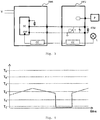
- Fig. 2 sows an example for a setup using the circuitry from Fig. 1 .
- Fig. 2 shows a diagram which exemplarily shows how the circuit according to the invention works. Like components from Fig. 1 are referenced by the same reference signs. Additionally, a power/voltage/current supply V for the operating means OM is shown, from which the integrated control circuit SE can be supplied directly or indirectly, e.g. via an rectifier. Also additionally a lighting means L is shown at which the temperature sensing means ITM senses a temperature, producing a temperature indicating signal.
- the integrated control circuit SE is shown with an additional output OUT, which is used to directly, e.g. by controlling a switch causing a dimming, e.g. for PFC, frequency or PWM dimming, or indirectly by setting a parameter in an additional circuitry component CC controlling the dimming level of lighting means L.
- Another embodiment is that the combination of the presence indicating signal and the temperature indicating signal occurs outside of the operating means OM.
- a first operating means portion OM1 basically corresponding to operating means OM
- the integrated control circuit SE again shows the output OUT as described for Fig. 2 .
- the integrated control circuit SE is again supplied directly or indirectly from a supply V as outlined for Fig. 2 .
- the integrated control circuit SE can directly or indirectly control the dimming level of the lighting means L, at which the temperature sensing means ITM senses the temperature.
- the combining circuitry combining the temperature indicating signal and the presence indicating signal is now part of a second operating means portion OM2.
- the switching element T and the capacity C are moved to the second operating means portion OM2.
- the electrical signal can be switched to the ground potential by the switching element T in the second operating means portion OM2.
- the additional circuitry component CC may either be located in the first operating means portion OM2 or second operating means portion OM2, but in case further additional circuitry components are necessary, an additional circuitry component CC may be present in the first operating means portion OM1 and the second operating means portion OM2.
- protection resistor R P could be moved to the second operating means portion OM2 by extending the connection extending from pin V DDP and by addition of additional connection points at the first operating means portion OM1 and the second operating means portion OM2. This embodiment is not shown.
- the electric signal preferably a voltage or current
- the electrical signal is indicative of the temperature at the lighting means and of a detected presence.
- a range of threshold values are defined and, depending on the relation of the electric signal evaluated/measured at the common input T S to the threshold values, the integrated control circuit SE behaves differently. In particular it controls the dimming level of lighting means L differently.
- the threshold values can be stored in the integrated control circuit SE. All threshold values define different threshold values for the electric signal.
- threshold values are be used for controlling the lighting means L.
- the control circuit e.g. determines that no temperature sensing means ITM is connected. Hence, temperature information is ignored by the integrated control circuit SE and only presence detection is performed.
- the integrated control circuit SE will shut down the lighting means L or would take the necessary measures to indirectly shut down the lighting means L. Such a value of the electrical signal would indicate a very high temperature at the lighting means L and the shutdown is hence performed to prevent damage of the lighting means.
- the integrated control circuit SE will start dimming the lighting means L in order to prevent further increase of the temperature at the lighting means L.
- the integrated control circuit SE will again dim up or increase the dimming level of the lighting means L. E.g. through the down dimming after an excess of the third threshold value T 3 it is determined that the lighting means L has cooled down enough so that the lighting means L can operated normally.
- the lighting means can be operated normally and preferably with the second predetermined dimming level of e.g. 100%.
- the integrated control circuit SE will turn on the lighting means again (again directly or indirectly) if it was shut down due to an increase of the value of the electrical signal over the fourth threshold value T 4 as mentioned above.
- the presence sensing means P activates/deactivates the switching element T.
- the electrical signal at the common input T S is pulled below the specific threshold value T C .
- the integrated control circuit SE then controls the dimming level of the lighting means L to preferably about 10% or above.
- the switching element T can be activated when the presence detection signal CF is high/low and deactivated when the presence detection signal CF is low/high.
- the presence detection signal is generated by the presence sensing means P.
- the switching element T is on/off, or vice versa, and the electrical signal at the common input T S drops to a lower value, especially a voltage value pulled below the specific threshold value T C , which is close to but not necessarily zero (Volt). This means that after the electrical signal is pulled below the specific threshold value T C , effectively the temperature sensing by the temperature sensing means is deactivated.
- the lighting means L is monitored and the dimming level thereof is controlled especially to prevent the lighting means L to become too hot, i.e. to prevent the temperature at the lighting means L to increase above a defined threshold value (T 4 ).
- the integrated control circuit SE may determine that the value of the electrical signal falls below a threshold value instead checking whether the value of the electrical signal is in excess of a threshold value as mentioned above, and vice versa.
- the temperature could still be measured in case the integrated control circuit allows sensing the electrical signal with a high enough resolution so that temperature fluctuations or changes could be detected.
- the operating means OM and the first operating means portion OM1 can in particular be or comprise a LED driving module.
- the second operating means portion OM2 can be a separate extension module to provide additional functionality to the first operating means portion OM1.
- the invention hence multiplexes the information of corridor function, i.e. the information received from the presence sensing means P, to the same integrated control circuit SE input to attain a different fade rate and dim level when compared to the fade rate and dim level according to the signal generated by the temperature sensing means ITM.
- the integrated control circuit SE may also dim the lighting means L by issuing a dimming command via a bus interface to a bus system, e.g. a DALI bus. Also, the operating means and/or the integrated control circuit SE can be connected to such a bus system.
- the integrated control circuit SE may also include at least one A/D-converter to evaluate the electrical signal and to determine a value of the electrical signal.
Landscapes
- Circuit Arrangement For Electric Light Sources In General (AREA)
Claims (2)
- System, umfassend ein Betriebsmittel OM, ein Temperaturmessmittel ITM, einen Anwesenheitssensor P und ein Beleuchtungsmittel L, dadurch gekennzeichnet, dass das OM einen integrierten Regelkreis SE, einen Schutzwiderstand Rp, einen Transistor T, einen Kondensator C, eine integrierte Schaltung CC, einen ersten Pin, einen zweiten Pin, einen dritten Pin, einen dritten Pin und einen vierten Pin umfasst, und• wobei der integrierte Regelkreis SE einen Spannungsversorgungspin VDDP, einen gemeinsamen Eingangspin Ts, einen Massepunkt GND und einen Ausgangspin aufweist,• wobei der gemeinsame Eingangspin Ts über eine erste Verbindung an den zweiten Pin angeschlossen ist und der Massepunkt GND über eine zweite Verbindung an den dritten Pin angeschlossen ist,• ein erstes Ende des Temperaturmessmittels an den zweiten Pin angeschlossen ist und ein zweites Ende des Temperaturmessmittels an den dritten Pin angeschlossen ist, und der erste Pin an den Anwesenheitssensor angeschlossen ist, wodurch das Temperaturmessmittel und der Anweisenheitssensor mit dem OM elektrisch verbunden werden,• der erste Pin auch an ein Gate des Transistors T angeschlossen ist,• ein erstes Ende des Transistors T an einer ersten Verbindungsstelle mit der ersten Verbindung verbunden ist, ein zweites Ende des Transistors T an einer zweiten Verbindungsstelle mit der zweiten Verbindung verbunden ist, damit ein vom Anweisenheitssensor P erzeugtes Anwesenheitserkennungssignal CF den in einen leitenden Zustand übergehenden Transistor macht und ein Nichtvorhandensein des Anwesenheitserkennungssignals CF den in einen Sperrzustand übergehenden Transistor macht,• ein erstes Ende des Kondensators C mit der ersten Verbindung zwischen der ersten Verbindungsstelle und dem zweiten Pin verbunden ist und ein zweites Ende des Kondensators C mit der zweiten Verbindung zwischen der zweiten Verbindungsstelle und dem dritten Pin verbunden ist, damit der Transistor und der Kondensator C in Bezug auf die erste und zweite Verbindung parallel zueinander vorgesehen sind,• ein erstes Ende des Schutzwiderstandes Rp an den Spannungsversorgungspin VDDP angeschlossen ist und ein zweites Ende des Schutzwiderstandes Rp an die erste Verbindungsleitung an einer dritten Verbindungsstelle zwischen dem gemeinsamen Eingang Ts und der ersten Verbindungsstelle angeschlossen ist,• wobei der Ausgangspin an die integrierte Schaltung angeschlossen ist und die integrierte Schaltung an den vierten Pin angeschlossen ist und der vierte Pin an das Beleuchtungsmittel L angeschlossen ist,• wobei der Anwesenheitssensor P derart konfiguriert ist, dass er erkennt, ob eine Zeitüberschreitung vorliegt, nachdem eine letzte Bewegung bzw. Anwesenheit vom Anwesenheitssensor erkannt wurde,▪ wenn der Anwesenheitssensor P die Zeitüberschreitung erkennt:∘ ist der Anwesenheitssensor P derart konfiguriert, das er infolge der Zeitüberschreitung das Erkennungssignal CF am Anwesenheitssensor P erzeugt, wodurch der in den leitenden Zustand eintretende Transistor T gemacht wird, damit ein Wert eines elektrischen Signals am gemeinsamen Eingang Ts eine erste Schwelle Tc unterschreitet,∘ ist der integrierte Regelkreis SE als Reaktion darauf, dass der Wert des elektrischen Signals am gemeinsamen Eingang Ts die erste Schwelle Tc unterschreitet, derart konfiguriert, dass er einen Parameter der integrierten Schaltung CC auf einen ersten Wert einstellt, damit die integrierte Schaltung CC derart konfiguriert ist, dass sie aufgrund des ersten Werts des Parameter seinen Dimmwert des Beleuchtungsmittels L auf einen ersten vorgegebenen Dimmwert ungleich Null einstellt, und die integrierte Schaltung CC derart konfiguriert ist, dass sie aufgrund des ersten Werts des Parameters den Dimmwert des Beleuchtungsmittels auf den ersten vorgegebenen Dimmwert einstellt,▪ ansonsten, wenn der Anwesenheitssensor P nach der Erkennung der letzten Bewegung oder Anwesenheit durch den Anwesenheitssensor keine Zeitüberschreitung erkennt:
∘ ist der Transistor T derart konfiguriert, dass er sich im Sperrzustand befindet, damit ein Wert des elektrischen Signals am gemeinsamen Eingang Ts die erste Schwelle Tc übersteigt, und der integrierte Regelkreis SE ist als Reaktion darauf, dass der Wert des elektrischen Signals am gemeinsamen Eingang Ts die erste Schwelle Tc überschreitet, derart konfiguriert, dass er den Parameter der integrierten Schaltung CC auf einen zweiten Wert einstellt, damit die IC CC derart konfiguriert wird, dass sie aufgrund des zweiten Werts den Dimmwert des Beleuchtungsmittels L auf einen zweiten vorgegebenen Dimmwert einstellt, der den ersten vorgegebenen Dimmwert übersteigt, und die integrierte Schaltung CC ist derart konfiguriert, dass sie aufgrund des zweiten Werts des Parameters den Dimmwert des Beleuchtungsmittels auf den zweiten vorgegebenen Dimmwert einstellt. - Von einem System nach Anspruch 1 ausgeführtes Verfahren, wobei das Verfahren die Schritte umfasst:• Ermitteln durch den Anwesenheitssensor P, ob eine Zeitüberschreitung vorliegt, nachdem eine letzte Bewegung bzw. Anwesenheit vom Anwesenheitssensor erkannt wurde,▪ wenn der Anwesenheitssensor P die Zeitüberschreitung erkennt:∘ Erzeugen des Erkennungssignals CF am Anwesenheitssensor P durch den Anwesenheitssensor infolge der Zeitüberschreitung, wodurch der in einen leitenden Zustand eintretende Transistor T gemacht wird, damit ein Wert eines elektrischen Signals am gemeinsamen Eingang Ts eine erste Schwelle Tc unterschreitet,∘ als Reaktion darauf, dass der Wert des elektrischen Signals am gemeinsamen Eingang Ts die erste Schwelle Tc unterschreitet, Einstellen eines Parameters in der integrierten Schaltung CC auf einen ersten Wert durch den integrierten Regelkreis SE und Einstellen des Dimmwerts des Beleuchtungsmittels auf den ersten vorgegebenen Dimmwert durch die integrierte Schaltung CC aufgrund des ersten Werts des Parameters,▪ ansonsten, wenn der Anwesenheitssensor P nach der Erkennung einer letzten Bewegung oder Anwesenheit durch den Anwesenheitssensor keine Zeitüberschreitung erkennt:
∘ Übergehen in einen Sperrzustand durch den Transistor T, damit der Wert des elektrischen Signals am gemeinsamen Eingang Ts die erste Schwelle Tc übersteigt und als Reaktion darauf, dass der Wert des elektrischen Signals am gemeinsamen Eingang Ts die erste Schwelle Tc überschreitet, Einstellen des Parameters in der integrierten Schaltung CC auf einen zweiten Wert durch den integrierten Regelkreis SE und Einstellen des Dimmwerts des Beleuchtungsmittels L auf einen zweiten vorgegebenen Dimmwert, der den ersten vorgegebenen Dimmwert übersteigt, aufgrund des zweiten Werts.
Priority Applications (3)
| Application Number | Priority Date | Filing Date | Title |
|---|---|---|---|
| EP13178352.4A EP2833701B1 (de) | 2013-07-29 | 2013-07-29 | Integrierbare Steuerschaltung mit kombinierter Temperatur- und Präsenzerkennung |
| PCT/EP2014/066022 WO2015014740A2 (en) | 2013-07-29 | 2014-07-25 | Integrated control circuit with combined temperature and presence detection |
| US14/907,361 US9750111B2 (en) | 2013-07-29 | 2014-07-25 | Integrated control circuit with combined temperature and presence detection |
Applications Claiming Priority (1)
| Application Number | Priority Date | Filing Date | Title |
|---|---|---|---|
| EP13178352.4A EP2833701B1 (de) | 2013-07-29 | 2013-07-29 | Integrierbare Steuerschaltung mit kombinierter Temperatur- und Präsenzerkennung |
Publications (2)
| Publication Number | Publication Date |
|---|---|
| EP2833701A1 EP2833701A1 (de) | 2015-02-04 |
| EP2833701B1 true EP2833701B1 (de) | 2020-01-22 |
Family
ID=48874922
Family Applications (1)
| Application Number | Title | Priority Date | Filing Date |
|---|---|---|---|
| EP13178352.4A Active EP2833701B1 (de) | 2013-07-29 | 2013-07-29 | Integrierbare Steuerschaltung mit kombinierter Temperatur- und Präsenzerkennung |
Country Status (3)
| Country | Link |
|---|---|
| US (1) | US9750111B2 (de) |
| EP (1) | EP2833701B1 (de) |
| WO (1) | WO2015014740A2 (de) |
Family Cites Families (6)
| Publication number | Priority date | Publication date | Assignee | Title |
|---|---|---|---|---|
| US6798341B1 (en) * | 1998-05-18 | 2004-09-28 | Leviton Manufacturing Co., Inc. | Network based multiple sensor and control device with temperature sensing and control |
| US9013059B2 (en) * | 2009-07-30 | 2015-04-21 | Lutron Electronics Co., Inc. | Load control system having an energy savings mode |
| DE102011114882A1 (de) * | 2010-10-15 | 2012-04-19 | Ceramtec Gmbh | LED-Leuchte mit integriertem Treiber |
| CA2816978C (en) * | 2010-11-04 | 2020-07-28 | Digital Lumens Incorporated | Method, apparatus, and system for occupancy sensing |
| US20130063032A1 (en) * | 2011-09-12 | 2013-03-14 | Full Spectrum Solutions | Induction lamp connected light node |
| US8755039B2 (en) * | 2012-05-03 | 2014-06-17 | Abl Ip Holding Llc | Lighting devices with sensors for detecting one or more external conditions and networked system using such devices |
-
2013
- 2013-07-29 EP EP13178352.4A patent/EP2833701B1/de active Active
-
2014
- 2014-07-25 WO PCT/EP2014/066022 patent/WO2015014740A2/en not_active Ceased
- 2014-07-25 US US14/907,361 patent/US9750111B2/en not_active Expired - Fee Related
Non-Patent Citations (1)
| Title |
|---|
| None * |
Also Published As
| Publication number | Publication date |
|---|---|
| US20160174338A1 (en) | 2016-06-16 |
| WO2015014740A3 (en) | 2015-04-30 |
| US9750111B2 (en) | 2017-08-29 |
| WO2015014740A2 (en) | 2015-02-05 |
| EP2833701A1 (de) | 2015-02-04 |
Similar Documents
| Publication | Publication Date | Title |
|---|---|---|
| US8773032B2 (en) | LED light source with multiple independent control inputs and interoperability | |
| KR101201803B1 (ko) | 점등스위치형 디밍제어모듈을 이용한 엘이디 조명 디밍 제어장치 | |
| TWI511610B (zh) | 發光二極體驅動裝置及發光二極體驅動方法 | |
| EP3595411B1 (de) | Dimmerschaltung für led-lampe | |
| KR102051694B1 (ko) | 누설 전류 검출 회로, 이를 포함하는 조명 장치 및 누설 전류 검출 방법 | |
| EP3716734B1 (de) | Steuerschaltung für einen phasenschnittdimmer | |
| KR102069006B1 (ko) | 셀프 디밍 유기 발광 다이오드 조명 시스템 및 제어 방법 | |
| WO2008086050B1 (en) | Electronic circuit for driving a diode load | |
| KR20130015714A (ko) | 백라이트 유닛 및 led 제어방법 | |
| CN103889104B (zh) | 发光二极管驱动电路及其保护方法 | |
| CN107637179B (zh) | 照明系统 | |
| JP2010530608A (ja) | 電球タイプに基づく調光アルゴリズム | |
| KR20150013314A (ko) | 전기적 부하를 제어하기 위한 방법, 장치 및 시스템 | |
| US9538592B2 (en) | LED lighting system | |
| JP5812292B2 (ja) | 標識灯および標識灯システム | |
| US20140132273A1 (en) | Light-emitting element failure detector and method for detecting light-emitting element failure | |
| KR20130017024A (ko) | Led 발광 장치 및 그 구동 방법 | |
| CN102316629B (zh) | 直流电源装置及led照明装置 | |
| KR20120087132A (ko) | 대형 고체상태 led용 전자 드라이버 장치 및 전력 공급 방법 | |
| EP2833701B1 (de) | Integrierbare Steuerschaltung mit kombinierter Temperatur- und Präsenzerkennung | |
| EP2127080B1 (de) | Stromversorgungsschaltvorrichtung mit starküberlastungsdetektion | |
| CN101822126A (zh) | 将发光器件操作机构调光至预定电平 | |
| JP2019121445A (ja) | ショート判定装置、及び、光照射装置 | |
| EP2950620B1 (de) | Universeller digitaler dimmer | |
| KR101512727B1 (ko) | 발광다이오드 구동 회로 |
Legal Events
| Date | Code | Title | Description |
|---|---|---|---|
| 17P | Request for examination filed |
Effective date: 20130729 |
|
| AK | Designated contracting states |
Kind code of ref document: A1 Designated state(s): AL AT BE BG CH CY CZ DE DK EE ES FI FR GB GR HR HU IE IS IT LI LT LU LV MC MK MT NL NO PL PT RO RS SE SI SK SM TR |
|
| AX | Request for extension of the european patent |
Extension state: BA ME |
|
| PUAI | Public reference made under article 153(3) epc to a published international application that has entered the european phase |
Free format text: ORIGINAL CODE: 0009012 |
|
| R17P | Request for examination filed (corrected) |
Effective date: 20150723 |
|
| RBV | Designated contracting states (corrected) |
Designated state(s): AL AT BE BG CH CY CZ DE DK EE ES FI FR GB GR HR HU IE IS IT LI LT LU LV MC MK MT NL NO PL PT RO RS SE SI SK SM TR |
|
| STAA | Information on the status of an ep patent application or granted ep patent |
Free format text: STATUS: EXAMINATION IS IN PROGRESS |
|
| 17Q | First examination report despatched |
Effective date: 20170120 |
|
| GRAP | Despatch of communication of intention to grant a patent |
Free format text: ORIGINAL CODE: EPIDOSNIGR1 |
|
| STAA | Information on the status of an ep patent application or granted ep patent |
Free format text: STATUS: GRANT OF PATENT IS INTENDED |
|
| INTG | Intention to grant announced |
Effective date: 20191024 |
|
| RIN1 | Information on inventor provided before grant (corrected) |
Inventor name: DALBY, PAUL Inventor name: FRANKLAND, JAMES Inventor name: JAGJITPATI, SHUKLA Inventor name: WILSON, IAN |
|
| GRAS | Grant fee paid |
Free format text: ORIGINAL CODE: EPIDOSNIGR3 |
|
| GRAA | (expected) grant |
Free format text: ORIGINAL CODE: 0009210 |
|
| STAA | Information on the status of an ep patent application or granted ep patent |
Free format text: STATUS: THE PATENT HAS BEEN GRANTED |
|
| AK | Designated contracting states |
Kind code of ref document: B1 Designated state(s): AL AT BE BG CH CY CZ DE DK EE ES FI FR GB GR HR HU IE IS IT LI LT LU LV MC MK MT NL NO PL PT RO RS SE SI SK SM TR |
|
| REG | Reference to a national code |
Ref country code: GB Ref legal event code: FG4D |
|
| REG | Reference to a national code |
Ref country code: CH Ref legal event code: EP |
|
| REG | Reference to a national code |
Ref country code: DE Ref legal event code: R096 Ref document number: 602013065243 Country of ref document: DE |
|
| REG | Reference to a national code |
Ref country code: AT Ref legal event code: REF Ref document number: 1227794 Country of ref document: AT Kind code of ref document: T Effective date: 20200215 |
|
| REG | Reference to a national code |
Ref country code: IE Ref legal event code: FG4D |
|
| REG | Reference to a national code |
Ref country code: DE Ref legal event code: R084 Ref document number: 602013065243 Country of ref document: DE |
|
| REG | Reference to a national code |
Ref country code: NL Ref legal event code: MP Effective date: 20200122 |
|
| REG | Reference to a national code |
Ref country code: LT Ref legal event code: MG4D |
|
| PG25 | Lapsed in a contracting state [announced via postgrant information from national office to epo] |
Ref country code: RS Free format text: LAPSE BECAUSE OF FAILURE TO SUBMIT A TRANSLATION OF THE DESCRIPTION OR TO PAY THE FEE WITHIN THE PRESCRIBED TIME-LIMIT Effective date: 20200122 Ref country code: FI Free format text: LAPSE BECAUSE OF FAILURE TO SUBMIT A TRANSLATION OF THE DESCRIPTION OR TO PAY THE FEE WITHIN THE PRESCRIBED TIME-LIMIT Effective date: 20200122 Ref country code: NO Free format text: LAPSE BECAUSE OF FAILURE TO SUBMIT A TRANSLATION OF THE DESCRIPTION OR TO PAY THE FEE WITHIN THE PRESCRIBED TIME-LIMIT Effective date: 20200422 Ref country code: PT Free format text: LAPSE BECAUSE OF FAILURE TO SUBMIT A TRANSLATION OF THE DESCRIPTION OR TO PAY THE FEE WITHIN THE PRESCRIBED TIME-LIMIT Effective date: 20200614 Ref country code: NL Free format text: LAPSE BECAUSE OF FAILURE TO SUBMIT A TRANSLATION OF THE DESCRIPTION OR TO PAY THE FEE WITHIN THE PRESCRIBED TIME-LIMIT Effective date: 20200122 |
|
| PG25 | Lapsed in a contracting state [announced via postgrant information from national office to epo] |
Ref country code: HR Free format text: LAPSE BECAUSE OF FAILURE TO SUBMIT A TRANSLATION OF THE DESCRIPTION OR TO PAY THE FEE WITHIN THE PRESCRIBED TIME-LIMIT Effective date: 20200122 Ref country code: GR Free format text: LAPSE BECAUSE OF FAILURE TO SUBMIT A TRANSLATION OF THE DESCRIPTION OR TO PAY THE FEE WITHIN THE PRESCRIBED TIME-LIMIT Effective date: 20200423 Ref country code: LV Free format text: LAPSE BECAUSE OF FAILURE TO SUBMIT A TRANSLATION OF THE DESCRIPTION OR TO PAY THE FEE WITHIN THE PRESCRIBED TIME-LIMIT Effective date: 20200122 Ref country code: IS Free format text: LAPSE BECAUSE OF FAILURE TO SUBMIT A TRANSLATION OF THE DESCRIPTION OR TO PAY THE FEE WITHIN THE PRESCRIBED TIME-LIMIT Effective date: 20200522 Ref country code: SE Free format text: LAPSE BECAUSE OF FAILURE TO SUBMIT A TRANSLATION OF THE DESCRIPTION OR TO PAY THE FEE WITHIN THE PRESCRIBED TIME-LIMIT Effective date: 20200122 Ref country code: BG Free format text: LAPSE BECAUSE OF FAILURE TO SUBMIT A TRANSLATION OF THE DESCRIPTION OR TO PAY THE FEE WITHIN THE PRESCRIBED TIME-LIMIT Effective date: 20200422 |
|
| REG | Reference to a national code |
Ref country code: DE Ref legal event code: R097 Ref document number: 602013065243 Country of ref document: DE |
|
| PG25 | Lapsed in a contracting state [announced via postgrant information from national office to epo] |
Ref country code: CZ Free format text: LAPSE BECAUSE OF FAILURE TO SUBMIT A TRANSLATION OF THE DESCRIPTION OR TO PAY THE FEE WITHIN THE PRESCRIBED TIME-LIMIT Effective date: 20200122 Ref country code: SK Free format text: LAPSE BECAUSE OF FAILURE TO SUBMIT A TRANSLATION OF THE DESCRIPTION OR TO PAY THE FEE WITHIN THE PRESCRIBED TIME-LIMIT Effective date: 20200122 Ref country code: RO Free format text: LAPSE BECAUSE OF FAILURE TO SUBMIT A TRANSLATION OF THE DESCRIPTION OR TO PAY THE FEE WITHIN THE PRESCRIBED TIME-LIMIT Effective date: 20200122 Ref country code: ES Free format text: LAPSE BECAUSE OF FAILURE TO SUBMIT A TRANSLATION OF THE DESCRIPTION OR TO PAY THE FEE WITHIN THE PRESCRIBED TIME-LIMIT Effective date: 20200122 Ref country code: DK Free format text: LAPSE BECAUSE OF FAILURE TO SUBMIT A TRANSLATION OF THE DESCRIPTION OR TO PAY THE FEE WITHIN THE PRESCRIBED TIME-LIMIT Effective date: 20200122 Ref country code: LT Free format text: LAPSE BECAUSE OF FAILURE TO SUBMIT A TRANSLATION OF THE DESCRIPTION OR TO PAY THE FEE WITHIN THE PRESCRIBED TIME-LIMIT Effective date: 20200122 Ref country code: EE Free format text: LAPSE BECAUSE OF FAILURE TO SUBMIT A TRANSLATION OF THE DESCRIPTION OR TO PAY THE FEE WITHIN THE PRESCRIBED TIME-LIMIT Effective date: 20200122 Ref country code: SM Free format text: LAPSE BECAUSE OF FAILURE TO SUBMIT A TRANSLATION OF THE DESCRIPTION OR TO PAY THE FEE WITHIN THE PRESCRIBED TIME-LIMIT Effective date: 20200122 |
|
| REG | Reference to a national code |
Ref country code: AT Ref legal event code: MK05 Ref document number: 1227794 Country of ref document: AT Kind code of ref document: T Effective date: 20200122 |
|
| PLBE | No opposition filed within time limit |
Free format text: ORIGINAL CODE: 0009261 |
|
| STAA | Information on the status of an ep patent application or granted ep patent |
Free format text: STATUS: NO OPPOSITION FILED WITHIN TIME LIMIT |
|
| 26N | No opposition filed |
Effective date: 20201023 |
|
| PG25 | Lapsed in a contracting state [announced via postgrant information from national office to epo] |
Ref country code: IT Free format text: LAPSE BECAUSE OF FAILURE TO SUBMIT A TRANSLATION OF THE DESCRIPTION OR TO PAY THE FEE WITHIN THE PRESCRIBED TIME-LIMIT Effective date: 20200122 Ref country code: AT Free format text: LAPSE BECAUSE OF FAILURE TO SUBMIT A TRANSLATION OF THE DESCRIPTION OR TO PAY THE FEE WITHIN THE PRESCRIBED TIME-LIMIT Effective date: 20200122 |
|
| PG25 | Lapsed in a contracting state [announced via postgrant information from national office to epo] |
Ref country code: SI Free format text: LAPSE BECAUSE OF FAILURE TO SUBMIT A TRANSLATION OF THE DESCRIPTION OR TO PAY THE FEE WITHIN THE PRESCRIBED TIME-LIMIT Effective date: 20200122 Ref country code: PL Free format text: LAPSE BECAUSE OF FAILURE TO SUBMIT A TRANSLATION OF THE DESCRIPTION OR TO PAY THE FEE WITHIN THE PRESCRIBED TIME-LIMIT Effective date: 20200122 Ref country code: MC Free format text: LAPSE BECAUSE OF FAILURE TO SUBMIT A TRANSLATION OF THE DESCRIPTION OR TO PAY THE FEE WITHIN THE PRESCRIBED TIME-LIMIT Effective date: 20200122 |
|
| REG | Reference to a national code |
Ref country code: CH Ref legal event code: PL |
|
| REG | Reference to a national code |
Ref country code: BE Ref legal event code: MM Effective date: 20200731 |
|
| PG25 | Lapsed in a contracting state [announced via postgrant information from national office to epo] |
Ref country code: LI Free format text: LAPSE BECAUSE OF NON-PAYMENT OF DUE FEES Effective date: 20200731 Ref country code: CH Free format text: LAPSE BECAUSE OF NON-PAYMENT OF DUE FEES Effective date: 20200731 Ref country code: LU Free format text: LAPSE BECAUSE OF NON-PAYMENT OF DUE FEES Effective date: 20200729 |
|
| PG25 | Lapsed in a contracting state [announced via postgrant information from national office to epo] |
Ref country code: BE Free format text: LAPSE BECAUSE OF NON-PAYMENT OF DUE FEES Effective date: 20200731 |
|
| PG25 | Lapsed in a contracting state [announced via postgrant information from national office to epo] |
Ref country code: IE Free format text: LAPSE BECAUSE OF NON-PAYMENT OF DUE FEES Effective date: 20200729 |
|
| PG25 | Lapsed in a contracting state [announced via postgrant information from national office to epo] |
Ref country code: TR Free format text: LAPSE BECAUSE OF FAILURE TO SUBMIT A TRANSLATION OF THE DESCRIPTION OR TO PAY THE FEE WITHIN THE PRESCRIBED TIME-LIMIT Effective date: 20200122 Ref country code: MT Free format text: LAPSE BECAUSE OF FAILURE TO SUBMIT A TRANSLATION OF THE DESCRIPTION OR TO PAY THE FEE WITHIN THE PRESCRIBED TIME-LIMIT Effective date: 20200122 Ref country code: CY Free format text: LAPSE BECAUSE OF FAILURE TO SUBMIT A TRANSLATION OF THE DESCRIPTION OR TO PAY THE FEE WITHIN THE PRESCRIBED TIME-LIMIT Effective date: 20200122 |
|
| PG25 | Lapsed in a contracting state [announced via postgrant information from national office to epo] |
Ref country code: MK Free format text: LAPSE BECAUSE OF FAILURE TO SUBMIT A TRANSLATION OF THE DESCRIPTION OR TO PAY THE FEE WITHIN THE PRESCRIBED TIME-LIMIT Effective date: 20200122 Ref country code: AL Free format text: LAPSE BECAUSE OF FAILURE TO SUBMIT A TRANSLATION OF THE DESCRIPTION OR TO PAY THE FEE WITHIN THE PRESCRIBED TIME-LIMIT Effective date: 20200122 |
|
| P01 | Opt-out of the competence of the unified patent court (upc) registered |
Effective date: 20230530 |
|
| PGFP | Annual fee paid to national office [announced via postgrant information from national office to epo] |
Ref country code: FR Payment date: 20230725 Year of fee payment: 11 |
|
| PGFP | Annual fee paid to national office [announced via postgrant information from national office to epo] |
Ref country code: DE Payment date: 20240730 Year of fee payment: 12 |
|
| PGFP | Annual fee paid to national office [announced via postgrant information from national office to epo] |
Ref country code: GB Payment date: 20240724 Year of fee payment: 12 |
|
| PG25 | Lapsed in a contracting state [announced via postgrant information from national office to epo] |
Ref country code: FR Free format text: LAPSE BECAUSE OF NON-PAYMENT OF DUE FEES Effective date: 20240731 |
|
| REG | Reference to a national code |
Ref country code: DE Ref legal event code: R119 Ref document number: 602013065243 Country of ref document: DE |
|
| GBPC | Gb: european patent ceased through non-payment of renewal fee |
Effective date: 20250729 |
|
| PG25 | Lapsed in a contracting state [announced via postgrant information from national office to epo] |
Ref country code: GB Free format text: LAPSE BECAUSE OF NON-PAYMENT OF DUE FEES Effective date: 20250729 |
|
| PG25 | Lapsed in a contracting state [announced via postgrant information from national office to epo] |
Ref country code: DE Free format text: LAPSE BECAUSE OF NON-PAYMENT OF DUE FEES Effective date: 20260203 |