EP2833648B1 - Electrodynamic loudspeaker with conducting elements - Google Patents
Electrodynamic loudspeaker with conducting elements Download PDFInfo
- Publication number
- EP2833648B1 EP2833648B1 EP14179579.9A EP14179579A EP2833648B1 EP 2833648 B1 EP2833648 B1 EP 2833648B1 EP 14179579 A EP14179579 A EP 14179579A EP 2833648 B1 EP2833648 B1 EP 2833648B1
- Authority
- EP
- European Patent Office
- Prior art keywords
- loudspeaker
- ring
- voice coil
- magnet
- pole piece
- Prior art date
- Legal status (The legal status is an assumption and is not a legal conclusion. Google has not performed a legal analysis and makes no representation as to the accuracy of the status listed.)
- Active
Links
- 230000005520 electrodynamics Effects 0.000 title description 8
- RYGMFSIKBFXOCR-UHFFFAOYSA-N Copper Chemical compound [Cu] RYGMFSIKBFXOCR-UHFFFAOYSA-N 0.000 claims description 39
- 230000005291 magnetic effect Effects 0.000 claims description 35
- XAGFODPZIPBFFR-UHFFFAOYSA-N aluminium Chemical compound [Al] XAGFODPZIPBFFR-UHFFFAOYSA-N 0.000 claims description 31
- 229910052782 aluminium Inorganic materials 0.000 claims description 31
- 229910052802 copper Inorganic materials 0.000 claims description 20
- 239000010949 copper Substances 0.000 claims description 20
- 238000006073 displacement reaction Methods 0.000 description 24
- AZDRQVAHHNSJOQ-UHFFFAOYSA-N alumane Chemical group [AlH3] AZDRQVAHHNSJOQ-UHFFFAOYSA-N 0.000 description 18
- 230000004907 flux Effects 0.000 description 14
- 230000007423 decrease Effects 0.000 description 11
- 230000001419 dependent effect Effects 0.000 description 11
- 238000000034 method Methods 0.000 description 7
- 229910000831 Steel Inorganic materials 0.000 description 4
- 239000010959 steel Substances 0.000 description 4
- 238000013459 approach Methods 0.000 description 3
- 239000004020 conductor Substances 0.000 description 3
- 241000239290 Araneae Species 0.000 description 2
- 229910052779 Neodymium Inorganic materials 0.000 description 2
- 239000000428 dust Substances 0.000 description 2
- 230000000694 effects Effects 0.000 description 2
- 230000006872 improvement Effects 0.000 description 2
- 230000001939 inductive effect Effects 0.000 description 2
- QEFYFXOXNSNQGX-UHFFFAOYSA-N neodymium atom Chemical compound [Nd] QEFYFXOXNSNQGX-UHFFFAOYSA-N 0.000 description 2
- 238000004804 winding Methods 0.000 description 2
- 229910000828 alnico Inorganic materials 0.000 description 1
- 230000008901 benefit Effects 0.000 description 1
- POIUWJQBRNEFGX-XAMSXPGMSA-N cathelicidin Chemical compound C([C@@H](C(=O)N[C@@H](CCCNC(N)=N)C(=O)N[C@@H](CCCCN)C(=O)N[C@@H](CO)C(=O)N[C@@H](CCCCN)C(=O)N[C@@H](CCC(O)=O)C(=O)N[C@@H](CCCCN)C(=O)N[C@@H]([C@@H](C)CC)C(=O)NCC(=O)N[C@@H](CCCCN)C(=O)N[C@@H](CCC(O)=O)C(=O)N[C@@H](CC=1C=CC=CC=1)C(=O)N[C@@H](CCCCN)C(=O)N[C@@H](CCCNC(N)=N)C(=O)N[C@@H]([C@@H](C)CC)C(=O)N[C@@H](C(C)C)C(=O)N[C@@H](CCC(N)=O)C(=O)N[C@@H](CCCNC(N)=N)C(=O)N[C@@H]([C@@H](C)CC)C(=O)N[C@@H](CCCCN)C(=O)N[C@@H](CC(O)=O)C(=O)N[C@@H](CC=1C=CC=CC=1)C(=O)N[C@@H](CC(C)C)C(=O)N[C@@H](CCCNC(N)=N)C(=O)N[C@@H](CC(N)=O)C(=O)N[C@@H](CC(C)C)C(=O)N[C@@H](C(C)C)C(=O)N1[C@@H](CCC1)C(=O)N[C@@H](CCCNC(N)=N)C(=O)N[C@@H]([C@@H](C)O)C(=O)N[C@@H](CCC(O)=O)C(=O)N[C@@H](CO)C(O)=O)NC(=O)[C@H](CC=1C=CC=CC=1)NC(=O)[C@H](CC(O)=O)NC(=O)CNC(=O)[C@H](CC(C)C)NC(=O)[C@@H](N)CC(C)C)C1=CC=CC=C1 POIUWJQBRNEFGX-XAMSXPGMSA-N 0.000 description 1
- 238000005094 computer simulation Methods 0.000 description 1
- 230000001627 detrimental effect Effects 0.000 description 1
- 230000005294 ferromagnetic effect Effects 0.000 description 1
- 239000003302 ferromagnetic material Substances 0.000 description 1
- 230000006698 induction Effects 0.000 description 1
- 230000003993 interaction Effects 0.000 description 1
- 238000012886 linear function Methods 0.000 description 1
- 239000000463 material Substances 0.000 description 1
- 238000005259 measurement Methods 0.000 description 1
- 230000002093 peripheral effect Effects 0.000 description 1
- 230000035699 permeability Effects 0.000 description 1
- 238000007747 plating Methods 0.000 description 1
- 229920006395 saturated elastomer Polymers 0.000 description 1
- 238000004088 simulation Methods 0.000 description 1
- 230000005236 sound signal Effects 0.000 description 1
- 239000000725 suspension Substances 0.000 description 1
- 229910000859 α-Fe Inorganic materials 0.000 description 1
Images


Classifications
-
- H—ELECTRICITY
- H04—ELECTRIC COMMUNICATION TECHNIQUE
- H04R—LOUDSPEAKERS, MICROPHONES, GRAMOPHONE PICK-UPS OR LIKE ACOUSTIC ELECTROMECHANICAL TRANSDUCERS; DEAF-AID SETS; PUBLIC ADDRESS SYSTEMS
- H04R9/00—Transducers of moving-coil, moving-strip, or moving-wire type
- H04R9/02—Details
-
- H—ELECTRICITY
- H04—ELECTRIC COMMUNICATION TECHNIQUE
- H04R—LOUDSPEAKERS, MICROPHONES, GRAMOPHONE PICK-UPS OR LIKE ACOUSTIC ELECTROMECHANICAL TRANSDUCERS; DEAF-AID SETS; PUBLIC ADDRESS SYSTEMS
- H04R9/00—Transducers of moving-coil, moving-strip, or moving-wire type
- H04R9/02—Details
- H04R9/025—Magnetic circuit
-
- H—ELECTRICITY
- H04—ELECTRIC COMMUNICATION TECHNIQUE
- H04R—LOUDSPEAKERS, MICROPHONES, GRAMOPHONE PICK-UPS OR LIKE ACOUSTIC ELECTROMECHANICAL TRANSDUCERS; DEAF-AID SETS; PUBLIC ADDRESS SYSTEMS
- H04R2209/00—Details of transducers of the moving-coil, moving-strip, or moving-wire type covered by H04R9/00 but not provided for in any of its subgroups
- H04R2209/022—Aspects regarding the stray flux internal or external to the magnetic circuit, e.g. shielding, shape of magnetic circuit, flux compensation coils
Definitions
- Embodiments relate to electrodynamic loudspeakers having conducting elements.
- An electrodynamic motor includes a magnet assembly that generates a constant magnetic field in a magnetic air gap and the voice coil immersed in the gap.
- the alternating current actuates the voice coil to move back and forth in the magnetic air gap and, correspondingly, move the diaphragm to which the coil (or coil former) is attached.
- the reciprocating voice coil actuates the diaphragm to likewise reciprocate and, consequently, produce acoustic signals that propagate as sound waves through air.
- the product Bl (called the force factor) is a function of the voice coil position in the voice coil gap: Bl ( x ), as shown in Figure 1 .
- the typical dependence of the Bl -product on displacement is essentially that of a soft limiter and remains almost constant at low levels of signal, thus producing minimum nonlinear distortion.
- the voice coil inductance is a function of the voice coil's position and it also depends on the instantaneous value of the current: L vc ( x , i ), as shown in Figures 2 and 3 , respectively, even at very small levels of signal.
- the voice coil When the voice coil is in the inward position, it is surrounded by steel parts of the motor and its inductance is higher compared to the outward protruding position when part of the voice coil is surrounded by air.
- the high-level current runs through the voice coil, it may saturate parts of the steel adjacent to the voice coil. Saturated steel has lower magnetic permeability and therefore the voice coil inductance decreases.
- One method to minimize variation of the alternating magnetic flux produced by the voice coil, and correspondingly, to minimize the voice coil inductance value at a zero position, as well as to minimize the dependence of the voice coil inductance on the coil's position and current involves implementing a selected conducting element.
- conductive plating may be provided on a pole piece, a conductive cap may be provided over the pole piece, and a conductive ring may be used ( Gander M, J. Audio Eng. Soc., vol. 29, pp. 10-26, 1981, Jan./Feb ).
- the conductive elements act as a single-turn secondary winding of a transformer.
- the alternating current generated in the "secondary" turn produces an alternating current.
- This current generates an alternating magnetic flux opposite in sign to the flux generated by the voice coil and therefore decreases it.
- Such methods may be directed to minimizing the voice coil dependence on current and may decrease the absolute value of the inductance. However, they may not improve linearity of the voice coil inductance as a function of displacement.
- the nonlinearity that distorts a signal at its low levels is especially detrimental to the audible sound quality. Therefore, it is important to keep the "linear" value of the voice coil inductance as well as its variation on displacement and current low to minimize the flux modulation and to decrease the high-frequency attenuation cause by the impedance's inductive component.
- a loudspeaker includes a motor assembly including a disk or annular magnet having a first face and a second face, a back plate abutting the magnet first face, a pole piece centrally disposed with respect to the back plate and extending upwardly beyond the magnet second face, and a top plate concentrically disposed with respect to the pole piece abutting one of the magnet or the back plate and extending upwardly beyond the magnet second face.
- a non-magnetic electrically conducting frame is attached to the top plate, a non-magnetic electrically conducting cap is disposed within the motor assembly and encircling the pole piece, a first non-magnetic electrically conducting ring is disposed within the top plate or the pole piece and encircling the pole piece, and at least one second non-magnetic electrically conducting ring is disposed within the motor assembly and abutting the back plate.
- a loudspeaker in another embodiment, includes a motor assembly including a magnet having a first face and a second face, a back plate abutting the magnet first face, a pole piece abutting the magnet second face, and a top plate concentrically disposed with respect to the pole piece and abutting the back plate.
- a frame is attached to the top plate and at least partially formed of aluminum, a copper cap is disposed within the motor assembly and encircling the pole piece, a copper ring is disposed within the motor assembly and encircling the pole piece, and at least one aluminum ring is disposed within the motor assembly and abutting the back plate.
- a loudspeaker in another embodiment, includes a motor assembly including a back plate, a pole piece centrally mounted on the back plate, a top plate concentrically disposed about the pole piece, and a magnet concentrically disposed about the pole piece between the back plate and the top plate.
- a frame is attached to the top plate and at least partially formed from aluminum, a copper cap is disposed within the motor assembly and encircling the pole piece, a copper ring is disposed within the motor assembly and encircling the pole piece, and at least one aluminum ring is disposed within the motor assembly and abutting the back plate.
- Various embodiments as disclosed herein include a plurality of conductive elements in the voice coil gap and around its vicinity to linearize the force factor Bl as a function of the voice coil position Bl ( x ), and the voice coil inductance L vc as a function of the coil's position L vc ( x ) and the function of the voice coil's current L vc ( i ).
- the absolute value of the voice coil's inductance L vc is very low.
- FIG 4 is a cross-sectional view of a loudspeaker 10 having an internal magnet and a plurality of conducting elements.
- Loudspeaker 10 generally comprises a frame 12, a motor assembly 14, a voice coil and former 16, and a cone (or diaphragm) and dust cap 18.
- the loudspeaker 10 may also include other components, such as a spider (not shown), as is known in the art.
- the motor assembly 14 includes a permanent magnet 20, such as a neodymium internal magnet, where the magnet 20 has a first face 22 and a second face 24.
- the motor assembly 14 further includes a back plate 26 abutting the magnet first face 22, and a pole piece 28 centrally disposed with respect to the back plate 26, abutting the magnet second face 24 and extending beyond the magnet second face 24.
- a top plate 30 is concentrically disposed with respect to the pole piece 28, abutting the back plate 26 and extending beyond the magnet second face 24.
- the back plate 26 could also be defined as a shellpot structure with a pot wall attached to the back plate and a magnet received in the shellpot.
- a magnetic gap 31 is formed between the pole piece 28 and top plate 30 within which the voice coil 16 is axially movable.
- the frame 12 is constructed from a non-magnetic conducting material, wherein in one embodiment at least a portion of the frame 12 comprises aluminum, or may alternatively comprise copper.
- the lower part of the frame 12 adjacent to the voice coil 16 behaves similar to a shorting ring, and the frame 12 provides linearization and symmetry of the alternating flux and, correspondingly, the voice coil's inductance.
- the top plate 30 may include a groove 32 formed along an inner surface 33 thereof which linearizes the force factor Bl(x) and can receive a first non-magnetic conducting ring 34.
- the first ring 34 comprises copper. Any dimensions and geometry of the first ring 34 appropriate for a particular loudspeaker may be utilized.
- Figure 6 illustrates an alternative position of the first ring 34 disposed within the pole piece 28. In both the embodiments of Figure 4 and Figure 6 , the first ring 34 is disposed within the motor assembly 14 so as to encircle the pole piece 28.
- the loudspeaker 10 may include a non-magnetic conducting cap 36 disposed within the motor assembly 14 and encircling the pole piece 28.
- the cap 36 comprises copper.
- the cap 36 may abut two adjacent surfaces within the motor assembly 14 and may have a thickness of approximately 0.01 inches.
- any dimensions and geometry of the cap 36 appropriate for a particular loudspeaker may be utilized.
- the cap 36 abuts a portion of the pole piece 28, covering the surface of the pole piece 28 adjacent to the voice coil gap 31.
- the cap 36 instead abuts a portion of the top plate 30.
- At least one second non-magnetic conducting ring 38 may be disposed within the motor assembly 14 abutting the back plate 26.
- the second ring 38 may comprise aluminum and, as for the other conducting elements described above, can have any dimensions and geometry suitable for a particular loudspeaker implementation.
- the second ring 38 is positioned to be spaced from the magnet 20.
- Figure 5 illustrates an alternative position of the second ring 38 abutting the magnet 20.
- FIG 8 is a cross-sectional view of a loudspeaker 110 having an external magnet and a plurality of conducting elements, wherein features of loudspeaker 110 similar to loudspeaker 10 are identified with like reference numerals with the addition of a "1" prefix.
- loudspeaker 110 generally comprises a frame 112, a motor assembly 114, a voice coil and former 116, and a cone (or diaphragm) and dust cap 118.
- the loudspeaker 110 may also include other components, such as a spider (not shown), as is known in the art.
- the motor assembly 114 includes a permanent magnet 120, such as a ferrite, neodymium, or Alnico external magnet, where the magnet 120 has a first face 122 and a second face 124.
- the motor assembly 114 further includes a back plate 126 abutting the magnet first face 122, and a pole piece 128 centrally mounted with respect to the back plate 126 extending beyond the magnet second face 124.
- a top plate 130 is concentrically disposed with respect to the pole piece 128 and extending beyond the magnet second face 124.
- the magnet 120 is concentrically disposed about the pole piece 128 between the back plate 126 and the top plate 130.
- a magnetic gap is formed between the pole piece 128 and top plate 130 within which the voice coil 116 is axially movable.
- Figure 8 illustrates a loudspeaker 110 having the conducting elements described above, namely the frame 112, first ring 134, cap 136 and second ring 138, where it is understood that any of the conducting elements can have alternate positioning as described with reference to loudspeaker 10.
- Figures 9 and 10 depict further alternatives for conducting elements with reference to loudspeaker 110, although these alternatives are equally applicable to the embodiment of loudspeaker 10.
- FIG. 10 illustrates an embodiment of loudspeaker 110 which includes a third non-magnetic conducting ring 140, which may comprise aluminum, abutting a top surface 142 of the pole piece 128.
- loudspeaker embodiments are not limited to those depicted herein, and that the placement of conducting elements within any embodiment can be interchanged and combined to form other embodiments.
- the overall result is the increased linearity of the force Bl ( x ) i driving the voice coil 16 and minimization of the constant magnetic flux modulation due to the small value and linearity of the voice coil inductance L vc ( x , i ).
- This provides minimization of the corresponding nonlinear voltage term: d L vc ( x , i )/d x d i as well as the nonlinear force term responsible for the reluctance force: 0.5 ⁇ (d L vc ( x , i )/d x ) ⁇ i 2 (see equations 1 and 2).
- Each conducting element contributes to the decrease of inductance and resistive losses associated with alternating magnetic flux.
- the aluminum ring 38 may not decrease the resistive losses at rest position since the copper elements 34, 36 are dominant, but it improves the linearity and symmetry.
- the low zero-displacement level of the voice coil inductance L vc ( x ) is provided by alternating magnetic fluxes generated by the combination of the copper cap 36 and the copper ring 34. Symmetry of the inductance L vc ( x ) is provided by the balance between the alternating flux generated by the lower part of the frame 12 and the alternating flux generated by the aluminum ring 38.
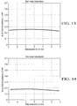
- Figures 11-14 are graphs of the measured voice coil inductance as a function of displacement for a loudspeaker embodiment with an aluminum frame as a conducting element ( Fig. 11 ), a loudspeaker embodiment with an aluminum frame and copper ring as conducting elements ( Fig. 12 ), a loudspeaker embodiment with an aluminum frame, a copper ring, and an aluminum ring as conducting elements ( Fig. 13 ), and a loudspeaker embodiment with an aluminum frame, a copper ring, an aluminum ring and a copper cap as conducting elements ( Fig. 14 ).
- Significant linearization of the voice coil inductance is observed with the addition of conducting elements.
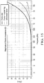
- the reduced inductance also has significant influence on the electrical impedance of the voice coil, which is illustrated in the graph of Figure 15 for different loudspeaker embodiments with the voice coil blocked in the center of the gap, where the top curve is for a loudspeaker embodiment with only an aluminum frame as a conducting element, the middle curve is for a loudspeaker embodiment with an aluminum frame and copper ring as conducting elements, and the bottom curve is for a loudspeaker embodiment with an aluminum frame, a copper ring, a copper cap, and aluminum ring as conducting elements.
- the lower absolute value of the impedance at higher frequencies helps to increase the high frequency output.
- Finite element simulations allow for a detailed view of the magnetic losses of the inductance, and the dynamic simulation results can be decomposed to the frequency dependent inductance L eff ( f , x ) and resistive losses R eff ( f , x ).
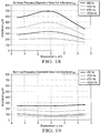
- Figure 16 is a graph of simulated frequency dependent voice coil resistance R eff as a function of displacement for a loudspeaker embodiment with an aluminum frame as a conducting element
- Figure 17 is a graph of simulated frequency dependent voice coil resistance R eff as a function of displacement for a loudspeaker embodiment with an aluminum frame, copper ring, copper cap and aluminum rings as conducting elements.
- the four conducting element loudspeaker embodiment shows a significant improvement of linearity.
- Figure 18 is a graph of simulated frequency-dependent voice coil inductance L eff as a function of displacement for a loudspeaker embodiment with an aluminum frame as a conducting element
- Figure 19 is a graph of simulated frequency-dependent voice coil inductance L eff as a function of displacement for a loudspeaker embodiment with an aluminum frame, copper ring, copper cap and aluminum rings as conducting elements.
- Figure 18 with an increase in frequency, the zero-position value of inductance decreases as well as the dependence of the inductance on displacement.
- Figure 19 shows overall lower levels of the inductance compared with the embodiment of Figure 18 , and lower dependence of the inductance on frequency and the improvement of linearity are also observed.
- the electrodynamic loudspeaker described herein has a very low dependence of the voice coil inductance on displacement and current, while providing a very low "linear" level of the inductance.
- the embodiments may be used, but not limited to, in various generations of transducers for loudspeaker systems where a high level of performance is needed, for example, in touring, portable, studio monitors, installed sound professional loudspeakers, automotive and consumer loudspeakers.
- a loudspeaker that is optimized with the plurality of conductive elements as described herein not only has a very linear inductance (e.g., as a function of the voice coil displacement and current), but it also has very low zero-displacement value of the inductance which significantly decreases the modulation of the permanent magnetic flux in the voice coil gap, and reduces the impedance increase towards higher frequencies. These effects help to reduce the distortion generated by the motor to a minimum even at high amplitudes of the input signal where displacement of the voice coil may be significant.
Description
- This application claims the benefit of
U.S. provisional application Serial No. 61/861,145 filed August 1, 2013 - Embodiments relate to electrodynamic loudspeakers having conducting elements.
- An electrodynamic motor includes a magnet assembly that generates a constant magnetic field in a magnetic air gap and the voice coil immersed in the gap. An alternating current corresponding to electrical signals conveying audio signals interacts with the constant magnetic field. This interaction results in the Laplace force F, expressed as a product of the magnetic flux density B, the overall length of the voice coil's turns linked to the magnetic flux l, and the value of the electrical current running through the voice coil i, F=Bli. Due to the Laplace force acting on the voice coil wire positioned in the constant magnetic field, the alternating current actuates the voice coil to move back and forth in the magnetic air gap and, correspondingly, move the diaphragm to which the coil (or coil former) is attached. Accordingly, the reciprocating voice coil actuates the diaphragm to likewise reciprocate and, consequently, produce acoustic signals that propagate as sound waves through air.
- Typically, the product Bl (called the force factor) is a function of the voice coil position in the voice coil gap: Bl(x), as shown in
Figure 1 . The typical dependence of the Bl-product on displacement is essentially that of a soft limiter and remains almost constant at low levels of signal, thus producing minimum nonlinear distortion. In addition, the voice coil inductance is a function of the voice coil's position and it also depends on the instantaneous value of the current: L vc(x, i), as shown inFigures 2 and3 , respectively, even at very small levels of signal. These latter two nonlinear parameters are major sources of nonlinear distortion in an electrodynamic loudspeaker. When the voice coil is in the inward position, it is surrounded by steel parts of the motor and its inductance is higher compared to the outward protruding position when part of the voice coil is surrounded by air. When the high-level current runs through the voice coil, it may saturate parts of the steel adjacent to the voice coil. Saturated steel has lower magnetic permeability and therefore the voice coil inductance decreases. - In general, operation of an electrodynamic loudspeaker is described by two nonlinear ordinary differential equations (W. Klippel, "Measurement of Large Signal Parameters of Electrodynamic Transducer", presented at the 107st Convention of the Audio Engineering Society, preprint 5008, September 1999).
- One of the equations describes the balance of forces:

where m ms is the moving mass, R ms is the mechanical losses, and K ms(x) is the suspension's mechanical stiffness. - The second equation describes the balance of voltages for the case when the loudspeaker is driven by an amplifier with negligibly small output impedance, where R vc is the simple resistance and L vc is the ideal inductance that does not depend on frequency:

- As it follows from the equations (1) and (2), the nonlinearities coming from the terms Bl(x) and Lve (x,i) are dominant. It is important to minimize dependence of these parameters on displacement and current.
- In reality, the impedance of a loudspeaker voice coil does not only contain a simple resistance R vc and an ideal inductance L vc. Since the voice coil is surrounded by ferromagnetic and conductive materials, the voice coil impedance also incorporates magnetic losses and eddy currents. Thus, the ideal inductive element ZL =jωL vc should be replaced by the complex and frequency dependent element:

where L eff is the frequency dependent inductance and R eff describes the electrical and magnetic losses due to the material surrounding the voice coil. - There are various existing methods that attempt to linearize the Bl-product and the voice coil inductance. The most popular methods are using either an overhung voice coil or an underhung voice coil (Gander M, J. Audio Eng. Soc., vol. 29, pp. 10-26, 1981, Jan./Feb). With an overhung voice coil, the electrodynamic linkage occurs only in a small part of the voice coil. With an underhung voice coil, the linkage is provided in a small part of the top plate and pole piece. Another prior method includes the use of an uneven winding of the voice coil (Olson H, Van Nostrand Reinhold, 1972, pp. 23-25; Mazin V and Sang Lee Y, 116th AES Convention, preprint 6152, 2004, Berlin). This method requires more turns at the peripheries of the voice coil, and also requires a wider gap to accommodate extra layers of peripheral turns and more complexity in fabricating the voice coil. Another prior approach is proposed in
U.S. Patent No. 7,283,642 , wherein the underhung voice coil and the top plate and pole piece have cavities. The cavities are positioned against the central position of the voice coil. However, as the voice coil moves out of the gap, the Bl product remains flat because the loss of the magnetic linkage is compensated by the increased induction B. - One method to minimize variation of the alternating magnetic flux produced by the voice coil, and correspondingly, to minimize the voice coil inductance value at a zero position, as well as to minimize the dependence of the voice coil inductance on the coil's position and current involves implementing a selected conducting element. For example, conductive plating may be provided on a pole piece, a conductive cap may be provided over the pole piece, and a conductive ring may be used (Gander M, J. Audio Eng. Soc., vol. 29, pp. 10-26, 1981, Jan./Feb). The conductive elements act as a single-turn secondary winding of a transformer. The alternating current generated in the "secondary" turn produces an alternating current. This current generates an alternating magnetic flux opposite in sign to the flux generated by the voice coil and therefore decreases it. Such methods may be directed to minimizing the voice coil dependence on current and may decrease the absolute value of the inductance. However, they may not improve linearity of the voice coil inductance as a function of displacement.
- An alternative approach to minimize variation of the voice coil alternating flux is using active compensation (Carlisi M et al., 118th AES Convention, preprint 6421, 2005, Barcelona). In this method, instead of using a single-turn conductive element, a multi-turn stationary coil is used. It makes possible various ways of driving the secondary coil, such as driving it with an additional amplifier, driving it in parallel with the voice coil from a single amplifier, driving it through the filter that shapes the driving level with the frequency, and simply shorting the stationary coil. Further approaches are known, e.g., from
WO 99/48329 A1 US 3 830 986 A andWO 94/27413A1 - The nonlinearity that distorts a signal at its low levels is especially detrimental to the audible sound quality. Therefore, it is important to keep the "linear" value of the voice coil inductance as well as its variation on displacement and current low to minimize the flux modulation and to decrease the high-frequency attenuation cause by the impedance's inductive component.
- In one embodiment, a loudspeaker includes a motor assembly including a disk or annular magnet having a first face and a second face, a back plate abutting the magnet first face, a pole piece centrally disposed with respect to the back plate and extending upwardly beyond the magnet second face, and a top plate concentrically disposed with respect to the pole piece abutting one of the magnet or the back plate and extending upwardly beyond the magnet second face. A non-magnetic electrically conducting frame is attached to the top plate, a non-magnetic electrically conducting cap is disposed within the motor assembly and encircling the pole piece, a first non-magnetic electrically conducting ring is disposed within the top plate or the pole piece and encircling the pole piece, and at least one second non-magnetic electrically conducting ring is disposed within the motor assembly and abutting the back plate.
- In another embodiment, a loudspeaker includes a motor assembly including a magnet having a first face and a second face, a back plate abutting the magnet first face, a pole piece abutting the magnet second face, and a top plate concentrically disposed with respect to the pole piece and abutting the back plate. A frame is attached to the top plate and at least partially formed of aluminum, a copper cap is disposed within the motor assembly and encircling the pole piece, a copper ring is disposed within the motor assembly and encircling the pole piece, and at least one aluminum ring is disposed within the motor assembly and abutting the back plate.
- In another embodiment, a loudspeaker includes a motor assembly including a back plate, a pole piece centrally mounted on the back plate, a top plate concentrically disposed about the pole piece, and a magnet concentrically disposed about the pole piece between the back plate and the top plate. A frame is attached to the top plate and at least partially formed from aluminum, a copper cap is disposed within the motor assembly and encircling the pole piece, a copper ring is disposed within the motor assembly and encircling the pole piece, and at least one aluminum ring is disposed within the motor assembly and abutting the back plate.
-
-
Figure 1 is a graph of the dependence of the force factor Bl-product on the position of the voice coil; -
Figure 2 is a graph of the dependence of the voice coil inductance on the position of the voice coil; -
Figure 3 is a graph of the dependence of the voice coil inductance on the voice coil current; -
Figure 4 is a cross-sectional view of a loudspeaker embodiment having an internal magnet and conducting elements; -
Figure 5 is a cross-sectional view of a loudspeaker embodiment having an internal magnet and conducting elements, illustrating an alternative position of an aluminum ring; -
Figure 6 is a cross-sectional view of a loudspeaker embodiment having an internal magnet and conducting elements, illustrating an alternative position of a copper ring; -
Figure 7 is a cross-sectional view of a loudspeaker embodiment having an internal magnet and conducting elements, illustrating an alternative position of a copper cap; -
Figure 8 is a cross-sectional view of a loudspeaker embodiment having an external magnet and conducting elements; - *
Figure 9 is a cross-sectional view of a loudspeaker embodiment having an external magnet and conducting elements, illustrating concentric external and internal aluminum rings; -
Figure 10 is a cross-sectional view of a loudspeaker embodiment having an external magnet and conducting elements, including an additional aluminum ring; -
Figure 11 is a graph of the measured voice coil inductance as a function of displacement for a loudspeaker embodiment with only an aluminum frame as a conducting element; -
Figure 12 is a graph of the measured voice coil inductance as a function of displacement for a loudspeaker embodiment with an aluminum frame and copper ring as conducting elements; -
Figure 13 is a graph of the measured voice coil inductance as a function of displacement for a loudspeaker embodiment with an aluminum frame, a copper ring, and an aluminum ring as conducting elements; -
Figure 14 is a graph of the measured voice coil inductance as a function of displacement for a loudspeaker embodiment with an aluminum frame, a copper ring, an aluminum ring and a copper cap as conducting elements; -
Figure 15 is a graph depicting the decrease of the blocked voice coil impedance at high frequencies as a result of adding electrical current shorting elements to the motor, where the top curve is for a loudspeaker embodiment with only an aluminum frame as a conducting element, the middle curve is for a loudspeaker embodiment with an aluminum frame and copper ring as conducting elements, and the bottom curve is for a loudspeaker embodiment with an aluminum frame, a copper ring, a copper cap, and aluminum ring as conducting elements; -
Figure 16 is a graph of simulated frequency dependent voice coil resistance R eff as a function of displacement for a loudspeaker embodiment with only an aluminum frame as a conducting element; -
Figure 17 is a graph of simulated frequency dependent voice coil resistance R eff as a function of displacement for a loudspeaker embodiment with an aluminum frame, a copper ring, a copper cap and an aluminum ring as conducting elements; -
Figure 18 is a graph of simulated frequency-dependent voice coil inductance L eff as a function of displacement for a loudspeaker embodiment with an aluminum frame as a conducting element; and -
Figure 19 is a graph of simulated frequency-dependent voice coil inductance L eff as a function of displacement for a loudspeaker embodiment with an aluminum frame, copper ring, copper cap and aluminum rings as conducting elements. - As required, detailed embodiments of the present invention are disclosed herein; however, it is to be understood that the disclosed embodiments are merely exemplary of the invention that may be embodied in various and alternative forms. The figures are not necessarily to scale; some features may be exaggerated or minimized to show details of particular components. Therefore, specific structural and functional details disclosed herein are not to be interpreted as limiting, but merely as a representative basis for teaching one skilled in the art to variously employ the present invention.
- Various embodiments as disclosed herein include a plurality of conductive elements in the voice coil gap and around its vicinity to linearize the force factor Bl as a function of the voice coil position Bl(x), and the voice coil inductance L vc as a function of the coil's position L vc(x) and the function of the voice coil's current Lvc (i). In addition to being a very linear function of the coil's position and the current, the absolute value of the voice coil's inductance L vc is very low.
-
Figure 4 is a cross-sectional view of aloudspeaker 10 having an internal magnet and a plurality of conducting elements.Loudspeaker 10 generally comprises aframe 12, amotor assembly 14, a voice coil and former 16, and a cone (or diaphragm) anddust cap 18. Theloudspeaker 10 may also include other components, such as a spider (not shown), as is known in the art. - The
motor assembly 14 includes apermanent magnet 20, such as a neodymium internal magnet, where themagnet 20 has afirst face 22 and asecond face 24. Themotor assembly 14 further includes aback plate 26 abutting the magnetfirst face 22, and apole piece 28 centrally disposed with respect to theback plate 26, abutting the magnetsecond face 24 and extending beyond the magnetsecond face 24. Atop plate 30 is concentrically disposed with respect to thepole piece 28, abutting theback plate 26 and extending beyond the magnetsecond face 24. Theback plate 26 could also be defined as a shellpot structure with a pot wall attached to the back plate and a magnet received in the shellpot. Amagnetic gap 31 is formed between thepole piece 28 andtop plate 30 within which thevoice coil 16 is axially movable. - With continuing reference to
Figure 4 , theframe 12 is constructed from a non-magnetic conducting material, wherein in one embodiment at least a portion of theframe 12 comprises aluminum, or may alternatively comprise copper. The lower part of theframe 12 adjacent to thevoice coil 16 behaves similar to a shorting ring, and theframe 12 provides linearization and symmetry of the alternating flux and, correspondingly, the voice coil's inductance. - The
top plate 30 may include agroove 32 formed along aninner surface 33 thereof which linearizes the force factor Bl(x) and can receive a firstnon-magnetic conducting ring 34. In one embodiment, thefirst ring 34 comprises copper. Any dimensions and geometry of thefirst ring 34 appropriate for a particular loudspeaker may be utilized.Figure 6 illustrates an alternative position of thefirst ring 34 disposed within thepole piece 28. In both the embodiments ofFigure 4 andFigure 6 , thefirst ring 34 is disposed within themotor assembly 14 so as to encircle thepole piece 28. - In addition, the
loudspeaker 10 may include anon-magnetic conducting cap 36 disposed within themotor assembly 14 and encircling thepole piece 28. In one embodiment, thecap 36 comprises copper. Thecap 36 may abut two adjacent surfaces within themotor assembly 14 and may have a thickness of approximately 0.01 inches. However, any dimensions and geometry of thecap 36 appropriate for a particular loudspeaker may be utilized. In the embodiment ofFigure 4 , thecap 36 abuts a portion of thepole piece 28, covering the surface of thepole piece 28 adjacent to thevoice coil gap 31. In the embodiment ofFigure 7 , thecap 36 instead abuts a portion of thetop plate 30. - Referring again to
Figure 4 , at least one second non-magnetic conductingring 38 may be disposed within themotor assembly 14 abutting theback plate 26. In one embodiment, thesecond ring 38 may comprise aluminum and, as for the other conducting elements described above, can have any dimensions and geometry suitable for a particular loudspeaker implementation. In the configuration depicted inFigure 4 , thesecond ring 38 is positioned to be spaced from themagnet 20.Figure 5 illustrates an alternative position of thesecond ring 38 abutting themagnet 20. -
Figure 8 is a cross-sectional view of aloudspeaker 110 having an external magnet and a plurality of conducting elements, wherein features ofloudspeaker 110 similar toloudspeaker 10 are identified with like reference numerals with the addition of a "1" prefix. As above,loudspeaker 110 generally comprises aframe 112, amotor assembly 114, a voice coil and former 116, and a cone (or diaphragm) anddust cap 118. As above, theloudspeaker 110 may also include other components, such as a spider (not shown), as is known in the art. - The
motor assembly 114 includes apermanent magnet 120, such as a ferrite, neodymium, or Alnico external magnet, where themagnet 120 has a first face 122 and a second face 124. Themotor assembly 114 further includes aback plate 126 abutting the magnet first face 122, and apole piece 128 centrally mounted with respect to theback plate 126 extending beyond the magnet second face 124. Atop plate 130 is concentrically disposed with respect to thepole piece 128 and extending beyond the magnet second face 124. Themagnet 120 is concentrically disposed about thepole piece 128 between theback plate 126 and thetop plate 130. A magnetic gap is formed between thepole piece 128 andtop plate 130 within which thevoice coil 116 is axially movable. -
Figure 8 illustrates aloudspeaker 110 having the conducting elements described above, namely theframe 112,first ring 134,cap 136 andsecond ring 138, where it is understood that any of the conducting elements can have alternate positioning as described with reference toloudspeaker 10.Figures 9 and 10 depict further alternatives for conducting elements with reference toloudspeaker 110, although these alternatives are equally applicable to the embodiment ofloudspeaker 10. - With reference to
Figure 9 , concentric and spaced external 138' and internal 138" second rings. In one embodiment, the internalsecond ring 138" abuts themagnet 120 and the external second ring 138' abuts thepole piece 128.Figure 10 illustrates an embodiment ofloudspeaker 110 which includes a thirdnon-magnetic conducting ring 140, which may comprise aluminum, abutting a top surface 142 of thepole piece 128. - Again, it is understood that the loudspeaker embodiments are not limited to those depicted herein, and that the placement of conducting elements within any embodiment can be interchanged and combined to form other embodiments.
- The overall result is the increased linearity of the force Bl(x)i driving the
voice coil 16 and minimization of the constant magnetic flux modulation due to the small value and linearity of the voice coil inductance L vc(x, i). This provides minimization of the corresponding nonlinear voltage term: dL vc(x, i)/dxdi as well as the nonlinear force term responsible for the reluctance force: 0.5·(dL vc(x, i)/dx)·i2 (seeequations 1 and 2). - Each conducting element contributes to the decrease of inductance and resistive losses associated with alternating magnetic flux. The
aluminum ring 38 may not decrease the resistive losses at rest position since thecopper elements copper cap 36 and thecopper ring 34. Symmetry of the inductance L vc(x) is provided by the balance between the alternating flux generated by the lower part of theframe 12 and the alternating flux generated by thealuminum ring 38. -
Figures 11-14 are graphs of the measured voice coil inductance as a function of displacement for a loudspeaker embodiment with an aluminum frame as a conducting element (Fig. 11 ), a loudspeaker embodiment with an aluminum frame and copper ring as conducting elements (Fig. 12 ), a loudspeaker embodiment with an aluminum frame, a copper ring, and an aluminum ring as conducting elements (Fig. 13 ), and a loudspeaker embodiment with an aluminum frame, a copper ring, an aluminum ring and a copper cap as conducting elements (Fig. 14 ). Significant linearization of the voice coil inductance is observed with the addition of conducting elements. - The reduced inductance also has significant influence on the electrical impedance of the voice coil, which is illustrated in the graph of
Figure 15 for different loudspeaker embodiments with the voice coil blocked in the center of the gap, where the top curve is for a loudspeaker embodiment with only an aluminum frame as a conducting element, the middle curve is for a loudspeaker embodiment with an aluminum frame and copper ring as conducting elements, and the bottom curve is for a loudspeaker embodiment with an aluminum frame, a copper ring, a copper cap, and aluminum ring as conducting elements. The lower absolute value of the impedance at higher frequencies helps to increase the high frequency output. - Finite element simulations allow for a detailed view of the magnetic losses of the inductance, and the dynamic simulation results can be decomposed to the frequency dependent inductance L eff(f,x) and resistive losses R eff(f,x).
-
Figure 16 is a graph of simulated frequency dependent voice coil resistance R eff as a function of displacement for a loudspeaker embodiment with an aluminum frame as a conducting element, andFigure 17 is a graph of simulated frequency dependent voice coil resistance R eff as a function of displacement for a loudspeaker embodiment with an aluminum frame, copper ring, copper cap and aluminum rings as conducting elements. InFigure 16 , with an increase of frequency, at the zero-position the resistance increases and the dependence on the voice coil position increases as well. InFigure 17 , a lower dependence of the resistance on frequency can be observed, hence the overall level of the resistance is lower. This is indicative of the eddy currents running through more of the non-magnetic conducting materials (copper and aluminum). Thus, lower power is dissipated in the steel parts, and correspondingly, the temperature of the motor assembly at large levels of input signal will be lower as well and power handling increased. Besides the effect of the overall lower resistance, the four conducting element loudspeaker embodiment also shows a significant improvement of linearity. -
Figure 18 is a graph of simulated frequency-dependent voice coil inductance L eff as a function of displacement for a loudspeaker embodiment with an aluminum frame as a conducting element, andFigure 19 is a graph of simulated frequency-dependent voice coil inductance L eff as a function of displacement for a loudspeaker embodiment with an aluminum frame, copper ring, copper cap and aluminum rings as conducting elements. InFigure 18 , with an increase in frequency, the zero-position value of inductance decreases as well as the dependence of the inductance on displacement.Figure 19 shows overall lower levels of the inductance compared with the embodiment ofFigure 18 , and lower dependence of the inductance on frequency and the improvement of linearity are also observed. - As such, the electrodynamic loudspeaker described herein has a very low dependence of the voice coil inductance on displacement and current, while providing a very low "linear" level of the inductance. The embodiments may be used, but not limited to, in various generations of transducers for loudspeaker systems where a high level of performance is needed, for example, in touring, portable, studio monitors, installed sound professional loudspeakers, automotive and consumer loudspeakers.
- A loudspeaker that is optimized with the plurality of conductive elements as described herein not only has a very linear inductance (e.g., as a function of the voice coil displacement and current), but it also has very low zero-displacement value of the inductance which significantly decreases the modulation of the permanent magnetic flux in the voice coil gap, and reduces the impedance increase towards higher frequencies. These effects help to reduce the distortion generated by the motor to a minimum even at high amplitudes of the input signal where displacement of the voice coil may be significant.
- Conventional implementations such as a single copper cap, copper ring, or aluminum ring are targeted toward minimizing the voice coil dependence on the current and they decrease the absolute value of the inductance, but they do not necessarily decrease dependence of the voice coil inductance on the displacement. The embodiments as disclosed herein provide for a unique combination of individual current-conductive elements and their geometry and position in the motor are optimized by the dynamic finite element analysis.
Claims (14)
- A loudspeaker (10, 100) comprising:a motor assembly (14, 114) includinga disk or annular magnet (20, 120) having a first face (22) and a second face (24), a back plate (26, 126) abutting the magnet first face (22),a pole piece (28, 128) centrally disposed with respect to the back plate (26, 126) and extending upwardly beyond the magnet second face (24), anda top plate (30, 130) concentrically disposed with respect to the pole piece (28, 128)abutting either the second face of the magnet (20, 120) if an annular magnet is provided or the back plate (26, 126) if a disk magnet is provided, and extending upwardlybeyond the magnet second face (24);a non-magnetic electrically conducting frame (12, 112) attached to the top plate (30, 130);a non-magnetic electrically conducting cap (36, 136) disposed within the motor assembly (14, 114) and encircling the pole piece (28, 128);a first non-magnetic electrically conducting ring (34, 134) disposed within the top plate (30, 130) or the pole piece (28, 128) and encircling the pole piece (28, 128); andat least one second non-magnetic electrically conducting ring (38, 138) disposed within the motor assembly (14, 114) and abutting the back plate (26, 126).
- The loudspeaker of claim 1, wherein the top plate (30, 130) includes a groove (32, 132) formed along an inner surface (33, 133) thereof, and the first ring (34, 134) is disposed in the groove (32, 132).
- The loudspeaker of claim 1, wherein the first ring (34, 134) comprises copper.
- The loudspeaker of claim 1, wherein the cap (36, 136) abuts two adjacent surfaces within the motor assembly (14, 114).
- The loudspeaker of claim 1, wherein the cap (36, 136) abuts a portion of the pole piece (28, 128).
- The loudspeaker of claim 1, wherein the cap (36, 136) abuts a portion of the top plate (30, 130).
- The loudspeaker of claim 1, wherein the cap (36, 136) comprises copper.
- The loudspeaker of claim 1, wherein the at least one second ring (38, 138) abuts the magnet (20, 120).
- The loudspeaker of claim 1, wherein the at least one second ring (38, 138) abuts the pole piece (28, 128).
- The loudspeaker of claim 1, wherein the at least one second ring includes an external second ring (138') concentric with and spaced from an internal second ring (138").
- The loudspeaker of claim 1, wherein at least one second ring (38, 138) comprises aluminum.
- The loudspeaker of claim 1, further comprising a third non-magnetic electrically conducting ring (140) abutting a top surface (142) of the pole piece (128).
- The loudspeaker of claim 1, wherein the third ring (140) comprises aluminum.
- The loudspeaker of claim 1, wherein the frame (12, 112) comprises aluminum.
Applications Claiming Priority (1)
| Application Number | Priority Date | Filing Date | Title |
|---|---|---|---|
| US201361861145P | 2013-08-01 | 2013-08-01 |
Publications (3)
| Publication Number | Publication Date |
|---|---|
| EP2833648A2 EP2833648A2 (en) | 2015-02-04 |
| EP2833648A3 EP2833648A3 (en) | 2015-03-18 |
| EP2833648B1 true EP2833648B1 (en) | 2016-04-27 |
Family
ID=51257436
Family Applications (1)
| Application Number | Title | Priority Date | Filing Date |
|---|---|---|---|
| EP14179579.9A Active EP2833648B1 (en) | 2013-08-01 | 2014-08-01 | Electrodynamic loudspeaker with conducting elements |
Country Status (2)
| Country | Link |
|---|---|
| US (1) | US9100738B2 (en) |
| EP (1) | EP2833648B1 (en) |
Families Citing this family (9)
| Publication number | Priority date | Publication date | Assignee | Title |
|---|---|---|---|---|
| US20100246880A1 (en) * | 2009-03-30 | 2010-09-30 | Oxford J Craig | Method and apparatus for enhanced stimulation of the limbic auditory response |
| US20160134982A1 (en) * | 2014-11-12 | 2016-05-12 | Harman International Industries, Inc. | System and method for estimating the displacement of a speaker cone |
| CN110383858B (en) | 2017-03-07 | 2022-07-05 | 哈曼国际工业有限公司 | Loudspeaker |
| CN111819866B (en) | 2018-03-07 | 2023-02-03 | 哈曼国际工业有限公司 | Loudspeaker |
| CN208821073U (en) * | 2018-10-15 | 2019-05-03 | 苏州上声电子股份有限公司 | A kind of magnetic circuit of loudspeaker and loudspeaker |
| KR20200069132A (en) * | 2018-12-06 | 2020-06-16 | 현대자동차주식회사 | Yoke for speaker, Method form manufacturing the same And Speaker device including the same |
| CN209861150U (en) * | 2018-12-31 | 2019-12-27 | 瑞声光电科技(常州)有限公司 | Sound production device |
| GB2591223A (en) * | 2020-01-22 | 2021-07-28 | Gp Acoustics International Ltd | Loudspeakers |
| WO2022049156A1 (en) * | 2020-09-03 | 2022-03-10 | Purifi Aps | Loudspeaker motor with inner permanent magnet |
Family Cites Families (8)
| Publication number | Priority date | Publication date | Assignee | Title |
|---|---|---|---|---|
| JPS5235294B2 (en) * | 1971-12-17 | 1977-09-08 | ||
| US5815587A (en) * | 1993-05-10 | 1998-09-29 | Scan-Speak A/S | Loudspeaker with short circuit rings at the voice coil |
| DK54093D0 (en) | 1993-05-10 | 1993-05-10 | Scan Speak As | SPEAKER |
| US6768806B1 (en) * | 1998-03-19 | 2004-07-27 | Harman International Industries, Incorporated | Shorting rings in dual-coil dual-gap loudspeaker drivers |
| ATE414395T1 (en) | 1998-03-19 | 2008-11-15 | Jbl Inc | SHORT CIRCUIT RINGS FOR SPEAKER DRIVE WITH DOUBLE COILS AND DOUBLE COLUMNS |
| FR2836000B1 (en) | 2002-02-13 | 2004-05-28 | Harman Internat | ELECTRODYNAMIC MOTOR WITH MOBILE COIL, PARTICULARLY FOR SPEAKER, SPEAKER AND ADAPTED POLAR PART |
| US7272238B2 (en) * | 2004-10-12 | 2007-09-18 | Alpine Electronics, Inc. | Loudspeaker having cooling system |
| US7929726B1 (en) * | 2006-12-27 | 2011-04-19 | Jones Philip K G | Planar diaphragm acoustic loudspeaker |
-
2014
- 2014-08-01 EP EP14179579.9A patent/EP2833648B1/en active Active
- 2014-08-01 US US14/449,644 patent/US9100738B2/en active Active
Also Published As
| Publication number | Publication date |
|---|---|
| US9100738B2 (en) | 2015-08-04 |
| EP2833648A2 (en) | 2015-02-04 |
| EP2833648A3 (en) | 2015-03-18 |
| US20150078610A1 (en) | 2015-03-19 |
Similar Documents
| Publication | Publication Date | Title |
|---|---|---|
| EP2833648B1 (en) | Electrodynamic loudspeaker with conducting elements | |
| EP3429228B1 (en) | Speaker and headphone | |
| CN102387451B (en) | Split magnet loudspeaker | |
| US7706563B2 (en) | Concentric radial ring motor | |
| TW201941621A (en) | Panel audio loudspeaker electromagnetic actuator | |
| AU2009242055B2 (en) | Ironless and leakage free coil transducer motor assembly | |
| KR20110063792A (en) | Methods and apparatus for reduced distortion balanced armature devices | |
| JPH0591592A (en) | Conversion with permanent magnet | |
| KR102460601B1 (en) | Multi-engine array system and speakers | |
| US20030133587A1 (en) | Speaker driver | |
| JP2011030013A (en) | Moving-magnet type speaker and method of manufacturing the same | |
| JP5191796B2 (en) | Speaker | |
| US7873180B2 (en) | Voice coil actuator | |
| US20230117602A1 (en) | Improvements in and relating to loudspeaker magnet assemblies | |
| US11956612B2 (en) | Loudspeaker motor with improved linearity | |
| US20230362547A1 (en) | Loudspeaker motor with inner permanent magnet | |
| JP3961960B2 (en) | Speaker | |
| US11290823B2 (en) | Double voice coil loudspeaker transducer unit | |
| CN219204661U (en) | Moving-magnet vibrator with parallel magnet coils and nonlinear term offset | |
| CN105376681A (en) | Planar coil driven film loudspeaker | |
| Merit et al. | Enhanced construction of the direct radiator electrodynamic loudspeaker | |
| CN107534814B (en) | Speaker device and method for improving sound quality of speaker device | |
| RU148952U1 (en) | DYNAMIC SPEAKER | |
| JP2010004421A (en) | Electroacoustic transducer | |
| JP2006500810A (en) | Electromechanical transducer |
Legal Events
| Date | Code | Title | Description |
|---|---|---|---|
| 17P | Request for examination filed |
Effective date: 20140801 |
|
| AK | Designated contracting states |
Kind code of ref document: A2 Designated state(s): AL AT BE BG CH CY CZ DE DK EE ES FI FR GB GR HR HU IE IS IT LI LT LU LV MC MK MT NL NO PL PT RO RS SE SI SK SM TR |
|
| AX | Request for extension of the european patent |
Extension state: BA ME |
|
| PUAI | Public reference made under article 153(3) epc to a published international application that has entered the european phase |
Free format text: ORIGINAL CODE: 0009012 |
|
| PUAL | Search report despatched |
Free format text: ORIGINAL CODE: 0009013 |
|
| AK | Designated contracting states |
Kind code of ref document: A3 Designated state(s): AL AT BE BG CH CY CZ DE DK EE ES FI FR GB GR HR HU IE IS IT LI LT LU LV MC MK MT NL NO PL PT RO RS SE SI SK SM TR |
|
| AX | Request for extension of the european patent |
Extension state: BA ME |
|
| RIC1 | Information provided on ipc code assigned before grant |
Ipc: H04R 9/02 20060101AFI20150206BHEP |
|
| R17P | Request for examination filed (corrected) |
Effective date: 20150911 |
|
| RBV | Designated contracting states (corrected) |
Designated state(s): AL AT BE BG CH CY CZ DE DK EE ES FI FR GB GR HR HU IE IS IT LI LT LU LV MC MK MT NL NO PL PT RO RS SE SI SK SM TR |
|
| GRAP | Despatch of communication of intention to grant a patent |
Free format text: ORIGINAL CODE: EPIDOSNIGR1 |
|
| INTG | Intention to grant announced |
Effective date: 20151118 |
|
| GRAS | Grant fee paid |
Free format text: ORIGINAL CODE: EPIDOSNIGR3 |
|
| GRAA | (expected) grant |
Free format text: ORIGINAL CODE: 0009210 |
|
| AK | Designated contracting states |
Kind code of ref document: B1 Designated state(s): AL AT BE BG CH CY CZ DE DK EE ES FI FR GB GR HR HU IE IS IT LI LT LU LV MC MK MT NL NO PL PT RO RS SE SI SK SM TR |
|
| REG | Reference to a national code |
Ref country code: GB Ref legal event code: FG4D |
|
| REG | Reference to a national code |
Ref country code: CH Ref legal event code: EP |
|
| REG | Reference to a national code |
Ref country code: AT Ref legal event code: REF Ref document number: 795929 Country of ref document: AT Kind code of ref document: T Effective date: 20160515 |
|
| REG | Reference to a national code |
Ref country code: IE Ref legal event code: FG4D |
|
| REG | Reference to a national code |
Ref country code: DE Ref legal event code: R096 Ref document number: 602014001682 Country of ref document: DE |
|
| REG | Reference to a national code |
Ref country code: LT Ref legal event code: MG4D |
|
| REG | Reference to a national code |
Ref country code: NL Ref legal event code: MP Effective date: 20160427 |
|
| REG | Reference to a national code |
Ref country code: AT Ref legal event code: MK05 Ref document number: 795929 Country of ref document: AT Kind code of ref document: T Effective date: 20160427 |
|
| PG25 | Lapsed in a contracting state [announced via postgrant information from national office to epo] |
Ref country code: NL Free format text: LAPSE BECAUSE OF FAILURE TO SUBMIT A TRANSLATION OF THE DESCRIPTION OR TO PAY THE FEE WITHIN THE PRESCRIBED TIME-LIMIT Effective date: 20160427 |
|
| PG25 | Lapsed in a contracting state [announced via postgrant information from national office to epo] |
Ref country code: LT Free format text: LAPSE BECAUSE OF FAILURE TO SUBMIT A TRANSLATION OF THE DESCRIPTION OR TO PAY THE FEE WITHIN THE PRESCRIBED TIME-LIMIT Effective date: 20160427 Ref country code: NO Free format text: LAPSE BECAUSE OF FAILURE TO SUBMIT A TRANSLATION OF THE DESCRIPTION OR TO PAY THE FEE WITHIN THE PRESCRIBED TIME-LIMIT Effective date: 20160727 Ref country code: FI Free format text: LAPSE BECAUSE OF FAILURE TO SUBMIT A TRANSLATION OF THE DESCRIPTION OR TO PAY THE FEE WITHIN THE PRESCRIBED TIME-LIMIT Effective date: 20160427 Ref country code: PL Free format text: LAPSE BECAUSE OF FAILURE TO SUBMIT A TRANSLATION OF THE DESCRIPTION OR TO PAY THE FEE WITHIN THE PRESCRIBED TIME-LIMIT Effective date: 20160427 |
|
| PG25 | Lapsed in a contracting state [announced via postgrant information from national office to epo] |
Ref country code: RS Free format text: LAPSE BECAUSE OF FAILURE TO SUBMIT A TRANSLATION OF THE DESCRIPTION OR TO PAY THE FEE WITHIN THE PRESCRIBED TIME-LIMIT Effective date: 20160427 Ref country code: AT Free format text: LAPSE BECAUSE OF FAILURE TO SUBMIT A TRANSLATION OF THE DESCRIPTION OR TO PAY THE FEE WITHIN THE PRESCRIBED TIME-LIMIT Effective date: 20160427 Ref country code: PT Free format text: LAPSE BECAUSE OF FAILURE TO SUBMIT A TRANSLATION OF THE DESCRIPTION OR TO PAY THE FEE WITHIN THE PRESCRIBED TIME-LIMIT Effective date: 20160829 Ref country code: LV Free format text: LAPSE BECAUSE OF FAILURE TO SUBMIT A TRANSLATION OF THE DESCRIPTION OR TO PAY THE FEE WITHIN THE PRESCRIBED TIME-LIMIT Effective date: 20160427 Ref country code: GR Free format text: LAPSE BECAUSE OF FAILURE TO SUBMIT A TRANSLATION OF THE DESCRIPTION OR TO PAY THE FEE WITHIN THE PRESCRIBED TIME-LIMIT Effective date: 20160728 Ref country code: HR Free format text: LAPSE BECAUSE OF FAILURE TO SUBMIT A TRANSLATION OF THE DESCRIPTION OR TO PAY THE FEE WITHIN THE PRESCRIBED TIME-LIMIT Effective date: 20160427 Ref country code: SE Free format text: LAPSE BECAUSE OF FAILURE TO SUBMIT A TRANSLATION OF THE DESCRIPTION OR TO PAY THE FEE WITHIN THE PRESCRIBED TIME-LIMIT Effective date: 20160427 Ref country code: ES Free format text: LAPSE BECAUSE OF FAILURE TO SUBMIT A TRANSLATION OF THE DESCRIPTION OR TO PAY THE FEE WITHIN THE PRESCRIBED TIME-LIMIT Effective date: 20160427 |
|
| PG25 | Lapsed in a contracting state [announced via postgrant information from national office to epo] |
Ref country code: BE Free format text: LAPSE BECAUSE OF FAILURE TO SUBMIT A TRANSLATION OF THE DESCRIPTION OR TO PAY THE FEE WITHIN THE PRESCRIBED TIME-LIMIT Effective date: 20160427 Ref country code: IT Free format text: LAPSE BECAUSE OF FAILURE TO SUBMIT A TRANSLATION OF THE DESCRIPTION OR TO PAY THE FEE WITHIN THE PRESCRIBED TIME-LIMIT Effective date: 20160427 |
|
| REG | Reference to a national code |
Ref country code: DE Ref legal event code: R097 Ref document number: 602014001682 Country of ref document: DE |
|
| PG25 | Lapsed in a contracting state [announced via postgrant information from national office to epo] |
Ref country code: DK Free format text: LAPSE BECAUSE OF FAILURE TO SUBMIT A TRANSLATION OF THE DESCRIPTION OR TO PAY THE FEE WITHIN THE PRESCRIBED TIME-LIMIT Effective date: 20160427 Ref country code: CZ Free format text: LAPSE BECAUSE OF FAILURE TO SUBMIT A TRANSLATION OF THE DESCRIPTION OR TO PAY THE FEE WITHIN THE PRESCRIBED TIME-LIMIT Effective date: 20160427 Ref country code: SK Free format text: LAPSE BECAUSE OF FAILURE TO SUBMIT A TRANSLATION OF THE DESCRIPTION OR TO PAY THE FEE WITHIN THE PRESCRIBED TIME-LIMIT Effective date: 20160427 Ref country code: RO Free format text: LAPSE BECAUSE OF FAILURE TO SUBMIT A TRANSLATION OF THE DESCRIPTION OR TO PAY THE FEE WITHIN THE PRESCRIBED TIME-LIMIT Effective date: 20160427 Ref country code: EE Free format text: LAPSE BECAUSE OF FAILURE TO SUBMIT A TRANSLATION OF THE DESCRIPTION OR TO PAY THE FEE WITHIN THE PRESCRIBED TIME-LIMIT Effective date: 20160427 |
|
| PG25 | Lapsed in a contracting state [announced via postgrant information from national office to epo] |
Ref country code: SM Free format text: LAPSE BECAUSE OF FAILURE TO SUBMIT A TRANSLATION OF THE DESCRIPTION OR TO PAY THE FEE WITHIN THE PRESCRIBED TIME-LIMIT Effective date: 20160427 |
|
| PLBE | No opposition filed within time limit |
Free format text: ORIGINAL CODE: 0009261 |
|
| STAA | Information on the status of an ep patent application or granted ep patent |
Free format text: STATUS: NO OPPOSITION FILED WITHIN TIME LIMIT |
|
| PG25 | Lapsed in a contracting state [announced via postgrant information from national office to epo] |
Ref country code: MC Free format text: LAPSE BECAUSE OF FAILURE TO SUBMIT A TRANSLATION OF THE DESCRIPTION OR TO PAY THE FEE WITHIN THE PRESCRIBED TIME-LIMIT Effective date: 20160427 |
|
| 26N | No opposition filed |
Effective date: 20170130 |
|
| REG | Reference to a national code |
Ref country code: FR Ref legal event code: ST Effective date: 20170428 |
|
| PG25 | Lapsed in a contracting state [announced via postgrant information from national office to epo] |
Ref country code: SI Free format text: LAPSE BECAUSE OF FAILURE TO SUBMIT A TRANSLATION OF THE DESCRIPTION OR TO PAY THE FEE WITHIN THE PRESCRIBED TIME-LIMIT Effective date: 20160427 |
|
| REG | Reference to a national code |
Ref country code: IE Ref legal event code: MM4A |
|
| PG25 | Lapsed in a contracting state [announced via postgrant information from national office to epo] |
Ref country code: IE Free format text: LAPSE BECAUSE OF NON-PAYMENT OF DUE FEES Effective date: 20160801 Ref country code: FR Free format text: LAPSE BECAUSE OF NON-PAYMENT OF DUE FEES Effective date: 20160831 |
|
| PG25 | Lapsed in a contracting state [announced via postgrant information from national office to epo] |
Ref country code: LU Free format text: LAPSE BECAUSE OF NON-PAYMENT OF DUE FEES Effective date: 20160801 |
|
| REG | Reference to a national code |
Ref country code: CH Ref legal event code: PL |
|
| PG25 | Lapsed in a contracting state [announced via postgrant information from national office to epo] |
Ref country code: CH Free format text: LAPSE BECAUSE OF NON-PAYMENT OF DUE FEES Effective date: 20170831 Ref country code: LI Free format text: LAPSE BECAUSE OF NON-PAYMENT OF DUE FEES Effective date: 20170831 |
|
| PG25 | Lapsed in a contracting state [announced via postgrant information from national office to epo] |
Ref country code: HU Free format text: LAPSE BECAUSE OF FAILURE TO SUBMIT A TRANSLATION OF THE DESCRIPTION OR TO PAY THE FEE WITHIN THE PRESCRIBED TIME-LIMIT; INVALID AB INITIO Effective date: 20140801 |
|
| PG25 | Lapsed in a contracting state [announced via postgrant information from national office to epo] |
Ref country code: CY Free format text: LAPSE BECAUSE OF FAILURE TO SUBMIT A TRANSLATION OF THE DESCRIPTION OR TO PAY THE FEE WITHIN THE PRESCRIBED TIME-LIMIT Effective date: 20160427 Ref country code: MT Free format text: LAPSE BECAUSE OF NON-PAYMENT OF DUE FEES Effective date: 20160831 Ref country code: MK Free format text: LAPSE BECAUSE OF FAILURE TO SUBMIT A TRANSLATION OF THE DESCRIPTION OR TO PAY THE FEE WITHIN THE PRESCRIBED TIME-LIMIT Effective date: 20160427 Ref country code: IS Free format text: LAPSE BECAUSE OF FAILURE TO SUBMIT A TRANSLATION OF THE DESCRIPTION OR TO PAY THE FEE WITHIN THE PRESCRIBED TIME-LIMIT Effective date: 20160427 |
|
| PG25 | Lapsed in a contracting state [announced via postgrant information from national office to epo] |
Ref country code: BG Free format text: LAPSE BECAUSE OF FAILURE TO SUBMIT A TRANSLATION OF THE DESCRIPTION OR TO PAY THE FEE WITHIN THE PRESCRIBED TIME-LIMIT Effective date: 20160427 |
|
| PG25 | Lapsed in a contracting state [announced via postgrant information from national office to epo] |
Ref country code: TR Free format text: LAPSE BECAUSE OF FAILURE TO SUBMIT A TRANSLATION OF THE DESCRIPTION OR TO PAY THE FEE WITHIN THE PRESCRIBED TIME-LIMIT Effective date: 20160427 Ref country code: AL Free format text: LAPSE BECAUSE OF FAILURE TO SUBMIT A TRANSLATION OF THE DESCRIPTION OR TO PAY THE FEE WITHIN THE PRESCRIBED TIME-LIMIT Effective date: 20160427 |
|
| P01 | Opt-out of the competence of the unified patent court (upc) registered |
Effective date: 20230527 |
|
| PGFP | Annual fee paid to national office [announced via postgrant information from national office to epo] |
Ref country code: GB Payment date: 20230720 Year of fee payment: 10 |
|
| PGFP | Annual fee paid to national office [announced via postgrant information from national office to epo] |
Ref country code: DE Payment date: 20230720 Year of fee payment: 10 |