EP2833632A1 - Image encoding device, image encoding method, image encoding program, transmission device, transmission method, transmission program, image decoding device, image decoding method, image decoding program, receiving device, receiving method, and receiving program - Google Patents
Image encoding device, image encoding method, image encoding program, transmission device, transmission method, transmission program, image decoding device, image decoding method, image decoding program, receiving device, receiving method, and receiving program Download PDFInfo
- Publication number
- EP2833632A1 EP2833632A1 EP13767569.0A EP13767569A EP2833632A1 EP 2833632 A1 EP2833632 A1 EP 2833632A1 EP 13767569 A EP13767569 A EP 13767569A EP 2833632 A1 EP2833632 A1 EP 2833632A1
- Authority
- EP
- European Patent Office
- Prior art keywords
- difference coefficient
- sub block
- coding
- significant
- information
- Prior art date
- Legal status (The legal status is an assumption and is not a legal conclusion. Google has not performed a legal analysis and makes no representation as to the accuracy of the status listed.)
- Granted
Links
Images


Classifications
-
- H—ELECTRICITY
- H04—ELECTRIC COMMUNICATION TECHNIQUE
- H04N—PICTORIAL COMMUNICATION, e.g. TELEVISION
- H04N19/00—Methods or arrangements for coding, decoding, compressing or decompressing digital video signals
- H04N19/50—Methods or arrangements for coding, decoding, compressing or decompressing digital video signals using predictive coding
-
- H—ELECTRICITY
- H04—ELECTRIC COMMUNICATION TECHNIQUE
- H04N—PICTORIAL COMMUNICATION, e.g. TELEVISION
- H04N19/00—Methods or arrangements for coding, decoding, compressing or decompressing digital video signals
- H04N19/10—Methods or arrangements for coding, decoding, compressing or decompressing digital video signals using adaptive coding
- H04N19/169—Methods or arrangements for coding, decoding, compressing or decompressing digital video signals using adaptive coding characterised by the coding unit, i.e. the structural portion or semantic portion of the video signal being the object or the subject of the adaptive coding
- H04N19/17—Methods or arrangements for coding, decoding, compressing or decompressing digital video signals using adaptive coding characterised by the coding unit, i.e. the structural portion or semantic portion of the video signal being the object or the subject of the adaptive coding the unit being an image region, e.g. an object
- H04N19/176—Methods or arrangements for coding, decoding, compressing or decompressing digital video signals using adaptive coding characterised by the coding unit, i.e. the structural portion or semantic portion of the video signal being the object or the subject of the adaptive coding the unit being an image region, e.g. an object the region being a block, e.g. a macroblock
-
- G—PHYSICS
- G06—COMPUTING; CALCULATING OR COUNTING
- G06T—IMAGE DATA PROCESSING OR GENERATION, IN GENERAL
- G06T9/00—Image coding
-
- H—ELECTRICITY
- H04—ELECTRIC COMMUNICATION TECHNIQUE
- H04N—PICTORIAL COMMUNICATION, e.g. TELEVISION
- H04N19/00—Methods or arrangements for coding, decoding, compressing or decompressing digital video signals
- H04N19/10—Methods or arrangements for coding, decoding, compressing or decompressing digital video signals using adaptive coding
- H04N19/102—Methods or arrangements for coding, decoding, compressing or decompressing digital video signals using adaptive coding characterised by the element, parameter or selection affected or controlled by the adaptive coding
- H04N19/119—Adaptive subdivision aspects, e.g. subdivision of a picture into rectangular or non-rectangular coding blocks
-
- H—ELECTRICITY
- H04—ELECTRIC COMMUNICATION TECHNIQUE
- H04N—PICTORIAL COMMUNICATION, e.g. TELEVISION
- H04N19/00—Methods or arrangements for coding, decoding, compressing or decompressing digital video signals
- H04N19/10—Methods or arrangements for coding, decoding, compressing or decompressing digital video signals using adaptive coding
- H04N19/102—Methods or arrangements for coding, decoding, compressing or decompressing digital video signals using adaptive coding characterised by the element, parameter or selection affected or controlled by the adaptive coding
- H04N19/13—Adaptive entropy coding, e.g. adaptive variable length coding [AVLC] or context adaptive binary arithmetic coding [CABAC]
-
- H—ELECTRICITY
- H04—ELECTRIC COMMUNICATION TECHNIQUE
- H04N—PICTORIAL COMMUNICATION, e.g. TELEVISION
- H04N19/00—Methods or arrangements for coding, decoding, compressing or decompressing digital video signals
- H04N19/10—Methods or arrangements for coding, decoding, compressing or decompressing digital video signals using adaptive coding
- H04N19/134—Methods or arrangements for coding, decoding, compressing or decompressing digital video signals using adaptive coding characterised by the element, parameter or criterion affecting or controlling the adaptive coding
- H04N19/136—Incoming video signal characteristics or properties
- H04N19/137—Motion inside a coding unit, e.g. average field, frame or block difference
-
- H—ELECTRICITY
- H04—ELECTRIC COMMUNICATION TECHNIQUE
- H04N—PICTORIAL COMMUNICATION, e.g. TELEVISION
- H04N19/00—Methods or arrangements for coding, decoding, compressing or decompressing digital video signals
- H04N19/10—Methods or arrangements for coding, decoding, compressing or decompressing digital video signals using adaptive coding
- H04N19/169—Methods or arrangements for coding, decoding, compressing or decompressing digital video signals using adaptive coding characterised by the coding unit, i.e. the structural portion or semantic portion of the video signal being the object or the subject of the adaptive coding
- H04N19/18—Methods or arrangements for coding, decoding, compressing or decompressing digital video signals using adaptive coding characterised by the coding unit, i.e. the structural portion or semantic portion of the video signal being the object or the subject of the adaptive coding the unit being a set of transform coefficients
-
- H—ELECTRICITY
- H04—ELECTRIC COMMUNICATION TECHNIQUE
- H04N—PICTORIAL COMMUNICATION, e.g. TELEVISION
- H04N19/00—Methods or arrangements for coding, decoding, compressing or decompressing digital video signals
- H04N19/30—Methods or arrangements for coding, decoding, compressing or decompressing digital video signals using hierarchical techniques, e.g. scalability
-
- H—ELECTRICITY
- H04—ELECTRIC COMMUNICATION TECHNIQUE
- H04N—PICTORIAL COMMUNICATION, e.g. TELEVISION
- H04N19/00—Methods or arrangements for coding, decoding, compressing or decompressing digital video signals
- H04N19/44—Decoders specially adapted therefor, e.g. video decoders which are asymmetric with respect to the encoder
-
- H—ELECTRICITY
- H04—ELECTRIC COMMUNICATION TECHNIQUE
- H04N—PICTORIAL COMMUNICATION, e.g. TELEVISION
- H04N19/00—Methods or arrangements for coding, decoding, compressing or decompressing digital video signals
- H04N19/50—Methods or arrangements for coding, decoding, compressing or decompressing digital video signals using predictive coding
- H04N19/593—Methods or arrangements for coding, decoding, compressing or decompressing digital video signals using predictive coding involving spatial prediction techniques
-
- H—ELECTRICITY
- H04—ELECTRIC COMMUNICATION TECHNIQUE
- H04N—PICTORIAL COMMUNICATION, e.g. TELEVISION
- H04N19/00—Methods or arrangements for coding, decoding, compressing or decompressing digital video signals
- H04N19/70—Methods or arrangements for coding, decoding, compressing or decompressing digital video signals characterised by syntax aspects related to video coding, e.g. related to compression standards
-
- H—ELECTRICITY
- H04—ELECTRIC COMMUNICATION TECHNIQUE
- H04N—PICTORIAL COMMUNICATION, e.g. TELEVISION
- H04N19/00—Methods or arrangements for coding, decoding, compressing or decompressing digital video signals
- H04N19/90—Methods or arrangements for coding, decoding, compressing or decompressing digital video signals using coding techniques not provided for in groups H04N19/10-H04N19/85, e.g. fractals
- H04N19/91—Entropy coding, e.g. variable length coding [VLC] or arithmetic coding
Definitions
- the present invention relates to picture coding and decoding technique, and more particularly, to entropy coding and decoding techniques of residual signals.
- CABAC context-adaptive binary arithmetic coding
- a context for storing a probability of occurrence of information to be coded are used.
- An optimal context is selected from neighboring coding information and used for coding. Since a probability of occurrence is updated by a coding process in each context, it is possible to estimate a probability of occurrence of coding information with a high degree of accuracy and perform efficient coding.
- Patent Literature 1 JP 2007-300517 A
- MPEG-4 AVC As a context is switched based on decoded neighboring information, learning of a probability of occurrence based on a decoding result is performed in addition to estimation of a probability of occurrence of information. It is possible to optimize a probability of occurrence of information to be decoded for each context, and thus coding efficiency is improved. However, it is necessary to sequentially process a calculation of a context index and decoding of significant difference coefficient information for all significant difference coefficient information in a processing target block, and thus it takes a time to calculate.
- Patent Literature 1 discloses a technique of arranging a context for a syntax element having a high frequency of occurrence on a memory having small access latency and reducing a processing delay related to decoding.
- the technique disclosed in Patent Literature 1 does not solve dependence of a calculation of a context index and decoding a syntax element and is not an essential solution to a processing delay since it is difficult to perform the calculation and the decoding in parallel.
- the present invention was made in light of the foregoing, and it is an object of the present invention to provide picture coding and decoding techniques that are capable of performing parallel processing and thus implementing a context index calculating method having a small computation amount in difference coefficient coding/decoding and that are simple in a circuit configuration and suitable for real-time processing. It is another object of the present invention to provide picture coding and decoding techniques capable of implementing high coding efficiency by calculating a context index with reference to a neighboring difference coefficient that is appropriate in terms of a correlation.
- a picture coding device is a picture coding device that partitions difference information between a picture serving as a coding target and a picture serving as a prediction target into a plurality of sub blocks, and codes the partitioned sub block in a certain order
- the picture coding device includes: a significant sub block information encoder (706, 708, 701) that codes significant sub block information indicating whether or not all values of difference coefficients belonging to the sub block are zero; a significant difference coefficient information encoder (706, 708) that codes significant difference coefficient information indicating whether or not the value of the difference coefficient is zero; a difference coefficient value encoder (707, 701) that codes the value of the difference coefficient; and a context deriver (707, 701) that derives a context for coding the significant difference coefficient information of the sub block serving as the coding target based on at least one of the significant sub block information, the significant difference coefficient information, and the value of the difference coefficient of the coded sub block neighboring the sub block serving as the picture coding device.
- This method is a picture coding method of partitioning difference information between a picture serving as a coding target and a picture serving as a prediction target into a plurality of sub blocks, and codes the partitioned sub block in a certain order, and includes: coding significant sub block information indicating whether or not all values of difference coefficients belonging to the sub block are zero; coding significant difference coefficient information indicating whether or not the value of the difference coefficient is zero; coding the value of the difference coefficient; and deriving a context for coding the significant difference coefficient information of the sub block serving as the coding target based on at least one of the significant sub block information, the significant difference coefficient information, and the value of the difference coefficient of the coded sub block neighboring the sub block serving as the coding target.
- this device includes: a packet processor that packetizes a bitstream coded by a picture coding method of partitioning difference information between a picture serving as a coding target and a picture serving as a prediction target into a plurality of sub blocks, and codes the partitioned sub block in a certain order, and obtain coding data; and a transmitter that transmits the packetized coding data.
- the picture coding method includes: coding significant sub block information indicating whether or not all values of difference coefficients belonging to the sub block are zero; coding significant difference coefficient information indicating whether or not the value of the difference coefficient is zero; coding the value of the difference coefficient; and deriving a context for coding the significant difference coefficient information of the sub block serving as the coding target based on at least one of the significant sub block information, the significant difference coefficient information, and the value of the difference coefficient of the coded sub block neighboring the sub block serving as the coding target.
- Another embodiment of the present invention provides a transmission method.
- This method includes: packetizing a bitstream coded by a picture coding method of partitioning difference information between a picture serving as a coding target and a picture serving as a prediction target into a plurality of sub blocks, and codes the partitioned sub block in a certain order, and obtaining coding data; and transmitting the packetized coding data.
- the picture coding method includes: coding significant sub block information indicating whether or not all values of difference coefficients belonging to the sub block are zero; coding significant difference coefficient information indicating whether or not the value of the difference coefficient is zero; coding the value of the difference coefficient; and deriving a context for coding the significant difference coefficient information of the sub block serving as the coding target based on at least one of the significant sub block information, the significant difference coefficient information, and the value of the difference coefficient of the coded sub block neighboring the sub block serving as the coding target.
- a picture decoding device is a picture decoding device that decodes a bitstream obtained by partitioning difference information between a picture serving as a decoding target and a picture serving as a prediction target into a plurality of sub blocks and coding the partitioned sub block in a certain order, and includes: a significant sub block information decoder (1006, 1008, 1001) that decodes significant sub block information indicating whether or not all values of difference coefficients belonging to the sub block are zero; a significant difference coefficient information decoder (1006, 1008) that decodes significant difference coefficient information indicating whether or not the value of the difference coefficient is zero; a difference coefficient value decoder (1007, 1001) that decodes the value of the difference coefficient; and a context deriver (1007, 1001) that derives a context for decoding the significant difference coefficient information of the sub block serving as the decoding target based on at least one of the significant sub block information, the significant difference coefficient information, and the value of the difference coefficient of the decoded sub block neighboring the
- This method is a picture decoding method that decodes a bitstream obtained by partitioning difference information between a picture serving as a decoding target and a picture serving as a prediction target into a plurality of sub blocks and coding the partitioned sub block in a certain order, and includes: decoding significant sub block information indicating whether or not all values of difference coefficients belonging to the sub block are zero; decoding significant difference coefficient information indicating whether or not the value of the difference coefficient is zero; decoding the value of the difference coefficient; and deriving a context for decoding the significant difference coefficient information of the sub block serving as the decoding target based on at least one of the significant sub block information, the significant difference coefficient information, and the value of the difference coefficient of the decoded sub block neighboring the sub block serving as the decoding target.
- This device is a receiving device that receives a bitstream obtained by coding a moving picture and decodes the received bitstream, and includes: a receiver that receives coding data obtained by packetizing a bitstream obtained by partitioning difference information between a picture serving as a decoding target and a picture serving as a prediction target into a plurality of sub blocks and coding the partitioned sub block in a certain order; a reconstructor that performs packet processing on the received packetized coding data to reconstruct the bitstream; a significant subblock information decoder (1006, 1008, 1001) that decodes significant sub block information indicating whether or not all values of difference coefficients belonging to the sub block are zero from the reconstructed bitstream; a significant difference coefficient information decoder (1006, 1008) that decodes significant difference coefficient information indicating whether or not the value of the difference coefficient is zero from the reconstructed bitstream; a difference coefficient value decoder (1007, 1001) that decodes the value of the difference coefficient from
- This method is a reception method of receiving a bitstream obtained by coding a moving picture and decoding the received bitstream, and includes: receiving coding data obtained by packetizing a bitstream obtained by partitioning difference information between a picture serving as a decoding target and a picture serving as a prediction target into a plurality of sub blocks and coding the partitioned sub block in a certain order; performing packet processing on the received packetized coding data to reconstruct the bitstream; decoding significant sub block information indicating whether or not all values of difference coefficients belonging to the sub block are zero from the reconstructed bitstream; decoding significant difference coefficient information indicating whether or not the value of the difference coefficient is zero from the reconstructed bitstream; decoding the value of the difference coefficient from the reconstructed bitstream, and deriving a context for decoding the significant difference coefficient information of the sub block serving as the decoding target based on at least one of the significant sub block information, the significant difference coefficient information, and the value of the difference coefficient of the decode
- an embodiment obtained by exchanging an arbitrary combination of the above components and an expression of the present invention among a method, a device, a system, a recording medium, a computer program, and the like is also effective as an aspect of the present invention.
- a technique of associating each coding syntax with a plurality of contexts and selecting a context based on a correlation of a syntax element can optimize code allocation and thus can be efficient coding.
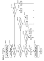
- FIG. 12 illustrates a quantization orthogonal transform coefficient of a processing target.
- a quantization orthogonal transform coefficient is referred to as a "difference coefficient.”
- a 16 ⁇ 16 difference coefficient of a processing target is partitioned into sub blocks 401 to 416 of a 4 ⁇ 4 size, and scanning is preferentially performed in units of sub blocks.
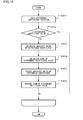
- a sub block of a processing target is decided according to a scan order that will be described later (S101).
- S101 a difference coefficient decoding process ends.
- a reference numeral 902 in FIG. 7 indicates a sub block scan order. In the present process, scanning starts from a lower rightmost sub block in a difference coefficient region, is performed according to a rule in which it proceeds from the under right to the upper left and then from the under right to the upper left, and ends at a upper leftmost sub block.
- a reference numeral 901 in FIG. 7 is a diagram illustrating a sub block scan order using arrows. When scanning is performed according to the scan order of FIG. 7 , it becomes a state in which scanning of sub blocks positioned at spatially right and lower sides among all processing target sub blocks is completed.
- step S102 a process of decoding all difference coefficient values of the processing target sub block is performed (S102). After the sub block difference coefficient values are decoded, the process proceeds to step S101.
- Significant sub block information is decoded (S201).
- the significant sub block information is a 1-bit flag indicating that there is a non-zero difference coefficient in the processing target sub block.
- the significant sub block information of 1 indicates that there is at least one non-zero difference coefficient in the processing target sub block.
- the significant sub block information of 0 indicates that all difference coefficients of the processing target sub block are 0.
- a value of the significant sub block information is determined (S202).
- the significant sub block information is 0, all the difference coefficient values of the processing target sub block are set to 0 (S209), and then the sub block difference coefficient value decoding process ends.
- the significant difference coefficient information is a 1-bit flag indicating that a difference coefficient value at a processing target position is not 0.
- the significant coefficient information of 1 indicates that a difference coefficient value at a processing target position is not 0, and the significant coefficient information of 0 indicates that a difference coefficient value at a processing target position is 0.
- the process proceeds to decoding of a difference coefficient value of step S204.
- a difference coefficient value decoding process is performed (S204). The details of the difference coefficient value decoding process will be described later.
- the difference coefficient value decoding process is completed, the process proceeds to step S101, and scanning of a next sub block is performed.
- step S203 The process of decoding the significant difference coefficient information of the sub block in step S203 will be described with reference to a flowchart of FIG. 3 .
- a processing target sub block is decided according to a certain scan order (S301).
- the scan order of difference coefficients in a sub block is assumed to follow the rule illustrated in FIG. 7 , similarly to the sub block scan order in the difference coefficient region.
- FIG. 9 illustrates an exemplary difference coefficient position for calculating the neighboring significant difference coefficient sum countCoeff.
- a reference numeral 202 indicates neighboring difference coefficients when a processing target position is a reference numeral 201
- a reference numeral 204 indicates neighboring difference coefficients when a processing target position is a reference numeral 203.
- five difference coefficients that are positioned at the right and lower sides of the processing target difference coefficient position and neighboring the processing target difference coefficient position are assumed to be neighboring difference coefficients.
- difference coefficients that belong to the same sub block as the processing target difference coefficient and are positioned at the right and lower sides of the processing target difference coefficient position are decoded coefficients.
- significant difference coefficients belonging to sub blocks at the right and lower sides of the sub block positioned at the processing target position are decoded coefficients.
- the neighboring difference coefficient sum countCoeff is a variable for estimating a probability of occurrence of a significant difference coefficient. Due to characteristics and visual characteristics of a picture, significant difference coefficients are likely to be concentrated on "1" at a low frequency range and "0" at a high frequency range.
- a difference coefficient neighboring the processing target position is set as a calculation target for the neighboring difference coefficient sum countCoeff. Neighboring difference coefficients indicating the outside of the difference coefficient region are excluded from a calculation for the neighboring significant coefficient sum countCoeff.
- the neighboring significant coefficient sum countCoeff is 0 (S303).
- a context index ctxIdx for decoding the significant difference coefficient information is set to 0 (S304), and the significant difference coefficient information is decoded using a context corresponding to the context index ctxIdx. Then, the significant difference coefficient information is set as the difference coefficient value (S308).
- the neighboring significant coefficient sum countCoeff determines whether or not the neighboring significant coefficient sum countCoeff is smaller than or equal to 2 (S305).
- the context index ctxIdx for decoding the significant difference coefficient information is set to 1 (S306), and the significant difference coefficient information is decoded using the context corresponding to the context index ctxIdx. Then, the significant difference coefficient information is set as the difference coefficient value (S308).
- the context index ctxIdx for decoding the significant difference coefficient information is set to 2 (S307), and the significant difference coefficient information is decoded using the context corresponding to the context index ctxIdx. Then, the significant difference coefficient information is set as the difference coefficient value (S308).
- a context is a variable for storing a probability of occurrence of information to be decoded, and allocation of a code word is switched based on a probability of occurrence indicated by a context.
- three contexts for coding a significant difference coefficient are defined, and a context for decoding a significant difference coefficient is decided based on the magnitude of the neighboring significant difference coefficient sum.
- the significant coefficient information has a high correlation with the neighboring significant coefficient, it is logical in terms of coding efficiency to switch a context based on the number of neighboring significant coefficient information.
- a processing target sub block is decided according to a certain scan order (S501).
- the scan order of difference coefficients in the sub block is assumed to follow the rule illustrated in FIG. 7 , similarly to the scan order of the significant difference coefficient information.
- the process of decoding the difference coefficient value is completed, and the process proceeds to a process of deciding a next sub block (S101).
- the difference coefficient value at the processing target difference coefficient position is 1, the absolute value of the difference coefficient at the processing target difference coefficient position is decoded (S503).
- the difference coefficient value is decided to be not 0, code words according to values obtained by subtracting 1 from the absolute values of the difference coefficients are coded.
- a value obtained by adding 1 to a value obtained by entropy-decoding a code word is set as the absolute value of the difference coefficient.
- a sign of the difference coefficient at the processing target difference coefficient position is decoded (S504).
- the difference coefficient value is decided based on the absolute value of the difference coefficient and the sign of the difference coefficient.
- 201 in FIG. 9 is scanned lastly in the sub block as indicated by the scan order of 902 in FIG. 7 , and its scan order is 16 as indicated in 902 in FIG. 7 . Further, among difference coefficients 202 neighboring 201, the scan order of a position neighboring below 201 is 15, and it is scanned directly before 201. Since the context index ctxIdx necessary for decoding the significant difference coefficient information of 201 is decoded based on the sum of the significant difference coefficients of 202, it is difficult to decide the context index ctxIdx of 201 until the decoding of the significant difference coefficient information of 202 is completed.
- Patent Literature 1 discloses a technique of arranging a context for a syntax element having a high frequency of occurrence on a memory having small access latency and reducing a processing delay related to decoding.
- the technique disclosed in Patent Literature 1 does not solve dependence on calculation of a context index and decoding a syntax element and is not an essential solution to a processing delay since it is difficult to perform the calculation and the decoding in parallel.
- picture coding and decoding techniques that are capable of eliminating dependence between a calculation of a context index and coding/decoding of significant difference coefficient information, performing parallel processing and implementing a context index calculating method having a small computation amount in difference coefficient coding/decoding and that are simple in a circuit configuration and suitable for real-time processing. Further, provided are picture coding and decoding techniques capable of implementing high coding efficiency by calculating a context index with reference to a neighboring difference coefficient that is appropriate in terms of a correlation.
- an embodiment of the present invention will be described.
- a "processing target block” refers to a coding target block in the case of a coding process performed by a picture coding device, and refers to a decoding target block in the case of a decoding process performed by a picture decoding device.
- a “processed block” refers to a coded block in the case of a coding process performed by a picture coding device, and refers to a decoded block in the case of a decoding process performed by a picture decoding device.
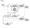
- FIG. 5 is a block diagram illustrating a configuration of a picture coding device according to an embodiment.
- the picture coding device according to the embodiment includes a subtractor 501, an orthogonal transformer/quantizer 502, an inverse quantizer/inverse transformer 503, an adder 504, a decoded picture memory 505, a predictor 506, a difference information encoder 507, a prediction information encoder 508, and a mode determiner 509.
- the mode determiner 509 tries to code all prediction candidate, and decides optimal prediction information for each block of pictures.
- the prediction information includes a partition block size, a prediction mode indicating inter prediction/intra prediction are included, motion information such as a motion vector and a reference picture index when the prediction mode is the inter prediction, and an intra prediction mode when the prediction mode is the intra prediction.
- the decided prediction information is supplied to the predictor 506 and the prediction information encoder 508.
- the prediction information encoder 508 performs variable length coding on the input prediction information, and outputs a bitstream of the prediction information.
- the predictor 506 constructs a prediction picture using the input prediction information and a decoded picture stored in the decoded picture memory 505, and supplies the constructed prediction picture to the subtractor 501.
- the subtractor 501 constructs a difference picture by subtracting the prediction picture from the original picture of the coding target, and supplies the constructed difference signal to the orthogonal transformer/quantizer 502.
- the orthogonal transformer/quantizer 502 performs orthogonal transform and quantization on the difference picture to construct a difference coefficient, and supplies the constructed difference coefficient to the inverse quantizer/inverse transformer 503 and the difference information encoder 507.
- the difference information encoder 507 performs entropy coding on the difference coefficient, and outputs the bitstream sequence of the difference information.
- the inverse quantizer/inverse transformer 503 performs inverse quantization and inverse orthogonal transform on the difference coefficient received from the orthogonal transformer/quantizer 502 to construct a decoded difference signal, and supplies the constructed decoded difference signal to the adder 504.
- the adder 504 adds the predict ion picture to the decoded difference signal to construct a decoded picture, and causes the constructed decoded picture to be stored in the decoded picture memory 505.
- FIG. 6 is a block diagram illustrating a configuration of a moving picture decoding device according to an embodiment.
- the picture decoding device according to the embodiment includes a difference information decoder 801, an inverse quantizer/inverse transformer 802, a prediction information decoder 803, an adder 804, a decoded picture memory 805, and a predictor 806.
- the respective components of the inverse quantizer/inverse transformer 802, the adder 804, the decoded picture memory 805, and the predictor 806 of FIG. 8 have functions corresponding to the respective components of the inverse quantizer/inverse transformer 503, the adder 504, the decoded picture memory 505, and the predictor 506 of the picture coding device of FIG. 5 .
- the prediction information decoder 803 performs entropy decoding on the input prediction information bitstream to construct prediction information, and supplies the constructed prediction information to the predictor 806.
- the predictor 806 constructs a prediction picture using the input prediction information and a decoded picture stored in the decoded picture memory 805, and supplies the constructed prediction picture to the adder 804.
- the difference information decoder 801 performs entropy decoding on the difference information to construct difference information.
- the constructed difference information is supplied to the inverse quantizer/inverse transformer 802.
- the inverse quantizer/inverse transformer 802 performs inverse quantization and inverse orthogonal transform on the difference information received from the difference information decoder 801 to construct the decodeddifference signal, and supplies the constructed decoded difference signal to the adder 804.
- the adder 804 adds the predict ion picture to the decoded difference signal to construct a decoded picture, and outputs the constructed decoded picture to be stored in the decoded picture memory 805.
- the difference coefficient coding and decoding processes according to the embodiment of the present invention are performed in the difference information encoder 507 of the moving picture coding device of FIG. 5 and the difference information decoder 801 of the moving the picture decoding device of FIG. 8 .
- the details of the difference information coding and decoding processes according to an embodiment will be described.
- a screen is hierarchically partitioned into rectangular blocks, and a sequential process based on a certain processing order is performed on the respective blocks.
- Each partitioned block is referred to as a "coding block.”
- a block 1817 of FIG. 14 is a maximum unit of partition in an embodiment, and referred to as a maximum coding block.
- a block 1816 of FIG. 14 is a minimum unit of partition in an embodiment, and referred to as a minimum coding block.
- the minimum coding block and the maximum coding block will be described as 4 ⁇ 4 pixels and 16 ⁇ 16 pixels.
- a prediction block has a size that is larger than or equal to the minimum coding block and smaller than or equal to the maximum coding block.
- blocks 1802, 1803, and 1804 are 16 ⁇ 16 blocks
- blocks 1805, 1810, 1811, and 1801 are 8 ⁇ 8 blocks
- blocks 1806, 1807, 1808, and 1809 are 4 ⁇ 4 blocks.
- Blocks 1812, 1813, 1814, and 1815 are non-processed blocks, and coding block sizes thereof are not decided yet.
- an optimal prediction block size is decided, and a prediction block size is coded.
- a prediction block size is derived from a bitstream. The following description will proceed in connection with an example in which a prediction block is used as a processing unit.
- a unit in which quantization and orthogonal transform are performed is identical to a unit of a prediction block, but in the coding/decoding process, it is assumed that a difference coefficient region is partitioned into a plurality of sub blocks, and scanning is performed.
- the size of a sub block is assumed to be a 4 ⁇ 4 size.
- FIG. 12 illustrates a difference coefficient region of a 16 ⁇ 16 size. 401 to 416 are sub blocks.
- a unit in which quantization and orthogonal transform are performed may be decided independently of a unit of a prediction block.
- FIG. 15 is a block diagram illustrating a detailed configuration of the difference information encoder 507 of FIG. 5 according to the first embodiment.
- the difference information encoder 507 according to the first embodiment includes an arithmetic encoder 701, a difference coefficient buffer 702, a coding controller 703, a context memory 704, and a scan controller 705, and the coding controller 703 includes a significant coefficient information coding controller 706, a difference coefficient value coding controller 707, and a significant sub block information coding controller 708.
- the scan controller 705 decides a processing target sub block (S601). When scanning of all sub blocks is completed, the difference coefficient decoding process ends.
- 902 in FIG. 7 indicates a sub block scan order. In the present process, scanning starts from a lower rightmost sub block in a difference coefficient region, is performed according to a rule of proceeding from the under right to the upper left and then from the under right to the upper left, and ends at a upper leftmost sub block.
- a context is updated through a coding process as described above.
- a reference numeral 901 of FIG. 7 is a diagram illustrating a sub block scan order using arrows.
- scanning is performed according to the scan order of FIG. 7 , it becomes a state in which scanning of sub blocks positioned at spatially right and lower sides among processing target sub blocks is completed.
- a sub block coding process is performed on the processing target sub block (S602).
- the significant sub block information coding controller 708 derives a processing target sub block from the difference coefficient buffer 702. When all difference coefficients of the sub block are scanned and all the difference coefficient values are 0, the significant sub block information is set to 0. Otherwise (when there is at least one non-zero the difference coefficient value), the significant sub block information is set to 1 (S701).
- the significant sub block information coding controller 708 decides the context index ctxIdx for coding the significant sub block information with reference to the difference coefficients included in a decoded sub block neighboring the processing target sub block from the difference coefficient buffer 702.
- the context corresponding to the context index ctxIdx is read out from the context memory 704.
- the significant sub block information and the context are transferred to the arithmetic encoder 701.
- the arithmetic encoder 701 codes the significant sub block information using the context (S702).
- the significant sub block information coding controller 708 determines a value of the significant sub block information (S703). When the significant sub block information is 0, the sub block difference coefficient value coding process ends, and then the process proceeds to step S601.
- the difference coefficient value coding controller 707 performs a process of coding all difference coefficient values of the processing target sub block (S705). The details of the process of coding the difference coefficient value of the sub block will be described later. After coding all the difference coefficient values of the sub block ends, the process proceeds to step S601.
- the significant coefficient information coding controller 706 calculates the sum of the number of non-zero difference coefficients neighboring the processing target sub block, that is, the neighboring significant coefficient sumcountCoeff (S801).
- difference coefficients that belong to sub blocks positioned at spatially right and lower sides of the processing target sub block and are neighboring the processing target sub block are defined as neighboring difference coefficients.
- FIG. 10 illustrates a neighboring difference coefficient position.
- a reference numeral 301 indicates a processing target sub block, and a reference numeral 302 indicates a neighboring difference coefficient.
- a neighboring difference coefficient indicating the outside of the difference coefficient region is excluded from a calculation of the neighboring significant coefficient sum countCoeff.
- Difference coefficients 303 belonging to sub blocks at the right and lower sides of the processing target sub block can have any of a configuration included in the neighboring difference coefficient and a configuration not included in the neighboring difference coefficient. In the configuration in which the reference numeral 303 is included in the neighboring difference coefficient, the number of neighboring difference coefficients increases, and thus a probability of occurrence of the significant difference coefficient information can be estimated with a high degree of accuracy.
- a computation amount and a circuit size can be reduced due to a reduction in an addition process related to the neighboring significant coefficient sum countCoeff and a reduction in a process of determining the boundary of the difference coefficient region.
- the significant coefficient information coding controller 706 decides the difference coefficients of the processing target (S802).
- the scan order of the difference coefficients in the sub block is assumed to follow the rule illustrated in FIG. 7 , similarly to the sub block scan order in the difference coefficient region.
- the significant difference coefficient coding process ends, and then the process proceeds to the difference coefficient value coding process (S704).
- the significant coefficient information coding controller 706 determines whether or not the neighboring significant coefficient sum countCoeff is 0 (S803).
- the processing target difference coefficient position in the processing target sub block is determined (S804) .
- Ahorizontal-direction difference coefficient position is assumed to be posX
- a vertical-direction difference coefficient position is assumed to be posY
- the context index ctxIdx for decoding the significant coefficient information is set to 2 (S815).
- a reference numeral 605 of FIG. 11 indicates a definition of the context index ctxIdx when countCoeff > 2.
- the significant coefficient information coding controller 706 derives the difference coefficient of the processing target position from the difference coefficient buffer 702. When the difference coefficient value is not 0, the significant difference coefficient information is set to 1, and otherwise (when the difference coefficient value is 0), the significant difference coefficient information is set to 0 (S816).
- the significant coefficient information coding controller 706 reads a context corresponding to the decided context index ctxIdx from the context memory 704, and transfers the significant difference coefficient information and the context to the arithmetic encoder 701.
- the arithmetic encoder 701 codes the significant difference coefficient information using the context (S817).
- the difference coefficient value coding controller 707 decides the difference coefficients of the processing target (S901).
- the scan order of the difference coefficients in the sub block is assumed to follow the rule illustrated in FIG. 7 , similarly to the scan order of the significant difference coefficients.
- the difference coefficient value coding process ends, and the process proceeds to a process of deciding a next sub block (S601).
- the difference coefficient value coding controller 707 determines whether or not the difference coefficient value at the processing target difference coefficient position is 0 (S902). When the difference coefficient value at the processing target difference coefficient position is 0, coding of the difference coefficient value at the processing target difference coefficient position is completed, and the process proceeds to step S901.
- the absolute value of the coding difference coefficient at the processing target difference coefficient position and a sign are calculated (S903 and S904).
- the coding difference coefficient absolute value is a value obtained by subtracting 1 from the absolute value of the difference coefficient. Further, when the difference coefficient is positive, the sign is set to 0, and when the difference coefficient is negative, the sign is set to 1.
- the difference coefficient value coding controller 707 reads a context from the context memory 704, and transfers the coding absolute value and the context to the arithmetic encoder 701.
- the arithmetic encoder 701 decides the coding absolute value using the context (S905).
- the difference coefficient value coding controller 707 reads a context from the context memory 704, and transfers the coding absolute value and the context to the arithmetic encoder 701.
- the arithmetic encoder 701 decides the coding absolute value using the context (S905).
- FIG. 8 is a block diagram illustrating a detailed configuration of the difference information decoder 801 of FIG. 6 according to the first embodiment.
- the difference information decoder 801 according to the first embodiment includes an arithmetic decoder 1001, a difference coefficient buffer 1002, a decoding controller 1003, a context memory 1004, and a scan controller 1005, and the decoding controller 1003 includes a significant coefficient information decoding controller 1006, a difference coefficient value decoding controller 1007, and a significant sub block information decoding controller 1008.
- the respective components of the difference coefficient buffer 1002, the context memory 1004, and the scan controller 1005 in the difference information decoder of FIG. 8 have functions corresponding to the respective components of the difference coefficient buffer 702, the context memory 704, and the scan controller 705 of FIG. 15 .
- the scan controller 1005 decides a processing target sub block (S101).
- the difference coefficient decoding process ends.
- 902 in FIG. 7 indicates a sub block scan order. In the present process, scanning starts from a lower rightmost sub block in a difference coefficient region, is performed according to a rule of proceeding from the under right to the upper left and then from the under right to the upper left, and ends at a upper leftmost sub block.
- 901 in FIG. 7 is a diagram illustrating a sub block scan order using arrows. When scanning is performed according to the scan order of FIG. 7 , it becomes a state in which scanning of sub blocks positioned at spatially right and lower sides among processing target sub blocks is completed.
- the sub block decoding process is performed on the processing target sub block (S102).
- the significant sub block information decoding controller 1008 decides a context for decoding the significant sub block information with reference to difference coefficients included in a coded sub block neighboring the processing target sub block from the difference coefficient buffer 1002, and reads the decided context from the context memory 1004.
- the context and a decoding command are transferred to the arithmetic decoder 1001.
- the arithmetic decoder 1001 performs abitstreamdecodingprocess using the context, and decodes the significant sub block information (S201).
- the significant sub block information decoding controller 1008 determines a value of the significant sub block information (S202). When the significant sub block information is 0, all the difference coefficient values of the processing target sub block of the difference coefficient buffer 1002 are set to 0 (S209), and the sub block difference coefficient value decoding process ends.
- the decoding process is performed on all significant difference coefficient information of the processing target sub block (S203). The details of the sub block significant difference coefficient information decoding process will be described later. After the decoding of all significant difference coefficient information of the sub block ends, the process proceeds to decoding of the difference coefficient value of step S204.
- step S204 The decoding process of all the difference coefficient values of the processing target sub block is performed (S204). The details of the sub block difference coefficient value decoding process will be described later. After the decoding of all the difference coefficient values of the sub block ends, the process proceeds to step S101.
- the significant coefficient information decoding controller 1006 calculates the sum countCoeff of the number of significant difference coefficients neighboring the processing target difference coefficient position (S401).
- difference coefficients belonging to sub blocks positioned at spatially right and lower sides of the processing target sub block and neighboring the processing target sub block are defined as neighboring difference coefficients.
- FIG. 10 illustrates a neighboring difference coefficient position.
- a reference numeral 301 indicates a processing target sub block, and a reference numeral 302 indicates a neighboring difference coefficient.
- a neighboring difference coefficient indicating the outside of the difference coefficient region is excluded from a calculation of the neighboring significant coefficient sum countCoeff.
- Difference coefficients 303 belonging to sub blocks at the right and lower sides of the processing target sub block can have any of a configuration included in the neighboring difference coefficient and a configuration not included in the neighboring difference coefficient. In the configuration in which the reference numeral 303 is included in the neighboring difference coefficient, the number of neighboring difference coefficients increases, and thus a probability of occurrence of the significant difference coefficient information can be estimated with a high degree of accuracy.
- a computation amount and a circuit size can be reduced due to a reduction in an addition process related to the neighboring significant coefficient sum countCoeff and a reduction in a process of determining the boundary of the difference coefficient region.
- the significant coefficient information decoding controller 1006 decides the difference coefficients of the processing target (S402).
- the scan order of the difference coefficients in the sub block is assumed to follow the rule illustrated in FIG. 7 , similarly to the sub block scan order in the difference coefficient region.
- the significant difference coefficient decoding process is completed, and then the process proceeds to the difference coefficient value decoding process (S204).
- the significant coefficient information decoding controller 1006 determines whether or not the neighboring significant coefficient sum countCoeff is 0 (S403). When the neighboring significant coefficient sum countCoeff is 0, the processing target difference coefficient position in the processing target sub block is determined (S404).
- a horizontal-direction difference coefficient position is assumed to be posX
- a vertical-direction difference coefficient position is assumed to be posY
- the context ctxIdx for decoding the significant coefficient information is set to 1 (S405), and otherwise (pos > 2)
- the context ctxIdx is set to 0 (S406).
- the context and the decoding command are transferred to the arithmetic decoder 1001.
- the arithmetic decoder 1001 performs the bitstreamdecodingprocess using the context, and decodes the significant difference coefficient information (S416).
- the context and the decoding command are transferred to the arithmetic decoder 1001.
- the arithmetic decoder 1001 performs the bitstream decoding process using the context, and decodes the significant difference coefficient information (S416).
- the context index ctxIdx for decoding the significant coefficient information is set to 2 (S415).
- a reference numeral 605 of FIG. 11 indicates a definition of the context when countCoeff > 2.
- the neighboring significant coefficient sum countCoeff When the neighboring significant coefficient sum countCoeff is large, all significant coefficient information in the processing target sub block is likely to be 1. Thus, in the above process, when the neighboring significant coefficient sum countCoeff is larger than or equal to 3, ctxIdx is set to 2 regardless of the value of pos. Further, it is also possible to break down the determination condition of the neighboring significant coefficient sum countCoeff. For example, in the case in which the neighboring significant coefficient sum countCoeff is larger than or equal to 3, the context index definition of the reference numeral 604 of FIG. 11 can be used when the neighboring significant coefficient sum countCoeff is 3, and the context index definition of the reference numeral 605 of FIG. 11 can be used when the neighboring significant coefficient sum countCoeff is larger than or equal to 4. Through this configuration, it is possible to improve neighboring information correlation use efficiency and coding efficiency.
- orthogonal transform coefficients of a picture are likely to be concentrated on low frequency components, and the significant coefficient information is likely to be 1. Further, since the high frequency component of the orthogonal transform coefficient is hardly visually affected and often coarsely quantized, the coefficient value of the high frequency component becomes 0, and the significant coefficient information of the high frequency component is likely to be 0. This feature is not limited to the entire difference coefficient region and similarly applies to each sub block without, and the significant coefficient information of components of a sub block at a low frequency range side is more likely to be 1 than that of components of the same sub block at a high frequency range side.
- the estimation accuracy of the probability of occurrence of the significant coefficient information is improved. Further, in the high frequency range in which the significant difference coefficient is likely to be 0, the neighboring significant coefficient sum is also small, and in the low frequency range in which the significant difference coefficient is likely to be 1, the neighboring significant coefficient sum strongly tends to be large, and when the neighboring significant coefficient sum is used as an index indicating how much the target sub block includes the significant difference coefficient information, the estimation accuracy of the probability of occurrence of the significant coefficient information is improved.
- the present process it is possible to calculate the context indices of all coefficient positions in the sub block by calculating the neighboring significant difference coefficient sum for the sub block only once. Compared to the method of individually calculating the neighboring significant difference coefficient sum at each coefficient position, it is possible to reduce the computation amount of the neighboring significant difference coefficient sum. Further, in the configuration of using a decoding result of an immediately previous significant difference coefficient in the scan order for a calculation of the context index, it is necessary to sequentially perform a calculation of the context index in the sub block and decoding of the significant difference coefficient.
- the neighboring significant difference coefficient sum and the processing target coefficient position are referred to for a calculation of the context index, but since the difference coefficients belonging to the processing target sub block are not used for the neighboring significant difference coefficient sum, there is no dependence relation between sub blocks in the calculation of the context index. Since it is possible to calculate the context indices for all the significant difference coefficients at the beginning of the sub block, it is possible to perform the calculation of the context index and the decoding process of the significant difference coefficient information in parallel. It is possible to reduce the processing delay related to decoding of the significant coefficient information that is high in the frequency of occurrence in the bitstream.
- the neighboring significant coefficient it is possible to calculate the context with reference to the significant sub block information.
- a configuration of using the sum of significant sub block information of a neighboring sub block at the right side of a processing target sub block and significant sub block information of a neighboring sub block at the lower side of the processing target sub block can reduce the computation amount and the circuit size compared to the above-described configuration.
- FIG. 20 illustrates an example in which the difference coefficient region is divided into two regions of a low frequency region and a high frequency region.
- reference numerals 1101, 1102, 1103, 1104, 1105, and 1109 indicate low frequency components
- reference numerals 1106, 1107, 1108, 1110, 1111, 1112, 1113, 1114, 1115, and 1116 indicate high frequency regions.
- the context index the sum of neighboring coefficient absolute values using the neighboring coefficient absolute values instead of the neighboring significant difference coefficient sum. Since the difference coefficient absolute value of the low frequency component is commonly large, when the sum of neighboring difference coefficient absolute values is large, it is possible to improve the coding efficiency by setting the context so that the probability of occurrence of the significant difference coefficient information is high.
- the prediction mode used to calculate the difference coefficient it is possible to improve the context estimation accuracy by adding the prediction mode used to calculate the difference coefficient to a condition determination in the process of calculating the context index of the significant difference coefficient. It is because of a feature difference in which commonly, compared to the intra prediction in which only a decoded region of a decoding target picture is used as a reference target, the inter prediction in which it is possible to refer to a plurality of decoded pictures is high in the prediction accuracy and a difference hardly occurs.
- the significant coefficient information decoding controller 1006 decides the difference coefficients of the processing target (S501).
- the scan order of the difference coefficients in the sub block is assumed to follow the rule illustrated in FIG. 7 , similarly to the scan order of the significant difference coefficients.
- the difference coefficient value decoding process is completed, and the process proceeds to a process of deciding a next sub block (S101).
- the significant coefficient information decoding controller 1006 determines whether or not the difference coefficient value at the processing target difference coefficient position is 0 (S502). When the difference coefficient value at the processing target difference coefficient position is 0, decoding of the difference coefficient value at the processing target difference coefficient position is completed, and the process proceeds to step S501.
- the difference coefficient value at the processing target difference coefficient position is 1, the absolute value of the difference coefficient at the processing target difference coefficient position is decoded (S503).
- the difference coefficient value is decided to be not 0, and code words according to values obtained by subtracting 1 from the absolute values of the difference coefficients are decoded as a bitstream.
- a value obtained by adding 1 to a value obtained by entropy-decoding a code word is set as the absolute value of the difference coefficient.
- the sign of the difference coefficient at the processing target difference coefficient position is decoded (S504).
- the difference coefficient value is decided based on the absolute value of the difference coefficient and the sign of the difference coefficient.
- the context index for decoding the significant difference coefficient information is calculated based on the significant difference coefficient information of the decoded sub block, but a similar process can be applied to a calculation of the context index of the difference coefficient value. Since the difference coefficient value has a correlation with the neighboring coefficient value and has a feature of being concentrated on the low frequency component similarly to the significant difference coefficient information, the difference coefficient value can be efficiently coded by setting a context index indicating that a probability of occurrence of a large difference coefficient value is high when the neighboring significant difference coefficient sum or the neighboring difference coefficient absolute value sum is large and setting a context index indicating that a probability of occurrence of a small difference coefficient value is high when the neighboring significant difference coefficient sum or the neighboring difference coefficient absolute value sum is small.
- the picture coding device and the picture decoding device according to the first embodiment have the following effects.
- a bitstream of a picture output from the picture coding device has a specific data format that can be decoded according to a coding technique used in the embodiment, and the picture decoding device corresponding to the picture coding device can decode the bitstream of the specific data format.
- a bitstream may be converted to have a data format suitable for a transmission form of a transmission path and then transmitted.
- a picture transmitting device that converts the bitstream output from the picture coding device into coding data of the data format suitable for the transmission form of the communication path and then transmits the coding data to the network and a picture receiving device that receives the coding data from the network, reconstructs the bitstream, and supplies the bitstream to the picture decoding device are provided.
- the picture transmitting device includes a memory that buffers the bitstream output from the picture coding device, a packet processor that packetizes the bitstream, and a transmitter that transmits the packetized coding data via the network.
- the picture receiving device includes a receiver that receives the packetized coding data via the network, a memory that buffers the received coding data, and a packet processor that performs packet processing on the coding data, constructs the bitstream, and supplies the bitstream to the picture decoding device.
- the process related to the coding and the decoding can be implemented as a transmitting, accumulating, or receiving device using hardware and can be implemented by firmware stored in read only memory (ROM), flash memory, or the like or computer software or the like.
- the firmware program and the software program can be recorded in a computer readable recording medium and provided, can be provided from a server via a wired or wireless network, or can be provided as data broadcasting of a terrestrial or satellite digital broadcasting.
- the present invention can be used for entropy coding and decoding techniques for a residual signal.
Abstract
Description
- The present invention relates to picture coding and decoding technique, and more particularly, to entropy coding and decoding techniques of residual signals.
- In MPEG-4 AVC as an international standard for moving picture coding, context-adaptive binary arithmetic coding called CABAC is employed as an entropy coding scheme. In the CABAC, a plurality of variables called a context for storing a probability of occurrence of information to be coded are used. An optimal context is selected from neighboring coding information and used for coding. Since a probability of occurrence is updated by a coding process in each context, it is possible to estimate a probability of occurrence of coding information with a high degree of accuracy and perform efficient coding.
- Patent Literature 1:
JP 2007-300517 A - In MPEG-4 AVC, as a context is switched based on decoded neighboring information, learning of a probability of occurrence based on a decoding result is performed in addition to estimation of a probability of occurrence of information. It is possible to optimize a probability of occurrence of information to be decoded for each context, and thus coding efficiency is improved. However, it is necessary to sequentially process a calculation of a context index and decoding of significant difference coefficient information for all significant difference coefficient information in a processing target block, and thus it takes a time to calculate.
-
Patent Literature 1 discloses a technique of arranging a context for a syntax element having a high frequency of occurrence on a memory having small access latency and reducing a processing delay related to decoding. However, the technique disclosed inPatent Literature 1 does not solve dependence of a calculation of a context index and decoding a syntax element and is not an essential solution to a processing delay since it is difficult to perform the calculation and the decoding in parallel. - The present invention was made in light of the foregoing, and it is an object of the present invention to provide picture coding and decoding techniques that are capable of performing parallel processing and thus implementing a context index calculating method having a small computation amount in difference coefficient coding/decoding and that are simple in a circuit configuration and suitable for real-time processing. It is another object of the present invention to provide picture coding and decoding techniques capable of implementing high coding efficiency by calculating a context index with reference to a neighboring difference coefficient that is appropriate in terms of a correlation.
- In order to solve the problem, a picture coding device according to one embodiment of the present invention is a picture coding device that partitions difference information between a picture serving as a coding target and a picture serving as a prediction target into a plurality of sub blocks, and codes the partitioned sub block in a certain order, the picture coding device includes: a significant sub block information encoder (706, 708, 701) that codes significant sub block information indicating whether or not all values of difference coefficients belonging to the sub block are zero; a significant difference coefficient information encoder (706, 708) that codes significant difference coefficient information indicating whether or not the value of the difference coefficient is zero; a difference coefficient value encoder (707, 701) that codes the value of the difference coefficient; and a context deriver (707, 701) that derives a context for coding the significant difference coefficient information of the sub block serving as the coding target based on at least one of the significant sub block information, the significant difference coefficient information, and the value of the difference coefficient of the coded sub block neighboring the sub block serving as the coding target.
- Another embodiment of the present invention provides a picture coding method. This method is a picture coding method of partitioning difference information between a picture serving as a coding target and a picture serving as a prediction target into a plurality of sub blocks, and codes the partitioned sub block in a certain order, and includes: coding significant sub block information indicating whether or not all values of difference coefficients belonging to the sub block are zero; coding significant difference coefficient information indicating whether or not the value of the difference coefficient is zero; coding the value of the difference coefficient; and deriving a context for coding the significant difference coefficient information of the sub block serving as the coding target based on at least one of the significant sub block information, the significant difference coefficient information, and the value of the difference coefficient of the coded sub block neighboring the sub block serving as the coding target.
- Further, another embodiment of the present invention provides a transmitting device. This device includes: a packet processor that packetizes a bitstream coded by a picture coding method of partitioning difference information between a picture serving as a coding target and a picture serving as a prediction target into a plurality of sub blocks, and codes the partitioned sub block in a certain order, and obtain coding data; and a transmitter that transmits the packetized coding data. The picture coding method includes: coding significant sub block information indicating whether or not all values of difference coefficients belonging to the sub block are zero; coding significant difference coefficient information indicating whether or not the value of the difference coefficient is zero; coding the value of the difference coefficient; and deriving a context for coding the significant difference coefficient information of the sub block serving as the coding target based on at least one of the significant sub block information, the significant difference coefficient information, and the value of the difference coefficient of the coded sub block neighboring the sub block serving as the coding target.
- Further, another embodiment of the present invention provides a transmission method. This method includes: packetizing a bitstream coded by a picture coding method of partitioning difference information between a picture serving as a coding target and a picture serving as a prediction target into a plurality of sub blocks, and codes the partitioned sub block in a certain order, and obtaining coding data; and transmitting the packetized coding data. The picture coding method includes: coding significant sub block information indicating whether or not all values of difference coefficients belonging to the sub block are zero; coding significant difference coefficient information indicating whether or not the value of the difference coefficient is zero; coding the value of the difference coefficient; and deriving a context for coding the significant difference coefficient information of the sub block serving as the coding target based on at least one of the significant sub block information, the significant difference coefficient information, and the value of the difference coefficient of the coded sub block neighboring the sub block serving as the coding target.
- A picture decoding device according an embodiment of the present invention is a picture decoding device that decodes a bitstream obtained by partitioning difference information between a picture serving as a decoding target and a picture serving as a prediction target into a plurality of sub blocks and coding the partitioned sub block in a certain order, and includes: a significant sub block information decoder (1006, 1008, 1001) that decodes significant sub block information indicating whether or not all values of difference coefficients belonging to the sub block are zero; a significant difference coefficient information decoder (1006, 1008) that decodes significant difference coefficient information indicating whether or not the value of the difference coefficient is zero; a difference coefficient value decoder (1007, 1001) that decodes the value of the difference coefficient; and a context deriver (1007, 1001) that derives a context for decoding the significant difference coefficient information of the sub block serving as the decoding target based on at least one of the significant sub block information, the significant difference coefficient information, and the value of the difference coefficient of the decoded sub block neighboring the sub block serving as the decoding target.
- Another embodiment of the present invention provides a picture decoding method. This method is a picture decoding method that decodes a bitstream obtained by partitioning difference information between a picture serving as a decoding target and a picture serving as a prediction target into a plurality of sub blocks and coding the partitioned sub block in a certain order, and includes: decoding significant sub block information indicating whether or not all values of difference coefficients belonging to the sub block are zero; decoding significant difference coefficient information indicating whether or not the value of the difference coefficient is zero; decoding the value of the difference coefficient; and deriving a context for decoding the significant difference coefficient information of the sub block serving as the decoding target based on at least one of the significant sub block information, the significant difference coefficient information, and the value of the difference coefficient of the decoded sub block neighboring the sub block serving as the decoding target.
- Further, another embodiment of the present invention provides a receiving device. This device is a receiving device that receives a bitstream obtained by coding a moving picture and decodes the received bitstream, and includes: a receiver that receives coding data obtained by packetizing a bitstream obtained by partitioning difference information between a picture serving as a decoding target and a picture serving as a prediction target into a plurality of sub blocks and coding the partitioned sub block in a certain order; a reconstructor that performs packet processing on the received packetized coding data to reconstruct the bitstream; a significant subblock information decoder (1006, 1008, 1001) that decodes significant sub block information indicating whether or not all values of difference coefficients belonging to the sub block are zero from the reconstructed bitstream; a significant difference coefficient information decoder (1006, 1008) that decodes significant difference coefficient information indicating whether or not the value of the difference coefficient is zero from the reconstructed bitstream; a difference coefficient value decoder (1007, 1001) that decodes the value of the difference coefficient from the reconstructed bit stream; and a context deriver (1007, 1001) that derives a context for decoding the significant difference coefficient information of the sub block serving as the decoding target based on at least one of the significant sub block information, the significant difference coefficient information, and the value of the difference coefficient of the decoded sub block neighboring the sub block serving as the decoding target.
- Further, another embodiment of the present invention provides a reception method. This method is a reception method of receiving a bitstream obtained by coding a moving picture and decoding the received bitstream, and includes: receiving coding data obtained by packetizing a bitstream obtained by partitioning difference information between a picture serving as a decoding target and a picture serving as a prediction target into a plurality of sub blocks and coding the partitioned sub block in a certain order; performing packet processing on the received packetized coding data to reconstruct the bitstream; decoding significant sub block information indicating whether or not all values of difference coefficients belonging to the sub block are zero from the reconstructed bitstream; decoding significant difference coefficient information indicating whether or not the value of the difference coefficient is zero from the reconstructed bitstream; decoding the value of the difference coefficient from the reconstructed bitstream, and deriving a context for decoding the significant difference coefficient information of the sub block serving as the decoding target based on at least one of the significant sub block information, the significant difference coefficient information, and the value of the difference coefficient of the decoded sub block neighboring the sub block serving as the decoding target.
- Further, an embodiment obtained by exchanging an arbitrary combination of the above components and an expression of the present invention among a method, a device, a system, a recording medium, a computer program, and the like is also effective as an aspect of the present invention.
- According to the present invention, it is possible to implement coding and decoding of a difference signal suitable for real-time processing through a simple circuit configuration.
-
-
FIG. 1 is a flowchart for describing a difference coefficient decoding process according to a related art; -
FIG. 2 is a flowchart for describing a sub block difference coefficient decoding process according to a related art; -
FIG. 3 is a flowchart for describing a significant difference coefficient decoding process according to a related art; -
FIG. 4 is a flowchart for describing a difference coefficient value decoding process according to a related art; -
FIG. 5 is a block diagram illustrating a configuration of a picture coding device that performs a difference coefficient coding method according to an embodiment; -
FIG. 6 is a block diagram illustrating a configuration of a picture decoding device that performs a difference coefficient decoding method according to the embodiment; -
FIG. 7 is a diagram for describing a scan order of difference coefficients of a sub block; -
FIG. 8 is a block diagram illustrating a detailed configuration of the picture decoding device ofFIG. 6 according to a first embodiment; -
FIG. 9 is a diagram for describing a definition of a neighboring difference coefficient in the significant difference coefficient decoding process ofFIG. 3 ; -
FIG. 10 is a diagram for describing a definition of a neighboring difference coefficient in a significant difference coefficient decoding process ofFIG. 13 ; -
FIG. 11 is a diagram for describing a definition of a context in the significant difference coefficient decoding process ofFIG. 4 ; -
FIG. 12 is a diagram for describing sub block partitioning of a difference coefficient; -
FIG. 13 is a flowchart for describing a difference coefficient value decoding process according to the first embodiment; -
FIG. 14 is a diagram for describing a coding block size; -
FIG. 15 is a block diagram illustrating a detailed configuration of the picture coding device ofFIG. 5 according to the first embodiment; -
FIG. 16 is a flowchart for describing a difference coefficient coding process according to the first embodiment; -
FIG. 17 is a flowchart for describing a sub block difference coefficient coding process according to the first embodiment; -
FIG. 18 is a flowchart for describing a significant difference coefficient coding process according to the first embodiment; -
FIG. 19 is a flowchart for describing a difference coefficient value codingprocess according to the first embodiment; and -
FIG. 20 is a diagram for describing a configuration of using a sub block position for a calculation of a context of significant difference coefficient information. - A technique as the premise of an embodiment of the present invention will be first described.
- A technique of associating each coding syntax with a plurality of contexts and selecting a context based on a correlation of a syntax element can optimize code allocation and thus can be efficient coding.
- As exemplary context adaptive entropy coding, a process of decoding a quantization orthogonal transform coefficient of a difference signal to be coded in a 16 × 16 size will be described with reference to a flowchart of
FIG. 1 .FIG. 12 illustrates a quantization orthogonal transform coefficient of a processing target. Hereinafter, a quantization orthogonal transform coefficient is referred to as a "difference coefficient." In the present process, a 16 × 16 difference coefficient of a processing target is partitioned intosub blocks 401 to 416 of a 4 × 4 size, and scanning is preferentially performed in units of sub blocks. - A sub block of a processing target is decided according to a scan order that will be described later (S101). When scanning of all sub blocks ends, a difference coefficient decoding process ends. A
reference numeral 902 inFIG. 7 indicates a sub block scan order. In the present process, scanning starts from a lower rightmost sub block in a difference coefficient region, is performed according to a rule in which it proceeds from the under right to the upper left and then from the under right to the upper left, and ends at a upper leftmost sub block. Areference numeral 901 inFIG. 7 is a diagram illustrating a sub block scan order using arrows. When scanning is performed according to the scan order ofFIG. 7 , it becomes a state in which scanning of sub blocks positioned at spatially right and lower sides among all processing target sub blocks is completed. - Referring back to the flowchart of
FIG. 1 , a process of decoding all difference coefficient values of the processing target sub block is performed (S102). After the sub block difference coefficient values are decoded, the process proceeds to step S101. - The details of the sub block difference coefficient value decoding process will be described with reference to the flowchart of
FIG. 2 . - Significant sub block information is decoded (S201). The significant sub block information is a 1-bit flag indicating that there is a non-zero difference coefficient in the processing target sub block. The significant sub block information of 1 indicates that there is at least one non-zero difference coefficient in the processing target sub block. The significant sub block information of 0 indicates that all difference coefficients of the processing target sub block are 0.
- A value of the significant sub block information is determined (S202). When the significant sub block information is 0, all the difference coefficient values of the processing target sub block are set to 0 (S209), and then the sub block difference coefficient value decoding process ends.
- When the significant sub block information is 1, a process of decoding all significant difference coefficient information of the processing target sub block is performed (S203). The significant difference coefficient information is a 1-bit flag indicating that a difference coefficient value at a processing target position is not 0. The significant coefficient information of 1 indicates that a difference coefficient value at a processing target position is not 0, and the significant coefficient information of 0 indicates that a difference coefficient value at a processing target position is 0. The details of the process of decoding the significant difference coefficient information of the sub block will be described later. After all significant difference coefficient information of the sub block is decoded, the process proceeds to decoding of a difference coefficient value of step S204.
- A difference coefficient value decoding process is performed (S204). The details of the difference coefficient value decoding process will be described later. The difference coefficient value decoding process is completed, the process proceeds to step S101, and scanning of a next sub block is performed.
- The process of decoding the significant difference coefficient information of the sub block in step S203 will be described with reference to a flowchart of
FIG. 3 . - A processing target sub block is decided according to a certain scan order (S301). The scan order of difference coefficients in a sub block is assumed to follow the rule illustrated in
FIG. 7 , similarly to the sub block scan order in the difference coefficient region. - A neighboring significant difference coefficient sum countCoeff that is a sum of the number of non-zero difference coefficients that neighbor a processing target difference coefficient position and are decoded is calculated (S302).
FIG. 9 illustrates an exemplary difference coefficient position for calculating the neighboring significant difference coefficient sum countCoeff. Areference numeral 202 indicates neighboring difference coefficients when a processing target position is areference numeral 201, and areference numeral 204 indicates neighboring difference coefficients when a processing target position is areference numeral 203. As illustrated inFIG. 9 , five difference coefficients that are positioned at the right and lower sides of the processing target difference coefficient position and neighboring the processing target difference coefficient position are assumed to be neighboring difference coefficients. Since the scan order of the difference coefficients follows the rule ofFIG. 7 , difference coefficients that belong to the same sub block as the processing target difference coefficient and are positioned at the right and lower sides of the processing target difference coefficient position are decoded coefficients. Similarly, significant difference coefficients belonging to sub blocks at the right and lower sides of the sub block positioned at the processing target position are decoded coefficients. The neighboring difference coefficient sum countCoeff is a variable for estimating a probability of occurrence of a significant difference coefficient. Due to characteristics and visual characteristics of a picture, significant difference coefficients are likely to be concentrated on "1" at a low frequency range and "0" at a high frequency range. Since a significant difference coefficient has a spatial correlation, a difference coefficient neighboring the processing target position is set as a calculation target for the neighboring difference coefficient sum countCoeff. Neighboring difference coefficients indicating the outside of the difference coefficient region are excluded from a calculation for the neighboring significant coefficient sum countCoeff. - Referring back to the flowchart of
FIG. 3 , it is determined whether or not the neighboring significant coefficient sum countCoeff is 0 (S303). When the neighboring significant coefficient sum countCoeff is 0, a context index ctxIdx for decoding the significant difference coefficient information is set to 0 (S304), and the significant difference coefficient information is decoded using a context corresponding to the context index ctxIdx. Then, the significant difference coefficient information is set as the difference coefficient value (S308). - When the neighboring significant coefficient sum countCoeff is not 0, determines whether or not the neighboring significant coefficient sum countCoeff is smaller than or equal to 2 (S305). When the neighboring significant coefficient sum countCoeff is smaller than or equal to 2, the context index ctxIdx for decoding the significant difference coefficient information is set to 1 (S306), and the significant difference coefficient information is decoded using the context corresponding to the context index ctxIdx. Then, the significant difference coefficient information is set as the difference coefficient value (S308).
- When the neighboring significant coefficient sum countCoeff is neither smaller than nor equal to 2, that is, when the neighboring significant coefficient sum countCoeff is larger than or equal to 3, the context index ctxIdx for decoding the significant difference coefficient information is set to 2 (S307), and the significant difference coefficient information is decoded using the context corresponding to the context index ctxIdx. Then, the significant difference coefficient information is set as the difference coefficient value (S308).
- A context is a variable for storing a probability of occurrence of information to be decoded, and allocation of a code word is switched based on a probability of occurrence indicated by a context. In the above example, three contexts for coding a significant difference coefficient are defined, and a context for decoding a significant difference coefficient is decided based on the magnitude of the neighboring significant difference coefficient sum. In advance, a high probability of occurrence of the significant coefficient information of 0 is set to a context corresponding to the context index ctxIdx (= 0) when the neighboring significant coefficient sum countCoeff is 0, and a high probability of occurrence of the significant coefficient information of 1 is set to a context corresponding to the context index ctxIdx (= 2) when the neighboring significant coefficient sum countCoeff is larger than or equal to 3. Since it is possible to reduce a coding amount for information having a high probability of occurrence, the coding efficiency can be improved by increasing the estimation accuracy of the probability of occurrence.
- In MPEG-4 AVC, learning of a probability of occurrence based on a decoding result is performed in addition to estimation of a probability of occurrence of information by switching of a context based on decoded neighboring information. It is possible to optimize aprobability of occurrence of information to be decoded for each context, and thus the coding efficiency is improved.
- Commonly, information of an orthogonal transform component of a picture is likely to be concentrated at a low frequency range. Further, since visual characteristics have little influence on degradation of a high frequency component, coarse quantization of a high frequency component is often practically performed. Thus, the significant coefficient information tends to be concentrated on the low frequency component. The significant coefficient information has a high correlation with the neighboring significant coefficient, it is logical in terms of coding efficiency to switch a context based on the number of neighboring significant coefficient information.
- [Difference coefficient value decoding process] The process of decoding difference coefficient values of a sub block in step S204 in the flowchart of
FIG. 2 will be described with reference to a flowchart ofFIG. 13 . - A processing target sub block is decided according to a certain scan order (S501). The scan order of difference coefficients in the sub block is assumed to follow the rule illustrated in
FIG. 7 , similarly to the scan order of the significant difference coefficient information. When scanning of all the difference coefficients of the sub block ends, the process of decoding the difference coefficient value is completed, and the process proceeds to a process of deciding a next sub block (S101). - It is determined whether or not the difference coefficient value at the processing target difference coefficient position is 0 (S502). When the difference coefficient value at the processing target difference coefficient position is 0, decoding of the difference coefficient value at the processing target difference coefficient position is completed, and the process proceeds to step S501.
- When the difference coefficient value at the processing target difference coefficient position is 1, the absolute value of the difference coefficient at the processing target difference coefficient position is decoded (S503). When the present process is performed, the difference coefficient value is decided to be not 0, code words according to values obtained by subtracting 1 from the absolute values of the difference coefficients are coded. Thus, a value obtained by adding 1 to a value obtained by entropy-decoding a code word is set as the absolute value of the difference coefficient.
- A sign of the difference coefficient at the processing target difference coefficient position is decoded (S504). The difference coefficient value is decided based on the absolute value of the difference coefficient and the sign of the difference coefficient.
- In the significant difference coefficient information decoding process, 201 in
FIG. 9 is scanned lastly in the sub block as indicated by the scan order of 902 inFIG. 7 , and its scan order is 16 as indicated in 902 inFIG. 7 . Further, amongdifference coefficients 202 neighboring 201, the scan order of a position neighboring below 201 is 15, and it is scanned directly before 201. Since the context index ctxIdx necessary for decoding the significant difference coefficient information of 201 is decoded based on the sum of the significant difference coefficients of 202, it is difficult to decide the context index ctxIdx of 201 until the decoding of the significant difference coefficient information of 202 is completed. It means that it is necessary to sequentially process a calculation of ctxIdx and decoding the significant difference coefficient information for all significant difference coefficient information in the sub block, and thus it is difficult to reduce time complexity by parallelization. Meanwhile, an occupancy ratio of the difference coefficient on a bitstream is high, and the context index calculation process and the decoding process of the significant difference coefficient information are large in their occupied time complexity in the entire decoding process. In other words, the decoding process of the significant coefficient information hits a maximum bottleneck in the real-time decoding process. -
Patent Literature 1 discloses a technique of arranging a context for a syntax element having a high frequency of occurrence on a memory having small access latency and reducing a processing delay related to decoding. However, the technique disclosed inPatent Literature 1 does not solve dependence on calculation of a context index and decoding a syntax element and is not an essential solution to a processing delay since it is difficult to perform the calculation and the decoding in parallel. - In this regard, according to an embodiment of the present invention, provided are picture coding and decoding techniques that are capable of eliminating dependence between a calculation of a context index and coding/decoding of significant difference coefficient information, performing parallel processing and implementing a context index calculating method having a small computation amount in difference coefficient coding/decoding and that are simple in a circuit configuration and suitable for real-time processing. Further, provided are picture coding and decoding techniques capable of implementing high coding efficiency by calculating a context index with reference to a neighboring difference coefficient that is appropriate in terms of a correlation. Hereinafter, an embodiment of the present invention will be described.
- In the following description, a "processing target block" refers to a coding target block in the case of a coding process performed by a picture coding device, and refers to a decoding target block in the case of a decoding process performed by a picture decoding device. A "processed block" refers to a coded block in the case of a coding process performed by a picture coding device, and refers to a decoded block in the case of a decoding process performed by a picture decoding device. Hereinafter, these meanings are used unless otherwise described.
- An exemplary picture coding device according to the present invention will be described with reference to the appended drawings.
-
FIG. 5 is a block diagram illustrating a configuration of a picture coding device according to an embodiment. The picture coding device according to the embodiment includes asubtractor 501, an orthogonal transformer/quantizer 502, an inverse quantizer/inverse transformer 503, anadder 504, a decodedpicture memory 505, apredictor 506, adifference information encoder 507, aprediction information encoder 508, and amode determiner 509. - The
mode determiner 509 tries to code all prediction candidate, and decides optimal prediction information for each block of pictures. The prediction information includes a partition block size, a prediction mode indicating inter prediction/intra prediction are included, motion information such as a motion vector and a reference picture index when the prediction mode is the inter prediction, and an intra prediction mode when the prediction mode is the intra prediction. The decided prediction information is supplied to thepredictor 506 and theprediction information encoder 508. - The
prediction information encoder 508 performs variable length coding on the input prediction information, and outputs a bitstream of the prediction information. - The
predictor 506 constructs a prediction picture using the input prediction information and a decoded picture stored in the decodedpicture memory 505, and supplies the constructed prediction picture to thesubtractor 501. - The
subtractor 501 constructs a difference picture by subtracting the prediction picture from the original picture of the coding target, and supplies the constructed difference signal to the orthogonal transformer/quantizer 502. - The orthogonal transformer/
quantizer 502 performs orthogonal transform and quantization on the difference picture to construct a difference coefficient, and supplies the constructed difference coefficient to the inverse quantizer/inverse transformer 503 and thedifference information encoder 507. - The
difference information encoder 507 performs entropy coding on the difference coefficient, and outputs the bitstream sequence of the difference information. - The inverse quantizer/
inverse transformer 503 performs inverse quantization and inverse orthogonal transform on the difference coefficient received from the orthogonal transformer/quantizer 502 to construct a decoded difference signal, and supplies the constructed decoded difference signal to theadder 504. - The
adder 504 adds the predict ion picture to the decoded difference signal to construct a decoded picture, and causes the constructed decoded picture to be stored in the decodedpicture memory 505. - An exemplary picture decoding device according to the present invention will be described with reference to the appended drawings.
-
FIG. 6 is a block diagram illustrating a configuration of a moving picture decoding device according to an embodiment. The picture decoding device according to the embodiment includes adifference information decoder 801, an inverse quantizer/inverse transformer 802, aprediction information decoder 803, anadder 804, a decodedpicture memory 805, and apredictor 806. - Since the decoding process of the picture decoding device of
FIG. 6 corresponds to the decoding process provided in the picture coding device ofFIG. 5 , the respective components of the inverse quantizer/inverse transformer 802, theadder 804, the decodedpicture memory 805, and thepredictor 806 ofFIG. 8 have functions corresponding to the respective components of the inverse quantizer/inverse transformer 503, theadder 504, the decodedpicture memory 505, and thepredictor 506 of the picture coding device ofFIG. 5 . - The
prediction information decoder 803 performs entropy decoding on the input prediction information bitstream to construct prediction information, and supplies the constructed prediction information to thepredictor 806. - The
predictor 806 constructs a prediction picture using the input prediction information and a decoded picture stored in the decodedpicture memory 805, and supplies the constructed prediction picture to theadder 804. - The
difference information decoder 801 performs entropy decoding on the difference information to construct difference information. The constructed difference information is supplied to the inverse quantizer/inverse transformer 802. - The inverse quantizer/
inverse transformer 802 performs inverse quantization and inverse orthogonal transform on the difference information received from thedifference information decoder 801 to construct the decodeddifference signal, and supplies the constructed decoded difference signal to theadder 804. - The
adder 804 adds the predict ion picture to the decoded difference signal to construct a decoded picture, and outputs the constructed decoded picture to be stored in the decodedpicture memory 805. - The difference coefficient coding and decoding processes according to the embodiment of the present invention are performed in the
difference information encoder 507 of the moving picture coding device ofFIG. 5 and thedifference information decoder 801 of the moving the picture decoding device ofFIG. 8 . Next, the details of the difference information coding and decoding processes according to an embodiment will be described. - In the embodiment, as illustrated in
FIG. 14 , a screen is hierarchically partitioned into rectangular blocks, and a sequential process based on a certain processing order is performed on the respective blocks. Each partitioned block is referred to as a "coding block." Ablock 1817 ofFIG. 14 is a maximum unit of partition in an embodiment, and referred to as a maximum coding block. Ablock 1816 ofFIG. 14 is a minimum unit of partition in an embodiment, and referred to as a minimum coding block. Hereinafter, the minimum coding block and the maximum coding block will be described as 4 × 4 pixels and 16 × 16 pixels. - Among coding blocks, a unit in which intra prediction is performed is referred to as a prediction block. A prediction block has a size that is larger than or equal to the minimum coding block and smaller than or equal to the maximum coding block. In
FIG. 14 , blocks 1802, 1803, and 1804 are 16 × 16 blocks, blocks 1805, 1810, 1811, and 1801 are 8 × 8 blocks, and blocks 1806, 1807, 1808, and 1809 are 4 × 4 blocks.Blocks - A unit in which quantization and orthogonal transform are performed is identical to a unit of a prediction block, but in the coding/decoding process, it is assumed that a difference coefficient region is partitioned into a plurality of sub blocks, and scanning is performed. The size of a sub block is assumed to be a 4 × 4 size.
FIG. 12 illustrates a difference coefficient region of a 16 × 16 size. 401 to 416 are sub blocks. Here, a unit in which quantization and orthogonal transform are performed may be decided independently of a unit of a prediction block. - A first embodiment of a difference information coding method according to an embodiment of the present invention will be described.
FIG. 15 is a block diagram illustrating a detailed configuration of thedifference information encoder 507 ofFIG. 5 according to the first embodiment. Thedifference information encoder 507 according to the first embodiment includes anarithmetic encoder 701, adifference coefficient buffer 702, acoding controller 703, acontext memory 704, and ascan controller 705, and thecoding controller 703 includes a significant coefficientinformation coding controller 706, a difference coefficientvalue coding controller 707, and a significant sub blockinformation coding controller 708. - Next, the difference coefficient coding process will be described with reference to flowcharts of
FIGS. 16 ,17 ,18 , and19 . - The
scan controller 705 decides a processing target sub block (S601). When scanning of all sub blocks is completed, the difference coefficient decoding process ends. 902 inFIG. 7 indicates a sub block scan order. In the present process, scanning starts from a lower rightmost sub block in a difference coefficient region, is performed according to a rule of proceeding from the under right to the upper left and then from the under right to the upper left, and ends at a upper leftmost sub block. A context is updated through a coding process as described above. When the scan order is applied, there is a processing advantage of improving an estimation accuracy of a probability of occurrence of a difference coefficient of a frequency component by performing coding of a low frequency component in which a difference coefficient is likely to occur after coding of a high frequency component. Areference numeral 901 ofFIG. 7 is a diagram illustrating a sub block scan order using arrows. When scanning is performed according to the scan order ofFIG. 7 , it becomes a state in which scanning of sub blocks positioned at spatially right and lower sides among processing target sub blocks is completed. A sub block coding process is performed on the processing target sub block (S602). - The significant sub block
information coding controller 708 derives a processing target sub block from thedifference coefficient buffer 702. When all difference coefficients of the sub block are scanned and all the difference coefficient values are 0, the significant sub block information is set to 0. Otherwise (when there is at least one non-zero the difference coefficient value), the significant sub block information is set to 1 (S701). - The significant sub block
information coding controller 708 decides the context index ctxIdx for coding the significant sub block information with reference to the difference coefficients included in a decoded sub block neighboring the processing target sub block from thedifference coefficient buffer 702. The context corresponding to the context index ctxIdx is read out from thecontext memory 704. The significant sub block information and the context are transferred to thearithmetic encoder 701. Thearithmetic encoder 701 codes the significant sub block information using the context (S702). - The significant sub block
information coding controller 708 determines a value of the significant sub block information (S703). When the significant sub block information is 0, the sub block difference coefficient value coding process ends, and then the process proceeds to step S601. - When the significant sub block information is 1, a process of coding all significant difference coefficient information of the processing target sub block is performed (S704). The details of the process of coding the significant difference coefficient information will be described later. After coding of all significant difference coefficient information of the sub block ends, the process proceeds to coding of a difference coefficient value of step S704.
- The difference coefficient
value coding controller 707 performs a process of coding all difference coefficient values of the processing target sub block (S705). The details of the process of coding the difference coefficient value of the sub block will be described later. After coding all the difference coefficient values of the sub block ends, the process proceeds to step S601. - The significant coefficient
information coding controller 706 calculates the sum of the number of non-zero difference coefficients neighboring the processing target sub block, that is, the neighboring significant coefficient sumcountCoeff (S801). In the present process, difference coefficients that belong to sub blocks positioned at spatially right and lower sides of the processing target sub block and are neighboring the processing target sub block are defined as neighboring difference coefficients. -
FIG. 10 illustrates a neighboring difference coefficient position. Areference numeral 301 indicates a processing target sub block, and areference numeral 302 indicates a neighboring difference coefficient. A neighboring difference coefficient indicating the outside of the difference coefficient region is excluded from a calculation of the neighboring significant coefficient sum countCoeff.Difference coefficients 303 belonging to sub blocks at the right and lower sides of the processing target sub block can have any of a configuration included in the neighboring difference coefficient and a configuration not included in the neighboring difference coefficient. In the configuration in which thereference numeral 303 is included in the neighboring difference coefficient, the number of neighboring difference coefficients increases, and thus a probability of occurrence of the significant difference coefficient information can be estimated with a high degree of accuracy. In the configuration in which thereference numeral 303 is not included in the neighboring difference coefficient, a computation amount and a circuit size can be reduced due to a reduction in an addition process related to the neighboring significant coefficient sum countCoeff and a reduction in a process of determining the boundary of the difference coefficient region. - The significant coefficient
information coding controller 706 decides the difference coefficients of the processing target (S802). The scan order of the difference coefficients in the sub block is assumed to follow the rule illustrated inFIG. 7 , similarly to the sub block scan order in the difference coefficient region. When scanning of all significant difference coefficients of the sub block ends, the significant difference coefficient coding process ends, and then the process proceeds to the difference coefficient value coding process (S704). - The significant coefficient
information coding controller 706 determines whether or not the neighboring significant coefficient sum countCoeff is 0 (S803). - When the neighboring significant coefficient sum countCoeff is 0, the processing target difference coefficient position in the processing target sub block is determined (S804) . Ahorizontal-direction difference coefficient position is assumed to be posX, a vertical-direction difference coefficient position is assumed to be posY, and the processing target difference coefficient position is assumed to be pos = posX + posY. When pos <= 2, the context index ctxIdx for coding the significant coefficient information is set to 1 (S805), and otherwise (pos > 2), the context index ctxIdx is set to 0 (S806). A
reference numeral 601 ofFIG. 11 indicates a definition of the context index ctxIdx when countCoeff = 0. - When the neighboring significant coefficient sum countCoeff is not 0, it is determined whether or not the neighboring significant coefficient sum countCoeff is smaller than or equal to 1 (S807). When the neighboring significant coefficient sum countCoeff is smaller than or equal to 1, the processing target difference coefficient position in the processing target sub block is determined (S808). When pos <= 3, the context index ctxIdx for decoding the significant coefficient information is set to 1 (S809), and otherwise (pos > 3), the context index ctxIdx is set to 0 (S810). A
reference numeral 602 ofFIG. 11 indicates a definition of the context index ctxIdx when countCoeff = 1. - When the neighboring significant coefficient sum countCoeff is neither smaller than nor equal to 1, it is determined whether or not the neighboring significant coefficient sum countCoeff is smaller than or equal to 2 (S811). When the neighboring significant coefficient sumcountCoeff is smaller than or equal to 2, the processing target difference coefficient position in the processing target sub block is determines (S812). When pos <= 2, the context index ctxIdx for decoding the significant coefficient information is set to 2 (S813), and otherwise (pos > 2), the context index ctxIdx is set to 1 (S814). A
reference numeral 603 ofFIG. 11 indicates a definition of the context index ctxIdx when countCoeff = 2. - When the neighboring significant coefficient sum countCoeff is neither smaller than nor equal to 2, the context index ctxIdx for decoding the significant coefficient information is set to 2 (S815). A
reference numeral 605 ofFIG. 11 indicates a definition of the context index ctxIdx when countCoeff > 2. - The significant coefficient
information coding controller 706 derives the difference coefficient of the processing target position from thedifference coefficient buffer 702. When the difference coefficient value is not 0, the significant difference coefficient information is set to 1, and otherwise (when the difference coefficient value is 0), the significant difference coefficient information is set to 0 (S816). - The significant coefficient
information coding controller 706 reads a context corresponding to the decided context index ctxIdx from thecontext memory 704, and transfers the significant difference coefficient information and the context to thearithmetic encoder 701. Thearithmetic encoder 701 codes the significant difference coefficient information using the context (S817). - The difference coefficient
value coding controller 707 decides the difference coefficients of the processing target (S901). The scan order of the difference coefficients in the sub block is assumed to follow the rule illustrated inFIG. 7 , similarly to the scan order of the significant difference coefficients. When scanning of all difference coefficients of the sub block ends, the difference coefficient value coding process ends, and the process proceeds to a process of deciding a next sub block (S601). - The difference coefficient
value coding controller 707 determines whether or not the difference coefficient value at the processing target difference coefficient position is 0 (S902). When the difference coefficient value at the processing target difference coefficient position is 0, coding of the difference coefficient value at the processing target difference coefficient position is completed, and the process proceeds to step S901. - When the difference coefficient value at the processing target difference coefficient position is not 0, the absolute value of the coding difference coefficient at the processing target difference coefficient position and a sign are calculated (S903 and S904). When the present process is performed, since the difference coefficient value is decided to be not 0, the coding difference coefficient absolute value is a value obtained by subtracting 1 from the absolute value of the difference coefficient. Further, when the difference coefficient is positive, the sign is set to 0, and when the difference coefficient is negative, the sign is set to 1.
- The difference coefficient
value coding controller 707 reads a context from thecontext memory 704, and transfers the coding absolute value and the context to thearithmetic encoder 701. Thearithmetic encoder 701 decides the coding absolute value using the context (S905). - The difference coefficient
value coding controller 707 reads a context from thecontext memory 704, and transfers the coding absolute value and the context to thearithmetic encoder 701. Thearithmetic encoder 701 decides the coding absolute value using the context (S905). - A first embodiment of a difference coefficient decoding method according to an embodiment of the present will be described.
FIG. 8 is a block diagram illustrating a detailed configuration of thedifference information decoder 801 ofFIG. 6 according to the first embodiment. Thedifference information decoder 801 according to the first embodiment includes anarithmetic decoder 1001, adifference coefficient buffer 1002, adecoding controller 1003, acontext memory 1004, and ascan controller 1005, and thedecoding controller 1003 includes a significant coefficientinformation decoding controller 1006, a difference coefficientvalue decoding controller 1007, and a significant sub blockinformation decoding controller 1008. - Since the difference information decoding process in the
difference information decoder 801 ofFIG. 8 corresponds to the difference information coding process in thedifference information encoder 507 ofFIG. 5 , the respective components of thedifference coefficient buffer 1002, thecontext memory 1004, and thescan controller 1005 in the difference information decoder ofFIG. 8 have functions corresponding to the respective components of thedifference coefficient buffer 702, thecontext memory 704, and thescan controller 705 ofFIG. 15 . - Next, the difference information decoding process will be described with reference to the flowcharts of
FIGS. 1 ,2 ,4 , and13 . - The
scan controller 1005 decides a processing target sub block (S101). When scanning of all sub blocks ends, the difference coefficient decoding process ends. 902 inFIG. 7 indicates a sub block scan order. In the present process, scanning starts from a lower rightmost sub block in a difference coefficient region, is performed according to a rule of proceeding from the under right to the upper left and then from the under right to the upper left, and ends at a upper leftmost sub block. 901 inFIG. 7 is a diagram illustrating a sub block scan order using arrows. When scanning is performed according to the scan order ofFIG. 7 , it becomes a state in which scanning of sub blocks positioned at spatially right and lower sides among processing target sub blocks is completed. The sub block decoding process is performed on the processing target sub block (S102). - The significant sub block
information decoding controller 1008 decides a context for decoding the significant sub block information with reference to difference coefficients included in a coded sub block neighboring the processing target sub block from thedifference coefficient buffer 1002, and reads the decided context from thecontext memory 1004. The context and a decoding command are transferred to thearithmetic decoder 1001. Thearithmetic decoder 1001 performs abitstreamdecodingprocess using the context, and decodes the significant sub block information (S201). - The significant sub block
information decoding controller 1008 determines a value of the significant sub block information (S202). When the significant sub block information is 0, all the difference coefficient values of the processing target sub block of thedifference coefficient buffer 1002 are set to 0 (S209), and the sub block difference coefficient value decoding process ends. - When the significant sub block information is 1, the decoding process is performed on all significant difference coefficient information of the processing target sub block (S203). The details of the sub block significant difference coefficient information decoding process will be described later. After the decoding of all significant difference coefficient information of the sub block ends, the process proceeds to decoding of the difference coefficient value of step S204.
- The decoding process of all the difference coefficient values of the processing target sub block is performed (S204). The details of the sub block difference coefficient value decoding process will be described later. After the decoding of all the difference coefficient values of the sub block ends, the process proceeds to step S101.
- The significant coefficient
information decoding controller 1006 calculates the sum countCoeff of the number of significant difference coefficients neighboring the processing target difference coefficient position (S401). In the present process, difference coefficients belonging to sub blocks positioned at spatially right and lower sides of the processing target sub block and neighboring the processing target sub block are defined as neighboring difference coefficients. -
FIG. 10 illustrates a neighboring difference coefficient position. Areference numeral 301 indicates a processing target sub block, and areference numeral 302 indicates a neighboring difference coefficient. A neighboring difference coefficient indicating the outside of the difference coefficient region is excluded from a calculation of the neighboring significant coefficient sum countCoeff.Difference coefficients 303 belonging to sub blocks at the right and lower sides of the processing target sub block can have any of a configuration included in the neighboring difference coefficient and a configuration not included in the neighboring difference coefficient. In the configuration in which thereference numeral 303 is included in the neighboring difference coefficient, the number of neighboring difference coefficients increases, and thus a probability of occurrence of the significant difference coefficient information can be estimated with a high degree of accuracy. In the configuration in which thereference numeral 303 is not included in the neighboring difference coefficient, a computation amount and a circuit size can be reduced due to a reduction in an addition process related to the neighboring significant coefficient sum countCoeff and a reduction in a process of determining the boundary of the difference coefficient region. - The significant coefficient
information decoding controller 1006 decides the difference coefficients of the processing target (S402). The scan order of the difference coefficients in the sub block is assumed to follow the rule illustrated inFIG. 7 , similarly to the sub block scan order in the difference coefficient region. When scanning of all significant difference coefficients of the sub block ends, the significant difference coefficient decoding process is completed, and then the process proceeds to the difference coefficient value decoding process (S204). The significant coefficientinformation decoding controller 1006 determines whether or not the neighboring significant coefficient sum countCoeff is 0 (S403). When the neighboring significant coefficient sum countCoeff is 0, the processing target difference coefficient position in the processing target sub block is determined (S404). A horizontal-direction difference coefficient position is assumed to be posX, a vertical-direction difference coefficient position is assumed to be posY, and the processing target difference coefficient position is assumed to be pos = posX + posY. When pos <= 2, the context ctxIdx for decoding the significant coefficient information is set to 1 (S405), and otherwise (pos > 2), the context ctxIdx is set to 0 (S406). Areference numeral 601 ofFIG. 11 indicates a definition of the context when countCoeff = 0. After the decided context is read from thecontext memory 1004, the context and the decoding command are transferred to thearithmetic decoder 1001. Thearithmetic decoder 1001 performs the bitstream decoding process using the context, and decodes the significant difference coefficient information (S416). - When the neighboring significant coefficient sum countCoeff is not 0, it is determined whether or not the neighboring significant coefficient sum countCoeff is smaller than or equal to 1 (S407). When the neighboring significant coefficient sum countCoeff is smaller than or equal to 1, the processing target difference coefficient position in the processing target sub block is determined (S408). When pos <= 3, the context index ctxIdx for decoding the significant coefficient information is set to 1 (S409), and otherwise (pos>3), the context index ctxIdx is set to 0 (S410). A
reference numeral 602 ofFIG. 11 indicates a definition of the context when countCoeff = 1. After the decided context is read from thecontext memory 1004, the context and the decoding command are transferred to thearithmetic decoder 1001. Thearithmetic decoder 1001 performs the bitstreamdecodingprocess using the context, and decodes the significant difference coefficient information (S416). - When the neighboring significant coefficient sum countCoeff is neither smaller than nor equal to 1, it is determined whether or not the neighboring significant coefficient sum countCoeff is smaller than or equal to 2 (S411). When the neighboring significant coefficient sumcountCoeff is smaller than or equal to 2, the processing target difference coefficient position in the processing target sub block is determined (S412). When pos <= 2, the context index ctxIdx for decoding the significant coefficient information is set to 2 (S413), and otherwise (pos > 2), the context index ctxIdx is set to 1 (S414). A
reference numeral 603 ofFIG. 11 indicates a definition of the context when countCoeff = 2. After the decided context is read from thecontext memory 1004, the context and the decoding command are transferred to thearithmetic decoder 1001. Thearithmetic decoder 1001 performs the bitstream decoding process using the context, and decodes the significant difference coefficient information (S416). - When the neighboring significant coefficient sum countCoeff is neither smaller than nor equal to 2, the context index ctxIdx for decoding the significant coefficient information is set to 2 (S415). A
reference numeral 605 ofFIG. 11 indicates a definition of the context when countCoeff > 2. After the decided context is read from thecontext memory 1004, the context and the decoding command are transferred to thearithmetic decoder 1001. Thearithmetic decoder 1001 performs the bitstreamdecodingprocess using the context, and decodes the significant difference coefficient information (S416). - When the neighboring significant coefficient sum countCoeff is large, all significant coefficient information in the processing target sub block is likely to be 1. Thus, in the above process, when the neighboring significant coefficient sum countCoeff is larger than or equal to 3, ctxIdx is set to 2 regardless of the value of pos. Further, it is also possible to break down the determination condition of the neighboring significant coefficient sum countCoeff. For example, in the case in which the neighboring significant coefficient sum countCoeff is larger than or equal to 3, the context index definition of the
reference numeral 604 ofFIG. 11 can be used when the neighboring significant coefficient sum countCoeff is 3, and the context index definition of thereference numeral 605 ofFIG. 11 can be used when the neighboring significant coefficient sum countCoeff is larger than or equal to 4. Through this configuration, it is possible to improve neighboring information correlation use efficiency and coding efficiency. - In the present process, the sum of the number of significant coefficient information of decoded neighboring sub blocks and the position of a processing target difference coefficient in a sub block are referred to in calculating the context index ctxIdx for the significant difference coefficient information. The reason of using this configuration is described below.
- Commonly, orthogonal transform coefficients of a picture are likely to be concentrated on low frequency components, and the significant coefficient information is likely to be 1. Further, since the high frequency component of the orthogonal transform coefficient is hardly visually affected and often coarsely quantized, the coefficient value of the high frequency component becomes 0, and the significant coefficient information of the high frequency component is likely to be 0. This feature is not limited to the entire difference coefficient region and similarly applies to each sub block without, and the significant coefficient information of components of a sub block at a low frequency range side is more likely to be 1 than that of components of the same sub block at a high frequency range side. When the value of the context index ctxIdx of the significant difference coefficient information at the low frequency range in the sub block is set to be larger than the value of the context index ctxIdx of the significant difference coefficient information at the high frequency range, the estimation accuracy of the probability of occurrence of the significant coefficient information is improved. Further, in the high frequency range in which the significant difference coefficient is likely to be 0, the neighboring significant coefficient sum is also small, and in the low frequency range in which the significant difference coefficient is likely to be 1, the neighboring significant coefficient sum strongly tends to be large, and when the neighboring significant coefficient sum is used as an index indicating how much the target sub block includes the significant difference coefficient information, the estimation accuracy of the probability of occurrence of the significant coefficient information is improved.
- In the present process, it is possible to calculate the context indices of all coefficient positions in the sub block by calculating the neighboring significant difference coefficient sum for the sub block only once. Compared to the method of individually calculating the neighboring significant difference coefficient sum at each coefficient position, it is possible to reduce the computation amount of the neighboring significant difference coefficient sum. Further, in the configuration of using a decoding result of an immediately previous significant difference coefficient in the scan order for a calculation of the context index, it is necessary to sequentially perform a calculation of the context index in the sub block and decoding of the significant difference coefficient. In the present embodiment, the neighboring significant difference coefficient sum and the processing target coefficient position are referred to for a calculation of the context index, but since the difference coefficients belonging to the processing target sub block are not used for the neighboring significant difference coefficient sum, there is no dependence relation between sub blocks in the calculation of the context index. Since it is possible to calculate the context indices for all the significant difference coefficients at the beginning of the sub block, it is possible to perform the calculation of the context index and the decoding process of the significant difference coefficient information in parallel. It is possible to reduce the processing delay related to decoding of the significant coefficient information that is high in the frequency of occurrence in the bitstream.
- Instead of referring to the neighboring significant coefficient, it is possible to calculate the context with reference to the significant sub block information. In other words, it is possible to calculate the context based on the sum of neighboring significant sub block information other than the sum of neighboring significant coefficients. For example, a configuration of using the sum of significant sub block information of a neighboring sub block at the right side of a processing target sub block and significant sub block information of a neighboring sub block at the lower side of the processing target sub block can reduce the computation amount and the circuit size compared to the above-described configuration. Further, it is possible to use a sub block position for a context calculation. As described above, there is a feature in which the low frequency component is higher in the probability of occurrence of the significant coefficient than the high frequency range. As the sub block position is used for the context calculation, high-accuracy context estimation can be implemented.
FIG. 20 illustrates an example in which the difference coefficient region is divided into two regions of a low frequency region and a high frequency region. InFIG. 20 ,reference numerals reference numerals - Further, it is possible to calculate the context index the sum of neighboring coefficient absolute values using the neighboring coefficient absolute values instead of the neighboring significant difference coefficient sum. Since the difference coefficient absolute value of the low frequency component is commonly large, when the sum of neighboring difference coefficient absolute values is large, it is possible to improve the coding efficiency by setting the context so that the probability of occurrence of the significant difference coefficient information is high.
- Furthermore, it is possible to improve the context estimation accuracy by adding the prediction mode used to calculate the difference coefficient to a condition determination in the process of calculating the context index of the significant difference coefficient. It is because of a feature difference in which commonly, compared to the intra prediction in which only a decoded region of a decoding target picture is used as a reference target, the inter prediction in which it is possible to refer to a plurality of decoded pictures is high in the prediction accuracy and a difference hardly occurs.
- [Difference coefficient value decoding process (S204)] The significant coefficient
information decoding controller 1006 decides the difference coefficients of the processing target (S501). The scan order of the difference coefficients in the sub block is assumed to follow the rule illustrated inFIG. 7 , similarly to the scan order of the significant difference coefficients. When scanning of all difference coefficients of the sub block ends, the difference coefficient value decoding process is completed, and the process proceeds to a process of deciding a next sub block (S101). - The significant coefficient
information decoding controller 1006 determines whether or not the difference coefficient value at the processing target difference coefficient position is 0 (S502). When the difference coefficient value at the processing target difference coefficient position is 0, decoding of the difference coefficient value at the processing target difference coefficient position is completed, and the process proceeds to step S501. - When the difference coefficient value at the processing target difference coefficient position is 1, the absolute value of the difference coefficient at the processing target difference coefficient position is decoded (S503). When the present process is performed, the difference coefficient value is decided to be not 0, and code words according to values obtained by subtracting 1 from the absolute values of the difference coefficients are decoded as a bitstream. Thus, a value obtained by adding 1 to a value obtained by entropy-decoding a code word is set as the absolute value of the difference coefficient.
- The sign of the difference coefficient at the processing target difference coefficient position is decoded (S504). The difference coefficient value is decided based on the absolute value of the difference coefficient and the sign of the difference coefficient.
- In the present embodiment, the context index for decoding the significant difference coefficient information is calculated based on the significant difference coefficient information of the decoded sub block, but a similar process can be applied to a calculation of the context index of the difference coefficient value. Since the difference coefficient value has a correlation with the neighboring coefficient value and has a feature of being concentrated on the low frequency component similarly to the significant difference coefficient information, the difference coefficient value can be efficiently coded by setting a context index indicating that a probability of occurrence of a large difference coefficient value is high when the neighboring significant difference coefficient sum or the neighboring difference coefficient absolute value sum is large and setting a context index indicating that a probability of occurrence of a small difference coefficient value is high when the neighboring significant difference coefficient sum or the neighboring difference coefficient absolute value sum is small.
- The picture coding device and the picture decoding device according to the first embodiment have the following effects.
- (1) It is possible to calculate a context index of a processing target difference coefficient based on difference coefficients belonging to a decoded sub block neighboring a sub block to which the processing target difference coefficient belongs. It is possible to set an appropriate probability model based on a neighboring correlation of significant difference coefficient information by setting a context estimating that a probability of occurrence of significant
difference coefficient information 1 is high when a neighboring significant difference coefficient sum is large and that a probability of occurrence of significantdifference coefficient information 0 is high when a neighboring significant difference coefficient sum is small. Accordingly, it is possible to efficiently code significant difference coefficient information. - (2) A context index is calculated based on a position of a processing target difference coefficient in a sub block. A context is set to estimate that difference coefficients at a low frequency range in a sub block are higher in a probability of occurrence of a
significant difference coefficient 1 than difference coefficients at a high frequency range in a sub block. It is possible to set an appropriate probability model based on a feature of significant difference coefficient information on a frequency region, and it is possible to efficiently code significant difference coefficient information. - (3) A calculation of a neighboring significant difference coefficient sum and a position of a processing target difference coefficient in a sub block do not depend on a decoding result of significant difference coefficient information in a sub block. Thus, since it is possible to provide a configuration of processing a calculation of a context index in a sub block and decoding of significant difference coefficient information in parallel, it is possible to reduce a processing delay related to a decoding process of significant difference coefficient information. It is possible to implement a decoding device that is an occupancy ratio of difference coefficients on a bitstream, large in the number of processing, and suitable for real-time processing as a processing delay of significant difference coefficient information is reduced. Further, in a coding device, similarly, it is possible to reduce a processing delay of significant difference coefficient information coding.
- (4) A single calculation has only to be performed in a sub block since a calculation result based on a neighboring significant difference coefficient sum related to a calculation of a context index of significant difference coefficient information, that is, the sum of significant sub block information, significant difference coefficient information, or difference coefficient absolute values does not depend on a position of a processing target difference coefficient. It is possible to reduce a computation amount related to a context index calculation compared to a configuration of calculating an individual neighboring significant difference coefficient sum according to a processing target difference coefficient position.
- A bitstream of a picture output from the picture coding device according to the embodiment has a specific data format that can be decoded according to a coding technique used in the embodiment, and the picture decoding device corresponding to the picture coding device can decode the bitstream of the specific data format.
- In order to exchange a bitstream between the picture coding device and the picture decoding device, when a wired or wireless network is used, a bitstream may be converted to have a data format suitable for a transmission form of a transmission path and then transmitted. In this case, a picture transmitting device that converts the bitstream output from the picture coding device into coding data of the data format suitable for the transmission form of the communication path and then transmits the coding data to the network and a picture receiving device that receives the coding data from the network, reconstructs the bitstream, and supplies the bitstream to the picture decoding device are provided.
- The picture transmitting device includes a memory that buffers the bitstream output from the picture coding device, a packet processor that packetizes the bitstream, and a transmitter that transmits the packetized coding data via the network. The picture receiving device includes a receiver that receives the packetized coding data via the network, a memory that buffers the received coding data, and a packet processor that performs packet processing on the coding data, constructs the bitstream, and supplies the bitstream to the picture decoding device.
- Further, the process related to the coding and the decoding can be implemented as a transmitting, accumulating, or receiving device using hardware and can be implemented by firmware stored in read only memory (ROM), flash memory, or the like or computer software or the like. The firmware program and the software program can be recorded in a computer readable recording medium and provided, can be provided from a server via a wired or wireless network, or can be provided as data broadcasting of a terrestrial or satellite digital broadcasting.
- The exemplary embodiments of the present invention have been described so far. The embodiment is an example, and it should be understood by those skilled in the art that the combination of the respective components or the respective processing processes can be variously modified, and various modifications can also be within the scope of the present invention.
-
- 501 Subtractor
- 502 Orthogonal transformer/quantizer
- 503 Inverse quantizer/inverse transformer
- 504 Adder
- 505 Decoded picture memory
- 506 Predictor
- 507 Difference information encoder
- 508 Prediction information encoder
- 509 Mode determiner
- 701 Arithmetic encoder
- 702 Difference coefficient buffer
- 703 Coding controller
- 704 Context memory
- 705 Scan controller
- 706 Significant coefficient information coding controller
- 707 Difference coefficient value coding controller
- 708 Significant sub block information coding controller
- 801 Difference information decoder
- 802 Inverse quantizer/inverse transformer
- 803 Prediction information decoder
- 804 Adder
- 805 Decoded picture memory
- 806 Predictor
- 1001 Arithmetic decoder
- 1002 Difference coefficient buffer
- 1003 Decoding controller
- 1004 Context memory
- 1005 Scan controller
- 1006 Significant coefficient information decoding controller
- 1007 Difference coefficient value decoding controller
- 1008 Significant sub block information decoding controller
- The present invention can be used for entropy coding and decoding techniques for a residual signal.
Claims (30)
- A picture coding device that partitions difference information between a picture serving as a coding target and a picture serving as a prediction target into a plurality of sub blocks, and codes the partitioned sub block in a certain order, the picture coding device comprising:a significant sub block information encoder that codes significant sub block information indicating whether or not all values of difference coefficients belonging to the sub block are zero;a significant difference coefficient information encoder that codes significant difference coefficient information indicating whether or not the value of the difference coefficient is zero;a difference coefficient value encoder that codes the value of the difference coefficient; anda context deriver that derives a context for coding the significant difference coefficient information of the sub block serving as the coding target based on at least one of the significant sub block information, the significant difference coefficient information, and the value of the difference coefficient of the coded sub block neighboring the sub block serving as the coding target.
- The picture coding device according to claim 1,
wherein the context deriver derives an index based on at least one of the significant sub block information of the coded sub blocks that neighbor the sub block serving as the coding target at right and lower sides of the sub block serving as the coding target, one or more of the significant difference coefficient information belonging to the coded sub blocks, and one or more of the values of the difference coefficients belonging to the coded sub blocks, and derives the context based on the derived index. - The picture coding device according to claim 2,
wherein the context deriver further derives the context based on a position of the difference coefficient belonging to the sub block serving as the coding target. - The picture coding device according to claim 2 or 3,
wherein the index is derived based on at least one of an addition formula using the significant sub block information, an addition formula using each significant difference coefficient information, and an addition formula using an absolute value of the difference coefficient for the coded sub blocks that neighbor at the right and lower sides. - A picture coding method of partitioning difference information between a picture serving as a coding target and a picture serving as a prediction target into a plurality of sub blocks, and codes the partitioned sub block in a certain order, the picture coding method comprising:coding significant sub block information indicating whether or not all values of difference coefficients belonging to the sub block are zero;coding significant difference coefficient information indicating whether or not the value of the difference coefficient is zero;coding the value of the difference coefficient; andderiving a context for coding the significant difference coefficient information of the sub block serving as the coding target based on at least one of the significant sub block information, the significant difference coefficient information, and the value of the difference coefficient of the coded sub block neighboring the sub block serving as the coding target.
- The picture coding method according to claim 5,
wherein the context deriving includes deriving an index based on at least one of the significant sub block information of the coded sub blocks that neighbor the sub block serving as the coding target at right and lower sides of the sub block serving as the coding target, one or more of the significant difference coefficient information belonging to the coded sub blocks, and one or more of the values of the difference coefficients belonging to the coded sub blocks, and derives the context based on the derived index. - The picture coding method according to claim 6,
wherein the context deriving further includes deriving the context based on a position of the difference coefficient belonging to the sub block serving as the coding target. - The picture coding method according to claim 6 or 7,
wherein the index is derived based on at least one of an addition formula using the significant sub block information, an addition formula using each significant difference coefficient information, and an addition formula using an absolute value of the difference coefficient for the coded sub blocks that neighbor at the right and lower sides. - A picture coding program embedded on a non-transitory computer-readable recording medium and partitioning difference information between a picture serving as a coding target and a picture serving as a prediction target into a plurality of sub blocks, and codes the partitioned sub block in a certain order, the program comprising:coding significant sub block information indicating whether or not all values of difference coefficients belonging to the sub block are zero;coding significant difference coefficient information indicating whether or not the value of the difference coefficient is zero;coding the value of the difference coefficient; andderiving a context for coding the significant difference coefficient information of the sub block serving as the coding target based on at least one of the significant sub block information, the significant difference coefficient information, and the value of the difference coefficient of the coded sub block neighboring the sub block serving as the coding target.
- The picture coding program according to claim 9,
wherein the context deriving includes deriving an index based on at least one of the significant sub block information of the coded sub blocks that neighbor the sub block serving as the coding target at right and lower sides of the sub block serving as the coding target, one or more of the significant difference coefficient information belonging to the coded sub blocks, and one or more of the values of the difference coefficients belonging to the coded sub blocks, and derives the context based on the derived index. - The picture coding program according to claim 10,
wherein the context deriving further includes deriving the context based on a position of the difference coefficient belonging to the sub block serving as the coding target. - The picture coding program according to claim 10 or 11,
wherein the index is derived based on at least one of an addition formula using the significant sub block information, an addition formula using each significant difference coefficient information, and an addition formula using an absolute value of the difference coefficient for the coded sub blocks that neighbor at the right and lower sides. - A transmitting device, comprising:a packet processor that packetizes a bitstream coded by a picture coding method of partitioning difference information between a picture serving as a coding target and a picture serving as a prediction target into a plurality of sub blocks, and codes the partitioned sub block in a certain order, and obtain coding data; anda transmitter that transmits the packetized coding data,wherein the picture coding method includescoding significant sub block information indicating whether or not all values of difference coefficients belonging to the sub block are zero,coding significant difference coefficient information indicating whether or not the value of the difference coefficient is zero,coding the value of the difference coefficient, andderiving a context for coding the significant difference coefficient information of the sub block serving as the coding target based on at least one of the significant sub block information, the significant difference coefficient information, and the value of the difference coefficient of the coded sub block neighboring the sub block serving as the coding target.
- A transmission method, comprising:packetizing a bitstream coded by a picture coding method of partitioning difference information between a picture serving as a coding target and a picture serving as a prediction target into a plurality of sub blocks, and codes the partitioned sub block in a certain order, and obtaining coding data; andtransmitting the packetized coding data,wherein the picture coding method includescoding significant sub block information indicating whether or not all values of difference coefficients belonging to the sub block are zero,coding significant difference coefficient information indicating whether or not the value of the difference coefficient is zero,coding the value of the difference coefficient, andderiving a context for coding the significant difference coefficient information of the sub block serving as the coding target based on at least one of the significant sub block information, the significant difference coefficient information, and the value of the difference coefficient of the coded sub block neighboring the sub block serving as the coding target.
- A transmission program embedded on a non-transitory computer-readable recording medium, comprising:packetizing a bitstream coded by a picture coding method of partitioning difference information between a picture serving as a coding target and a picture serving as a prediction target into a plurality of sub blocks, and codes the partitioned sub block in a certain order, and obtaining coding data; andtransmitting the packetized coding data,wherein the picture coding method includescoding significant sub block information indicating whether or not all values of difference coefficients belonging to the sub block are zero,coding significant difference coefficient information indicating whether or not the value of the difference coefficient is zero,coding the value of the difference coefficient, andderiving a context for coding the significant difference coefficient information of the sub block serving as the coding target based on at least one of the significant sub block information, the significant difference coefficient information, and the value of the difference coefficient of the coded sub block neighboring the sub block serving as the coding target.
- A picture decoding device that decodes a bitstream obtained by partitioning difference information between a picture serving as a decoding target and a picture serving as a prediction target into a plurality of sub blocks and coding the partitioned sub block in a certain order, the picture decoding device comprising:a significant sub block information decoder that decodes significant sub block information indicating whether or not all values of difference coefficients belonging to the sub block are zero;a significant difference coefficient information decoder that decodes significant difference coefficient information indicating whether or not the value of the difference coefficient is zero;a difference coefficient value decoder that decodes the value of the difference coefficient; anda context deriver that derives a context for decoding the significant difference coefficient information of the sub block serving as the decoding target based on at least one of the significant sub block information, the significant difference coefficient information, and the value of the difference coefficient of the decoded sub block neighboring the sub block serving as the decoding target.
- The picture decoding device according to claim 16,
wherein the context deriver derives an index based on at least one of the significant sub block information of the decoded sub blocks that neighbor the sub block serving as the decoding target at right and lower sides of the sub block serving as the decoding target, one or more of the significant difference coefficient information belonging to the decoded sub blocks, and one or more of the values of the difference coefficients belonging to the decoded sub blocks, and derives the context based on the derived index. - The picture decoding device according to claim 17,
wherein the context deriver further derives the context based on a position of the difference coefficient belonging to the sub block serving as the decoding target. - The picture decoding device according to claim 17 or 18,
wherein the index is derived based on at least one of an addition formula using the significant sub block information, an addition formula using each significant difference coefficient information, and an addition formula using an absolute value of the difference coefficient for the decoded sub blocks that neighbor at the right and lower sides. - A picture decoding method that decodes a bitstream obtained by partitioning difference information between a picture serving as a decoding target and a picture serving as a prediction target into a plurality of sub blocks and coding the partitioned sub block in a certain order, the picture decoding method comprising:decoding significant sub block information indicating whether or not all values of difference coefficients belonging to the sub block are zero;decoding significant difference coefficient information indicating whether or not the value of the difference coefficient is zero;decoding the value of the difference coefficient; andderiving a context for decoding the significant difference coefficient information of the sub block serving as the decoding target based on at least one of the significant sub block information, the significant difference coefficient information, and the value of the difference coefficient of the decoded sub block neighboring the sub block serving as the decoding target.
- The picture decoding method according to claim 20,
wherein the context deriving includes deriving an index based on at least one of the significant sub block information of the decoded sub blocks that neighbor the sub block serving as the decoding target at right and lower sides of the sub block serving as the decoding target, one or more of the significant difference coefficient information belonging to the decoded sub blocks, and one or more of the values of the difference coefficients belonging to the decoded sub blocks, and deriving the context based on the derived index. - The picture decoding method according to claim 21,
wherein the context deriving further includes deriving the context based on a position of the difference coefficient belonging to the sub block serving as the decoding target. - The picture decoding method according to claim 21 or 22,
wherein the index is derived based on at least one of an addition formula using the significant sub block information, an addition formula using each significant difference coefficient information, and an addition formula using an absolute value of the difference coefficient for the decoded sub blocks that neighbor at the right and lower sides. - A picture decoding program embedded on a non-transitory computer-readable recording medium and decoding a bitstream obtained by partitioning difference information between a picture serving as a decoding target and a picture serving as a prediction target into a plurality of sub blocks and coding the partitioned sub block in a certain order, the program comprising:decoding significant sub block information indicating whether or not all values of difference coefficients belonging to the sub block are zero;decoding significant difference coefficient information indicating whether or not the value of the difference coefficient is zero;decoding the value of the difference coefficient; andderiving a context for decoding the significant difference coefficient information of the sub block serving as the decoding target based on at least one of the significant sub block information, the significant difference coefficient information, and the value of the difference coefficient of the decoded sub block neighboring the sub block serving as the decoding target.
- The picture decoding program according to claim 24,
wherein the context deriving includes deriving an index based on at least one of the significant sub block information of the decoded sub blocks that neighbor the sub block serving as the decoding target at right and lower sides of the sub block serving as the decoding target, one or more of the significant difference coefficient information belonging to the decoded sub blocks, and one or more of the values of the difference coefficients belonging to the decoded sub blocks, and deriving the context based on the derived index. - The picture decoding program according to claim 25,
wherein the context deriving further includes deriving the context based on a position of the difference coefficient belonging to the sub block serving as the decoding target. - The picture decoding program according to claim 25 or 26,
wherein the index is derived based on at least one of an addition formula using the significant sub block information, an addition formula using each significant difference coefficient information, and an addition formula using an absolute value of the difference coefficient for the decoded sub blocks that neighbor at the right and lower sides. - A receiving device that receives a bitstream obtained by coding a moving picture and decodes the received bitstream, comprising:a receiver that receives coding data obtained by packetizing a bitstream obtained by partitioning difference information between a picture serving as a decoding target and a picture serving as a prediction target into a plurality of sub blocks and coding the partitioned sub block in a certain order;a reconstructor that performs packet processing on the received packetized coding data to reconstruct the bitstream;a significant sub block information decoder that decodes significant sub block information indicating whether or not all values of difference coefficients belonging to the sub block are zero from the reconstructed bitstream;a significant difference coefficient information decoder that decodes significant difference coefficient information indicating whether or not the value of the difference coefficient is zero from the reconstructed bitstream;a difference coefficient value decoder that decodes the value of the difference coefficient from the reconstructed bitstream; anda context deriver that derives a context for decoding the significant difference coefficient information of the sub block serving as the decoding target based on at least one of the significant sub block information, the significant difference coefficient information, and the value of the difference coefficient of the decoded sub block neighboring the sub block serving as the decoding target.
- A reception method of receiving a bitstream obtained by coding a moving picture and decoding the received bitstream, comprising:receiving coding data obtained by packetizing a bitstream obtained by partitioning difference information between a picture serving as a decoding target and a picture serving as a prediction target into a plurality of sub blocks and coding the partitioned sub block in a certain order;performing packet processing on the received packetized coding data to reconstruct the bitstream;decoding significant sub block information indicating whether or not all values of difference coefficients belonging to the sub block are zero from the reconstructed bitstream;decoding significant difference coefficient information indicating whether or not the value of the difference coefficient is zero from the reconstructed bitstream;decoding the value of the difference coefficient from the reconstructed bitstream; andderiving a context for decoding the significant difference coefficient information of the sub block serving as the decoding target based on at least one of the significant sub block information, the significant difference coefficient information, and the value of the difference coefficient of the decoded sub block neighboring the sub block serving as the decoding target.
- A reception program embedded on a non-transitory computer-readable recording medium and receiving a bitstream obtained by coding a moving picture and decoding the received bitstream, the program comprising:receiving coding data obtained by packetizing a bitstream obtained by partitioning difference information between a picture serving as a decoding target and a picture serving as a prediction target into a plurality of sub blocks and coding the partitioned sub block in a certain order;performing packet processing on the received packetized coding data to reconstruct the bitstream;decoding significant sub block information indicating whether or not all values of difference coefficients belonging to the sub block are zero from the reconstructed bitstream;decoding significant difference coefficient information indicating whether or not the value of the difference coefficient is zero from the reconstructed bitstream;decoding the value of the difference coefficient from the reconstructed bitstream; andderiving a context for decoding the significant difference coefficient information of the sub block serving as the decoding target based on at least one of the significant sub block information, the significant difference coefficient information, and the value of the difference coefficient of the decoded sub block neighboring the sub block serving as the decoding target.
Priority Applications (6)
| Application Number | Priority Date | Filing Date | Title |
|---|---|---|---|
| EP21181701.0A EP3910947B1 (en) | 2012-03-26 | 2013-03-26 | Image decoding device, image decoding method, and image decoding program |
| EP21181693.9A EP3910946A1 (en) | 2012-03-26 | 2013-03-26 | Image decoding device, image decoding method, and image decoding program |
| PL19161426T PL3515073T3 (en) | 2012-03-26 | 2013-03-26 | Image coding device, image coding method, and image coding program |
| EP21181688.9A EP3910945B1 (en) | 2012-03-26 | 2013-03-26 | Image decoding device, image decoding method, and image decoding program |
| EP19161426.2A EP3515073B1 (en) | 2012-03-26 | 2013-03-26 | Image coding device, image coding method, and image coding program |
| EP20189834.3A EP3754986A1 (en) | 2012-03-26 | 2013-03-26 | Image decoding device, image decoding method, and image decoding program |
Applications Claiming Priority (5)
| Application Number | Priority Date | Filing Date | Title |
|---|---|---|---|
| JP2012069719 | 2012-03-26 | ||
| JP2012069718 | 2012-03-26 | ||
| JP2013062961A JP5884761B2 (en) | 2012-03-26 | 2013-03-25 | Image encoding device, image encoding method, image encoding program, transmission device, transmission method, and transmission program |
| JP2013062962A JP5644886B2 (en) | 2012-03-26 | 2013-03-25 | Image decoding apparatus, image decoding method, image decoding program, receiving apparatus, receiving method, and receiving program |
| PCT/JP2013/002033 WO2013145709A1 (en) | 2012-03-26 | 2013-03-26 | Image encoding device, image encoding method, image encoding program, transmission device, transmission method, transmission program, image decoding device, image decoding method, image decoding program, receiving device, receiving method, and receiving program |
Related Child Applications (6)
| Application Number | Title | Priority Date | Filing Date |
|---|---|---|---|
| EP21181701.0A Division EP3910947B1 (en) | 2012-03-26 | 2013-03-26 | Image decoding device, image decoding method, and image decoding program |
| EP19161426.2A Division EP3515073B1 (en) | 2012-03-26 | 2013-03-26 | Image coding device, image coding method, and image coding program |
| EP19161426.2A Division-Into EP3515073B1 (en) | 2012-03-26 | 2013-03-26 | Image coding device, image coding method, and image coding program |
| EP21181688.9A Division EP3910945B1 (en) | 2012-03-26 | 2013-03-26 | Image decoding device, image decoding method, and image decoding program |
| EP21181693.9A Division EP3910946A1 (en) | 2012-03-26 | 2013-03-26 | Image decoding device, image decoding method, and image decoding program |
| EP20189834.3A Division EP3754986A1 (en) | 2012-03-26 | 2013-03-26 | Image decoding device, image decoding method, and image decoding program |
Publications (3)
| Publication Number | Publication Date |
|---|---|
| EP2833632A1 true EP2833632A1 (en) | 2015-02-04 |
| EP2833632A4 EP2833632A4 (en) | 2015-11-25 |
| EP2833632B1 EP2833632B1 (en) | 2019-04-24 |
Family
ID=50345258
Family Applications (6)
| Application Number | Title | Priority Date | Filing Date |
|---|---|---|---|
| EP19161426.2A Active EP3515073B1 (en) | 2012-03-26 | 2013-03-26 | Image coding device, image coding method, and image coding program |
| EP21181701.0A Active EP3910947B1 (en) | 2012-03-26 | 2013-03-26 | Image decoding device, image decoding method, and image decoding program |
| EP20189834.3A Pending EP3754986A1 (en) | 2012-03-26 | 2013-03-26 | Image decoding device, image decoding method, and image decoding program |
| EP21181693.9A Pending EP3910946A1 (en) | 2012-03-26 | 2013-03-26 | Image decoding device, image decoding method, and image decoding program |
| EP13767569.0A Active EP2833632B1 (en) | 2012-03-26 | 2013-03-26 | IMAGE DECODING DEVICE, IMAGE DECODING METHOD and IMAGE DECODING PROGRAM |
| EP21181688.9A Active EP3910945B1 (en) | 2012-03-26 | 2013-03-26 | Image decoding device, image decoding method, and image decoding program |
Family Applications Before (4)
| Application Number | Title | Priority Date | Filing Date |
|---|---|---|---|
| EP19161426.2A Active EP3515073B1 (en) | 2012-03-26 | 2013-03-26 | Image coding device, image coding method, and image coding program |
| EP21181701.0A Active EP3910947B1 (en) | 2012-03-26 | 2013-03-26 | Image decoding device, image decoding method, and image decoding program |
| EP20189834.3A Pending EP3754986A1 (en) | 2012-03-26 | 2013-03-26 | Image decoding device, image decoding method, and image decoding program |
| EP21181693.9A Pending EP3910946A1 (en) | 2012-03-26 | 2013-03-26 | Image decoding device, image decoding method, and image decoding program |
Family Applications After (1)
| Application Number | Title | Priority Date | Filing Date |
|---|---|---|---|
| EP21181688.9A Active EP3910945B1 (en) | 2012-03-26 | 2013-03-26 | Image decoding device, image decoding method, and image decoding program |
Country Status (10)
| Country | Link |
|---|---|
| US (7) | US9667977B2 (en) |
| EP (6) | EP3515073B1 (en) |
| CN (5) | CN104365107B (en) |
| BR (1) | BR112014023525B1 (en) |
| ES (2) | ES2961328T3 (en) |
| HU (1) | HUE063271T2 (en) |
| PL (3) | PL3910945T3 (en) |
| RU (5) | RU2595891C2 (en) |
| TW (5) | TW201401891A (en) |
| WO (1) | WO2013145709A1 (en) |
Cited By (1)
| Publication number | Priority date | Publication date | Assignee | Title |
|---|---|---|---|---|
| EP2838260A4 (en) * | 2012-04-13 | 2015-11-11 | Jvc Kenwood Corp | Image coding device, image coding method, image coding program, transmission device, transmission method, transmission program, image decoding device, image decoding method, image decoding program, reception device, reception method, and reception program |
Families Citing this family (3)
| Publication number | Priority date | Publication date | Assignee | Title |
|---|---|---|---|---|
| SG11201404240PA (en) | 2012-01-20 | 2014-08-28 | Fraunhofer Ges Forschung | Transform coefficient coding |
| WO2013145709A1 (en) | 2012-03-26 | 2013-10-03 | 株式会社Jvcケンウッド | Image encoding device, image encoding method, image encoding program, transmission device, transmission method, transmission program, image decoding device, image decoding method, image decoding program, receiving device, receiving method, and receiving program |
| GB2609218B (en) * | 2021-07-22 | 2023-08-30 | Imagination Tech Ltd | Coding blocks of pixels |
Family Cites Families (30)
| Publication number | Priority date | Publication date | Assignee | Title |
|---|---|---|---|---|
| US6570926B1 (en) * | 1999-02-25 | 2003-05-27 | Telcordia Technologies, Inc. | Active techniques for video transmission and playback |
| US6967600B2 (en) | 2001-11-22 | 2005-11-22 | Matsushita Electric Industrial Co., Ltd. | Variable length coding method and variable length decoding method |
| CN101448162B (en) * | 2001-12-17 | 2013-01-02 | 微软公司 | Method for processing video image |
| US7379608B2 (en) * | 2003-12-04 | 2008-05-27 | Fraunhofer-Gesellschaft Zur Foerderung Der Angewandten Forschung, E.V. | Arithmetic coding for transforming video and picture data units |
| JP2006054846A (en) * | 2004-07-12 | 2006-02-23 | Sony Corp | Coding method and device, decoding method and device, and program thereof |
| JP2007142637A (en) * | 2005-11-16 | 2007-06-07 | Matsushita Electric Ind Co Ltd | Image information encoder |
| JP2007300517A (en) * | 2006-05-02 | 2007-11-15 | Sony Corp | Moving image processing method, program of moving image processing method, recording medium with program of moving image processing method recorded thereon and moving image processor |
| ES2355850T3 (en) * | 2007-01-18 | 2011-03-31 | Fraunhofer-Gesellschaft zur Förderung der angewandten Forschung e.V. | VIDEO DATA FLOW WITH SCALE ADJUSTABLE QUALITY. |
| KR101356733B1 (en) * | 2007-03-07 | 2014-02-05 | 삼성전자주식회사 | Method and apparatus for Context Adaptive Binary Arithmetic Coding and decoding |
| CN101030369B (en) * | 2007-03-30 | 2011-06-29 | 清华大学 | Built-in speech discriminating method based on sub-word hidden Markov model |
| JP2008282506A (en) * | 2007-05-14 | 2008-11-20 | Hitachi Ltd | Circuit and method for processing reproduction signal, and optical disk drive |
| US8428133B2 (en) | 2007-06-15 | 2013-04-23 | Qualcomm Incorporated | Adaptive coding of video block prediction mode |
| US8204327B2 (en) * | 2007-10-01 | 2012-06-19 | Cisco Technology, Inc. | Context adaptive hybrid variable length coding |
| US8138956B2 (en) * | 2008-06-02 | 2012-03-20 | Mediatek Inc. | CABAC encoder and CABAC encoding method |
| EP2182732A1 (en) * | 2008-10-28 | 2010-05-05 | Panasonic Corporation | Switching between scans in image coding |
| JP2011050001A (en) | 2009-08-28 | 2011-03-10 | Sony Corp | Image processing apparatus and method |
| JP5321439B2 (en) * | 2009-12-15 | 2013-10-23 | 株式会社Jvcケンウッド | Image encoding device, image decoding device, image encoding method, and image decoding method |
| JP2011193335A (en) * | 2010-03-16 | 2011-09-29 | Sony Corp | Image encoding device and method, image decoding device and method, and program |
| PL2559166T3 (en) * | 2010-04-13 | 2018-04-30 | Fraunhofer-Gesellschaft zur Förderung der angewandten Forschung e.V. | Probability interval partioning encoder and decoder |
| US9591320B2 (en) * | 2010-07-15 | 2017-03-07 | Texas Instruments Incorporated | Context and bypass encoding video |
| US9154801B2 (en) * | 2010-09-30 | 2015-10-06 | Texas Instruments Incorporated | Method and apparatus for diagonal scan and simplified coding of transform coefficients |
| US8902988B2 (en) * | 2010-10-01 | 2014-12-02 | Qualcomm Incorporated | Zero-out of high frequency coefficients and entropy coding retained coefficients using a joint context model |
| CN102088603B (en) * | 2010-12-31 | 2013-12-04 | 北京大学深圳研究生院 | Entropy coder for video coder and implementation method thereof |
| US20120207400A1 (en) * | 2011-02-10 | 2012-08-16 | Hisao Sasai | Image coding method, image coding apparatus, image decoding method, image decoding apparatus, and image coding and decoding apparatus |
| US10499059B2 (en) * | 2011-03-08 | 2019-12-03 | Velos Media, Llc | Coding of transform coefficients for video coding |
| CA2825767C (en) * | 2011-12-21 | 2018-11-27 | Panasonic Corporation | Image coding method, image decoding method, image coding apparatus and image decoding apparatus |
| RU2628130C2 (en) * | 2011-12-28 | 2017-08-15 | Шарп Кабусики Кайся | Arithmetic decoding device, image decoding device and arithmetic coding device |
| US20130177070A1 (en) * | 2012-01-11 | 2013-07-11 | Qualcomm Incorporated | Significance map support for parallel transform coefficient processing in video coding |
| US20130195200A1 (en) * | 2012-01-28 | 2013-08-01 | Research In Motion Limited | Methods and devices for context modeling to enable modular processing |
| WO2013145709A1 (en) | 2012-03-26 | 2013-10-03 | 株式会社Jvcケンウッド | Image encoding device, image encoding method, image encoding program, transmission device, transmission method, transmission program, image decoding device, image decoding method, image decoding program, receiving device, receiving method, and receiving program |
-
2013
- 2013-03-26 WO PCT/JP2013/002033 patent/WO2013145709A1/en active Application Filing
- 2013-03-26 EP EP19161426.2A patent/EP3515073B1/en active Active
- 2013-03-26 TW TW102110713A patent/TW201401891A/en unknown
- 2013-03-26 PL PL21181688.9T patent/PL3910945T3/en unknown
- 2013-03-26 TW TW105134810A patent/TWI604719B/en active
- 2013-03-26 TW TW108147050A patent/TWI772725B/en active
- 2013-03-26 CN CN201380013459.9A patent/CN104365107B/en active Active
- 2013-03-26 EP EP21181701.0A patent/EP3910947B1/en active Active
- 2013-03-26 ES ES21181701T patent/ES2961328T3/en active Active
- 2013-03-26 EP EP20189834.3A patent/EP3754986A1/en active Pending
- 2013-03-26 CN CN201710475550.2A patent/CN107277529B/en active Active
- 2013-03-26 PL PL19161426T patent/PL3515073T3/en unknown
- 2013-03-26 TW TW111121299A patent/TWI784916B/en active
- 2013-03-26 HU HUE21181688A patent/HUE063271T2/en unknown
- 2013-03-26 EP EP21181693.9A patent/EP3910946A1/en active Pending
- 2013-03-26 CN CN201710476838.1A patent/CN107197283B/en active Active
- 2013-03-26 CN CN201710476854.0A patent/CN107257462B/en active Active
- 2013-03-26 RU RU2014142921/08A patent/RU2595891C2/en active
- 2013-03-26 EP EP13767569.0A patent/EP2833632B1/en active Active
- 2013-03-26 EP EP21181688.9A patent/EP3910945B1/en active Active
- 2013-03-26 TW TW106133185A patent/TWI683571B/en active
- 2013-03-26 CN CN201710476861.0A patent/CN107277517B/en active Active
- 2013-03-26 ES ES21181688T patent/ES2960113T3/en active Active
- 2013-03-26 BR BR112014023525A patent/BR112014023525B1/en active IP Right Grant
- 2013-03-26 RU RU2016129188A patent/RU2639266C9/en active
- 2013-03-26 PL PL21181701.0T patent/PL3910947T3/en unknown
-
2014
- 2014-09-05 US US14/478,788 patent/US9667977B2/en active Active
-
2017
- 2017-04-26 US US15/498,098 patent/US9743101B1/en active Active
- 2017-07-14 US US15/649,766 patent/US9918100B2/en active Active
- 2017-11-13 RU RU2017139251A patent/RU2668390C9/en active
-
2018
- 2018-01-03 US US15/860,834 patent/US10080027B2/en active Active
- 2018-03-28 US US15/937,995 patent/US10547862B2/en active Active
- 2018-03-30 RU RU2018111497A patent/RU2679216C9/en active
- 2018-03-30 RU RU2018111495A patent/RU2679215C9/en active
-
2019
- 2019-12-09 US US16/707,361 patent/US10880567B2/en active Active
-
2020
- 2020-11-25 US US17/105,044 patent/US11122284B2/en active Active
Cited By (6)
| Publication number | Priority date | Publication date | Assignee | Title |
|---|---|---|---|---|
| EP2838260A4 (en) * | 2012-04-13 | 2015-11-11 | Jvc Kenwood Corp | Image coding device, image coding method, image coding program, transmission device, transmission method, transmission program, image decoding device, image decoding method, image decoding program, reception device, reception method, and reception program |
| US9615109B2 (en) | 2012-04-13 | 2017-04-04 | JVC Kenwood Corporation | Picture coding device, picture coding method, and picture coding program, and picture decoding device, picture decoding method, and picture decoding program |
| US9706211B2 (en) | 2012-04-13 | 2017-07-11 | JVC Kenwood Corporation | Picture coding device, picture coding method, and picture coding program, and picture decoding device, picture decoding method, and picture decoding program |
| US9872029B2 (en) | 2012-04-13 | 2018-01-16 | JVC Kenwood Corporation | Picture coding device, picture coding method, and picture coding program, and picture decoding device, picture decoding method, and picture decoding program |
| US9872031B2 (en) | 2012-04-13 | 2018-01-16 | JVC Kenwood Corporation | Picture coding device, picture coding method, and picture coding program, and picture decoding device, picture decoding method, and picture decoding program |
| US9872030B2 (en) | 2012-04-13 | 2018-01-16 | JVC Kenwood Corporation | Picture coding device, picture coding method, and picture coding program, and picture decoding device, picture decoding method, and picture decoding program |
Also Published As
Similar Documents
| Publication | Publication Date | Title |
|---|---|---|
| US11122284B2 (en) | Picture coding device, picture coding method, and picture coding program, and picture decoding device, picture decoding method, and picture decoding program | |
| JP6079913B2 (en) | Image encoding device, image encoding method, image encoding program, transmission device, transmission method, and transmission program | |
| JP6098703B2 (en) | Image decoding apparatus, image decoding method, image decoding program, receiving apparatus, receiving method, and receiving program |
Legal Events
| Date | Code | Title | Description |
|---|---|---|---|
| PUAI | Public reference made under article 153(3) epc to a published international application that has entered the european phase |
Free format text: ORIGINAL CODE: 0009012 |
|
| 17P | Request for examination filed |
Effective date: 20140909 |
|
| AK | Designated contracting states |
Kind code of ref document: A1 Designated state(s): AL AT BE BG CH CY CZ DE DK EE ES FI FR GB GR HR HU IE IS IT LI LT LU LV MC MK MT NL NO PL PT RO RS SE SI SK SM TR |
|
| AX | Request for extension of the european patent |
Extension state: BA ME |
|
| DAX | Request for extension of the european patent (deleted) | ||
| RA4 | Supplementary search report drawn up and despatched (corrected) |
Effective date: 20151028 |
|
| RIC1 | Information provided on ipc code assigned before grant |
Ipc: H04N 19/91 20140101ALI20151022BHEP Ipc: H04N 19/593 20140101ALI20151022BHEP Ipc: H04N 19/13 20140101AFI20151022BHEP Ipc: H04N 19/18 20140101ALI20151022BHEP Ipc: H04N 19/70 20140101ALI20151022BHEP Ipc: H04N 19/176 20140101ALI20151022BHEP |
|
| 17Q | First examination report despatched |
Effective date: 20161011 |
|
| STAA | Information on the status of an ep patent application or granted ep patent |
Free format text: STATUS: EXAMINATION IS IN PROGRESS |
|
| RAP1 | Party data changed (applicant data changed or rights of an application transferred) |
Owner name: JVC KENWOOD CORPORATION |
|
| GRAP | Despatch of communication of intention to grant a patent |
Free format text: ORIGINAL CODE: EPIDOSNIGR1 |
|
| STAA | Information on the status of an ep patent application or granted ep patent |
Free format text: STATUS: GRANT OF PATENT IS INTENDED |
|
| INTG | Intention to grant announced |
Effective date: 20190110 |
|
| GRAS | Grant fee paid |
Free format text: ORIGINAL CODE: EPIDOSNIGR3 |
|
| GRAA | (expected) grant |
Free format text: ORIGINAL CODE: 0009210 |
|
| STAA | Information on the status of an ep patent application or granted ep patent |
Free format text: STATUS: THE PATENT HAS BEEN GRANTED |
|
| AK | Designated contracting states |
Kind code of ref document: B1 Designated state(s): AL AT BE BG CH CY CZ DE DK EE ES FI FR GB GR HR HU IE IS IT LI LT LU LV MC MK MT NL NO PL PT RO RS SE SI SK SM TR |
|
| REG | Reference to a national code |
Ref country code: GB Ref legal event code: FG4D |
|
| REG | Reference to a national code |
Ref country code: CH Ref legal event code: EP |
|
| REG | Reference to a national code |
Ref country code: AT Ref legal event code: REF Ref document number: 1125535 Country of ref document: AT Kind code of ref document: T Effective date: 20190515 Ref country code: IE Ref legal event code: FG4D |
|
| REG | Reference to a national code |
Ref country code: DE Ref legal event code: R096 Ref document number: 602013054348 Country of ref document: DE |
|
| REG | Reference to a national code |
Ref country code: NL Ref legal event code: MP Effective date: 20190424 |
|
| REG | Reference to a national code |
Ref country code: LT Ref legal event code: MG4D |
|
| PG25 | Lapsed in a contracting state [announced via postgrant information from national office to epo] |
Ref country code: NL Free format text: LAPSE BECAUSE OF FAILURE TO SUBMIT A TRANSLATION OF THE DESCRIPTION OR TO PAY THE FEE WITHIN THE PRESCRIBED TIME-LIMIT Effective date: 20190424 |
|
| PG25 | Lapsed in a contracting state [announced via postgrant information from national office to epo] |
Ref country code: HR Free format text: LAPSE BECAUSE OF FAILURE TO SUBMIT A TRANSLATION OF THE DESCRIPTION OR TO PAY THE FEE WITHIN THE PRESCRIBED TIME-LIMIT Effective date: 20190424 Ref country code: NO Free format text: LAPSE BECAUSE OF FAILURE TO SUBMIT A TRANSLATION OF THE DESCRIPTION OR TO PAY THE FEE WITHIN THE PRESCRIBED TIME-LIMIT Effective date: 20190724 Ref country code: SE Free format text: LAPSE BECAUSE OF FAILURE TO SUBMIT A TRANSLATION OF THE DESCRIPTION OR TO PAY THE FEE WITHIN THE PRESCRIBED TIME-LIMIT Effective date: 20190424 Ref country code: FI Free format text: LAPSE BECAUSE OF FAILURE TO SUBMIT A TRANSLATION OF THE DESCRIPTION OR TO PAY THE FEE WITHIN THE PRESCRIBED TIME-LIMIT Effective date: 20190424 Ref country code: AL Free format text: LAPSE BECAUSE OF FAILURE TO SUBMIT A TRANSLATION OF THE DESCRIPTION OR TO PAY THE FEE WITHIN THE PRESCRIBED TIME-LIMIT Effective date: 20190424 Ref country code: PT Free format text: LAPSE BECAUSE OF FAILURE TO SUBMIT A TRANSLATION OF THE DESCRIPTION OR TO PAY THE FEE WITHIN THE PRESCRIBED TIME-LIMIT Effective date: 20190824 Ref country code: ES Free format text: LAPSE BECAUSE OF FAILURE TO SUBMIT A TRANSLATION OF THE DESCRIPTION OR TO PAY THE FEE WITHIN THE PRESCRIBED TIME-LIMIT Effective date: 20190424 Ref country code: LT Free format text: LAPSE BECAUSE OF FAILURE TO SUBMIT A TRANSLATION OF THE DESCRIPTION OR TO PAY THE FEE WITHIN THE PRESCRIBED TIME-LIMIT Effective date: 20190424 |
|
| PG25 | Lapsed in a contracting state [announced via postgrant information from national office to epo] |
Ref country code: BG Free format text: LAPSE BECAUSE OF FAILURE TO SUBMIT A TRANSLATION OF THE DESCRIPTION OR TO PAY THE FEE WITHIN THE PRESCRIBED TIME-LIMIT Effective date: 20190724 Ref country code: PL Free format text: LAPSE BECAUSE OF FAILURE TO SUBMIT A TRANSLATION OF THE DESCRIPTION OR TO PAY THE FEE WITHIN THE PRESCRIBED TIME-LIMIT Effective date: 20190424 Ref country code: RS Free format text: LAPSE BECAUSE OF FAILURE TO SUBMIT A TRANSLATION OF THE DESCRIPTION OR TO PAY THE FEE WITHIN THE PRESCRIBED TIME-LIMIT Effective date: 20190424 Ref country code: GR Free format text: LAPSE BECAUSE OF FAILURE TO SUBMIT A TRANSLATION OF THE DESCRIPTION OR TO PAY THE FEE WITHIN THE PRESCRIBED TIME-LIMIT Effective date: 20190725 Ref country code: LV Free format text: LAPSE BECAUSE OF FAILURE TO SUBMIT A TRANSLATION OF THE DESCRIPTION OR TO PAY THE FEE WITHIN THE PRESCRIBED TIME-LIMIT Effective date: 20190424 |
|
| REG | Reference to a national code |
Ref country code: AT Ref legal event code: MK05 Ref document number: 1125535 Country of ref document: AT Kind code of ref document: T Effective date: 20190424 |
|
| PG25 | Lapsed in a contracting state [announced via postgrant information from national office to epo] |
Ref country code: IS Free format text: LAPSE BECAUSE OF FAILURE TO SUBMIT A TRANSLATION OF THE DESCRIPTION OR TO PAY THE FEE WITHIN THE PRESCRIBED TIME-LIMIT Effective date: 20190824 |
|
| REG | Reference to a national code |
Ref country code: DE Ref legal event code: R097 Ref document number: 602013054348 Country of ref document: DE |
|
| PG25 | Lapsed in a contracting state [announced via postgrant information from national office to epo] |
Ref country code: SK Free format text: LAPSE BECAUSE OF FAILURE TO SUBMIT A TRANSLATION OF THE DESCRIPTION OR TO PAY THE FEE WITHIN THE PRESCRIBED TIME-LIMIT Effective date: 20190424 Ref country code: CZ Free format text: LAPSE BECAUSE OF FAILURE TO SUBMIT A TRANSLATION OF THE DESCRIPTION OR TO PAY THE FEE WITHIN THE PRESCRIBED TIME-LIMIT Effective date: 20190424 Ref country code: DK Free format text: LAPSE BECAUSE OF FAILURE TO SUBMIT A TRANSLATION OF THE DESCRIPTION OR TO PAY THE FEE WITHIN THE PRESCRIBED TIME-LIMIT Effective date: 20190424 Ref country code: RO Free format text: LAPSE BECAUSE OF FAILURE TO SUBMIT A TRANSLATION OF THE DESCRIPTION OR TO PAY THE FEE WITHIN THE PRESCRIBED TIME-LIMIT Effective date: 20190424 Ref country code: EE Free format text: LAPSE BECAUSE OF FAILURE TO SUBMIT A TRANSLATION OF THE DESCRIPTION OR TO PAY THE FEE WITHIN THE PRESCRIBED TIME-LIMIT Effective date: 20190424 Ref country code: AT Free format text: LAPSE BECAUSE OF FAILURE TO SUBMIT A TRANSLATION OF THE DESCRIPTION OR TO PAY THE FEE WITHIN THE PRESCRIBED TIME-LIMIT Effective date: 20190424 |
|
| PG25 | Lapsed in a contracting state [announced via postgrant information from national office to epo] |
Ref country code: SM Free format text: LAPSE BECAUSE OF FAILURE TO SUBMIT A TRANSLATION OF THE DESCRIPTION OR TO PAY THE FEE WITHIN THE PRESCRIBED TIME-LIMIT Effective date: 20190424 Ref country code: IT Free format text: LAPSE BECAUSE OF FAILURE TO SUBMIT A TRANSLATION OF THE DESCRIPTION OR TO PAY THE FEE WITHIN THE PRESCRIBED TIME-LIMIT Effective date: 20190424 |
|
| PLBE | No opposition filed within time limit |
Free format text: ORIGINAL CODE: 0009261 |
|
| STAA | Information on the status of an ep patent application or granted ep patent |
Free format text: STATUS: NO OPPOSITION FILED WITHIN TIME LIMIT |
|
| PG25 | Lapsed in a contracting state [announced via postgrant information from national office to epo] |
Ref country code: TR Free format text: LAPSE BECAUSE OF FAILURE TO SUBMIT A TRANSLATION OF THE DESCRIPTION OR TO PAY THE FEE WITHIN THE PRESCRIBED TIME-LIMIT Effective date: 20190424 |
|
| 26N | No opposition filed |
Effective date: 20200127 |
|
| PG25 | Lapsed in a contracting state [announced via postgrant information from national office to epo] |
Ref country code: SI Free format text: LAPSE BECAUSE OF FAILURE TO SUBMIT A TRANSLATION OF THE DESCRIPTION OR TO PAY THE FEE WITHIN THE PRESCRIBED TIME-LIMIT Effective date: 20190424 |
|
| PG25 | Lapsed in a contracting state [announced via postgrant information from national office to epo] |
Ref country code: MC Free format text: LAPSE BECAUSE OF FAILURE TO SUBMIT A TRANSLATION OF THE DESCRIPTION OR TO PAY THE FEE WITHIN THE PRESCRIBED TIME-LIMIT Effective date: 20190424 |
|
| REG | Reference to a national code |
Ref country code: CH Ref legal event code: PL |
|
| REG | Reference to a national code |
Ref country code: BE Ref legal event code: MM Effective date: 20200331 |
|
| PG25 | Lapsed in a contracting state [announced via postgrant information from national office to epo] |
Ref country code: LU Free format text: LAPSE BECAUSE OF NON-PAYMENT OF DUE FEES Effective date: 20200326 |
|
| PG25 | Lapsed in a contracting state [announced via postgrant information from national office to epo] |
Ref country code: IE Free format text: LAPSE BECAUSE OF NON-PAYMENT OF DUE FEES Effective date: 20200326 Ref country code: LI Free format text: LAPSE BECAUSE OF NON-PAYMENT OF DUE FEES Effective date: 20200331 Ref country code: CH Free format text: LAPSE BECAUSE OF NON-PAYMENT OF DUE FEES Effective date: 20200331 |
|
| PG25 | Lapsed in a contracting state [announced via postgrant information from national office to epo] |
Ref country code: BE Free format text: LAPSE BECAUSE OF NON-PAYMENT OF DUE FEES Effective date: 20200331 |
|
| PG25 | Lapsed in a contracting state [announced via postgrant information from national office to epo] |
Ref country code: MT Free format text: LAPSE BECAUSE OF FAILURE TO SUBMIT A TRANSLATION OF THE DESCRIPTION OR TO PAY THE FEE WITHIN THE PRESCRIBED TIME-LIMIT Effective date: 20190424 Ref country code: CY Free format text: LAPSE BECAUSE OF FAILURE TO SUBMIT A TRANSLATION OF THE DESCRIPTION OR TO PAY THE FEE WITHIN THE PRESCRIBED TIME-LIMIT Effective date: 20190424 |
|
| PG25 | Lapsed in a contracting state [announced via postgrant information from national office to epo] |
Ref country code: MK Free format text: LAPSE BECAUSE OF FAILURE TO SUBMIT A TRANSLATION OF THE DESCRIPTION OR TO PAY THE FEE WITHIN THE PRESCRIBED TIME-LIMIT Effective date: 20190424 |
|
| REG | Reference to a national code |
Ref country code: FR Ref legal event code: PLFP Year of fee payment: 11 |
|
| PGFP | Annual fee paid to national office [announced via postgrant information from national office to epo] |
Ref country code: FR Payment date: 20230208 Year of fee payment: 11 |
|
| PGFP | Annual fee paid to national office [announced via postgrant information from national office to epo] |
Ref country code: GB Payment date: 20230202 Year of fee payment: 11 Ref country code: DE Payment date: 20230131 Year of fee payment: 11 |
|
| P01 | Opt-out of the competence of the unified patent court (upc) registered |
Effective date: 20230517 |