EP2833629A1 - Image processing apparatus, image capturing apparatus, vehicle drive assisting apparatus, and image processing method - Google Patents
Image processing apparatus, image capturing apparatus, vehicle drive assisting apparatus, and image processing method Download PDFInfo
- Publication number
- EP2833629A1 EP2833629A1 EP13769235.6A EP13769235A EP2833629A1 EP 2833629 A1 EP2833629 A1 EP 2833629A1 EP 13769235 A EP13769235 A EP 13769235A EP 2833629 A1 EP2833629 A1 EP 2833629A1
- Authority
- EP
- European Patent Office
- Prior art keywords
- color
- image data
- frame
- overlay
- overlay image
- Prior art date
- Legal status (The legal status is an assumption and is not a legal conclusion. Google has not performed a legal analysis and makes no representation as to the accuracy of the status listed.)
- Granted
Links
Images





Classifications
-
- G—PHYSICS
- G06—COMPUTING OR CALCULATING; COUNTING
- G06T—IMAGE DATA PROCESSING OR GENERATION, IN GENERAL
- G06T11/00—Two-dimensional [2D] image generation
- G06T11/10—Texturing; Colouring; Generation of textures or colours
-
- B—PERFORMING OPERATIONS; TRANSPORTING
- B62—LAND VEHICLES FOR TRAVELLING OTHERWISE THAN ON RAILS
- B62D—MOTOR VEHICLES; TRAILERS
- B62D15/00—Steering not otherwise provided for
- B62D15/02—Steering position indicators ; Steering position determination; Steering aids
- B62D15/029—Steering assistants using warnings or proposing actions to the driver without influencing the steering system
- B62D15/0295—Steering assistants using warnings or proposing actions to the driver without influencing the steering system by overlaying a vehicle path based on present steering angle over an image without processing that image
-
- G—PHYSICS
- G06—COMPUTING OR CALCULATING; COUNTING
- G06T—IMAGE DATA PROCESSING OR GENERATION, IN GENERAL
- G06T11/00—Two-dimensional [2D] image generation
- G06T11/60—Creating or editing images; Combining images with text
-
- G—PHYSICS
- G08—SIGNALLING
- G08G—TRAFFIC CONTROL SYSTEMS
- G08G1/00—Traffic control systems for road vehicles
- G08G1/09—Arrangements for giving variable traffic instructions
- G08G1/0962—Arrangements for giving variable traffic instructions having an indicator mounted inside the vehicle, e.g. giving voice messages
-
- G—PHYSICS
- G09—EDUCATION; CRYPTOGRAPHY; DISPLAY; ADVERTISING; SEALS
- G09G—ARRANGEMENTS OR CIRCUITS FOR CONTROL OF INDICATING DEVICES USING STATIC MEANS TO PRESENT VARIABLE INFORMATION
- G09G5/00—Control arrangements or circuits for visual indicators common to cathode-ray tube indicators and other visual indicators
-
- B—PERFORMING OPERATIONS; TRANSPORTING
- B60—VEHICLES IN GENERAL
- B60R—VEHICLES, VEHICLE FITTINGS, OR VEHICLE PARTS, NOT OTHERWISE PROVIDED FOR
- B60R2300/00—Details of viewing arrangements using cameras and displays, specially adapted for use in a vehicle
- B60R2300/30—Details of viewing arrangements using cameras and displays, specially adapted for use in a vehicle characterised by the type of image processing
- B60R2300/304—Details of viewing arrangements using cameras and displays, specially adapted for use in a vehicle characterised by the type of image processing using merged images, e.g. merging camera image with stored images
-
- B—PERFORMING OPERATIONS; TRANSPORTING
- B60—VEHICLES IN GENERAL
- B60R—VEHICLES, VEHICLE FITTINGS, OR VEHICLE PARTS, NOT OTHERWISE PROVIDED FOR
- B60R2300/00—Details of viewing arrangements using cameras and displays, specially adapted for use in a vehicle
- B60R2300/30—Details of viewing arrangements using cameras and displays, specially adapted for use in a vehicle characterised by the type of image processing
- B60R2300/307—Details of viewing arrangements using cameras and displays, specially adapted for use in a vehicle characterised by the type of image processing virtually distinguishing relevant parts of a scene from the background of the scene
- B60R2300/308—Details of viewing arrangements using cameras and displays, specially adapted for use in a vehicle characterised by the type of image processing virtually distinguishing relevant parts of a scene from the background of the scene by overlaying the real scene, e.g. through a head-up display on the windscreen
-
- B—PERFORMING OPERATIONS; TRANSPORTING
- B60—VEHICLES IN GENERAL
- B60R—VEHICLES, VEHICLE FITTINGS, OR VEHICLE PARTS, NOT OTHERWISE PROVIDED FOR
- B60R2300/00—Details of viewing arrangements using cameras and displays, specially adapted for use in a vehicle
- B60R2300/80—Details of viewing arrangements using cameras and displays, specially adapted for use in a vehicle characterised by the intended use of the viewing arrangement
- B60R2300/802—Details of viewing arrangements using cameras and displays, specially adapted for use in a vehicle characterised by the intended use of the viewing arrangement for monitoring and displaying vehicle exterior blind spot views
-
- G—PHYSICS
- G09—EDUCATION; CRYPTOGRAPHY; DISPLAY; ADVERTISING; SEALS
- G09G—ARRANGEMENTS OR CIRCUITS FOR CONTROL OF INDICATING DEVICES USING STATIC MEANS TO PRESENT VARIABLE INFORMATION
- G09G2340/00—Aspects of display data processing
- G09G2340/12—Overlay of images, i.e. displayed pixel being the result of switching between the corresponding input pixels
-
- G—PHYSICS
- G09—EDUCATION; CRYPTOGRAPHY; DISPLAY; ADVERTISING; SEALS
- G09G—ARRANGEMENTS OR CIRCUITS FOR CONTROL OF INDICATING DEVICES USING STATIC MEANS TO PRESENT VARIABLE INFORMATION
- G09G2340/00—Aspects of display data processing
- G09G2340/14—Solving problems related to the presentation of information to be displayed
-
- G—PHYSICS
- G09—EDUCATION; CRYPTOGRAPHY; DISPLAY; ADVERTISING; SEALS
- G09G—ARRANGEMENTS OR CIRCUITS FOR CONTROL OF INDICATING DEVICES USING STATIC MEANS TO PRESENT VARIABLE INFORMATION
- G09G5/00—Control arrangements or circuits for visual indicators common to cathode-ray tube indicators and other visual indicators
- G09G5/02—Control arrangements or circuits for visual indicators common to cathode-ray tube indicators and other visual indicators characterised by the way in which colour is displayed
-
- G—PHYSICS
- G09—EDUCATION; CRYPTOGRAPHY; DISPLAY; ADVERTISING; SEALS
- G09G—ARRANGEMENTS OR CIRCUITS FOR CONTROL OF INDICATING DEVICES USING STATIC MEANS TO PRESENT VARIABLE INFORMATION
- G09G5/00—Control arrangements or circuits for visual indicators common to cathode-ray tube indicators and other visual indicators
- G09G5/36—Control arrangements or circuits for visual indicators common to cathode-ray tube indicators and other visual indicators characterised by the display of a graphic pattern, e.g. using an all-points-addressable [APA] memory
- G09G5/37—Details of the operation on graphic patterns
- G09G5/377—Details of the operation on graphic patterns for mixing or overlaying two or more graphic patterns
-
- H—ELECTRICITY
- H04—ELECTRIC COMMUNICATION TECHNIQUE
- H04N—PICTORIAL COMMUNICATION, e.g. TELEVISION
- H04N7/00—Television systems
- H04N7/18—Closed-circuit television [CCTV] systems, i.e. systems in which the video signal is not broadcast
Definitions
- the present invention relates to an image processing apparatus for superimposing overlay image data on captured image data of successive frames generated by capturing surroundings of a vehicle, and also to an imaging apparatus, a vehicle drive assisting apparatus, and an image processing method.
- a vehicle drive assisting apparatus that, during running of a vehicle, displays an image of surroundings of the vehicle captured by an imaging apparatus mounted on the vehicle on a display installed in the vehicle.
- a driver by checking a captured image displayed on the display, may recognize obstacles around the vehicle while driving the vehicle and also, in parking, easily and accurately park the vehicle in a parking space.
- some examples of the vehicle drive assisting apparatus display the captured image of the surroundings of the vehicle including an image serving as a drive assisting guide superimposed thereon (for example, Patent Documents 1, 2).
- the image superimposed on the captured image (hereinafter, referred to as an overlay image) is, for example, a predicted path guide line of the vehicle.
- the captured image having the overlay image superimposed thereon allows the driver to more accurately and easily recognize a distance between the vehicle and an object as well as a width of the vehicle.
- the overlay image for its purpose, preferably stands out as much as possible against the captured image displayed as a background.
- the overlay image is generally in color such as, for example, yellow and red for easy recognition to the driver.
- the background having the overlay image superimposed thereon are in color similar to that of the overlay image, there is a risk that the overlay image becomes less visible.
- people with color blindness may have further difficulty in recognizing the overlay image in colors which they have difficulty in recognizing.
- the present invention in consideration of the above problem is to provide an image processing apparatus for superimposing, on the captured image, the overlay image that is easily visible regardless of the background color and a driver's color vision, and also to provide an imaging apparatus, a drive assisting apparatus, and an image processing method.
- an image processing apparatus includes: an image color determination unit configured to determine color of overlay image data to be superimposed on captured image data of successive frames generated by capturing surroundings of a vehicle such that a first color of overlay image data of a first frame differs from a second color of the overlay image data of a second frame following the first frame; and an image synthesizing unit configured to superimpose the overlay image data in the first color and the overlay image data in the second color respectively on predetermined positions in the captured image data of the first frame and the second frame, and output images corresponding to the captured image data of the successive frames one after another to a display.
- the first color and second colors are determined to have a difference in at least one of hue, brightness, and intensity.
- the first and second colors are determined to be complementary to each other.
- the image color determination unit includes a plurality of selectable combinations of the first and second colors.
- an imaging apparatus includes the image processing apparatus described above and an imaging unit for capturing surroundings of a vehicle and generating captured image data to be input to the image processing apparatus.
- a vehicle drive assisting apparatus includes the imaging apparatus described above and a display installed in a vehicle together with the imaging apparatus for displaying images corresponding to captured image data of successive frames output from the imaging apparatus.
- each step of the method or the program uses a processer such as CPU (Central Processing Unit) and DSP (Digital Signal Processor) and stores input data, processed data, generated data and the like in a storage device such as HDD (Hard Disk Drive) and a memory.
- a processer such as CPU (Central Processing Unit) and DSP (Digital Signal Processor) and stores input data, processed data, generated data and the like in a storage device such as HDD (Hard Disk Drive) and a memory.
- HDD Hard Disk Drive
- an image processing method for implementing the present invention as a method includes steps of: determining color of overlay image data to be superimposed on captured image data of successive frames generated by capturing surroundings of a vehicle such that a first color of overlay image data of a first frame differs from a second color of the overlay image data of a second frame following the first frame; superimposing the overlay image data in the first color and the overlay image data in the second color respectively on predetermined positions in the captured image data of the first frame and the second frame; and outputting images corresponding to the captured image data of the successive frames one after another to a display.
- an overlay image that is easily visible regardless of a background color and a driver's color vision may be superimposed on a captured image.
- FIG. 1 is a diagram illustrating a configuration of a vehicle drive assisting apparatus of the present embodiment.
- a drive assisting apparatus 1 installed in a vehicle includes an imaging apparatus 10 for capturing surroundings of the vehicle and a display 9 for displaying a captured image.
- the drive assisting apparatus 1 may further include an input device 7 for receiving an input operation from a driver.
- the imaging apparatus 10 includes an imaging optical system 2, an imaging unit 3, a memory (storage) 4, an image processer 5, and a controller 6.
- the imaging apparatus 10 is mounted, for example, on a rear portion of the vehicle and captures an image of surroundings behind the vehicle.
- the imaging optical system 2 is an optical member for allowing light (i.e., an optical image of the surroundings of the vehicle) to enter the imaging unit 3.
- the imaging optical system 2 includes one or more lenses.
- the imaging optical system 2 may include, in addition to the lens(es), other optical members such as a filter and the like arranged in such a manner that optical axes thereof coincide with one another.
- the imaging unit 3 is mounted on the vehicle and captures an image of the surroundings of the vehicle through the imaging optical system 2 and includes, for example, CCD (Charge Coupled Device) image sensor or CMOS (Complementary Metal Oxide Semiconductor) image sensor that include image pickup elements arranged in a two-dimensional manner for converting an optical image taken by the imaging optical system 2 into an electrical signal.
- the imaging unit 3 successively images at intervals of several tens of milliseconds and outputs a pixel signal corresponding to two-dimensional pixels in each of the imaging operation.
- one imaging captures an image of one frame.
- moving images composed of the captured images of successive frames are captured.
- an A/D converter (not shown) for converting an analog output of the imaging unit 3 into a digital signal is provided. Captured image data converted into the digital signal constitute a pixel data group of each frame. Thus, the captured image data of the successive frames are input to the image processer 5.
- the image processer 5 corresponds to an "image processing device" for overlapping overlay image data on the captured image data and outputting the resulting data to the display 9.
- the image processer 5 is constituted by using, for example, MPU (Micro Processor Unit) or LSI (Large Scale Integration).
- the memory 4 stores the overlay image data to be superimposed on the captured image data.
- the overlay image data are, for example, image data corresponding to a vehicle predicted path guide line.
- the guide line is displayed overlapping the captured image in order to assist drive of the vehicle and includes, for example, a guide line indicating a vehicle predicted path trajectory, a guide line indicating a distance from the vehicle, and a guide line indicating a width of the vehicle.
- the guide lines may be either a straight line or a curved line.
- a plurality of patterns of the guide line may be preliminarily stored in the memory 4 and changed based on a behavior of the vehicle such as a steering angle of the vehicle, a rotation speed difference between a left wheel and a right wheel, and a velocity of the vehicle.
- the controller 6 obtains a command signal from the input device 7 and a sensor signal from various sensors mounted on the vehicle and accordingly outputs a control signal for controlling operations of the imaging unit 3 and the image processer 5.
- the command signal from the input device 7 is, for example, a command to display a guide line image or a signal for setting color of the guide line image (i.e., an overlay image).
- the controller 6 is constituted by using, for example, the MPU (Micro Processor Unit) or the LSI (Large Scale Integration).
- the input device 7 is installed in the vicinity of a driver's seat and, by receiving various input operations from the driver, generates command signals corresponding to the input operations.
- the input device 7 is constituted by using, for example, a keyboard or a touch panel.
- the command signal from the input device 7 is transmitted to the controller 6 via a line 8.
- the line 8 may be an in-vehicle network such as CAN (Controller Area Network) or a dedicated line.
- the display 9 is installed in the vicinity of the driver's seat and displays the captured image to the driver.
- the display 9 includes, for example, a liquid crystal display and a drive circuit thereof and displays the captured image corresponding to the captured image data in which the overlay image data output by the image processer 5 is superimposed.
- the display 9 displays moving images by continuously displaying the captured image data of the successive frames.
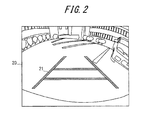
- FIG. 2 is a diagram illustrating an example of the overlay image superimposed on the captured image.
- the guide lines serving as an overlay image 21 are superimposed on a predetermined position in the captured image 20.
- the predetermined position is, for example, a position corresponding to a travelling direction of the vehicle in the captured image 20.
- the driver by seeing the overlay image 21, i.e., the guide lines, may recognize the travelling direction of the vehicle in the captured image 20.
- FIG. 3 is a diagram illustrating color of the overlay image data.
- the image processer 5 determines different colors between a first color of the overlay image data of a first frame and a second color of the overlay image data of a second frame following the first frame. For example, when frames of the captured image data input from the imaging unit 3 are assigned with an order, the image processer 5 determines a first color 3a of overlay image data 21a to be superimposed on captured image data 20a of odd frames and a second color 3b of overlay image data 21b to be superimposed on captured image data 20b of even frames.
- the colors 3a and 3b represent gradation values of a color space, such as an RGB (Red, Green, and Blue) color space, of an image displayed on the display 9.
- RGB Red, Green, and Blue
- the driver Since images corresponding to the captured image data 20a and the captured image data 20b are alternately displayed, the driver recognize images in which an afterimage of the overlay image of the odd frame and an afterimage of the overlay image of the even frame overlap with each other. At this time, therefore, the driver may recognize a neutral color (e.g., color with an intermediate value of an RGB gradation value) between the overlay image of the odd frame and the overlay image of the even frame. Accordingly, for example, when one of the colors is similar to background color of the captured image and thus hardly visible, as long as opposite color is different from the background color and easily visible, the driver may recognize the overlay image in the neutral color and, regardless of the background color, recognize an original guide line.
- a neutral color e.g., color with an intermediate value of an RGB gradation value
- the driver may recognize one of the colors that is easier for the driver to do so. Therefore, the driver may recognize an original overlay image in a difficult color by using an afterimage thereof in color which the driver has recognized.
- the colors of the overlay image data 21a and 21b may be switched by a plurality of frames. That is, the overlay image data 21 a may be superimposed on m-number of (m is an integer of 2 or higher) first frames and the overlay image data 21b maybe superimposed on the following m-number of second frames. Or, the number of first frames and the number of second frames may be different from each other.
- the driver may recognize the overlay image in the neutral color or in the color easier for the driver to recognize, and thus may recognize the original overlay image.
- the overlay image data may be superimposed on the same position in the frame. In other words, an area of the captured image to superimpose the overlay image may be minimized, thereby maximizing a visible area of the captured image.
- the colors 3a and 3b of the overlay image data 21a and 21b are determined to have a difference in at least one of the hue, the brightness, and intensity.
- the color 3a of the overlay image data 21a is a reference color
- the color 3b opposite to the reference color 3a denoted by 3b(A) in FIG. 4 may have the hue and the brightness the same as those of the reference color 3a while having the intensity different from that of the reference color 3a.
- the color 3b denoted by 3b(C) in FIG. 4 may have the hue the same as that of the reference color 3a while having the intensity and the brightness different from those of the reference color 3a.
- the color 3b may have the hue, intensity and brightness all different from those of the reference color 3a.
- the driver may recognize the neutral color between the reference color 3a and the opposite color 3b or the color easier for the driver to recognize and thus recognize the original overlay image.
- the color 3a of the overlay image data 21a and the color 3b of the overlay image data 21b are mutual complementary colors.
- the complementary colors have a relation to be located opposite to each other in a hue circle.
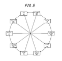
- a Munsell hue circle illustrated in FIG. 5 may be used.
- the Munsell hue circle is divided into ten sections of ten colors including five basic colors (red, yellow, green, blue, and purple) and five neutral colors therebetween (yellowish red, yellowish green, bluish green, bluish purple, and purplish red), and the ten colors are arranged into a circle being sectioned.
- This hue circle allows a selection of a combination of hues positioned opposite to each other, such as a combination of red and bluish green, a combination of yellowish red and blue, and a combination of yellow and bluish purple.
- complementary colors include ones positioned directly opposite to each other as well as ones positioned approximately opposite to each other.
- the complementary colors may be a combination of red and green or a combination of red and blue.
- other hue data may be used as a matter of course.
- the driver may recognize the color which is easier for the driver to do so and thus may recognize the original overlay image.
- FIG. 6 is a diagram illustrating a detailed configuration of the image processer 5 for conducting the image processing described above.
- the image processer 5 includes an image color determining unit 60 for determining colors of the overlay image data 21a and 21b and an image synthesizing unit 62 for superimposing the overlay image data 21a and 21b in determined colors on predetermined positions in the captured image data 20a and 20b, respectively, and outputting the resulting data to the display 9.
- the image color determination unit 60 and the image synthesizing unit 62 may be configured by using, for example, a processor for executing a processing program stored in the memory 4.
- the image color determination unit 60 reads the overlay image data 21a upon input of the captured image data 20a of the odd frame, and reads the overlay image data 21b upon input of the captured image data 20b of the even frame, from the memory 4.
- the memory 4 preliminarily stores the overlay image data 21a and 21b in different colors.
- the image synthesizing unit 62 outputs a switching signal according to the order of the frame of the captured image data to a selector 64, such that the selector 64 selects one of the overlay image data 21 a and 21b read from the memory 4 and inputs the selected one to the image synthesizing unit 62.
- the selector 64 inputs the overlay image data 21a to the image synthesizing unit 62 for the odd frame and the overlay image data 21b for the even frame.
- the image synthesizing unit 62 superimposes the overlay image data 21a and 21b on the predetermined positions in the captured image data 20a and 20b, respectively, and outputs the resulting data one after another to the display 9.
- the image color determination unit 60 determines color of the overlay image data to be superimposed based on the order of the frames of the captured image data.
- map data of color combinations may be preliminarily stored in the memory 4 for later read-out.
- the image color determination unit 60 reads overlay image data in non-specified color from the memory 4 and transmits the overlay image data together with information on determined color to the image synthesizing unit 62.
- the image synthesizing unit 62 when superimposing the overlay image data on the captured image data, sets the determined color.
- the image color determination unit 60 may determine the color of the overlay image data based on the background color around the position on which the overlay image data are superimposed in the captured image data. For example, the image color determination unit 60 acquires color of pixels around the position on which the overlay image data are superimposed in the captured image data. Then, the image color determination unit 60 reads color corresponding to the background color from, for example, the map data of a combination of the background color and the color of the overlay image data and determines the color of the overlay image data. Such map data are preliminarily stored in the memory 4.
- a complementary color of the background color and a reference color of the overlay image data corresponding thereto are associated with each other and, further, the reference color and an opposite color having difference therefrom in at least one of the hue, the brightness, and the intensity are associated with each other.
- FIG. 7 is a flowchart illustrating an operation procedure of the image processer 5 according to the present embodiment.
- the procedure illustrated in FIG. 7 is executed, for example, every time the captured image data of one frame are input.
- the image color determination unit 60 determines whether the frame is the odd frame or the even frame (S704). For the odd frame, the image color determination unit 60 reads the overlay image data 21a in the color 3a of the odd frame from the memory 4 (S706). Or, the image color determination unit 60 may set the color 3a of the odd frame to the image synthesizing unit 62. Then, the image synthesizing unit 62 combines the captured image data 20a of the odd frame and the overlay image data 21a in the color 3a and outputs thus synthesized data (S708).
- the image color determination unit 60 reads the overlay image data 21b in the color 3b of the even frame from the memory 4 (S710). Then, the image synthesizing unit 62 combines the captured image data 20b of the even frame and the overlay image data 21b in the color 3b and outputs thus synthesized data (S712).
- the image color determination unit 60 determines colors of the overlay image data 21a and 21b based on the background color of the captured image data may be inserted.
- the image color determination unit 60 instead of reading the overlay image data from the memory 4, sets the determined color for the odd frame or the even frame to the image synthesizing unit 62.
- the overlay image that is easily visible regardless of the background color and the driver's color vision may be superimposed on the captured image.
- the image color determining unit 60 includes a plurality of combinations of the overlay image data 21a and 21b that may be selected by the driver.
- the combinations are preliminarily stored in the memory 4.
- the driver may select, based on driver's taste or color vision, a color combination that is more easily visible to the driver.
- the overlay image that is more easily visible to the driver may be superimposed on the captured image.
- FIG. 8 is a flowchart illustrating a color selection procedure.
- the procedure in FIG. 8 is executed when, for example, the driver inputs an instruction of color settings by using the input device 7.
- the image color determination unit 60 controls the display 9 to display the combination read from the memory 4 (S80).
- FIG. 9 is a diagram illustrating exemplary color combinations to be selected.
- Each pattern number includes the reference color (for example, color of the odd frame) and the opposite color (color of the even frame) paired with the reference color.
- a signal corresponding to the selection is input to the image color determination unit 60 (S82).
- the image color determination unit 60 determines the selected color combination as the colors of the overlay image data 21a and 21b (S84).
- the driver may select, based on the driver's taste or color vision, the color combination that is more easily visible to the driver.
- the overlay image that is more easily visible to the driver may be superimposed on the captured image.
- the overlay image that is easily visible regardless of the background color and the driver's color vision may to be superimposed on the captured image.
Landscapes
- Engineering & Computer Science (AREA)
- General Physics & Mathematics (AREA)
- Physics & Mathematics (AREA)
- Theoretical Computer Science (AREA)
- Mechanical Engineering (AREA)
- Computer Hardware Design (AREA)
- Transportation (AREA)
- Combustion & Propulsion (AREA)
- Chemical & Material Sciences (AREA)
- Closed-Circuit Television Systems (AREA)
- Image Processing (AREA)
- Multimedia (AREA)
- Control Of Indicators Other Than Cathode Ray Tubes (AREA)
- Controls And Circuits For Display Device (AREA)
- Traffic Control Systems (AREA)
- Studio Devices (AREA)
Abstract
Description
- This application claims priority to and the benefit of Japanese Patent Application No.
2012-075043 (filed on March 28, 2012 - The present invention relates to an image processing apparatus for superimposing overlay image data on captured image data of successive frames generated by capturing surroundings of a vehicle, and also to an imaging apparatus, a vehicle drive assisting apparatus, and an image processing method.
- There is known a vehicle drive assisting apparatus that, during running of a vehicle, displays an image of surroundings of the vehicle captured by an imaging apparatus mounted on the vehicle on a display installed in the vehicle. A driver, by checking a captured image displayed on the display, may recognize obstacles around the vehicle while driving the vehicle and also, in parking, easily and accurately park the vehicle in a parking space. Further, some examples of the vehicle drive assisting apparatus display the captured image of the surroundings of the vehicle including an image serving as a drive assisting guide superimposed thereon (for example,
Patent Documents 1, 2). The image superimposed on the captured image (hereinafter, referred to as an overlay image) is, for example, a predicted path guide line of the vehicle. The captured image having the overlay image superimposed thereon allows the driver to more accurately and easily recognize a distance between the vehicle and an object as well as a width of the vehicle. -
- Patent Document 1: Japanese Patent Application Laid-Open Publication No.
2005-073203 - Patent Document 2: Japanese Patent Application Laid-Open Publication No.
2008-193521 - The overlay image, for its purpose, preferably stands out as much as possible against the captured image displayed as a background. As such, the overlay image is generally in color such as, for example, yellow and red for easy recognition to the driver. However, when the background having the overlay image superimposed thereon are in color similar to that of the overlay image, there is a risk that the overlay image becomes less visible. In particular, people with color blindness may have further difficulty in recognizing the overlay image in colors which they have difficulty in recognizing.
- Therefore, the present invention in consideration of the above problem is to provide an image processing apparatus for superimposing, on the captured image, the overlay image that is easily visible regardless of the background color and a driver's color vision, and also to provide an imaging apparatus, a drive assisting apparatus, and an image processing method.
- In order to solve the above problem, an image processing apparatus according to one embodiment of the present invention includes: an image color determination unit configured to determine color of overlay image data to be superimposed on captured image data of successive frames generated by capturing surroundings of a vehicle such that a first color of overlay image data of a first frame differs from a second color of the overlay image data of a second frame following the first frame; and an image synthesizing unit configured to superimpose the overlay image data in the first color and the overlay image data in the second color respectively on predetermined positions in the captured image data of the first frame and the second frame, and output images corresponding to the captured image data of the successive frames one after another to a display.
- The first color and second colors are determined to have a difference in at least one of hue, brightness, and intensity.
- According to another preferred embodiment, the first and second colors are determined to be complementary to each other.
- According to yet another preferred embodiment, the image color determination unit includes a plurality of selectable combinations of the first and second colors.
- According to another embodiment of the present invention, an imaging apparatus includes the image processing apparatus described above and an imaging unit for capturing surroundings of a vehicle and generating captured image data to be input to the image processing apparatus.
- According to yet another embodiment of the present invention, a vehicle drive assisting apparatus includes the imaging apparatus described above and a display installed in a vehicle together with the imaging apparatus for displaying images corresponding to captured image data of successive frames output from the imaging apparatus.
- Note that a method, a program, and a storage medium storing the program that are substantially corresponding to the above apparatus may also implement the present invention and thus included in the scope of the present invention. For data processing, each step of the method or the program, as necessary, uses a processer such as CPU (Central Processing Unit) and DSP (Digital Signal Processor) and stores input data, processed data, generated data and the like in a storage device such as HDD (Hard Disk Drive) and a memory.
- For example, an image processing method for implementing the present invention as a method includes steps of: determining color of overlay image data to be superimposed on captured image data of successive frames generated by capturing surroundings of a vehicle such that a first color of overlay image data of a first frame differs from a second color of the overlay image data of a second frame following the first frame; superimposing the overlay image data in the first color and the overlay image data in the second color respectively on predetermined positions in the captured image data of the first frame and the second frame; and outputting images corresponding to the captured image data of the successive frames one after another to a display.
- According to the present invention, an overlay image that is easily visible regardless of a background color and a driver's color vision may be superimposed on a captured image.
-
-
FIG. 1 is a diagram illustrating a configuration of a vehicle drive assisting apparatus of the present embodiment; -
FIG. 2 is a diagram illustrating an example of an overlay image superimposed on a captured image; -
FIG. 3 is a diagram illustrating color of overlay image data; -
FIG. 4 is a diagram illustrating color of the overlay image data; -
FIG. 5 is a diagram illustrating a Munsell hue circle; -
FIG. 6 is a diagram illustrating a detailed configuration of an image processer; -
FIG. 7 is a flowchart illustrating an operation procedure of the image processer ; -
FIG. 8 is a flowchart illustrating a color selection procedure; and -
FIG. 9 is a diagram illustrating exemplary color combinations of the overlay image data to be selected. - Hereinafter, a preferred embodiment of the present invention will be described in detail by way of example with reference to the accompanying drawings.
-
FIG. 1 is a diagram illustrating a configuration of a vehicle drive assisting apparatus of the present embodiment. Adrive assisting apparatus 1 installed in a vehicle includes animaging apparatus 10 for capturing surroundings of the vehicle and adisplay 9 for displaying a captured image. Thedrive assisting apparatus 1 may further include an input device 7 for receiving an input operation from a driver. Theimaging apparatus 10 includes an imagingoptical system 2, animaging unit 3, a memory (storage) 4, animage processer 5, and a controller 6. Theimaging apparatus 10 is mounted, for example, on a rear portion of the vehicle and captures an image of surroundings behind the vehicle. - The imaging
optical system 2 is an optical member for allowing light (i.e., an optical image of the surroundings of the vehicle) to enter theimaging unit 3. For example, the imagingoptical system 2 includes one or more lenses. Also, the imagingoptical system 2 may include, in addition to the lens(es), other optical members such as a filter and the like arranged in such a manner that optical axes thereof coincide with one another. - The
imaging unit 3 is mounted on the vehicle and captures an image of the surroundings of the vehicle through the imagingoptical system 2 and includes, for example, CCD (Charge Coupled Device) image sensor or CMOS (Complementary Metal Oxide Semiconductor) image sensor that include image pickup elements arranged in a two-dimensional manner for converting an optical image taken by the imagingoptical system 2 into an electrical signal. For example, theimaging unit 3 successively images at intervals of several tens of milliseconds and outputs a pixel signal corresponding to two-dimensional pixels in each of the imaging operation. Here, one imaging captures an image of one frame. Then, by the successive imaging operation, moving images composed of the captured images of successive frames are captured. Between theimaging unit 3 and theimage processer 5, an A/D converter (not shown) for converting an analog output of theimaging unit 3 into a digital signal is provided. Captured image data converted into the digital signal constitute a pixel data group of each frame. Thus, the captured image data of the successive frames are input to theimage processer 5. - The
image processer 5 corresponds to an "image processing device" for overlapping overlay image data on the captured image data and outputting the resulting data to thedisplay 9. Theimage processer 5 is constituted by using, for example, MPU (Micro Processor Unit) or LSI (Large Scale Integration). - The
memory 4 stores the overlay image data to be superimposed on the captured image data. The overlay image data are, for example, image data corresponding to a vehicle predicted path guide line. Here, the guide line is displayed overlapping the captured image in order to assist drive of the vehicle and includes, for example, a guide line indicating a vehicle predicted path trajectory, a guide line indicating a distance from the vehicle, and a guide line indicating a width of the vehicle. The guide lines may be either a straight line or a curved line. Also, a plurality of patterns of the guide line may be preliminarily stored in thememory 4 and changed based on a behavior of the vehicle such as a steering angle of the vehicle, a rotation speed difference between a left wheel and a right wheel, and a velocity of the vehicle. - The controller 6 obtains a command signal from the input device 7 and a sensor signal from various sensors mounted on the vehicle and accordingly outputs a control signal for controlling operations of the
imaging unit 3 and theimage processer 5. The command signal from the input device 7 is, for example, a command to display a guide line image or a signal for setting color of the guide line image (i.e., an overlay image). The controller 6 is constituted by using, for example, the MPU (Micro Processor Unit) or the LSI (Large Scale Integration). - The input device 7 is installed in the vicinity of a driver's seat and, by receiving various input operations from the driver, generates command signals corresponding to the input operations. The input device 7 is constituted by using, for example, a keyboard or a touch panel. The command signal from the input device 7 is transmitted to the controller 6 via a
line 8. Theline 8 may be an in-vehicle network such as CAN (Controller Area Network) or a dedicated line. - The
display 9 is installed in the vicinity of the driver's seat and displays the captured image to the driver. Thedisplay 9 includes, for example, a liquid crystal display and a drive circuit thereof and displays the captured image corresponding to the captured image data in which the overlay image data output by theimage processer 5 is superimposed. Thedisplay 9 displays moving images by continuously displaying the captured image data of the successive frames. -
FIG. 2 is a diagram illustrating an example of the overlay image superimposed on the captured image. In this example, on a capturedimage 20 of the surroundings behind thevehicle 20, the guide lines serving as anoverlay image 21 are superimposed. Theoverlay image 21 is superimposed on a predetermined position in the capturedimage 20. The predetermined position is, for example, a position corresponding to a travelling direction of the vehicle in the capturedimage 20. The driver, by seeing theoverlay image 21, i.e., the guide lines, may recognize the travelling direction of the vehicle in the capturedimage 20. -
FIG. 3 is a diagram illustrating color of the overlay image data. According to the present embodiment, theimage processer 5 determines different colors between a first color of the overlay image data of a first frame and a second color of the overlay image data of a second frame following the first frame. For example, when frames of the captured image data input from theimaging unit 3 are assigned with an order, theimage processer 5 determines afirst color 3a ofoverlay image data 21a to be superimposed on capturedimage data 20a of odd frames and asecond color 3b ofoverlay image data 21b to be superimposed on capturedimage data 20b of even frames. For example, thecolors display 9. Here, a difference between thecolor 3a and thecolor 3b corresponds to a difference in a hatching pattern. - Since images corresponding to the captured
image data 20a and the capturedimage data 20b are alternately displayed, the driver recognize images in which an afterimage of the overlay image of the odd frame and an afterimage of the overlay image of the even frame overlap with each other. At this time, therefore, the driver may recognize a neutral color (e.g., color with an intermediate value of an RGB gradation value) between the overlay image of the odd frame and the overlay image of the even frame. Accordingly, for example, when one of the colors is similar to background color of the captured image and thus hardly visible, as long as opposite color is different from the background color and easily visible, the driver may recognize the overlay image in the neutral color and, regardless of the background color, recognize an original guide line. - Further, when the driver has color blindness and distinguishes a difference in hue as a difference in brightness, the driver may recognize one of the colors that is easier for the driver to do so. Therefore, the driver may recognize an original overlay image in a difficult color by using an afterimage thereof in color which the driver has recognized.
- Although in the above description the colors of the
overlay image data overlay image data overlay image data 21 a may be superimposed on m-number of (m is an integer of 2 or higher) first frames and theoverlay image data 21b maybe superimposed on the following m-number of second frames. Or, the number of first frames and the number of second frames may be different from each other. When thecolor 3a of theoverlay image data 21a and thecolor 3b of theoverlay image data 21b are alternately switched, the driver may recognize the overlay image in the neutral color or in the color easier for the driver to recognize, and thus may recognize the original overlay image. - Further, since the driver may recognize the color from the afterimage, the overlay image data may be superimposed on the same position in the frame. In other words, an area of the captured image to superimpose the overlay image may be minimized, thereby maximizing a visible area of the captured image.
- According to a preferred mode of the present embodiment, the
colors overlay image data color 3a of theoverlay image data 21a is a reference color, when the background color of the captured image is gray and thereference color 3a is red and, the brightness of the background color and that of thereference color 3a coincide with each other, thecolor 3b opposite to thereference color 3a denoted by 3b(A) inFIG. 4 may have the hue and the brightness the same as those of thereference color 3a while having the intensity different from that of thereference color 3a. Or, thecolor 3b denoted by 3b(B) inFIG. 4 may have the hue and the intensity the same as those of thereference color 3a while having the brightness different from that of thereference color 3a. Or, thecolor 3b denoted by 3b(C) inFIG. 4 may have the hue the same as that of thereference color 3a while having the intensity and the brightness different from those of thereference color 3a. Or, thecolor 3b may have the hue, intensity and brightness all different from those of thereference color 3a. - Thereby, the driver may recognize the neutral color between the
reference color 3a and theopposite color 3b or the color easier for the driver to recognize and thus recognize the original overlay image. - According to a more preferred mode of the present embodiment, the
color 3a of theoverlay image data 21a and thecolor 3b of theoverlay image data 21b are mutual complementary colors. The complementary colors have a relation to be located opposite to each other in a hue circle. For selection of the hue of the complementary colors, a Munsell hue circle illustrated inFIG. 5 , for example, may be used. The Munsell hue circle is divided into ten sections of ten colors including five basic colors (red, yellow, green, blue, and purple) and five neutral colors therebetween (yellowish red, yellowish green, bluish green, bluish purple, and purplish red), and the ten colors are arranged into a circle being sectioned. This hue circle allows a selection of a combination of hues positioned opposite to each other, such as a combination of red and bluish green, a combination of yellowish red and blue, and a combination of yellow and bluish purple. Note that, according to the present embodiment, complementary colors include ones positioned directly opposite to each other as well as ones positioned approximately opposite to each other. For example, the complementary colors may be a combination of red and green or a combination of red and blue. Further, in selection of the complementary colors, other hue data may be used as a matter of course. - Since the
color 3a of theoverlay image data 21a and thecolor 3b of theoverlay image data 21b are complementary color to each other, when, for example, the driver has the color blindness such as color weakness and distinguishes between the complementally colors by their brightness, the driver may recognize the color which is easier for the driver to do so and thus may recognize the original overlay image. -
FIG. 6 is a diagram illustrating a detailed configuration of theimage processer 5 for conducting the image processing described above. Theimage processer 5 includes an imagecolor determining unit 60 for determining colors of theoverlay image data image synthesizing unit 62 for superimposing theoverlay image data image data display 9. The imagecolor determination unit 60 and theimage synthesizing unit 62 may be configured by using, for example, a processor for executing a processing program stored in thememory 4. - For example, the image
color determination unit 60 reads theoverlay image data 21a upon input of the capturedimage data 20a of the odd frame, and reads theoverlay image data 21b upon input of the capturedimage data 20b of the even frame, from thememory 4. Here, thememory 4 preliminarily stores theoverlay image data - The
image synthesizing unit 62 outputs a switching signal according to the order of the frame of the captured image data to aselector 64, such that theselector 64 selects one of theoverlay image data memory 4 and inputs the selected one to theimage synthesizing unit 62. For example, theselector 64 inputs theoverlay image data 21a to theimage synthesizing unit 62 for the odd frame and theoverlay image data 21b for the even frame. Then, theimage synthesizing unit 62 superimposes theoverlay image data image data display 9. - Alternatively, the following configuration is also possible. That is, for example, the image
color determination unit 60 determines color of the overlay image data to be superimposed based on the order of the frames of the captured image data. In this case, for example, map data of color combinations may be preliminarily stored in thememory 4 for later read-out. Then, the imagecolor determination unit 60 reads overlay image data in non-specified color from thememory 4 and transmits the overlay image data together with information on determined color to theimage synthesizing unit 62. Theimage synthesizing unit 62, when superimposing the overlay image data on the captured image data, sets the determined color. - Further, the image
color determination unit 60 may determine the color of the overlay image data based on the background color around the position on which the overlay image data are superimposed in the captured image data. For example, the imagecolor determination unit 60 acquires color of pixels around the position on which the overlay image data are superimposed in the captured image data. Then, the imagecolor determination unit 60 reads color corresponding to the background color from, for example, the map data of a combination of the background color and the color of the overlay image data and determines the color of the overlay image data. Such map data are preliminarily stored in thememory 4. In the map data, for example, a complementary color of the background color and a reference color of the overlay image data corresponding thereto are associated with each other and, further, the reference color and an opposite color having difference therefrom in at least one of the hue, the brightness, and the intensity are associated with each other. -
FIG. 7 is a flowchart illustrating an operation procedure of theimage processer 5 according to the present embodiment. The procedure illustrated inFIG. 7 is executed, for example, every time the captured image data of one frame are input. - The image
color determination unit 60, in response to the captured image data input thereto (S702), determines whether the frame is the odd frame or the even frame (S704). For the odd frame, the imagecolor determination unit 60 reads theoverlay image data 21a in thecolor 3a of the odd frame from the memory 4 (S706). Or, the imagecolor determination unit 60 may set thecolor 3a of the odd frame to theimage synthesizing unit 62. Then, theimage synthesizing unit 62 combines the capturedimage data 20a of the odd frame and theoverlay image data 21a in thecolor 3a and outputs thus synthesized data (S708). For the even frame, on the other hand, the imagecolor determination unit 60 reads theoverlay image data 21b in thecolor 3b of the even frame from the memory 4 (S710). Then, theimage synthesizing unit 62 combines the capturedimage data 20b of the even frame and theoverlay image data 21b in thecolor 3b and outputs thus synthesized data (S712). - Note that in the procedure described above, between S702 and S704, a step that the image
color determination unit 60 determines colors of theoverlay image data color determination unit 60, instead of reading the overlay image data from thememory 4, sets the determined color for the odd frame or the even frame to theimage synthesizing unit 62. - According to the present embodiment, as described above, the overlay image that is easily visible regardless of the background color and the driver's color vision may be superimposed on the captured image.
- According to a variation example of the present embodiment, the image
color determining unit 60 includes a plurality of combinations of theoverlay image data memory 4. According to this variation example, the driver may select, based on driver's taste or color vision, a color combination that is more easily visible to the driver. Thus, the overlay image that is more easily visible to the driver may be superimposed on the captured image. -
FIG. 8 is a flowchart illustrating a color selection procedure. The procedure inFIG. 8 is executed when, for example, the driver inputs an instruction of color settings by using the input device 7. The imagecolor determination unit 60 controls thedisplay 9 to display the combination read from the memory 4 (S80). -
FIG. 9 is a diagram illustrating exemplary color combinations to be selected. Each pattern number includes the reference color (for example, color of the odd frame) and the opposite color (color of the even frame) paired with the reference color. - Referring back to
FIG. 8 , when the driver selects a color combination by using the input device 7 (for example, selects a pattern number inFIG. 9 ), a signal corresponding to the selection is input to the image color determination unit 60 (S82). In response thereto, the imagecolor determination unit 60 determines the selected color combination as the colors of theoverlay image data - According to this variation example, the driver may select, based on the driver's taste or color vision, the color combination that is more easily visible to the driver. Thus, the overlay image that is more easily visible to the driver may be superimposed on the captured image.
- Although the present invention has been described based on the figures and the embodiments, it is to be understood that various modifications and changes may be implemented based on the present disclosure by those who are ordinarily skilled in the art. Accordingly, such modifications and changes are included in a scope of the present invention. For example, functions and the like included in each means and each step may be rearranged without logical inconsistency, so as to combine a plurality of means or steps together or to divide them.
- According to the present embodiments, as described above, the overlay image that is easily visible regardless of the background color and the driver's color vision may to be superimposed on the captured image.
-
- 1:
- drive assisting apparatus
- 10:
- imaging apparatus
- 5:
- image processer
- 60:
- image color determination unit
- 62:
- image synthesizing unit
- 20a, 20b:
- captured image data
- 21a, 21b:
- overlay image data
Claims (8)
- An image processing apparatus comprising:an image color determination unit configured to determine color of overlay image data to be superimposed on captured image data of successive frames generated by capturing surroundings of a vehicle such that a first color of overlay image data of a first frame differs from a second color of the overlay image data of a second frame following the first frame; andan image synthesizing unit configured to superimpose the overlay image data in the first color and the overlay image data in the second color respectively on predetermined positions in the captured image data of the first frame and the second frame, and output images corresponding to the captured image data of the successive frames one after another to a display.
- The image processing apparatus according to claim 1, wherein the first and second colors are determined to have a difference in at least one of hue, brightness, and intensity.
- The image processing apparatus according to claim 2, wherein the first and second colors are determined to be complementary to each other.
- The image processing apparatus according to any one of claims 1 to 3, wherein the image color determination unit includes a plurality of selectable combinations of the first and second colors.
- The image processing apparatus according to any one of claims 1 to 3, wherein the image color determination unit determines the first color based on color of a captured image.
- An imaging apparatus comprising:the image processing apparatus according to any one of claims 1 to 5; andan imaging unit configured to capture surroundings of a vehicle and generating captured image data to be input to the image processing apparatus.
- A vehicle drive assisting apparatus comprising:the imaging apparatus according to claim 6; anda display installed in a vehicle together with the imaging apparatus configured to display images corresponding to captured image data of successive frames output from the imaging apparatus.
- An image processing method including steps of:determining color of overlay image data to be superimposed on captured image data of successive frames generated by capturing surroundings of a vehicle such that a first color of overlay image data of a first frame differs from a second color of the overlay image data of a second frame following the first frame;superimposing the overlay image data in the first color and the overlay image data in the second color respectively on predetermined positions in the captured image data of the first frame and the second frame; andoutputting images corresponding to the captured image data of the successive frames one after another to a display.
Applications Claiming Priority (2)
| Application Number | Priority Date | Filing Date | Title |
|---|---|---|---|
| JP2012075043A JP5960466B2 (en) | 2012-03-28 | 2012-03-28 | Image processing apparatus, imaging apparatus, vehicle driving support apparatus, and image processing method |
| PCT/JP2013/002036 WO2013145710A1 (en) | 2012-03-28 | 2013-03-26 | Image processing apparatus, image capturing apparatus, vehicle drive assisting apparatus, and image processing method |
Publications (3)
| Publication Number | Publication Date |
|---|---|
| EP2833629A1 true EP2833629A1 (en) | 2015-02-04 |
| EP2833629A4 EP2833629A4 (en) | 2015-12-09 |
| EP2833629B1 EP2833629B1 (en) | 2019-09-04 |
Family
ID=49259009
Family Applications (1)
| Application Number | Title | Priority Date | Filing Date |
|---|---|---|---|
| EP13769235.6A Active EP2833629B1 (en) | 2012-03-28 | 2013-03-26 | Image processing apparatus, image capturing apparatus, vehicle drive assisting apparatus, and image processing method |
Country Status (4)
| Country | Link |
|---|---|
| US (1) | US9663035B2 (en) |
| EP (1) | EP2833629B1 (en) |
| JP (1) | JP5960466B2 (en) |
| WO (1) | WO2013145710A1 (en) |
Cited By (2)
| Publication number | Priority date | Publication date | Assignee | Title |
|---|---|---|---|---|
| WO2016131104A1 (en) * | 2015-02-18 | 2016-08-25 | Federation Enterprises (Wa) Pty Ltd | Bicycle camera and bicycle camera system |
| GB2608362A (en) * | 2021-06-24 | 2023-01-04 | Continental Automotive Gmbh | A method for adapting color of an overlay displayed in a display unit of a vehicle and a system thereof |
Families Citing this family (13)
| Publication number | Priority date | Publication date | Assignee | Title |
|---|---|---|---|---|
| JP2013224081A (en) * | 2012-04-20 | 2013-10-31 | Kyocera Corp | Image processing device and driving assisting method |
| JP6318470B2 (en) * | 2013-05-15 | 2018-05-09 | ソニー株式会社 | Display control device, display control method, and recording medium |
| US10515367B2 (en) * | 2014-03-31 | 2019-12-24 | Ncr Corporation | Fraud detection in self-service terminal |
| JP6958117B2 (en) * | 2017-08-29 | 2021-11-02 | 株式会社アイシン | Parking support device |
| JP7016146B2 (en) * | 2017-11-22 | 2022-02-04 | 小橋工業株式会社 | Agricultural work machine |
| US10657677B2 (en) | 2017-12-04 | 2020-05-19 | International Business Machines Corporation | Cognitive situation-aware vision deficiency remediation |
| US10377304B2 (en) | 2017-12-04 | 2019-08-13 | International Business Machines Corporation | Cognitive situation-aware vision deficiency remediation |
| US10565872B2 (en) | 2017-12-04 | 2020-02-18 | International Business Machines Corporation | Cognitive situation-aware vision deficiency remediation |
| US10740938B2 (en) | 2017-12-04 | 2020-08-11 | International Business Machines Corporation | Cognitive situation-aware vision deficiency remediation |
| CN111942288B (en) * | 2019-05-14 | 2022-01-28 | 欧特明电子股份有限公司 | Vehicle image system and vehicle positioning method using vehicle image |
| JP7619221B2 (en) * | 2021-09-16 | 2025-01-22 | トヨタ自動車株式会社 | Vehicle display device, vehicle display system, vehicle display method and program |
| CN116320729A (en) * | 2023-03-27 | 2023-06-23 | 维沃移动通信有限公司 | Image processing method, device, electronic device and readable storage medium |
| CN121219768A (en) * | 2023-06-01 | 2025-12-26 | 交互数字Ce专利控股有限公司 | Quality constraint method and apparatus for energy reduction control of visual content using alternating complementary colors |
Family Cites Families (15)
| Publication number | Priority date | Publication date | Assignee | Title |
|---|---|---|---|---|
| US6822563B2 (en) * | 1997-09-22 | 2004-11-23 | Donnelly Corporation | Vehicle imaging system with accessory control |
| US6396397B1 (en) * | 1993-02-26 | 2002-05-28 | Donnelly Corporation | Vehicle imaging system with stereo imaging |
| JP3485165B2 (en) | 1999-03-30 | 2004-01-13 | 矢崎総業株式会社 | Back monitor device for vehicles |
| US6411867B1 (en) | 1999-10-27 | 2002-06-25 | Fujitsu Ten Limited | Vehicle driving support system, and steering angle detection device |
| JP2001331168A (en) * | 2000-05-24 | 2001-11-30 | Matsushita Electric Ind Co Ltd | Image display device |
| JP2002010163A (en) * | 2000-06-22 | 2002-01-11 | Mitsubishi Electric Corp | OSD circuit |
| US6674878B2 (en) * | 2001-06-07 | 2004-01-06 | Facet Technology Corp. | System for automated determination of retroreflectivity of road signs and other reflective objects |
| JP2005073203A (en) | 2003-08-28 | 2005-03-17 | Nissan Motor Co Ltd | Vehicle display device |
| US7356408B2 (en) * | 2003-10-17 | 2008-04-08 | Fuji Jukogyo Kabushiki Kaisha | Information display apparatus and information display method |
| JP2008193521A (en) | 2007-02-06 | 2008-08-21 | Toyota Motor Corp | Object display device |
| JP5380941B2 (en) * | 2007-10-01 | 2014-01-08 | 日産自動車株式会社 | Parking support apparatus and method |
| EP2285109B1 (en) * | 2008-05-29 | 2018-11-28 | Fujitsu Limited | Vehicle image processor, and vehicle image processing system |
| JP5178361B2 (en) * | 2008-07-09 | 2013-04-10 | 本田技研工業株式会社 | Driving assistance device |
| JP5118605B2 (en) * | 2008-10-30 | 2013-01-16 | クラリオン株式会社 | Vehicle periphery image display system |
| US9126525B2 (en) * | 2009-02-27 | 2015-09-08 | Magna Electronics Inc. | Alert system for vehicle |
-
2012
- 2012-03-28 JP JP2012075043A patent/JP5960466B2/en not_active Expired - Fee Related
-
2013
- 2013-03-26 US US14/388,511 patent/US9663035B2/en not_active Expired - Fee Related
- 2013-03-26 WO PCT/JP2013/002036 patent/WO2013145710A1/en not_active Ceased
- 2013-03-26 EP EP13769235.6A patent/EP2833629B1/en active Active
Cited By (2)
| Publication number | Priority date | Publication date | Assignee | Title |
|---|---|---|---|---|
| WO2016131104A1 (en) * | 2015-02-18 | 2016-08-25 | Federation Enterprises (Wa) Pty Ltd | Bicycle camera and bicycle camera system |
| GB2608362A (en) * | 2021-06-24 | 2023-01-04 | Continental Automotive Gmbh | A method for adapting color of an overlay displayed in a display unit of a vehicle and a system thereof |
Also Published As
| Publication number | Publication date |
|---|---|
| JP5960466B2 (en) | 2016-08-02 |
| JP2013207597A (en) | 2013-10-07 |
| EP2833629A4 (en) | 2015-12-09 |
| US9663035B2 (en) | 2017-05-30 |
| EP2833629B1 (en) | 2019-09-04 |
| WO2013145710A1 (en) | 2013-10-03 |
| US20150062341A1 (en) | 2015-03-05 |
Similar Documents
| Publication | Publication Date | Title |
|---|---|---|
| EP2833629B1 (en) | Image processing apparatus, image capturing apparatus, vehicle drive assisting apparatus, and image processing method | |
| US9832426B2 (en) | Around view monitor system and monitoring method | |
| EP2410740B1 (en) | Surrounding-area monitoring device for vehicles and surrounding-area image display method for vehicles | |
| US20120169875A1 (en) | Rearward view assistance apparatus | |
| JP5643344B2 (en) | Vehicle travel support device | |
| JP2012148710A (en) | Image display apparatus | |
| JP2012121527A (en) | Image display device | |
| WO2019026747A1 (en) | Augmented real image display device for vehicle | |
| JP4801654B2 (en) | Composite image generator | |
| EP2784572A1 (en) | Head-up display device and display method of head-up display device | |
| JP5067136B2 (en) | Vehicle periphery image processing apparatus and vehicle periphery state presentation method | |
| JP5187574B2 (en) | Vehicle display device | |
| JP6297630B2 (en) | Image processing apparatus, imaging apparatus, vehicle driving support apparatus, and image processing method | |
| JP2012166689A (en) | Driving assistance apparatus | |
| CN106067942A (en) | Image processing apparatus, image processing method and mobile unit | |
| CN113498518B (en) | Image processing device | |
| KR20130029962A (en) | Image display device for vehicle and method for displaying rapid change of image inputted from camera for vehicle | |
| KR102125738B1 (en) | A parking assisting system | |
| JP2018085008A (en) | Image processing apparatus and image processing method of image processing apparatus | |
| JP4846627B2 (en) | Display control device | |
| JP2007081932A (en) | Vehicle periphery visual recognition device | |
| JP2008301238A (en) | Monitoring area setting apparatus and monitoring area setting method for video monitoring system | |
| JP2007314023A (en) | Driving support system | |
| JP5089875B2 (en) | Image information superimposing method and image information display device | |
| JP2008103825A (en) | Display control device |
Legal Events
| Date | Code | Title | Description |
|---|---|---|---|
| PUAI | Public reference made under article 153(3) epc to a published international application that has entered the european phase |
Free format text: ORIGINAL CODE: 0009012 |
|
| 17P | Request for examination filed |
Effective date: 20140926 |
|
| AK | Designated contracting states |
Kind code of ref document: A1 Designated state(s): AL AT BE BG CH CY CZ DE DK EE ES FI FR GB GR HR HU IE IS IT LI LT LU LV MC MK MT NL NO PL PT RO RS SE SI SK SM TR |
|
| AX | Request for extension of the european patent |
Extension state: BA ME |
|
| DAX | Request for extension of the european patent (deleted) | ||
| RIC1 | Information provided on ipc code assigned before grant |
Ipc: G09G 5/02 20060101ALI20150714BHEP Ipc: B60R 1/00 20060101ALI20150714BHEP Ipc: G09G 5/377 20060101ALI20150714BHEP Ipc: G09G 5/00 20060101ALI20150714BHEP Ipc: H04N 7/18 20060101AFI20150714BHEP Ipc: B60R 21/00 20060101ALI20150714BHEP Ipc: G08G 1/16 20060101ALI20150714BHEP |
|
| RA4 | Supplementary search report drawn up and despatched (corrected) |
Effective date: 20151106 |
|
| RIC1 | Information provided on ipc code assigned before grant |
Ipc: B60R 21/00 20060101ALI20151102BHEP Ipc: G09G 5/00 20060101ALI20151102BHEP Ipc: G09G 5/02 20060101ALI20151102BHEP Ipc: H04N 7/18 20060101AFI20151102BHEP Ipc: B60R 1/00 20060101ALI20151102BHEP Ipc: G09G 5/377 20060101ALI20151102BHEP Ipc: G08G 1/16 20060101ALI20151102BHEP |
|
| 17Q | First examination report despatched |
Effective date: 20161005 |
|
| STAA | Information on the status of an ep patent application or granted ep patent |
Free format text: STATUS: EXAMINATION IS IN PROGRESS |
|
| GRAP | Despatch of communication of intention to grant a patent |
Free format text: ORIGINAL CODE: EPIDOSNIGR1 |
|
| STAA | Information on the status of an ep patent application or granted ep patent |
Free format text: STATUS: GRANT OF PATENT IS INTENDED |
|
| INTG | Intention to grant announced |
Effective date: 20190102 |
|
| GRAS | Grant fee paid |
Free format text: ORIGINAL CODE: EPIDOSNIGR3 |
|
| GRAA | (expected) grant |
Free format text: ORIGINAL CODE: 0009210 |
|
| STAA | Information on the status of an ep patent application or granted ep patent |
Free format text: STATUS: THE PATENT HAS BEEN GRANTED |
|
| AK | Designated contracting states |
Kind code of ref document: B1 Designated state(s): AL AT BE BG CH CY CZ DE DK EE ES FI FR GB GR HR HU IE IS IT LI LT LU LV MC MK MT NL NO PL PT RO RS SE SI SK SM TR |
|
| REG | Reference to a national code |
Ref country code: GB Ref legal event code: FG4D |
|
| REG | Reference to a national code |
Ref country code: CH Ref legal event code: EP |
|
| REG | Reference to a national code |
Ref country code: AT Ref legal event code: REF Ref document number: 1177028 Country of ref document: AT Kind code of ref document: T Effective date: 20190915 |
|
| REG | Reference to a national code |
Ref country code: DE Ref legal event code: R096 Ref document number: 602013060063 Country of ref document: DE Ref country code: IE Ref legal event code: FG4D |
|
| REG | Reference to a national code |
Ref country code: NL Ref legal event code: MP Effective date: 20190904 |
|
| REG | Reference to a national code |
Ref country code: LT Ref legal event code: MG4D |
|
| PG25 | Lapsed in a contracting state [announced via postgrant information from national office to epo] |
Ref country code: BG Free format text: LAPSE BECAUSE OF FAILURE TO SUBMIT A TRANSLATION OF THE DESCRIPTION OR TO PAY THE FEE WITHIN THE PRESCRIBED TIME-LIMIT Effective date: 20191204 Ref country code: SE Free format text: LAPSE BECAUSE OF FAILURE TO SUBMIT A TRANSLATION OF THE DESCRIPTION OR TO PAY THE FEE WITHIN THE PRESCRIBED TIME-LIMIT Effective date: 20190904 Ref country code: NO Free format text: LAPSE BECAUSE OF FAILURE TO SUBMIT A TRANSLATION OF THE DESCRIPTION OR TO PAY THE FEE WITHIN THE PRESCRIBED TIME-LIMIT Effective date: 20191204 Ref country code: FI Free format text: LAPSE BECAUSE OF FAILURE TO SUBMIT A TRANSLATION OF THE DESCRIPTION OR TO PAY THE FEE WITHIN THE PRESCRIBED TIME-LIMIT Effective date: 20190904 Ref country code: LT Free format text: LAPSE BECAUSE OF FAILURE TO SUBMIT A TRANSLATION OF THE DESCRIPTION OR TO PAY THE FEE WITHIN THE PRESCRIBED TIME-LIMIT Effective date: 20190904 Ref country code: HR Free format text: LAPSE BECAUSE OF FAILURE TO SUBMIT A TRANSLATION OF THE DESCRIPTION OR TO PAY THE FEE WITHIN THE PRESCRIBED TIME-LIMIT Effective date: 20190904 |
|
| PG25 | Lapsed in a contracting state [announced via postgrant information from national office to epo] |
Ref country code: GR Free format text: LAPSE BECAUSE OF FAILURE TO SUBMIT A TRANSLATION OF THE DESCRIPTION OR TO PAY THE FEE WITHIN THE PRESCRIBED TIME-LIMIT Effective date: 20191205 Ref country code: LV Free format text: LAPSE BECAUSE OF FAILURE TO SUBMIT A TRANSLATION OF THE DESCRIPTION OR TO PAY THE FEE WITHIN THE PRESCRIBED TIME-LIMIT Effective date: 20190904 Ref country code: AL Free format text: LAPSE BECAUSE OF FAILURE TO SUBMIT A TRANSLATION OF THE DESCRIPTION OR TO PAY THE FEE WITHIN THE PRESCRIBED TIME-LIMIT Effective date: 20190904 Ref country code: RS Free format text: LAPSE BECAUSE OF FAILURE TO SUBMIT A TRANSLATION OF THE DESCRIPTION OR TO PAY THE FEE WITHIN THE PRESCRIBED TIME-LIMIT Effective date: 20190904 Ref country code: ES Free format text: LAPSE BECAUSE OF FAILURE TO SUBMIT A TRANSLATION OF THE DESCRIPTION OR TO PAY THE FEE WITHIN THE PRESCRIBED TIME-LIMIT Effective date: 20190904 |
|
| REG | Reference to a national code |
Ref country code: AT Ref legal event code: MK05 Ref document number: 1177028 Country of ref document: AT Kind code of ref document: T Effective date: 20190904 |
|
| PG25 | Lapsed in a contracting state [announced via postgrant information from national office to epo] |
Ref country code: PT Free format text: LAPSE BECAUSE OF FAILURE TO SUBMIT A TRANSLATION OF THE DESCRIPTION OR TO PAY THE FEE WITHIN THE PRESCRIBED TIME-LIMIT Effective date: 20200106 Ref country code: EE Free format text: LAPSE BECAUSE OF FAILURE TO SUBMIT A TRANSLATION OF THE DESCRIPTION OR TO PAY THE FEE WITHIN THE PRESCRIBED TIME-LIMIT Effective date: 20190904 Ref country code: PL Free format text: LAPSE BECAUSE OF FAILURE TO SUBMIT A TRANSLATION OF THE DESCRIPTION OR TO PAY THE FEE WITHIN THE PRESCRIBED TIME-LIMIT Effective date: 20190904 Ref country code: IT Free format text: LAPSE BECAUSE OF FAILURE TO SUBMIT A TRANSLATION OF THE DESCRIPTION OR TO PAY THE FEE WITHIN THE PRESCRIBED TIME-LIMIT Effective date: 20190904 Ref country code: NL Free format text: LAPSE BECAUSE OF FAILURE TO SUBMIT A TRANSLATION OF THE DESCRIPTION OR TO PAY THE FEE WITHIN THE PRESCRIBED TIME-LIMIT Effective date: 20190904 Ref country code: AT Free format text: LAPSE BECAUSE OF FAILURE TO SUBMIT A TRANSLATION OF THE DESCRIPTION OR TO PAY THE FEE WITHIN THE PRESCRIBED TIME-LIMIT Effective date: 20190904 Ref country code: RO Free format text: LAPSE BECAUSE OF FAILURE TO SUBMIT A TRANSLATION OF THE DESCRIPTION OR TO PAY THE FEE WITHIN THE PRESCRIBED TIME-LIMIT Effective date: 20190904 |
|
| PG25 | Lapsed in a contracting state [announced via postgrant information from national office to epo] |
Ref country code: IS Free format text: LAPSE BECAUSE OF FAILURE TO SUBMIT A TRANSLATION OF THE DESCRIPTION OR TO PAY THE FEE WITHIN THE PRESCRIBED TIME-LIMIT Effective date: 20200224 Ref country code: CZ Free format text: LAPSE BECAUSE OF FAILURE TO SUBMIT A TRANSLATION OF THE DESCRIPTION OR TO PAY THE FEE WITHIN THE PRESCRIBED TIME-LIMIT Effective date: 20190904 Ref country code: SK Free format text: LAPSE BECAUSE OF FAILURE TO SUBMIT A TRANSLATION OF THE DESCRIPTION OR TO PAY THE FEE WITHIN THE PRESCRIBED TIME-LIMIT Effective date: 20190904 Ref country code: SM Free format text: LAPSE BECAUSE OF FAILURE TO SUBMIT A TRANSLATION OF THE DESCRIPTION OR TO PAY THE FEE WITHIN THE PRESCRIBED TIME-LIMIT Effective date: 20190904 |
|
| REG | Reference to a national code |
Ref country code: DE Ref legal event code: R097 Ref document number: 602013060063 Country of ref document: DE |
|
| PLBE | No opposition filed within time limit |
Free format text: ORIGINAL CODE: 0009261 |
|
| STAA | Information on the status of an ep patent application or granted ep patent |
Free format text: STATUS: NO OPPOSITION FILED WITHIN TIME LIMIT |
|
| PG2D | Information on lapse in contracting state deleted |
Ref country code: IS |
|
| PG25 | Lapsed in a contracting state [announced via postgrant information from national office to epo] |
Ref country code: DK Free format text: LAPSE BECAUSE OF FAILURE TO SUBMIT A TRANSLATION OF THE DESCRIPTION OR TO PAY THE FEE WITHIN THE PRESCRIBED TIME-LIMIT Effective date: 20190904 Ref country code: IS Free format text: LAPSE BECAUSE OF FAILURE TO SUBMIT A TRANSLATION OF THE DESCRIPTION OR TO PAY THE FEE WITHIN THE PRESCRIBED TIME-LIMIT Effective date: 20200105 |
|
| 26N | No opposition filed |
Effective date: 20200605 |
|
| PG25 | Lapsed in a contracting state [announced via postgrant information from national office to epo] |
Ref country code: SI Free format text: LAPSE BECAUSE OF FAILURE TO SUBMIT A TRANSLATION OF THE DESCRIPTION OR TO PAY THE FEE WITHIN THE PRESCRIBED TIME-LIMIT Effective date: 20190904 |
|
| PG25 | Lapsed in a contracting state [announced via postgrant information from national office to epo] |
Ref country code: MC Free format text: LAPSE BECAUSE OF FAILURE TO SUBMIT A TRANSLATION OF THE DESCRIPTION OR TO PAY THE FEE WITHIN THE PRESCRIBED TIME-LIMIT Effective date: 20190904 |
|
| REG | Reference to a national code |
Ref country code: CH Ref legal event code: PL |
|
| REG | Reference to a national code |
Ref country code: BE Ref legal event code: MM Effective date: 20200331 |
|
| PG25 | Lapsed in a contracting state [announced via postgrant information from national office to epo] |
Ref country code: LU Free format text: LAPSE BECAUSE OF NON-PAYMENT OF DUE FEES Effective date: 20200326 |
|
| PG25 | Lapsed in a contracting state [announced via postgrant information from national office to epo] |
Ref country code: CH Free format text: LAPSE BECAUSE OF NON-PAYMENT OF DUE FEES Effective date: 20200331 Ref country code: IE Free format text: LAPSE BECAUSE OF NON-PAYMENT OF DUE FEES Effective date: 20200326 Ref country code: LI Free format text: LAPSE BECAUSE OF NON-PAYMENT OF DUE FEES Effective date: 20200331 |
|
| PG25 | Lapsed in a contracting state [announced via postgrant information from national office to epo] |
Ref country code: BE Free format text: LAPSE BECAUSE OF NON-PAYMENT OF DUE FEES Effective date: 20200331 |
|
| PG25 | Lapsed in a contracting state [announced via postgrant information from national office to epo] |
Ref country code: TR Free format text: LAPSE BECAUSE OF FAILURE TO SUBMIT A TRANSLATION OF THE DESCRIPTION OR TO PAY THE FEE WITHIN THE PRESCRIBED TIME-LIMIT Effective date: 20190904 Ref country code: MT Free format text: LAPSE BECAUSE OF FAILURE TO SUBMIT A TRANSLATION OF THE DESCRIPTION OR TO PAY THE FEE WITHIN THE PRESCRIBED TIME-LIMIT Effective date: 20190904 Ref country code: CY Free format text: LAPSE BECAUSE OF FAILURE TO SUBMIT A TRANSLATION OF THE DESCRIPTION OR TO PAY THE FEE WITHIN THE PRESCRIBED TIME-LIMIT Effective date: 20190904 |
|
| PG25 | Lapsed in a contracting state [announced via postgrant information from national office to epo] |
Ref country code: MK Free format text: LAPSE BECAUSE OF FAILURE TO SUBMIT A TRANSLATION OF THE DESCRIPTION OR TO PAY THE FEE WITHIN THE PRESCRIBED TIME-LIMIT Effective date: 20190904 |
|
| P01 | Opt-out of the competence of the unified patent court (upc) registered |
Effective date: 20230508 |
|
| PGFP | Annual fee paid to national office [announced via postgrant information from national office to epo] |
Ref country code: DE Payment date: 20250128 Year of fee payment: 13 |
|
| PGFP | Annual fee paid to national office [announced via postgrant information from national office to epo] |
Ref country code: FR Payment date: 20250210 Year of fee payment: 13 |
|
| PGFP | Annual fee paid to national office [announced via postgrant information from national office to epo] |
Ref country code: GB Payment date: 20250130 Year of fee payment: 13 |