EP2833554B1 - Kodierer und Dekodierer - Google Patents
Kodierer und Dekodierer Download PDFInfo
- Publication number
- EP2833554B1 EP2833554B1 EP13306105.1A EP13306105A EP2833554B1 EP 2833554 B1 EP2833554 B1 EP 2833554B1 EP 13306105 A EP13306105 A EP 13306105A EP 2833554 B1 EP2833554 B1 EP 2833554B1
- Authority
- EP
- European Patent Office
- Prior art keywords
- matrix
- ldpc
- parity check
- row
- entry
- Prior art date
- Legal status (The legal status is an assumption and is not a legal conclusion. Google has not performed a legal analysis and makes no representation as to the accuracy of the status listed.)
- Active
Links
- 239000011159 matrix material Substances 0.000 claims description 172
- 238000010586 diagram Methods 0.000 claims description 17
- 238000000034 method Methods 0.000 claims description 16
- 238000004590 computer program Methods 0.000 claims description 5
- 238000004891 communication Methods 0.000 description 30
- 230000003287 optical effect Effects 0.000 description 28
- 230000006870 function Effects 0.000 description 26
- 230000005540 biological transmission Effects 0.000 description 21
- 239000011800 void material Substances 0.000 description 13
- 239000013598 vector Substances 0.000 description 12
- 238000013507 mapping Methods 0.000 description 9
- 238000012545 processing Methods 0.000 description 9
- 238000012937 correction Methods 0.000 description 8
- 238000013461 design Methods 0.000 description 8
- 125000004122 cyclic group Chemical group 0.000 description 7
- 238000007792 addition Methods 0.000 description 6
- 230000001427 coherent effect Effects 0.000 description 6
- 238000010276 construction Methods 0.000 description 6
- 230000001419 dependent effect Effects 0.000 description 6
- 238000006243 chemical reaction Methods 0.000 description 5
- 238000001514 detection method Methods 0.000 description 4
- 238000012986 modification Methods 0.000 description 4
- 230000004048 modification Effects 0.000 description 4
- 230000000694 effects Effects 0.000 description 3
- 230000008569 process Effects 0.000 description 3
- 239000000654 additive Substances 0.000 description 2
- 230000000996 additive effect Effects 0.000 description 2
- 230000009286 beneficial effect Effects 0.000 description 2
- 230000002950 deficient Effects 0.000 description 2
- 238000011156 evaluation Methods 0.000 description 2
- 239000013307 optical fiber Substances 0.000 description 2
- 230000010363 phase shift Effects 0.000 description 2
- 230000009897 systematic effect Effects 0.000 description 2
- YBJHBAHKTGYVGT-ZKWXMUAHSA-N (+)-Biotin Chemical compound N1C(=O)N[C@@H]2[C@H](CCCCC(=O)O)SC[C@@H]21 YBJHBAHKTGYVGT-ZKWXMUAHSA-N 0.000 description 1
- 230000018199 S phase Effects 0.000 description 1
- 230000008901 benefit Effects 0.000 description 1
- 230000008859 change Effects 0.000 description 1
- 230000001143 conditioned effect Effects 0.000 description 1
- 230000007812 deficiency Effects 0.000 description 1
- 238000009795 derivation Methods 0.000 description 1
- 239000000835 fiber Substances 0.000 description 1
- 238000001914 filtration Methods 0.000 description 1
- 238000009432 framing Methods 0.000 description 1
- 230000010354 integration Effects 0.000 description 1
- 230000001788 irregular Effects 0.000 description 1
- 230000010287 polarization Effects 0.000 description 1
- 230000008707 rearrangement Effects 0.000 description 1
- 238000011084 recovery Methods 0.000 description 1
- 230000035945 sensitivity Effects 0.000 description 1
- 238000000926 separation method Methods 0.000 description 1
- 230000011664 signaling Effects 0.000 description 1
- 239000007787 solid Substances 0.000 description 1
- 230000003595 spectral effect Effects 0.000 description 1
- 230000001360 synchronised effect Effects 0.000 description 1
- 238000012546 transfer Methods 0.000 description 1
- 230000007704 transition Effects 0.000 description 1
- 238000011144 upstream manufacturing Methods 0.000 description 1
- FEPMHVLSLDOMQC-UHFFFAOYSA-N virginiamycin-S1 Natural products CC1OC(=O)C(C=2C=CC=CC=2)NC(=O)C2CC(=O)CCN2C(=O)C(CC=2C=CC=CC=2)N(C)C(=O)C2CCCN2C(=O)C(CC)NC(=O)C1NC(=O)C1=NC=CC=C1O FEPMHVLSLDOMQC-UHFFFAOYSA-N 0.000 description 1
Images


Classifications
-
- H—ELECTRICITY
- H03—ELECTRONIC CIRCUITRY
- H03M—CODING; DECODING; CODE CONVERSION IN GENERAL
- H03M13/00—Coding, decoding or code conversion, for error detection or error correction; Coding theory basic assumptions; Coding bounds; Error probability evaluation methods; Channel models; Simulation or testing of codes
- H03M13/03—Error detection or forward error correction by redundancy in data representation, i.e. code words containing more digits than the source words
- H03M13/05—Error detection or forward error correction by redundancy in data representation, i.e. code words containing more digits than the source words using block codes, i.e. a predetermined number of check bits joined to a predetermined number of information bits
- H03M13/11—Error detection or forward error correction by redundancy in data representation, i.e. code words containing more digits than the source words using block codes, i.e. a predetermined number of check bits joined to a predetermined number of information bits using multiple parity bits
- H03M13/1102—Codes on graphs and decoding on graphs, e.g. low-density parity check [LDPC] codes
- H03M13/1148—Structural properties of the code parity-check or generator matrix
- H03M13/116—Quasi-cyclic LDPC [QC-LDPC] codes, i.e. the parity-check matrix being composed of permutation or circulant sub-matrices
- H03M13/1168—Quasi-cyclic LDPC [QC-LDPC] codes, i.e. the parity-check matrix being composed of permutation or circulant sub-matrices wherein the sub-matrices have column and row weights greater than one, e.g. multi-diagonal sub-matrices
-
- H—ELECTRICITY
- H03—ELECTRONIC CIRCUITRY
- H03M—CODING; DECODING; CODE CONVERSION IN GENERAL
- H03M13/00—Coding, decoding or code conversion, for error detection or error correction; Coding theory basic assumptions; Coding bounds; Error probability evaluation methods; Channel models; Simulation or testing of codes
- H03M13/25—Error detection or forward error correction by signal space coding, i.e. adding redundancy in the signal constellation, e.g. Trellis Coded Modulation [TCM]
- H03M13/255—Error detection or forward error correction by signal space coding, i.e. adding redundancy in the signal constellation, e.g. Trellis Coded Modulation [TCM] with Low Density Parity Check [LDPC] codes
-
- H—ELECTRICITY
- H03—ELECTRONIC CIRCUITRY
- H03M—CODING; DECODING; CODE CONVERSION IN GENERAL
- H03M13/00—Coding, decoding or code conversion, for error detection or error correction; Coding theory basic assumptions; Coding bounds; Error probability evaluation methods; Channel models; Simulation or testing of codes
- H03M13/61—Aspects and characteristics of methods and arrangements for error correction or error detection, not provided for otherwise
- H03M13/615—Use of computational or mathematical techniques
- H03M13/616—Matrix operations, especially for generator matrices or check matrices, e.g. column or row permutations
-
- H—ELECTRICITY
- H03—ELECTRONIC CIRCUITRY
- H03M—CODING; DECODING; CODE CONVERSION IN GENERAL
- H03M13/00—Coding, decoding or code conversion, for error detection or error correction; Coding theory basic assumptions; Coding bounds; Error probability evaluation methods; Channel models; Simulation or testing of codes
- H03M13/65—Purpose and implementation aspects
- H03M13/6508—Flexibility, adaptability, parametrability and configurability of the implementation
- H03M13/6516—Support of multiple code parameters, e.g. generalized Reed-Solomon decoder for a variety of generator polynomials or Galois fields
-
- H—ELECTRICITY
- H04—ELECTRIC COMMUNICATION TECHNIQUE
- H04L—TRANSMISSION OF DIGITAL INFORMATION, e.g. TELEGRAPHIC COMMUNICATION
- H04L1/00—Arrangements for detecting or preventing errors in the information received
- H04L1/004—Arrangements for detecting or preventing errors in the information received by using forward error control
- H04L1/0045—Arrangements at the receiver end
- H04L1/0047—Decoding adapted to other signal detection operation
- H04L1/005—Iterative decoding, including iteration between signal detection and decoding operation
-
- H—ELECTRICITY
- H04—ELECTRIC COMMUNICATION TECHNIQUE
- H04L—TRANSMISSION OF DIGITAL INFORMATION, e.g. TELEGRAPHIC COMMUNICATION
- H04L1/00—Arrangements for detecting or preventing errors in the information received
- H04L1/004—Arrangements for detecting or preventing errors in the information received by using forward error control
- H04L1/0045—Arrangements at the receiver end
- H04L1/0055—MAP-decoding
-
- H—ELECTRICITY
- H04—ELECTRIC COMMUNICATION TECHNIQUE
- H04L—TRANSMISSION OF DIGITAL INFORMATION, e.g. TELEGRAPHIC COMMUNICATION
- H04L1/00—Arrangements for detecting or preventing errors in the information received
- H04L1/004—Arrangements for detecting or preventing errors in the information received by using forward error control
- H04L1/0056—Systems characterized by the type of code used
- H04L1/0057—Block codes
Definitions
- Embodiments of the present invention relate to communication systems and, more particularly, to communication systems employing Low-Density Parity-Check (LDPC) Codes.
- LDPC Low-Density Parity-Check
- Low-Density Parity-Check (LDPC) codes are for example described in the Report Concerning Space Data System Standards, GREEN BOOK, "TM SYNCHRONIZATION AND CHANNEL CODING- SUMMARY OF CONCEPT AND RATIONALE", 1 November 2012, pages 1-127, XP055091069, Washington, DC, USA .
- a Low-Density Parity-Check (LDPC) Code is a linear error correcting code for transmitting a message over a noisy transmission channel, and may be constructed using a sparse bipartite graph whose vertices can be divided into two disjoint independent sets U and V such that every edge connects a vertex in U to one in V.
- Tanner graph An example of a bipartite graph used for LPDC codes is the so-called Tanner graph. In coding theory, Tanner graphs may also be used to construct longer codes from smaller ones. Both LPDC encoders and LPDC decoders may employ these graphs extensively.
- LDPC codes used in optical communications are mainly high-rate LDPC codes with rates higher than 0.8 (overhead smaller than 25%), these LDPC codes are usually based on parity check matrices of size M (rows) ⁇ N (columns), with M ⁇ N. It is well-recognized that LDPC codes perform remarkably well assuming that a carrier phase is perfectly synchronized and coherent detection is performed. It should be noted however that, due to practical issues like complexity, acquisition time, sensitivity to tracking errors, and phase ambiguity, coherent detection may become expensive or infeasible in some cases.
- phase slips For example, in optical communications a signal received after carrier recovery may be affected by phase slips, with a probability depending on a (possibly non-linear) phase noise introduced by an optical transmission link, such as a fiber, for example. If the phase slip is not recovered correctly, error propagation may occur at the receiver and data following the phase slip may not be properly corrected by a decoder.
- the signal's phase may be degraded by a phase offset that may be estimated at the receiver.
- the phase of a Phase-Shift Keying (PSK) modulated signal may then be corrected by this estimated phase offset.
- the estimated phase offset may be erroneous to a degree, such that the correction of the received signal causes a rotation of the PSK constellation diagram by a whole numbered multiple of the separation angle from the receiver's perspective.
- Such a rotation of the constellation diagram occurs from the time instant of one data symbol to a next time instant of a next successive data symbol and is called a phase slip.
- a typical value for a probability of a phase slip is for example 10 -3 .
- Differential encoding admits simple non-coherent differential detection which solves phase ambiguity and requires only frequency synchronization (often more readily available than phase synchronization).
- performing differential encoding is essentially concatenating the original code with an accumulator, or, a recursive convolutional code.
- VLSI Very-Large-Scale Integration
- phase estimators and transmission lines If the probability of occurrence of phase slips is rare, which can be ensured by optimized phase estimators and transmission lines, it is desirable to improve existing solutions to achieve the same coding gains with lower implementation complexity.
- One idea of embodiments is to employ a modified LDPC code construction that allows parts of a received LDPC code word to be sign-inverted, for example, due to a phase slip.
- the proposed LDPC codes can stay agnostic to this sign flip and they remain after decoding and correcting the transmission errors.
- the decoded code word may then be decoded by a differential decoder to remove the ambiguities.
- the remaining errors which are due to the fact that the phase slips do not occur at the specific boundaries of the parts to be sign-inverted, may be corrected by a strong outer code.
- embodiments propose to exchange the role of LDPC and differential encoder compared with existing schemes, where the differential encoder is frequently used as an inner component in a serially concatenated system.
- an encoder comprises a differential encoder which is operable or configured to provide a differentially encoded signal based on an input signal and a differential encoding rule.
- differential coding makes data to be transmitted to depend not only on a current bit (or symbol), but also on the previous one(s).
- the encoder comprises an LDPC encoder which is operable or configured to provide an LDPC encoded signal based on the differentially encoded signal and based on an LDPC encoding rule.
- the LDPC encoding rule is based on or corresponds to an M'S ⁇ N'S parity check matrix defining the LDPC code, with M' ⁇ S denoting the number of rows of the parity check matrix, N' ⁇ S denoting the number of columns of the parity check matrix, and M', N', S denoting integer numbers. M', N' may denote the number of columns and rows of an associated lifting matrix.
- the parity check matrix comprises a plurality of (non-zero) S ⁇ S permutation sub-matrices, e.g., a circulant S ⁇ S matrix, with an even number of non-void or non-zero entries in each row of an S ⁇ S sub-matrix. This may hold for each S ⁇ S sub-matrix or only for a portion of the plurality of the S ⁇ S sub-matrices.
- the encoder may serve for performing a corresponding encoding method comprising an act of differentially encoding an input signal based on a differential encoding rule to obtain a differentially encoded signal, and an act of LDPC encoding the differentially encoded signal based on an LDPC encoding rule corresponding to an M'S ⁇ N'S parity check matrix comprising a plurality of (non-zero) S ⁇ S permutation (e.g., circulant) sub-matrices with an even number of non-void or non-zero entries in each row of an S ⁇ S sub-matrix.
- a corresponding encoding method comprising an act of differentially encoding an input signal based on a differential encoding rule to obtain a differentially encoded signal, and an act of LDPC encoding the differentially encoded signal based on an LDPC encoding rule corresponding to an M'S ⁇ N'S parity check matrix comprising a plurality of (non-zero
- the encoder may for example be comprised by an optical communications device, such as an optical transmitter, which may comprise further transmitter circuitry, such as mixers, Digital-to-Analog Converters (DACs), modulators, outer encoders, analog and/or digital signal processors, etc.
- the LDPC encoded signal may further be transmitted over an optical communication channel, such an optical fiber, for example.
- an optical communication channel such an optical fiber, for example.
- embodiments may also be beneficial for other than optical communication systems, such as wireless communication systems, for example.
- the decoder comprises an LDPC decoder which is operable or configured to provide an output signal based on an input signal and based on an LDPC decoding rule corresponding to an M'S ⁇ N'S parity check matrix defining the LDPC code, with M' ⁇ S denoting the number of rows of the parity check matrix, N' ⁇ S denoting the number of columns of the parity check matrix, and M', N', S denoting integer numbers, respectively.
- the parity check matrix comprises a plurality of (non-zero) S ⁇ S permutation (e.g., circulant) sub-matrices with an even number of non-zero (non-void) entries in each row of an S ⁇ S sub-matrix.
- the decoder comprises a differential decoder which is operable or configured to provide a decoded signal based on the output signal from the LDPC decoder and based on a differential decoding rule.
- the decoder may serve for performing a corresponding decoding method comprising an act of LDPC decoding a received signal based on an LDPC decoding rule corresponding to an M'S ⁇ N'S parity check matrix comprising a plurality of S ⁇ S permutation (e.g., circulant) sub-matrices with an even number of non-zero (non-void) entries in each row of an S ⁇ S sub-matrix, and an act of differentially decoding the LDPC decoded received signal based on a differential decoding rule.
- a corresponding decoding method comprising an act of LDPC decoding a received signal based on an LDPC decoding rule corresponding to an M'S ⁇ N'S parity check matrix comprising a plurality of S ⁇ S permutation (e.g., circulant) sub-matrices with an even number of non-zero (non-void) entries in each row of an S ⁇ S sub-matrix, and an act of differential
- Embodiments of the decoder may for example be comprised by an optical communications device, such as an optical receiver, which may comprise further receiver circuitry, such as mixers, Analog-to-Digital Converters (ADCs), demodulators, outer decoders, analog and/or digital signal processors, etc. Consequently, the received signal may have been transmitted via an optical communication channel, such an optical fiber, for example.
- an optical communication channel such an optical fiber, for example.
- optical communication channel such as an optical fiber, for example.
- embodiments may also be beneficial for other than optical communication systems, such as wireless communication systems, for example.
- embodiments also provide a novel LDPC code design relying on an M'S ⁇ N'S parity check matrix having a plurality of (non-zero) S ⁇ S permutation (e.g., circulant) sub-matrices with an even number of non-zero (non-void) entries in each row of an S ⁇ S sub-matrix.
- non-zero S ⁇ S permutation e.g., circulant
- Some embodiments comprise digital circuitry installed within the encoders/decoders for performing the respective methods.
- a digital control circuitry e.g., a digital signal processor (DSP), a Field-Programmable Gate Array (FPGA), an Application-Specific Integrated Circuit (ASIC), or a general purpose processor, needs to be programmed accordingly.
- DSP digital signal processor
- FPGA Field-Programmable Gate Array
- ASIC Application-Specific Integrated Circuit
- yet further embodiments also provide a computer program having a program code for performing embodiments of the method, when the computer program is executed on a computer or a programmable hardware device.
- Embodiments may help to improve the Signal-to-Noise Ratio (SNR) performance of optical transport systems while keeping the VLSI complexity low. Hence, embodiments may facilitate VLSI implementation and largely reduce implementation complexity.
- SNR Signal-to-Noise Ratio
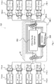
- Fig. 1 illustrates a communication system overview, which will be used subsequently to further detail and explain some embodiments.
- Fig. 1 shows a signal processing chain of a communication system 100, e.g., an optical communication system, which can also be provided by embodiments.
- the signal processing exemplarily starts at the upper left corner of Fig. 1 with an outer encoder 102, which may, for example, correspond to a convolutional encoder, a Reed Solomon encoder, or a Turbo product encoder 102.
- the task of the outer encoder 102 is to add redundancy to an input information word 101, which may comprise digitized data.
- a signal output 103 of the outer encoder 102 may then be input into an interleaver 104, which interleaves the data.
- the interleaving can be adapted to an error characteristic, which is introduced in a transmission channel 114 later on such that burst errors can be resolved by subsequent de-interleaving 124 to enable enhanced error correction at an outer decoder 126.
- resulting interleaved data 105 may then be input into an LDPC encoder 106 to obtain (encoded) LPDC code words 107 before being assigned to transmission symbols 109 by a mapping entity 108.
- the transmission symbols 109 may then be differentially encoded by a differential encoder 110 to prevent or limit the effect of phase slips, which may occur due to undetectable phase noise events in the subsequent transmission channel 114.
- phase slips do not occur in the transmission channel as such but are due to phase noise events that cause a phase offset correction algorithm to make a wrong decision.
- the phase noise correction algorithm is part of the digital signal processing chain that is not explicitly shown in Fig. 1 and that can be considered as being either part of the transmission channel 114 or as being part of the demodulation 116.
- Differentially encoded data symbols 111 may be derived, using a linear feedback shift register which comprises a delay element.
- the differentially encoded transmission symbols 111 are then modulated by modulator 112 and transmitted through the transmission channel 114. Note that the blocks 102 to 112 make up a transmitter of the communication system 100. This can be an optical transmitter.
- the modulation 112 may comprise a conversion from base band, which can be complex, to a transmission band as well as a conversion from a digital/electrical to an optical signal.
- a transmission channel e.g., an optical, a wireless, a wireline or a powerline transmission channel
- phase slips can occur due to the inability of a receiver to handle large phase noise, i.e., the phase may jump or suddenly change by a certain angle. This angle may correspond to 180° or ⁇ in a BPSK case; it may correspond predominantly to 90° or ⁇ /2 in the QPSK case. Such a phase slip may result in erroneous symbols being detected subsequently.
- the differential coding 110 limits the effect of a phase slip to the symbol, which is detected subsequent to the phase slip, as the difference to the previous symbol only is affected by the phase slip. However, since the difference to the next symbol is not affected by the phase slip (assuming only a single phase slip to occur), the differential encoding limits the effect of a phase slip. As the phenomenon of phase slips is well known in the art further details will be omitted not to obscure the principles of embodiments.
- Fig. 2 shows an equivalent channel model with BPSK mapping phase and 180° phase slips.
- Binary symbols x ⁇ ⁇ -1, +1 ⁇ are transmitted via the channel 114 and are affected by additive noise n, 115.
- the phase slips are rare and their probability of occurrence is low.
- the received differentially encoded data symbols may be demodulated 116, where the demodulation 116 may include optical/electrical conversion and conversion from the transmission band to the complex base band.
- Fig. 1 illustrates a processing path between the demodulation 116 and a subsequent de-interleaver 124 involving a differential decoder 118, an optional clipping function 120 and an LDPC decoder 122.
- the base band symbols may be differentially decoded 118, which may result in soft information 119, i.e., information on estimated symbols or bits and reliability information thereon, which can, for example, be expressed in terms of likelihood values or log-likelihood values.
- This soft information 119 from the differential decoder 118 may also be denoted as extrinsic probability information.
- a clipping function 120 may be applied to the output of the differential encoder.
- the clipping function 120 limits the likelihood values (extrinsic probability information) to enable a better decoding performance of the subsequent LDPC decoder 122.
- the performance of the LDPC decoder 122 can be improved by the limitation as an upper limit of the likelihood values can be assumed based on a known occurrence or probability of occurrence of a phase slip. For example, the probability of a phase slip for a given optical channel may be in a range around 10 -3 .
- all likelihood values can be limited to 10g((1-10 -3 )/10 -3 ) ⁇ 6.91, as this is the highest certainty that can be achieved.
- a residual error rate of 10 -3 is known and considered by using an according the clipping function 120.
- the clipped output 121 of the clipping function 120 may then be input into the LDPC decoder 122, which will be explained in more detail below.
- the LDPC decoder 122 may then determine updated likelihood values 121', which may be fed back to the clipping function 120 and from there to the differential decoder 118 as priori probability information 119' for a next iteration of differential decoder 118, which is indicated by the arrows between the differential decoder 118, the clipping function 120, and the LDPC decoder 122.
- the circular shaped arrows indicate that a number of iterations may be carried out, wherein the likelihood values are updated by one of the decoders 118, 122 and clipped in between by the clipping function 120.
- the decoding iteration may be terminated by a parity check criterion.
- the output from the LDPC decoder 122 may then be de-interleaved by de-interleaver 124 before being provided to the outer decoder 126 for outer decoding in line with the above described outer encoding 102.
- An LDPC code may be defined by a sparse binary parity check matrix H of dimension M ⁇ N, where N is the LDPC code word length (in bits) of the LDPC code and M denotes the number of parity bits.
- the rows of a parity check matrix are parity checks on the code words of a code. That is, they show how linear combinations of certain digits of each code word equal zero.
- the number of information bits equals M-N.
- Sparse means that the number of 1s in H is small compared to the number of zero entries.
- Practical LDPC codes usually have a fraction of "1s" that is below 1% by several orders of magnitude.
- Each column of the parity check matrix H corresponds to one bit of a Forward Error Correction (FEC) frame or LPDC code word.
- FEC Forward Error Correction
- LPDC code word LPDC code word
- each row of H corresponds to a parity check equation and ideally defines a parity bit, if H has full rank.
- the rank can be defined as the column rank.
- the column rank of a matrix H is the maximum number of linearly independent column vectors of H.
- row rank of H is the maximum number of linearly independent row vectors of H. Owing to the Tanner graph representation, the rows of H are associated to so-called check nodes. Note that the row rank and the column rank of a matrix H are always equal, which is a well-known result in linear algebra.
- y i the single bits of the code word y.
- AWGN Additive White Gaussian Noise
- LLR Log-Likelihood Ratio
- y i 0 p z i
- y i 1 with p z i
- L c 2/ ⁇ 2 is assumed to be constant and predetermined.
- LDPC decoder continuously updates the received LLR values with the goal to compute LLRs that approximate the Maximum A Posteriori (MAP) values.
- MAP Maximum A Posteriori
- the decoding operation in the row-layered decoder 122 comprises three acts, where a) the first act prepares the input data, b) the second act performs the computation of new extrinsic data and c) the final act updates the LLR memory.
- the row-layered LDPC decoder 122 carries out the three steps sequentially for each row of the parity check matrix H. After all rows have been considered, a single decoding iteration has been carried out.
- the LDPC decoder usually carries out several iterations, where the number depends on the available resources.
- the superscript ( l ) denotes the iteration counter, i.e., the operations are carried out in the l -th iteration of the row-layered LDPC decoding procedure.
- the value e m , i is the (stored) extrinsic memory for row m and variable ⁇ i .
- the log-domain expression may be more suitable for practical implementations, as the multiplication is replaced by an addition and instead of two functions tanh( ⁇ )/tanh -1 ( ⁇ ), only a single function ⁇ ( ⁇ ) needs to be implemented (or approximated by a look-up table).
- N m ⁇ i The product (or the sum) of equation (3) may be carried out over all entries in ( m ) except the one under consideration i. This is indicated by the notation N m ⁇ i .
- N 5 1 ; 5 ; 9 ; 13 ; 21
- Equation (4) for the extrinsic update is beyond the scope of this specification.
- e m , i can be further simplified.
- An often employed simplification of the log-domain equation (3), which we will consider in the following, is the so-called min-sum approximation which leads to e m , i l + 1 ⁇ j ⁇ N m ⁇ i sign t k , j min j ⁇ N m ⁇ i
- Fig. 3 shows the simplified block diagram 300 of the check node decoding operation for computing e m , i l + 1 .
- the check node operation 302 may be realized by equations (3) (log-domain) or (5) (min-sum domain).
- the update act c) can be further simplified in actual implementations.
- ⁇ m 1 min j ⁇ N m
- be the first minimum of the absolute value of all involved incoming messages t m , j at row m and let i m 1 arg min j ⁇ N m
- ⁇ m 2 min j ⁇ N m ⁇ i m 1
- one burden for implementing the check node operation 302 for computing e m , i l + 1 consists in finding the first and second minimum of the incoming messages together with the position of the first minimum.
- the memory requirements of this algorithm are N memory cells for storing the (continuously updated) a-posteriori values ⁇ i .
- the storing requirements of the extrinsic memory e m,i 304 amount to the total number of 1s in the parity check matrix H, however, due to the simplified implementation using the minimum approximation, the extrinsic memory 304 does not need to store all d c different values per row, but only the d c different signs, both minima ⁇ m 1 and ⁇ m 2 , and the location index of the first minimum i m 1 .
- the values e m , i can then be computed on the fly as required.
- FIG. 4 A simplified row-layered decoder block diagram 400, which can be derived from Fig. 3 in a straight forward way, is shown in Fig. 4 .
- the LDPC decoder 122 can iteratively invoke the soft-input soft-output differential detector 118 as, e.g., described in EP 2 538 596 A1 or EP 2 506 516 A1 . If a row-layered LDPC decoder is used, this has some implications on the architecture.
- the differential detector 118 may be implemented using the BCJR algorithm operating on a trellis diagram, see L. R. Bahl, J. Cocke, F. Jelinek, and J. Raviv, "Optimal Decoding of Linear Codes for minimizing symbol error rate", IEEE Transactions on Information Theory, vol. IT-20(2), pp.284-287, March 1974 .
- LDPC codes In the case of LDPC codes, easy decoding algorithms exist and in contrast to classical channel coding, the challenge is not to find a good decoder for a given code, but to find a good code given the decoding algorithm.
- Most LDPC codes that are implemented today are so-called Quasi-Cyclic (QC) LDPC codes. They have a parity check matrix H with a structure that allows for inherent parallelization of the LDPC decoder and leads to an efficient encoder realization. Almost all LDPC codes utilized in practice belong to the class of QC LDPC codes.
- QC-LDPC codes may be constructed using a so-called lifting matrix A.
- the parity check matrix H may be constructed from the lifting matrix A by replacing each element of A with either an all-zero matrix of size S ⁇ S or a permutation matrix, e.g., a cyclically permuted identity matrix, of size S ⁇ S.
- S denotes the lifting factor, i.e., the size of the all-zero or cyclically shifted identity matrix.
- A is sparse, i.e., most entries of A are, e.g., -1, leading to zero entries for H.
- the 1s of H are shown as small points. Due to the cyclic structure of the matrix H, these show up as diagonal lines in Fig.6 .
- a row-layered LDPC decoder 122 can now process always S rows of H in parallel as these computations are independent. This parallelism is necessary to be able to operate at decoding speeds of 100Gbit/s and above. Instead of decoding each row of H, the row-layered decoder 122 for QC LDPC codes does now decode each row of the lifting matrix A by decoding S rows of H in parallel.
- the decoding circuitry set up for decoding the first row of A of the example above is shown in Fig. 7 .
- the first row of A contains only 4 non-void entries ( A m,i ⁇ 0, as does any other row), which means that each of the first 5 rows of H contains only 4 ones.
- a 1,5 2
- the shifter 715-4 is configured such that it performs a (cyclic) left-shift by "2" and the output of the shifter 715-4 is the vector ( ⁇ 23 ⁇ 24 ⁇ 25 ⁇ 21 ⁇ 22 ) T .
- Embodiments of the present invention suggest a novel LDPC code design which also leads to fulfilled parity check equations for LDPC code word y' affected by a phase slip.
- an LDPC encoder which is operable or configured to provide an LDPC encoded signal based on an LDPC encoding rule corresponding to an M' ⁇ S ⁇ N' ⁇ S parity check matrix H' which comprises a plurality of S ⁇ S permutation (e.g., circulant) sub-matrices with an even number of non-zero entries in each row (and thus, consequently, also with an even number of non-zero entries in each column) of a sub-matrix.
- S ⁇ S permutation e.g., circulant
- the non-zero entries may be defined over the binary field F 2 or over the ring of integer numbers modulo 4.
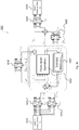
- This LDPC encoder may be concatenated with a differential encoder, wherein the differential decoder is located upstream to (i.e., before) the LDPC encoder - in contrast to Fig. 1 , where the differential decoder is located downstream to (i.e., after) the LDPC encoder. This will be explained in more detail with reference to Fig. 8 .
- a parity check matrix H' of a QCQS LDPC code may be obtained by adding parity check matrices H 1 and H 2 of two or more (an even number of) quasi-cyclic LDPC codes obtained based on associated two or more (an even number of) lifting matrices A 1 and A 2 . That is to say, the parity check matrix H' may correspond to an addition of an even number of parity check matrices corresponding to different quasi-cyclic LDPC codes, respectively.
- a first M'S ⁇ N'S parity check matrix H 1 of the even number of parity check matrices may be constructed from a first M' ⁇ N' lifting matrix A 1 by replacing each entry of the first lifting matrix A 1 with either an all-zero matrix of size S ⁇ S or a permutation matrix, e.g., a cyclically permuted identity matrix, of size S ⁇ S, depending on the entry of the first lifting matrix A 1 .
- a second M'S ⁇ N'S parity check matrix H 2 of the even number of parity check matrices may be constructed from a second M' ⁇ N' lifting matrix A 2 by replacing each entry of the second lifting matrix A 2 with either an all-zero matrix of size S ⁇ S or a permutation matrix, e.g., a cyclically permuted identity matrix, of size S ⁇ S, depending on the entry of the second lifting matrix A 2 .
- a m,i -1
- a 1, m , i may be smaller than A 2, m , i if A 1, m , i ⁇ x .
- the resulting parity check matrix H' has a dimension of M' ⁇ S ⁇ N' ⁇ S and comprises, besides a few S ⁇ S all-zero matrices (corresponding to the "-1" positions of the lifting matrices), a plurality of S ⁇ S permutation or circulant sub-matrices with two non-zero entries (e.g., ones) in each row of each S ⁇ S non-zero sub-matrix.
- each non-zero matrix is an S ⁇ S circulant sub-matrix with two non-zero entries (e.g., ones) in each row of each S ⁇ S non-zero sub-matrix.
- S 5 in the above example. Note that embodiments also allow four, six, eight, etc., non-zero entries (e.g., ones) in each row of each S ⁇ S non-zero sub-matrix.
- QQS LDPC Quasi-Cyclic, Quasi-Symmetric Low-Density Parity-Check (QCQS LDPC) code
- QQS LDPC Quasi-Symmetric Low-Density Parity-Check
- Hx T 0 ⁇ be the code.
- a differential encoder 810 which is configured to provide a differentially encoded signal 811 based on an input signal 105 and based on a differential encoding rule.
- the differential encoder 810 can be a plain bit differential encoder making a current bit to depend on a previous bit or a block differential encoder making a current block of bits to depend on a previous block of bits, resulting in a lower complexity.
- the encoder 830 comprises an LDPC encoder 806 which is configured to provide an LDPC encoded signal 807 based on the differentially encoded signal 811 and based on an LDPC encoding rule defined by or corresponding to an M'S ⁇ N'S parity check matrix H' comprising a plurality of S ⁇ S permutation or circulant sub-matrices with an even number of non-zero entries in each row of a sub-matrix.
- the LDPC decoding rule may be kept transparent to phase slips caused by noise of a transmission channel for the LDPC encoded signal.
- some embodiments provide a decoder 840 comprising an LDPC decoder 822 which is configured to provide an output signal 823 based on an input signal 821 and based on an LDPC decoding rule defined by or corresponding to an M'S ⁇ N'S parity check matrix H' comprising a plurality of S ⁇ S permutation or circulant sub-matrices with an even number of non-zero entries in each row of an S ⁇ S sub-matrix.
- the decoder 840 comprises a differential decoder 818 which is configured to provide a decoded signal 819 based on the output signal 823 from the LDPC decoder 822 and based on a differential decoding rule corresponding to the differential encoding rule.
- the encoder 830 and/or decoder 840 may be comprised by an optical communication system 800 for transmitting optical signals.
- an optical communication system 800 for transmitting optical signals.
- other applications such as in wireless communications, are also possible. Therefore embodiments are not restricted to the exemplary setup shown in Fig. 8 . In fact, other hard- and/or software combinations are possible.
- exemplary LDPC code constructions may lead to rank-deficient LDPC parity check matrices H'.
- M' linearly dependent parity check equations if we consider the S parity check equations corresponding to one line (row) of A i , we see that the rank of that sub-matrix is upper bounded by S -1).
- the total or combined parity check matrix H' is rank-deficient with rank( H' ) ⁇ M '( S -1).
- M' are linearly dependent parity checks. This increase in coding rate may be avoided especially in optical communication systems, which already operate at very high rates close to the theoretical limits.
- Some embodiments therefore allow to construct LDPC codes without the described rank deficiency, i.e., with rank( H' ) ⁇ M 'S.
- rank( H' ) ⁇ M 'S rank( H' ) ⁇ M 'S.
- One possibility to get a full-rank LDPC parity check matrix is to have for instance in each chunk of S rows of H' one S ⁇ S sub-matrix which has an even number of additional non-zero entries, such that there are, e.g., 4 ones in this row of the S ⁇ S sub-matrix.
- Another possibility is to remove in each chunk of S rows of H' and in one row of one S ⁇ S sub-matrix of said chunk an even number of the non-zero entries.
- each chunk of S rows comprises one row with more or less non-void or non-zero entries than the other rows of said chunk, such that the parity check matrix H' has full rank.
- the resulting LDPC code is not quasi-cyclic (QC) anymore, but the quasi-symmetric (QS) property is maintained.
- An exemplary LDPC parity check matrix according to the first possibility i.e., each chunk of S rows comprises one row with more non-zero entries than the other rows of said chunk, is given by wherein the added 1s are given in a larger font size.
- An exemplary parity check matrix according to the second possibility i.e., each chunk of S rows comprises one row with less non-zero entries than the other rows of said chunk, is given by
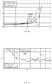
- the LDPC codes C 1 and C 2 have been combined with a bit differential code and with a block differential code, respectively.
- Fig. 9a that embodiments work especially well for phase slip probabilities ⁇ 10 -5 .
- we compare with a system of approximately identical decoding complexity which is composed of a simple differential decoder and an optimized LDPC code we can achieve a performance gain of about 1dB, see Fig. 9b .
- the outer code 102 is a 7% overhead code as specified in ITU-T, G.975.1 "Forward Error Correction for high bit-rate DWDM submarine systems", 2004, which requires an input BER of around 3 ⁇ 10 -3 to achieve near error-free decoding.
- the decoding operation in a row-layered LDPC decoder for QC-LDPC codes with a parity check matrix generated by a lifting operation from a lifting matrix A comprises three acts, where a first act a) prepares the input data, a second act b) performs the computation of new extrinsic data and a final act c) updates the LLR memory.
- the LDPC decoder carries out the three steps sequentially for each row of the LDPC parity check matrix. After all rows have been considered, a single decoding iteration has been carried out. The decoder usually carries out several iterations, where the number depends on the available resources.
- the function f shift,s ( z , A m,i ) returns the s -th entry after cyclically left-shifting the vector z by A m , i positions.
- the value e m,i,s denotes the (stored) extrinsic memory for row m of A and variable ⁇ i,s .
- Equation (17) denotes the aforementioned min-sum update. Note that there exist different varieties for this update equations, namely the sum-product rule, the box-plus update rule, the scaled min-sum update rule or the offset-corrected update rule, to name only a few. A comprehensive overview is given in W.E. Ryan and S. Lin, Channel Codes - Classical and Modern, Cambridge University Press, 2009 . As this second LDPC decoding act computes the output of the parity check node of the check node in the graphical representation of LDPC codes, it is frequently denoted by check node operation.
- Fig. 10 will be explained from left to right.
- a chunk of S consecutive a-posteriori LLRs may be fetched from the memory 1010 and, using the two shifts 1015-1, 1015-2 defined by the m -th row and the i -th column of A 1 and A 2 , accordingly rotated.
- the check node update may be computed using equation (17) or variants / approximations thereof.
- the computation of the a-posteriori update needs to be modified accordingly and we need to subtract from each of the S a-posteriori entries of the i -th chunk the two incoming extrinsic edge values corresponding to the content of the extrinsic memory e m,j,s .
- f shift e m ,2 i , S ⁇
- the LDPC decoder 822 is operable to perform iterative row-layered LDPC decoding, wherein the LDPC decoder 822 may be operable to update, per S ⁇ S sub-matrix, two (or an even number of) variable nodes associated to a non-zero entry with two (or an even number of) refined new extrinsic edge values.
- Quadrature Phase-Shift Keying QPSK
- 8-QAM 8-ary Quadrature Amplitude Modulation
- 16-QAM 16-QAM
- 32-QAM 32-QAM
- One particular format of interest for optical communication systems realizing 200 Gbit/s in a single channel with high reach is the 8-QAM format. With a transmitter operating at 38 GBaud (Giga symbols per second) and employing two polarizations, 228 Gbit/s gross data rate can be transmitted, which accounts for framing overhead and coding.
- 8-QAM formats exist, however, one particular format of interest is the format shown in Fig. 11 .
- This format or signal constellation has the appealing property that it only has a 180° phase ambiguity, i.e., only phase slips of 180° can occur, as in the BPSK case.
- we can employ a bit mapping as in Fig. 11 where the two Least Significant Bits (LSBs) of a 3-bit symbol are mapped in such a way that a 180° rotation of the symbol (a phase slip) does not affect the mapping of the two LSBs.
- MSB Most Significant Bit
- the entries of a predetermined portion or fraction b (e.g., 2/3) of the columns of the LDPC code's second lifting matrix A 2 correspond to x, wherein x (e.g., -1) denotes a predetermined value leading to void or zero entries in the corresponding or associated second parity check matrix H 2 .
- x e.g., -1
- H 1 + H 2 the quasi-symmetric code property.
- embodiments also comprise code designs defined by an M'S ⁇ N'S parity check matrix H' which comprises a plurality of S ⁇ S permutation or circulant sub-matrices with an even number of non-zero entries in each row of an S ⁇ S sub-matrix, wherein the plurality of S ⁇ S permutation or circulant sub-matrices forms a portion or fraction of the N'S columns of H' corresponding to a fraction of bits (of a multiple bit symbol) to be protected against phase slips by the LPDC code.
- H' M'S ⁇ N'S parity check matrix
- the right-most part of the above exemplary matrix H' (not fulfilling the quasi-symmetric property), i.e., the rightmost 20 columns in the example above, has an odd number of ones per row (if the first third of the code is assumed to be set to zero) of the sub-matrix, such that this sub-code is asymmetric, see A. Scherb and K.-D. Kammeyer, "Non-coherent LDPC decoding on graphs", Proc. IEEE Information Theory Workshop (ITW), Chengdu, China, Oct. 2006 , and that the data can be resolved without ambiguity.
- the number of ones per row in the rightmost 20 columns of H' (the columns not fulfilling the quasi-symmetric properties) amounts to 3.
- embodiments also comprise code designs defined by an M'S ⁇ N'S parity check matrix H' comprising a first fraction of S ⁇ S permutation or circulant sub-matrices with an even number of non-zero entries in each row of a sub-matrix and comprising a second fraction of S ⁇ S permutation sub-matrices with an odd number of non-zero entries in each row of a sub-matrix, wherein the first fraction of permutation or circulant S ⁇ S sub-matrices may form a first contiguous fraction of the N'S columns of H' corresponding to a fraction of bits (of a multiple bit symbol) to be protected against phase slips by the LPDC code, and wherein the second fraction of sub-matrices forms a second fraction (e.g., the rest) of the N'S columns corresponding to a second fraction (e.g., the rest) of bits of the multiple bit symbol.
- H' parity check matrix
- the second fraction may be obtained by subtracting the first fraction from one.
- the fraction of the columns need not be contiguous but can be arranged in an arbitrary manner, if the interleaver is properly designed. However, by column rearrangement (and consequently re-design of the interleaver), the matrix can always be brought into a form where the columns are contiguous.
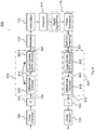
- the outer encoded and interleaved data 105 is de-multiplexed or parallelized by de-multiplexer 1231 to obtain a plurality of parallel bits (e.g., three in the 8-QAM case) per symbol.
- One or more bits to be especially protected against phase slips may be differentially encoded by differential encoder 810 before the non-differentially-encoded and differentially encoded bits are multiplexed or serialized again by multiplexer 1232 in such a way that the bits to be protected against phase slips are mapped to those columns of the parity check matrix that correspond to the first fraction of permutation or circulant S ⁇ S sub-matrices with an even number of non-zero entries in each row of a sub-matrix.
- the resulting data stream 1233 is the fed into a QS-LDPC encoder 806 according to an embodiment, which operates according to an LDPC encoding rule that is defined by or based on an M'S ⁇ N'S parity check matrix H' comprising a plurality of permutation or circulant S ⁇ S sub-matrices with an even number of non-zero entries in each row of an S ⁇ S sub-matrix, wherein the plurality of permutation or circulant S ⁇ S sub-matrices forms a fraction of the N'S columns corresponding to the fraction of differentially encoded bits (of a multiple bit symbol) to be especially protected against phase slips by the LPDC code.
- an LDPC encoding rule that is defined by or based on an M'S ⁇ N'S parity check matrix H' comprising a plurality of permutation or circulant S ⁇ S sub-matrices with an even number of non-zero entries in each row of an S ⁇ S sub-matrix,
- the resulting bit stream may then be fed to interleaver ⁇ M 1235, which interleaves the bits located on the fraction of bit positions corresponding to the differentially encoded bits, for example. In the illustrated case of 8-QAM this may be the MSB bit positions, respectively. Subsequently, 8-QAM bit-to-symbol mapping 1208 may take place.
- the receiver side of the communication system 1200 carries out the respective inverse operations, i.e., de-mapping 1236, de-interleaving ⁇ M -1 1238, LDPC decoding 822, demultiplexing 1231, differential decoding 818, multiplexing 1232, de-interleaving 124, and outer decoding 126.
- the QS LDPC decoder 822 may operate according to an LDPC decoding rule defined by or based on an M'S ⁇ N'S parity check matrix H' comprising a plurality of permutation or circulant S ⁇ S sub-matrices with an even number of non-zero entries in each row of an S ⁇ S sub-matrix, wherein the plurality of permutation or circulant S ⁇ S sub-matrices forms a contiguous fraction (e.g., 1/3) of the N'S columns corresponding to the fraction of differentially encoded bits (of a multiple bit symbol) to be especially protected against phase slips by the LPDC code.
- contiguous means that the columns comprised by the fraction or portion are contiguously adjacent.
- a QS LDPC code may not be defined over the binary field F 2 but over the ring of integer numbers modulo 4, also called Z 4 .
- the M'S ⁇ N'S parity check matrix H' comprises a plurality of permutation or circulant (non-zero) S ⁇ S sub-matrices with an even number of non-zero entries in each row of each S ⁇ S sub-matrix, wherein the non-zero entries can be from the ring of integer numbers modulo 4.
- the decoding 822 may be performed using a non-binary LDPC decoder, as described in H. Wymeersch, H. Steendam, M. Moeneclaey, "Log-Domain Decoding of LDPC codes over GF(q)", IEEE Conf. on Communications (ICC), 2004 , where we can also employ a column- or row-layered design and the aforementioned modifications to it.
- the differential decoder 818 in Fig. 8 may be modified accordingly to a QPSK or higher order decoder.
- the partially quasi-symmetric code of the previous section to be used with the 8-QAM modulation format can be modified accordingly to be able to work with higher order modulation formats with 90° phase ambiguity, e.g., the square 16-QAM format.
- Functional blocks shall be understood as functional blocks comprising circuitry that is adapted for performing a certain function, respectively.
- a "means for s.th.” may as well be understood as a “means being adapted or suited for s.th.”.
- a means being adapted for performing a certain function does, hence, not imply that such means necessarily is performing said function (at a given time instant).
- any functional blocks may be provided through the use of dedicated hardware, such as “a processor”, “a controller”, etc. as well as hardware capable of executing software in association with appropriate software.
- any entity described herein as functional block may correspond to or be implemented as "one or more modules", “one or more devices”, “one or more units”, etc.
- the functions may be provided by a single dedicated processor, by a single shared processor, or by a plurality of individual processors, some of which may be shared.
- processor or “controller” should not be construed to refer exclusively to hardware capable of executing software, and may implicitly include, without limitation, digital signal processor (DSP) hardware, network processor, application specific integrated circuit (ASIC), field programmable gate array (FPGA), read only memory (ROM) for storing software, random access memory (RAM), and non-volatile storage.
- DSP digital signal processor
- ASIC application specific integrated circuit
- FPGA field programmable gate array
- ROM read only memory
- RAM random access memory
- non-volatile storage Other hardware, conventional and/or custom, may also be included.
- any block diagrams herein represent conceptual views of illustrative circuitry embodying the principles of the invention.
- any flow charts, flow diagrams, state transition diagrams, pseudo code, and the like represent various processes which may be substantially represented in computer readable medium and so executed by a computer or processor, whether or not such computer or processor is explicitly shown.
- each claim may stand on its own as a separate embodiment. While each claim may stand on its own as a separate embodiment, it is to be noted that - although a dependent claim may refer in the claims to a specific combination with one or more other claims - other embodiments may also include a combination of the dependent claim with the subject matter of each other dependent claim. Such combinations are proposed herein unless it is stated that a specific combination is not intended. Furthermore, it is intended to include also features of a claim to any other independent claim even if this claim is not directly made dependent to the independent claim.
- a single step may include or may be broken into multiple sub steps. Such sub steps may be included and part of the disclosure of this single step unless explicitly excluded.
Landscapes
- Physics & Mathematics (AREA)
- Engineering & Computer Science (AREA)
- Mathematical Physics (AREA)
- Probability & Statistics with Applications (AREA)
- Theoretical Computer Science (AREA)
- General Physics & Mathematics (AREA)
- Computational Mathematics (AREA)
- Mathematical Analysis (AREA)
- Mathematical Optimization (AREA)
- Pure & Applied Mathematics (AREA)
- Computer Networks & Wireless Communication (AREA)
- Signal Processing (AREA)
- Algebra (AREA)
- Computing Systems (AREA)
- Error Detection And Correction (AREA)
Claims (15)
- Sender, umfassend:einen Codierer (830), umfassendeinen Differenzcodierer (810), der betriebsfähig ist, ein differenziell codiertes Signal (811) basierend auf einem Eingangssignal (105) und einer Differenzcodierregel bereitzustellen;einen LDPC-Codierer (806), der betriebsfähig ist, ein LDPC-codiertes Signal (807) basierend auf dem differenziell codierten Signal (811) und basierend auf einer LDPC-Codierregel entsprechend einer M'SxN'S-Paritätsprüfungsmatrix (H') bereitzustellen, umfassend eine Vielzahl von SxS-Permutationsuntermatrizen mit einer geraden Zahl von Nicht-Null-Einträgen in jeder Zeile einer SxS-Untermatrix; undeinen digitalen Modulator (112), der an einen Ausgang des LDPC-Codierers (806) gekoppelt und gemäß einem Konstellationsdiagramm betriebsfähig ist.
- Sender nach Anspruch 1, wobei die Nicht-Null-Einträge über das binäre Feld F2 oder über den Ring aus ganzen Zahlen Modulo 4 definiert werden.
- Sender nach Anspruch 1, wobei der Differenzcodierer als Bitdifferenzcodierer betriebsfähig ist, der ein aktuelles Bit von einem vorherigen Bit abhängig macht, oder als Blockdifferenzcodierer, der einen aktuellen Block von Bits von einem vorherigen Block von Bits abhängig macht.
- Sender nach Anspruch 1, wobei die LDPC-Codierregel für Phasengleiten transparent ist, das von einem Phasenrauschereignis verursacht wird, das das LDPC-codierte Signal beeinträchtigt.
- Sender nach Anspruch 1, wobei die Paritätsprüfungsmatrix (H') auf einer Addition einer geraden Zahl von Paritätsprüfungsmatrizen (H1 , H2 ) basiert, die jeweils unterschiedlichen quasizyklischen LDPC-Codes entsprechen.
- Sender nach Anspruch 5, wobei eine erste Paritätsprüfungsmatrix (H1 ) von der geraden Zahl von Paritätsprüfungsmatrizen (H1 , H2 ) aus einer ersten M'xN'-Lifting-Matrix (A1 ) konstruiert wird durch Ersetzen jedes Eintrags der ersten Lifting-Matrix (A1 ) entweder durch eine Nullmatrix der Größe SxS oder eine Permutationsmatrix der Größe SxS, je nach Eintrag der ersten Lifting-Matrix (A1 ), wobei eine zweite Paritätsprüfungsmatrix (H2 ) von der geraden Zahl von Paritätsprüfungsmatrizen (H1 , H2 ) aus einer zweiten M'xN'-Lifting-Matrix (A2 ) konstruiert wird durch Ersetzen jedes Eintrags der zweiten Lifting-Matrix (A2 ) entweder durch eine Nullmatrix der Größe SxS oder eine Permutationsmatrix der Größe SxS, je nach Eintrag der zweiten Lifting-Matrix (A2 ), wobei ein Eintrag A 1,m,i der m-ten Zeile und der i-ten Spalte der ersten Lifting-Matrix (A1 ) einem Eintrag A 2,m,i der m-ten Zeile und der i-ten Spalte der zweiten Lifting-Matrix (A2 ) entspricht, wenn der Eintrag A 1,m, i x ist, wobei x einen vorbestimmten Wert der ersten Lifting-Matrix (A1 ) bezeichnet, der zu null Einträgen in der entsprechenden ersten Paritätsprüfungsmatrix (H1 ) führt, und wobei ein Eintrag A 1,m,i ≠ A 2,m,i ≠ x wenn A 1,m,i ≠ x.
- Sender nach Anspruch 1, wobei die Paritätsprüfungsmatrix (H') M' Blöcke von S Zeilen umfasst, wobei M' eine Zahl von Zeilen einer Lifting-Matrix (A1 , A2 ) bezeichnet, wobei jeder Block eine Zeile mit mehr oder weniger Nicht-Null-Einträgen als die anderen Zeilen des besagten Blocks umfasst, so dass die Paritätsprüfungsmatrix (H') vollen Rang hat.
- Sender nach Anspruch 6, wobei Einträge eines vorbestimmten Teils von Spalten der zweiten Lifting-Matrix (A2 ) x entsprechen, wobei x einen vorbestimmten Wert bezeichnet, der zu null Einträgen in der entsprechenden zweiten Paritätsprüfungsmatrix (H2 ) führt.
- Verfahren zur Übertragung eines Signals, umfassend:differenzielles Codieren eines Eingangssignals (105) basierend auf einer Differenzcodierregel, um ein differenziell codiertes Signal (811) zu erhalten;LDPC-Codieren des differenziell codierten Signals (811), basierend auf einer LDPC-Codierregel entsprechend einer M'SxN'S-Paritätsprüfungsmatrix (H'), umfassend eine Vielzahl von SxS-Permutationsuntermatrizen mit einer geraden Zahl von Nicht-Null-Einträgen in jeder Zeile einer SxS-Untermatrix; undModulieren des LDPC-codierten Signals (807) gemäß einem Konstellationsdiagramm.
- Empfänger, umfassend:einen digitalen Demodulator (116), der betriebsfähig ist, ein empfangenes Signal basierend auf einem Konstellationsdiagramm zu demodulieren, um ein Eingangssignal zu erhalten;einen Decodierer (840), umfassend:einen LDPC-Decodierer (822), der betriebsfähig ist, ein Ausgangssignal (823) basierend auf dem Eingangssignal (821) und basierend auf einer LDPC-Decodierregel entsprechend einer M'SxN'S-Paritätsprüfungsmatrix (H') bereitzustellen, umfassend eine Vielzahl von SxS-Permutationsuntermatrizen mit einer geraden Zahl von Nicht-Null-Einträgen in jeder Zeile einer SxS-Untermatrix; undeinen Differenzdecodierer (818), der betriebsfähig ist, ein decodiertes Signal (819) basierend auf dem Ausgangssignal (823) von dem LDPC-Decodierer (822) und einer Differenzdecodierregel bereitzustellen.
- Empfänger nach Anspruch 10, wobei die Paritätsprüfungsmatrix (H') einer Addition einer geraden Zahl von Paritätsprüfungsmatrizen (H1 , H2 ) entspricht, die jeweils unterschiedlichen quasizyklischen LDPC-Codes entsprechen.
- Empfänger nach Anspruch 11, wobei eine erste Paritätsprüfungsmatrix (H1 ) von der geraden Zahl von Paritätsprüfungsmatrizen (H1 , H2 ) aus einer ersten Lifting-Matrix (A1 ) konstruiert wird durch Ersetzen jedes Eintrags der ersten Lifting-Matrix (A1 ) entweder durch eine Nullmatrix der Größe SxS oder eine Permutationsmatrix der Größe SxS, je nach Eintrag der ersten Lifting-Matrix (A1 ), wobei eine zweite Paritätsprüfungsmatrix (H2 ) von der geraden Zahl von Paritätsprüfungsmatrizen (H1 , H2 ) aus einer zweiten Lifting-Matrix (A2 ) konstruiert wird durch Ersetzen jedes Eintrags der zweiten Lifting-Matrix (A2 ) entweder durch eine Nullmatrix der Größe SxS oder eine Permutationsmatrix der Größe SxS, je nach Eintrag der zweiten Lifting-Matrix (A2 ), wobei ein Eintrag A 1,m,i der m-ten Zeile und der i-ten Spalte der ersten Lifting-Matrix (A1 ) einem Eintrag A 2,m,i der m-ten Zeile und der i-ten Spalte der zweiten Lifting-Matrix (A2 ) entspricht, wenn der Eintrag A1,m,i x ist, wobei x einen vorbestimmten Wert der ersten Lifting-Matrix (A1 ) bezeichnet, der zu null Einträgen in der entsprechenden ersten Paritätsprüfungsmatrix (H1 ) führt, und wobei ein Eintrag A1,m,i ≠ A 2,m,i ≠ x wenn A 1,m, i ≠ x.
- Empfänger nach Anspruch 10, wobei der LDPC-Decodierer betriebsfähig ist, eine iterative zeilenweise LDPC-Decodierung durchzuführen, wobei der LDPC-Decodierer betriebsfähig ist, pro SxS-Untermatrix, einen variablen Knoten, der zu einem Nicht-Null-Eintrag zugehörig ist, zwei Mal pro Iteration zu aktualisieren.
- Verfahren zum Empfangen eines Signals, umfassend:digitales Demodulieren des empfangenen Signals basierend auf einem Konstellationsdiagramm, um ein Eingangssignal zu erhalten;LDPC-Decodieren des Eingangssignals zum Bereitstellen eines Ausgangssignals basierend auf dem Eingangssignal und auf einer LDPC-Decodierregel entsprechend einer Paritätsprüfungsmatrix (H'), umfassend eine Vielzahl von SxS-Permutationsuntermatrizen mit einer geraden Zahl von Nicht-Null-Einträgen in jeder Zeile einer SxS-Untermatrix; unddifferenzielles Decodieren des Ausgangssignals zum Bereitstellen eines decodierten Signals basierend auf dem Ausgangssignal von dem LDPC-Decodierer und einer Differenzdecodierregel.
- Computerprogramm mit einem Programmcode zum Durchführen des Verfahrens nach Anspruch 9 oder Anspruch 14, wenn das Computerprogramm auf einer programmierbaren Hardwarevorrichtung ausgeführt wird.
Priority Applications (1)
| Application Number | Priority Date | Filing Date | Title |
|---|---|---|---|
| EP13306105.1A EP2833554B8 (de) | 2013-07-31 | 2013-07-31 | Kodierer und Dekodierer |
Applications Claiming Priority (1)
| Application Number | Priority Date | Filing Date | Title |
|---|---|---|---|
| EP13306105.1A EP2833554B8 (de) | 2013-07-31 | 2013-07-31 | Kodierer und Dekodierer |
Publications (3)
| Publication Number | Publication Date |
|---|---|
| EP2833554A1 EP2833554A1 (de) | 2015-02-04 |
| EP2833554B1 true EP2833554B1 (de) | 2018-03-28 |
| EP2833554B8 EP2833554B8 (de) | 2018-06-06 |
Family
ID=48985706
Family Applications (1)
| Application Number | Title | Priority Date | Filing Date |
|---|---|---|---|
| EP13306105.1A Active EP2833554B8 (de) | 2013-07-31 | 2013-07-31 | Kodierer und Dekodierer |
Country Status (1)
| Country | Link |
|---|---|
| EP (1) | EP2833554B8 (de) |
Families Citing this family (2)
| Publication number | Priority date | Publication date | Assignee | Title |
|---|---|---|---|---|
| CN110677159B (zh) * | 2019-11-13 | 2023-03-10 | 天津津航计算技术研究所 | Ldpc校验矩阵的四环快速检测方法 |
| CN117879620B (zh) * | 2024-03-13 | 2024-07-05 | 荣耀终端有限公司 | 译码方法、可读存储介质、程序产品及电子设备 |
Family Cites Families (4)
| Publication number | Priority date | Publication date | Assignee | Title |
|---|---|---|---|---|
| WO2006055086A1 (en) * | 2004-10-01 | 2006-05-26 | Thomson Licensing | A low density parity check (ldpc) decoder |
| JP4487213B2 (ja) * | 2007-10-19 | 2010-06-23 | ソニー株式会社 | 復号装置および方法、並びにプログラム |
| EP2506516A1 (de) | 2011-03-31 | 2012-10-03 | Alcatel Lucent | Verfahren zur Dekodierung optischer Datensignale |
| EP2538596B1 (de) | 2011-06-21 | 2014-05-14 | Alcatel Lucent | Verfahren zur Decodierung eines unterschiedlich codierten, phasenmodulierten optischen Datensignals |
-
2013
- 2013-07-31 EP EP13306105.1A patent/EP2833554B8/de active Active
Non-Patent Citations (1)
| Title |
|---|
| None * |
Also Published As
| Publication number | Publication date |
|---|---|
| EP2833554A1 (de) | 2015-02-04 |
| EP2833554B8 (de) | 2018-06-06 |
Similar Documents
| Publication | Publication Date | Title |
|---|---|---|
| US8595585B2 (en) | Reverse concatenated encoding and decoding | |
| EP2833553B1 (de) | LDPC-Decodierer | |
| CA2915740C (en) | Method and apparatus for encoding and decoding low density parity check codes | |
| EP2879295B1 (de) | Sendeverfahren, empfangsverfahren, sender und empfänger | |
| EP2012433A2 (de) | LDPC- (Low Density Parity Check-) Dekodierer mit verteilter Verarbeitung | |
| EP2525497A1 (de) | Bitverschachtelte Codierte Modulation (BICM) mit quasi-zyklischen LDPC Codes | |
| EP1909394A2 (de) | LDPC- (Low Density Parity Check-) Dekodierer auf der Basis überlappender Untermatrizen | |
| US8880973B1 (en) | Detector-decoder interface for GF(q) iterative decoding | |
| EP2892157A1 (de) | Offset Min-Sum Decodierung von LDPC Codes | |
| EP3293885B1 (de) | Prüfknotenberarbeitung zur syndromberechnung in der decodierung nicht binärer codes, insbesondere nicht binärer ldpc codes | |
| US20090013239A1 (en) | LDPC (Low Density Parity Check) decoder employing distributed check and/or variable node architecture | |
| EP3316486B1 (de) | Decodierung mit elementaren prüfknoten zur syndromberechnung mit vorsortierung der eingänge | |
| EP2890016A1 (de) | LDPC-Codierer und -Decodierer | |
| WO2009153746A2 (en) | Node information storage method and system for a low-density parity-check decoder | |
| KR102616481B1 (ko) | 수신 장치 및 그의 신호 처리 방법 | |
| EP3046259A1 (de) | Vorrichtungen und Verfahren zur LDPC-Faltungscodierung und -decodierung | |
| KR102075946B1 (ko) | 비이진 패리티 검사 부호의 복호 방법 및 장치 | |
| EP2833554B1 (de) | Kodierer und Dekodierer | |
| EP2911304A1 (de) | Sliding Window Decodierung für LDPC Faltungscodes (LDPC-CC) | |
| EP3001571A1 (de) | LDPC Codierung und Decodierung für Kanäle mit Phasenverschiebung | |
| EP2843844B1 (de) | Sender und Empfänger | |
| EP2639962B1 (de) | Gemeinsame Message-Passing Decodierung eines Differenzial- und eines Kanalcodes | |
| Schmalen | A low-complexity LDPC coding scheme for channels with phase slips | |
| Schmalen | Low-complexity phase slip tolerant LDPC-based FEC scheme | |
| EP3591845B1 (de) | Sortierungsvorrichtung und verfahren für elementare prüfknotenverarbeitung für message-passing decodierung von nichtbinären codes |
Legal Events
| Date | Code | Title | Description |
|---|---|---|---|
| 17P | Request for examination filed |
Effective date: 20140717 |
|
| AK | Designated contracting states |
Kind code of ref document: A1 Designated state(s): AL AT BE BG CH CY CZ DE DK EE ES FI FR GB GR HR HU IE IS IT LI LT LU LV MC MK MT NL NO PL PT RO RS SE SI SK SM TR |
|
| AX | Request for extension of the european patent |
Extension state: BA ME |
|
| PUAI | Public reference made under article 153(3) epc to a published international application that has entered the european phase |
Free format text: ORIGINAL CODE: 0009012 |
|
| RBV | Designated contracting states (corrected) |
Designated state(s): AL AT BE BG CH CY CZ DE DK EE ES FI FR GB GR HR HU IE IS IT LI LT LU LV MC MK MT NL NO PL PT RO RS SE SI SK SM TR |
|
| STAA | Information on the status of an ep patent application or granted ep patent |
Free format text: STATUS: EXAMINATION IS IN PROGRESS |
|
| 17Q | First examination report despatched |
Effective date: 20170801 |
|
| GRAP | Despatch of communication of intention to grant a patent |
Free format text: ORIGINAL CODE: EPIDOSNIGR1 |
|
| STAA | Information on the status of an ep patent application or granted ep patent |
Free format text: STATUS: GRANT OF PATENT IS INTENDED |
|
| INTG | Intention to grant announced |
Effective date: 20171102 |
|
| RIN1 | Information on inventor provided before grant (corrected) |
Inventor name: SCHMALEN, LAURENT Inventor name: PEPE, MARIANNA |
|
| GRAS | Grant fee paid |
Free format text: ORIGINAL CODE: EPIDOSNIGR3 |
|
| GRAA | (expected) grant |
Free format text: ORIGINAL CODE: 0009210 |
|
| STAA | Information on the status of an ep patent application or granted ep patent |
Free format text: STATUS: THE PATENT HAS BEEN GRANTED |
|
| AK | Designated contracting states |
Kind code of ref document: B1 Designated state(s): AL AT BE BG CH CY CZ DE DK EE ES FI FR GB GR HR HU IE IS IT LI LT LU LV MC MK MT NL NO PL PT RO RS SE SI SK SM TR |
|
| REG | Reference to a national code |
Ref country code: GB Ref legal event code: FG4D |
|
| REG | Reference to a national code |
Ref country code: CH Ref legal event code: EP |
|
| REG | Reference to a national code |
Ref country code: AT Ref legal event code: REF Ref document number: 984288 Country of ref document: AT Kind code of ref document: T Effective date: 20180415 |
|
| RAP2 | Party data changed (patent owner data changed or rights of a patent transferred) |
Owner name: ALCATEL LUCENT |
|
| REG | Reference to a national code |
Ref country code: IE Ref legal event code: FG4D |
|
| REG | Reference to a national code |
Ref country code: DE Ref legal event code: R096 Ref document number: 602013035014 Country of ref document: DE |
|
| REG | Reference to a national code |
Ref country code: FR Ref legal event code: PLFP Year of fee payment: 6 |
|
| PG25 | Lapsed in a contracting state [announced via postgrant information from national office to epo] |
Ref country code: HR Free format text: LAPSE BECAUSE OF FAILURE TO SUBMIT A TRANSLATION OF THE DESCRIPTION OR TO PAY THE FEE WITHIN THE PRESCRIBED TIME-LIMIT Effective date: 20180328 Ref country code: LT Free format text: LAPSE BECAUSE OF FAILURE TO SUBMIT A TRANSLATION OF THE DESCRIPTION OR TO PAY THE FEE WITHIN THE PRESCRIBED TIME-LIMIT Effective date: 20180328 Ref country code: FI Free format text: LAPSE BECAUSE OF FAILURE TO SUBMIT A TRANSLATION OF THE DESCRIPTION OR TO PAY THE FEE WITHIN THE PRESCRIBED TIME-LIMIT Effective date: 20180328 Ref country code: NO Free format text: LAPSE BECAUSE OF FAILURE TO SUBMIT A TRANSLATION OF THE DESCRIPTION OR TO PAY THE FEE WITHIN THE PRESCRIBED TIME-LIMIT Effective date: 20180628 |
|
| REG | Reference to a national code |
Ref country code: NL Ref legal event code: MP Effective date: 20180328 |
|
| REG | Reference to a national code |
Ref country code: LT Ref legal event code: MG4D |
|
| PG25 | Lapsed in a contracting state [announced via postgrant information from national office to epo] |
Ref country code: LV Free format text: LAPSE BECAUSE OF FAILURE TO SUBMIT A TRANSLATION OF THE DESCRIPTION OR TO PAY THE FEE WITHIN THE PRESCRIBED TIME-LIMIT Effective date: 20180328 Ref country code: SE Free format text: LAPSE BECAUSE OF FAILURE TO SUBMIT A TRANSLATION OF THE DESCRIPTION OR TO PAY THE FEE WITHIN THE PRESCRIBED TIME-LIMIT Effective date: 20180328 Ref country code: RS Free format text: LAPSE BECAUSE OF FAILURE TO SUBMIT A TRANSLATION OF THE DESCRIPTION OR TO PAY THE FEE WITHIN THE PRESCRIBED TIME-LIMIT Effective date: 20180328 Ref country code: BG Free format text: LAPSE BECAUSE OF FAILURE TO SUBMIT A TRANSLATION OF THE DESCRIPTION OR TO PAY THE FEE WITHIN THE PRESCRIBED TIME-LIMIT Effective date: 20180628 Ref country code: GR Free format text: LAPSE BECAUSE OF FAILURE TO SUBMIT A TRANSLATION OF THE DESCRIPTION OR TO PAY THE FEE WITHIN THE PRESCRIBED TIME-LIMIT Effective date: 20180629 |
|
| PG25 | Lapsed in a contracting state [announced via postgrant information from national office to epo] |
Ref country code: AL Free format text: LAPSE BECAUSE OF FAILURE TO SUBMIT A TRANSLATION OF THE DESCRIPTION OR TO PAY THE FEE WITHIN THE PRESCRIBED TIME-LIMIT Effective date: 20180328 Ref country code: RO Free format text: LAPSE BECAUSE OF FAILURE TO SUBMIT A TRANSLATION OF THE DESCRIPTION OR TO PAY THE FEE WITHIN THE PRESCRIBED TIME-LIMIT Effective date: 20180328 Ref country code: NL Free format text: LAPSE BECAUSE OF FAILURE TO SUBMIT A TRANSLATION OF THE DESCRIPTION OR TO PAY THE FEE WITHIN THE PRESCRIBED TIME-LIMIT Effective date: 20180328 Ref country code: ES Free format text: LAPSE BECAUSE OF FAILURE TO SUBMIT A TRANSLATION OF THE DESCRIPTION OR TO PAY THE FEE WITHIN THE PRESCRIBED TIME-LIMIT Effective date: 20180328 Ref country code: PL Free format text: LAPSE BECAUSE OF FAILURE TO SUBMIT A TRANSLATION OF THE DESCRIPTION OR TO PAY THE FEE WITHIN THE PRESCRIBED TIME-LIMIT Effective date: 20180328 Ref country code: EE Free format text: LAPSE BECAUSE OF FAILURE TO SUBMIT A TRANSLATION OF THE DESCRIPTION OR TO PAY THE FEE WITHIN THE PRESCRIBED TIME-LIMIT Effective date: 20180328 Ref country code: IT Free format text: LAPSE BECAUSE OF FAILURE TO SUBMIT A TRANSLATION OF THE DESCRIPTION OR TO PAY THE FEE WITHIN THE PRESCRIBED TIME-LIMIT Effective date: 20180328 |
|
| PG25 | Lapsed in a contracting state [announced via postgrant information from national office to epo] |
Ref country code: SM Free format text: LAPSE BECAUSE OF FAILURE TO SUBMIT A TRANSLATION OF THE DESCRIPTION OR TO PAY THE FEE WITHIN THE PRESCRIBED TIME-LIMIT Effective date: 20180328 Ref country code: SK Free format text: LAPSE BECAUSE OF FAILURE TO SUBMIT A TRANSLATION OF THE DESCRIPTION OR TO PAY THE FEE WITHIN THE PRESCRIBED TIME-LIMIT Effective date: 20180328 Ref country code: CZ Free format text: LAPSE BECAUSE OF FAILURE TO SUBMIT A TRANSLATION OF THE DESCRIPTION OR TO PAY THE FEE WITHIN THE PRESCRIBED TIME-LIMIT Effective date: 20180328 |
|
| REG | Reference to a national code |
Ref country code: AT Ref legal event code: MK05 Ref document number: 984288 Country of ref document: AT Kind code of ref document: T Effective date: 20180328 |
|
| PG25 | Lapsed in a contracting state [announced via postgrant information from national office to epo] |
Ref country code: PT Free format text: LAPSE BECAUSE OF FAILURE TO SUBMIT A TRANSLATION OF THE DESCRIPTION OR TO PAY THE FEE WITHIN THE PRESCRIBED TIME-LIMIT Effective date: 20180730 |
|
| REG | Reference to a national code |
Ref country code: DE Ref legal event code: R097 Ref document number: 602013035014 Country of ref document: DE |
|
| PG25 | Lapsed in a contracting state [announced via postgrant information from national office to epo] |
Ref country code: AT Free format text: LAPSE BECAUSE OF FAILURE TO SUBMIT A TRANSLATION OF THE DESCRIPTION OR TO PAY THE FEE WITHIN THE PRESCRIBED TIME-LIMIT Effective date: 20180328 Ref country code: DK Free format text: LAPSE BECAUSE OF FAILURE TO SUBMIT A TRANSLATION OF THE DESCRIPTION OR TO PAY THE FEE WITHIN THE PRESCRIBED TIME-LIMIT Effective date: 20180328 |
|
| PLBE | No opposition filed within time limit |
Free format text: ORIGINAL CODE: 0009261 |
|
| STAA | Information on the status of an ep patent application or granted ep patent |
Free format text: STATUS: NO OPPOSITION FILED WITHIN TIME LIMIT |
|
| REG | Reference to a national code |
Ref country code: CH Ref legal event code: PL |
|
| 26N | No opposition filed |
Effective date: 20190103 |
|
| PG25 | Lapsed in a contracting state [announced via postgrant information from national office to epo] |
Ref country code: MC Free format text: LAPSE BECAUSE OF FAILURE TO SUBMIT A TRANSLATION OF THE DESCRIPTION OR TO PAY THE FEE WITHIN THE PRESCRIBED TIME-LIMIT Effective date: 20180328 Ref country code: LU Free format text: LAPSE BECAUSE OF NON-PAYMENT OF DUE FEES Effective date: 20180731 |
|
| REG | Reference to a national code |
Ref country code: BE Ref legal event code: MM Effective date: 20180731 |
|
| PG25 | Lapsed in a contracting state [announced via postgrant information from national office to epo] |
Ref country code: LI Free format text: LAPSE BECAUSE OF NON-PAYMENT OF DUE FEES Effective date: 20180731 Ref country code: CH Free format text: LAPSE BECAUSE OF NON-PAYMENT OF DUE FEES Effective date: 20180731 |
|
| REG | Reference to a national code |
Ref country code: IE Ref legal event code: MM4A |
|
| PG25 | Lapsed in a contracting state [announced via postgrant information from national office to epo] |
Ref country code: BE Free format text: LAPSE BECAUSE OF NON-PAYMENT OF DUE FEES Effective date: 20180731 Ref country code: SI Free format text: LAPSE BECAUSE OF FAILURE TO SUBMIT A TRANSLATION OF THE DESCRIPTION OR TO PAY THE FEE WITHIN THE PRESCRIBED TIME-LIMIT Effective date: 20180328 |
|
| PG25 | Lapsed in a contracting state [announced via postgrant information from national office to epo] |
Ref country code: IE Free format text: LAPSE BECAUSE OF NON-PAYMENT OF DUE FEES Effective date: 20180731 |
|
| PG25 | Lapsed in a contracting state [announced via postgrant information from national office to epo] |
Ref country code: MT Free format text: LAPSE BECAUSE OF NON-PAYMENT OF DUE FEES Effective date: 20180731 |
|
| PG25 | Lapsed in a contracting state [announced via postgrant information from national office to epo] |
Ref country code: TR Free format text: LAPSE BECAUSE OF FAILURE TO SUBMIT A TRANSLATION OF THE DESCRIPTION OR TO PAY THE FEE WITHIN THE PRESCRIBED TIME-LIMIT Effective date: 20180328 |
|
| PG25 | Lapsed in a contracting state [announced via postgrant information from national office to epo] |
Ref country code: HU Free format text: LAPSE BECAUSE OF FAILURE TO SUBMIT A TRANSLATION OF THE DESCRIPTION OR TO PAY THE FEE WITHIN THE PRESCRIBED TIME-LIMIT; INVALID AB INITIO Effective date: 20130731 |
|
| PG25 | Lapsed in a contracting state [announced via postgrant information from national office to epo] |
Ref country code: CY Free format text: LAPSE BECAUSE OF FAILURE TO SUBMIT A TRANSLATION OF THE DESCRIPTION OR TO PAY THE FEE WITHIN THE PRESCRIBED TIME-LIMIT Effective date: 20180328 Ref country code: MK Free format text: LAPSE BECAUSE OF NON-PAYMENT OF DUE FEES Effective date: 20180328 |
|
| PG25 | Lapsed in a contracting state [announced via postgrant information from national office to epo] |
Ref country code: IS Free format text: LAPSE BECAUSE OF FAILURE TO SUBMIT A TRANSLATION OF THE DESCRIPTION OR TO PAY THE FEE WITHIN THE PRESCRIBED TIME-LIMIT Effective date: 20180728 |
|
| PGFP | Annual fee paid to national office [announced via postgrant information from national office to epo] |
Ref country code: DE Payment date: 20230607 Year of fee payment: 11 |
|
| PGFP | Annual fee paid to national office [announced via postgrant information from national office to epo] |
Ref country code: GB Payment date: 20240606 Year of fee payment: 12 |
|
| PGFP | Annual fee paid to national office [announced via postgrant information from national office to epo] |
Ref country code: FR Payment date: 20240611 Year of fee payment: 12 |