EP2833356B1 - Panneau acoustique - Google Patents
Panneau acoustique Download PDFInfo
- Publication number
- EP2833356B1 EP2833356B1 EP14178888.5A EP14178888A EP2833356B1 EP 2833356 B1 EP2833356 B1 EP 2833356B1 EP 14178888 A EP14178888 A EP 14178888A EP 2833356 B1 EP2833356 B1 EP 2833356B1
- Authority
- EP
- European Patent Office
- Prior art keywords
- layer
- acoustic
- facesheet
- core
- linear
- Prior art date
- Legal status (The legal status is an assumption and is not a legal conclusion. Google has not performed a legal analysis and makes no representation as to the accuracy of the status listed.)
- Active
Links
- 239000000463 material Substances 0.000 claims description 51
- 230000001413 cellular effect Effects 0.000 claims description 16
- 239000000835 fiber Substances 0.000 claims description 16
- 239000002131 composite material Substances 0.000 claims description 14
- 238000000034 method Methods 0.000 claims description 12
- 239000011347 resin Substances 0.000 claims description 7
- 229920005989 resin Polymers 0.000 claims description 7
- 238000004519 manufacturing process Methods 0.000 claims description 5
- 239000002759 woven fabric Substances 0.000 claims 1
- 239000010410 layer Substances 0.000 description 68
- 239000011162 core material Substances 0.000 description 51
- 210000004027 cell Anatomy 0.000 description 26
- 239000000853 adhesive Substances 0.000 description 9
- 230000001070 adhesive effect Effects 0.000 description 9
- 239000002184 metal Substances 0.000 description 8
- 238000010276 construction Methods 0.000 description 6
- 239000004744 fabric Substances 0.000 description 5
- 229920001169 thermoplastic Polymers 0.000 description 5
- 239000004416 thermosoftening plastic Substances 0.000 description 5
- 238000011282 treatment Methods 0.000 description 4
- 238000002485 combustion reaction Methods 0.000 description 3
- 230000000694 effects Effects 0.000 description 3
- 230000008569 process Effects 0.000 description 3
- 229920005992 thermoplastic resin Polymers 0.000 description 3
- 229920000049 Carbon (fiber) Polymers 0.000 description 2
- 239000012814 acoustic material Substances 0.000 description 2
- 239000002313 adhesive film Substances 0.000 description 2
- 238000009727 automated fiber placement Methods 0.000 description 2
- 239000004917 carbon fiber Substances 0.000 description 2
- 238000005553 drilling Methods 0.000 description 2
- 238000012986 modification Methods 0.000 description 2
- 230000004048 modification Effects 0.000 description 2
- 230000000717 retained effect Effects 0.000 description 2
- 238000005245 sintering Methods 0.000 description 2
- 239000004593 Epoxy Substances 0.000 description 1
- 230000002238 attenuated effect Effects 0.000 description 1
- 230000004888 barrier function Effects 0.000 description 1
- 230000033228 biological regulation Effects 0.000 description 1
- 238000005219 brazing Methods 0.000 description 1
- 210000002421 cell wall Anatomy 0.000 description 1
- 210000003850 cellular structure Anatomy 0.000 description 1
- 239000000919 ceramic Substances 0.000 description 1
- 230000001419 dependent effect Effects 0.000 description 1
- 239000003822 epoxy resin Substances 0.000 description 1
- 239000012530 fluid Substances 0.000 description 1
- 239000011159 matrix material Substances 0.000 description 1
- VNWKTOKETHGBQD-UHFFFAOYSA-N methane Chemical compound C VNWKTOKETHGBQD-UHFFFAOYSA-N 0.000 description 1
- 238000005457 optimization Methods 0.000 description 1
- 239000004033 plastic Substances 0.000 description 1
- 229920000647 polyepoxide Polymers 0.000 description 1
- 238000006116 polymerization reaction Methods 0.000 description 1
- 230000000379 polymerizing effect Effects 0.000 description 1
- 239000011148 porous material Substances 0.000 description 1
- 239000000843 powder Substances 0.000 description 1
- 230000009467 reduction Effects 0.000 description 1
- 239000005060 rubber Substances 0.000 description 1
- 239000002356 single layer Substances 0.000 description 1
- 229910001220 stainless steel Inorganic materials 0.000 description 1
- 239000010935 stainless steel Substances 0.000 description 1
- 230000001629 suppression Effects 0.000 description 1
- 229920001187 thermosetting polymer Polymers 0.000 description 1
- 239000004634 thermosetting polymer Substances 0.000 description 1
- 238000009941 weaving Methods 0.000 description 1
- 238000003466 welding Methods 0.000 description 1
Images


Classifications
-
- G—PHYSICS
- G10—MUSICAL INSTRUMENTS; ACOUSTICS
- G10K—SOUND-PRODUCING DEVICES; METHODS OR DEVICES FOR PROTECTING AGAINST, OR FOR DAMPING, NOISE OR OTHER ACOUSTIC WAVES IN GENERAL; ACOUSTICS NOT OTHERWISE PROVIDED FOR
- G10K11/00—Methods or devices for transmitting, conducting or directing sound in general; Methods or devices for protecting against, or for damping, noise or other acoustic waves in general
- G10K11/16—Methods or devices for protecting against, or for damping, noise or other acoustic waves in general
- G10K11/172—Methods or devices for protecting against, or for damping, noise or other acoustic waves in general using resonance effects
-
- F—MECHANICAL ENGINEERING; LIGHTING; HEATING; WEAPONS; BLASTING
- F02—COMBUSTION ENGINES; HOT-GAS OR COMBUSTION-PRODUCT ENGINE PLANTS
- F02C—GAS-TURBINE PLANTS; AIR INTAKES FOR JET-PROPULSION PLANTS; CONTROLLING FUEL SUPPLY IN AIR-BREATHING JET-PROPULSION PLANTS
- F02C7/00—Features, components parts, details or accessories, not provided for in, or of interest apart form groups F02C1/00 - F02C6/00; Air intakes for jet-propulsion plants
- F02C7/04—Air intakes for gas-turbine plants or jet-propulsion plants
- F02C7/045—Air intakes for gas-turbine plants or jet-propulsion plants having provisions for noise suppression
-
- F—MECHANICAL ENGINEERING; LIGHTING; HEATING; WEAPONS; BLASTING
- F02—COMBUSTION ENGINES; HOT-GAS OR COMBUSTION-PRODUCT ENGINE PLANTS
- F02K—JET-PROPULSION PLANTS
- F02K1/00—Plants characterised by the form or arrangement of the jet pipe or nozzle; Jet pipes or nozzles peculiar thereto
- F02K1/78—Other construction of jet pipes
- F02K1/82—Jet pipe walls, e.g. liners
- F02K1/827—Sound absorbing structures or liners
-
- G—PHYSICS
- G10—MUSICAL INSTRUMENTS; ACOUSTICS
- G10K—SOUND-PRODUCING DEVICES; METHODS OR DEVICES FOR PROTECTING AGAINST, OR FOR DAMPING, NOISE OR OTHER ACOUSTIC WAVES IN GENERAL; ACOUSTICS NOT OTHERWISE PROVIDED FOR
- G10K11/00—Methods or devices for transmitting, conducting or directing sound in general; Methods or devices for protecting against, or for damping, noise or other acoustic waves in general
- G10K11/16—Methods or devices for protecting against, or for damping, noise or other acoustic waves in general
- G10K11/162—Selection of materials
- G10K11/168—Plural layers of different materials, e.g. sandwiches
-
- Y—GENERAL TAGGING OF NEW TECHNOLOGICAL DEVELOPMENTS; GENERAL TAGGING OF CROSS-SECTIONAL TECHNOLOGIES SPANNING OVER SEVERAL SECTIONS OF THE IPC; TECHNICAL SUBJECTS COVERED BY FORMER USPC CROSS-REFERENCE ART COLLECTIONS [XRACs] AND DIGESTS
- Y02—TECHNOLOGIES OR APPLICATIONS FOR MITIGATION OR ADAPTATION AGAINST CLIMATE CHANGE
- Y02T—CLIMATE CHANGE MITIGATION TECHNOLOGIES RELATED TO TRANSPORTATION
- Y02T50/00—Aeronautics or air transport
- Y02T50/60—Efficient propulsion technologies, e.g. for aircraft
Definitions
- the present disclosure generally relates to acoustic treatments for controlling sound and noise, and deals more particularly with an acoustic panel fused for sound attenuation.
- High bypass type aircraft engines produce noise due to the high airflows through inlets, rotating stages and exhaust nozzles of the engines.
- high bypass engines may incorporate acoustic panels in various parts of the engine, such as in the inlets of engine nacelles.
- These acoustic panels sometimes referred to as acoustic treatments or acoustic liners, may comprise a septumized honeycomb core sandwiched between a perforated inner skin and a non-perforated outer skin.
- the placement of septums in the cells of the honeycomb core form cavities that act as Helmholtz resonators which attenuate the sound/noise caused by high speed airflow into the inlets of the engine nacelles. Sound entering the cells of the core is dampened by the septum and reflected by the outer skin to partially cancel the incoming sound over a range of frequencies.
- a septum in the core is used to dampen incoming acoustic waves, but the use of only a septum may limit the ability of the core materials to attenuate acoustic waves over a wide range of frequencies. Moreover acoustic cores that employ individual septums in core cells are time-consuming and expensive to fabricate.
- a layer of acoustic material is placed on one side of the inner skin which acts as an impedance to reduce the amplitude of acoustic waves entering the core, however the layer of acoustic material may provide acoustic wave attenuation over only a relatively narrow range of frequencies.
- an acoustic attenuating liner has a non-metallic honeycomb core bonded on a backsheet.
- a corrosion-insulated perforated sheet is bonded to the honeycomb core by adhesive between the perforated sheet and the core.
- the mesh is woven to a plurality of different determined weave patterns from material on and affixed to the perforated sheet, whereby the mesh has a plurality of different resistances.
- the mesh is aligned with the perforated sheet and is bonded to the perforated sheet by additional adhesive between the mesh and the perforated sheet, thereby providing a segmented liner with a plurality of facesheet resistances.
- US 6,182,787 describes an acoustic treatment for the air ducts of a gas turbine engine.
- the acoustic treatment generally includes a facesheet having a plurality of holes therein, a backplate spaced apart from the facesheet, and a plurality of interconnected cells between the facesheet and backplate.
- Each of the cells is defined by walls attached to the facesheet and the backplate, and at least some of the walls are formed of a porous material so that air is able to flow through the cells in a direction parallel to the facesheet and backplate.
- US 5,041,323 describes a double layer structural honeycomb sandwich noise suppression panel for use in severe environments such as aircraft turbine engine housings.
- Two honeycomb core sheets having multiple cells transverse to the sheets are sandwiched around and bonded to a septum sheet consisting of a wire cloth sheet alone or bonded to a sheet of perforated material.
- a thin sheet of impervious material is bonded to one surface of the sandwich and a facing of thin perforated sheet material is bonded to the other sandwich surface.
- US 4,671,841 describes a method of producing an open, triaxial woven, acoustic face sheet useful in acoustic energy absorbing panels for aircraft engines or the like.
- the composite face sheet is formed from carbon fibers in an epoxy resin matrix and has about 25 to 33% open area.
- the face sheet is made by first weaving carbon fiber tows at warp angles of +30 DEG and -30 DEG and a fill angle of 90 DEG.
- the woven sheet is impregnated with epoxy as other resins in a manner which produces no rich or starved areas and no blocked openings.
- the resulting prepreg material may be stored for extended periods at reduced temperatures.
- the prepreg material is shaped on a suitable mold surface and the resin is fully cured, preferably in a vacuum bag assembly in an autoclave.
- the sheet may be incorporated in an acoustic energy absorbing structure wherein the sheet has bonded to its outer surface a smooth microporous sheet such as a stainless steel woven wire cloth.
- GB2349445 describes that in the manufacture of a noise attenuation panel an adhesive film is applied to a front face of a cellular component of the panel.
- the adhesive film is caused to reticulate to the ends of the walls of the cells at the front face of the cellular component.
- a perforate facing component of the panel is bonded to the front face of the cellular component by adhesive flow from the cell walls to the facing component.
- the two components are brought together with the interposition of an adhesive flow control sheet and the reticulated adhesive caused to bond the two components together by adhesive flow under the control of the adhesive flow control sheet.
- EP0352993 describes a noise attenuation panel having a backing sheet, a facing sheet and a cellular core having a multiplicity of open-ended juxtaposed cells.
- the backing sheet extends across the ends of the cells at the rear of the core and the facing sheet extends across the ends of the cells at the front of the core.
- the facing sheet is made of a porous permeable thermoplastics material.
- the porous permeable thermoplastics material for the facing sheet is produced by powder sintering a thermoplastics material.
- EP1111584 describes that production of a sound-resistant layer comprises forming a structural component with a specific free surface area in relation to the sound waves to be absorbed using thermoplastic resins, applying a thin acoustic metal fabric, or mesh size adapted to the free surface area of the component, polymerizing the resins, while adjusting the viscosity such that free mesh is retained.
- Production of a sound-resistant layer comprises: (a) forming a structural component, having a specific free surface area in relation to the sound waves to be absorbed, using thermoplastic resins (I); (b) applying a thin acoustic metal fabric, or mesh size adapted to the free surface area of the structural component; and (c) ensuring polymerization of (I) under pressure and at high temperature using a curved temperature increase profile, while adjusting the viscosity such that free mesh is retained.
- a sound-resistant layer obtained by the process; and (ii) a sound-absorbing barrier, especially for the nacelles of aircraft jet engines, comprising a wave-reflecting base, at least one foamed cellular structure built up on the base and at least one sound-resistant layer as in (i).
- a linear acoustic liner for an aircraft includes a cellular core having a first surface and an opposed second surface.
- a substantially imperforate back skin covers the first surface
- a perforate face skin covers the second surface of the core.
- the perforate face skin includes an outer face skin layer having a first plurality of spaced openings, an inner face skin layer having a second plurality of spaced openings, and a porous layer disposed between the outer face skin layer and the inner face skin layer.
- Each of the first plurality of spaced openings are substantially aligned with one of the second plurality of spaced openings.
- an acoustic panel as defined in claim 1.
- a method as defined in claim 8.
- the disclosed embodiments provide an acoustic panel capable of attenuating sound over a relatively wide range of frequencies and engine operating conditions which induce a wide range of sound pressure levels.
- the acoustic panel employs a septumized core and a perforated, linear acoustic facesheet which respectively provide separate impedance and dampening functions. More specifically, the primary impedance function is moved toward in the flow of acoustic waves so that the flow is less energetic and allows optimization of the dampening function.
- the linear acoustic facesheet includes a layer of linear material that acts as an impedance layer to reduce the amplitude of sound entering the core cells, to substantially the same degree, over a relatively wide range of frequencies (bandwidth) and sound pressure levels. Principles of the disclosed embodiments may be employed in an acoustic panel having a core that is not septumized.
- the septum is perforated and functions to dampen sound that enters the core cells through the linear acoustic facesheet.
- Septumization of the core may be economically achieved using simple septum forming techniques.
- the linear acoustic facesheet may be quickly and economically fabricated using automated fiber placement equipment and out-of-autoclave processing. These processes allow acoustic panels to be economically fabricated that are tuned to respond linearly over a desired, wide range of frequencies and sound pressure levels.
- the acoustic panel can be tuned to increase the range of frequencies that are effectively attenuated as well as to increase the magnitude of attenuation over a range of frequencies and sound pressure levels.
- an acoustic panel for attenuation of acoustic waves.
- the acoustic panel comprises a core having first and second sides and a plurality of cells extending between the first and second sides.
- the acoustic panel also includes an air-impermeable backsheet on the first side of the core.
- a septum is present within the core between said first and second sides of the core.
- a linear acoustic facesheet on the second side of the core includes a layer of linear material that responds substantially the same to the acoustic waves over a range of acoustic wave frequencies and sound pressure levels.
- an acoustic liner for an aircraft engine intake to attenuate acoustic waves produced by the engine.
- the acoustic liner comprises a cellular core having a first side and a second side, and a backsheet covering the first side of the cellular core.
- a linear acoustic facesheet covers the second side of the cellular core and is exposed to acoustic waves within the engine intake.
- the linear acoustic facesheet includes a layer of linear material that impedes acoustic waves entering the cellular core substantially linearly over a range of acoustic wave frequencies and pressure levels.
- a method is provided of fabricating an acoustic panel for attenuating acoustic waves.
- the method comprises producing a linear acoustic facesheet, including producing an acoustically transparent outer facesheet layer and attaching a layer of linear material to the acoustically transparent outer facesheet layer, wherein the layer of linear material impedes acoustic waves linearly over a range of acoustic wave frequencies and pressure levels.
- a cellular core may be septumized and sandwiched between the linear acoustic facesheet and an imperforate backsheet.
- FIG. 1 illustrates one example acoustic panel 10 for effectively attenuating sound over a relatively wide range of frequencies and sound pressure levels, which is useful for understanding the present disclosure.
- One side of the panel 10 is exposed to the sound, hereinafter sometimes referred to as acoustic waves 44.
- the acoustic panel 10 includes a single layer of cellular hexagonal core 12 (or other type of core to provide a local air column) having a first side 14, a second opposite side 16, and a plurality of individual cells 18 extending therebetween.
- the sizes of cells 18 can be selected to tune core 12 to acoustic waves having a particular frequency or range of frequencies.
- the core 12 may be tuned to a frequency range of between approximately 800 Hz and 4,000 Hz.
- the cells 18 of the illustrated core 12 have a hexagonal cross-sectional shape, the cells 18 may have other cross-sectional shapes enabling the acoustic panel 10 to attenuate sound and noise over a desired range of frequencies. Moreover, principles of the disclosed embodiments may be employed in a panel construction having separate stacked cores 12 (not shown).
- An acoustic septum 20 is disposed within core 12 a desired distance "D" between the first and second sides 14, 16 respectively of the core 12. More specifically, the total panel depth "D" plus “D2" is chosen, and the acoustic septum 20 is located a distance "D” from a later discussed layer 34 of linear material 34 in order to tune the acoustic panel 10 to attenuate acoustic waves over a desired frequency range.
- the septum 20 divides each of the cells 18 into inner and outer cell chambers 22, 24 respectively.
- An air impermeable backsheet 26 is attached to and covers the second side 16 of the core 12.
- the septum 20 may be generally planar and extends substantially parallel to backsheet 26.
- the septum 20 may comprise a resin, plastic, ceramic, rubber, metal, or any other suitable material, and includes one or more perforations 28 within each of the cells 18.
- the perforations 28 may be formed in the septum 20 by any suitable technique, such as, for example and without limitation, laser drilling, mechanical drilling or any other necessary or appropriate means.
- the perforations 28 allow soundwaves to pass through the septum 20 and be reflected off of the backsheet 26 in order to attenuate incoming acoustic waves 44.
- a linear acoustic facesheet 30 overlies and is attached to the second side 16 of the core 12.
- the linear acoustic facesheet 30 comprises an acoustically transparent, outer facesheet layer 32, and a layer 34 of acoustic linear material sandwiched between the facesheet layer 32 and the core 12.
- the outer facesheet layer 32 includes perforations 36. The size and number of the perforations 36 is selected such that the outer facesheet layer 32 has a high percentage of open area that renders it substantially transparent to acoustic waves 44 passing through the linear acoustic facesheet 30 into the core 12.
- each of the outer facesheet layer 32 and the linear material layer 34 is selected to tune the acoustic panel 10 to attenuate sound substantially linearly over a desired range of frequencies and sound pressure levels. Additionally, the thickness of the outer facesheet layer 32 should be selected to provide the acoustic facesheet 30 with the strength and rigidity required for the particular application.
- the outer facesheet layer 32 is formed with perforations 36 that enable as large an open area as can be tolerated from a strength standpoint so the outer facesheet layer 32 will have a relatively small acoustic effect.
- the outer facesheet layer 32 may have an open area between about 20% and 50%.
- the outer facesheet layer 32 may be formed of any suitable material such as an open weave composite material, or strips of fiber reinforced resin tape, or fibrous metal cloth such as woven wire material or a metal felt material.
- the linear material layer 34 may be formed of perforate woven or nonwoven material such as, for example and without limitation, a thermoplastic or a metal or a fibrous mesh which provides substantially same the desired degree of resistance to acoustic waves 44 passing through the perforations 36 over a desired range of frequencies and sound the pressure levels. In other words, the linear material layer 34 acoustically responds substantially linearly to acoustic waves (i.e. sound and noise) 44.
- the linear material layer 34 may be woven into the outer facesheet layer 32.
- the linear acoustic facesheet 30 may comprise only the linear material layer 34.
- the linear acoustic facesheet 30 facilitates removing energy from acoustic waves entering into cells 18 to increase the noise dampening effect produced by septum 20.
- Linear acoustic facesheet 30 facilitates noise attenuation through viscous losses that occur through the linear material layer 34.
- the optimum or desired acoustic resistance of linear material layer 34 is generally a function of the flow dynamic, thermodynamic, fluid and material properties.
- the acoustic panel 10 may be assembled by any of a variety of techniques, including but not limited to bonding the various layers to one another using a suitable adhesive.
- the assembly process can be accomplished by welding or brazing the layers together where they are constructed of metal. Alternatively, such metal layers can be attached together by sintering and/or a suitable adhesive.
- FIG. 2 illustrates an example of the acoustic panel 10a having an alternate form of the linear acoustic facesheet 30, which is useful for understanding the present disclosure.
- linear acoustic facesheet 30 comprises a linear material layer 34 that overlies and is bonded to the perforated outer facesheet layer 32, such that the outer facesheet layer 32 is sandwiched between the core 12 and the linear material layer 34.
- Acoustic ways 44 initially are impeded by but pass through the linear material layer 34 before passing through the perforations 36 in the outer facesheet layer 32.
- FIG. 3 illustrates an acoustic panel 10b according to one embodiment.
- one or more linear material layers 34 are sandwiched between two outer facesheet layers 32a, 32b.
- the perforations 36 in the two outer facesheet layers 32a, 32b are aligned such that acoustic ways 44 pass through the aligned perforations 36 and are impeded slightly by the linear material layers 34.
- the linear material layer 34 responds substantially in the same way i.e. in a linear manner, to acoustic waves 44 over a desired range of frequencies and sound pressure levels, attenuating the amplitude of the acoustic waves 44 substantially the same amount over the desired bandwidth.
- FIGS. 1-3 each employ a core 12 that is optimized, the principles of the disclosed embodiments, and particularly the linear acoustic facesheet 30, may be employed in panel constructions having cores that are not septumized, i.e. Do not contain a septum 20.
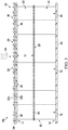
- FIGS. 4 and 5 illustrate one possible construction of the sandwich type linear acoustic facesheet 30 according to the embodiment shown in FIG. 3 .
- One or more linear material layers 34 are sandwiched between two outer facesheet layers 32a, 32b.
- each of the outer facesheet layers 32a, 32b comprises a composite material such as a thermoset or thermoplastic resin reinforced with unidirectional fibers.
- the composite material may take the form of a prepreg tape or slit prepreg tape, sometimes referred to as "tows".
- Outer facesheet layer 32a comprises a plurality of composite tape strips 38 having a 0° fiber orientation.
- the tape strips 38 have a desired width "W” and are spaced apart from each other to form gaps "G” therebetween.
- outer facesheet layer 32b comprises a plurality of composite tape strips 40 having a 90° fiber orientation, which also have a desired width "W” and are spaced apart to form gaps "G”.
- the values for "W” and “G” are chosen to give as high an open area as can be tolerated from a strength standpoint so the outer facesheet layer 32a will have a relatively small acoustic effect.
- tape strips 38, 40 extend orthogonal to each other and the gaps "G” form a hole pattern 42 of perforations 36 of the desired area.
- the area of each of the perforations 36 is determined by the size of the gaps "G" , and thus of the distance between the tape strips 38, 40.
- the tape strips 38, 40 may be laid down and placed using known automated fiber placement equipment (not shown).
- the linear acoustic facesheet 30 shown in FIGS. 4 and 5 may be laid up and the cured using autoclave or out of autoclave processing.
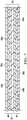
- FIGS. 6 and 7 illustrate another embodiment of a linear acoustic facesheet 30 formed by composite tape strips, and one or more layers of a linear material.
- one or more linear material layers 34 of the type previously described are sandwiched between multiple, acoustically transparent, laminated plies of composite material, each comprising unidirectional prepreg tape strips of a desired fiber orientation. More particularly, the linear material layer 34 is sandwiched between two laminated groups 45, 47 of plies, wherein which each ply group 45, 47 comprises a combination of composite tape strips formed of fiber reinforced thermoplastic or thermoset resin.
- the laminated ply group 45 comprises spaced composite tape strips 38a, 46a, 48a respectively having 0°, -60° and +60° fiber orientations.
- ply group 47 comprises spaced apart composite tape strips 38b, 46b and 48b respectively having 0°, -60°, and +60° fiber orientations.
- Other fiber orientations are possible, and each ply group 45, 47 may have more or less than three plies.
- the tape strips in the ply groups 45, 47 are arranged and aligned to form perforations 36 of a desired size and shape that collectively yield a desired open area.
- the total open area formed of by the perforations 36 may be between 40 and 50%.
- a similar construction employing composite tape strips of varying fiber orientations to form one or more outer facesheet layers 32 may be employed in the acoustic panel 10 shown in FIG. 1 and the acoustic panel 10a shown in FIG. 2 .
- the disclosed embodiments provide a simple, low-cost and effective method of fabricating an acoustic panel 10 for attenuating acoustic waves 44.
- the method broadly comprises, as previously discussed, producing a linear acoustic facesheet 30, septumizing a cellular core 12, and sandwiching the septumized cellular core 12 between the linear acoustic facesheet 30 and an imperforate backsheet 26.
- Producing the linear acoustic facesheet 30 includes producing an acoustically transparent outer facesheet layer 32, and attaching a layer 34 of the linear material to an acoustically transparent outer facesheet layer 32.
- the layer 34 linear material impedes the acoustic waves linearly over a range of acoustic wave frequencies.
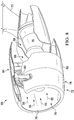
- FIG. 8 is a schematic view of an exemplary aircraft engine 60 that may include acoustic panels 10.
- Engine 60 includes a nacelle 62 that generally includes a fan section 64, a compressor section 66, a combustion section 68, and a turbine section 70.
- Engine 60 is typically attached to the wings, fuselage, or tail of an aircraft through appropriate mountings, for example, a pylon 71.
- Nacelle 62 includes a forward extension 72 having an outer wall 74 and an inner wall or air inlet lining 76.
- acoustic panels 10 are arranged to form at least a portion of inner wall 76 such that linear acoustic facesheet defines an air intake duct 78 for combustion section 68.
- Acoustic panel 10 facilitates reducing noise created by the high speed flow of air passing through intake duct 78 and into combustion section 68, as well as to reduce noise generated by a plurality of fan blades 80 of fan section 64.
- the acoustic panel 10 may be used on any surface portion of engine 60 in order to facilitate noise reduction. Further, it will be appreciated that the acoustic panel 10 may be used for reducing noise in various other engines or applications.
Claims (9)
- Panneau acoustique pour l'atténuation d'ondes acoustiques pour une entrée d'air moteur d'aéronef, comprenant :- une partie centrale (12) ayant des premier et second côtés (14, 16) et une pluralité d'alvéoles (18) s'étendant entre les premier et second côtés (14, 16) ;- une feuille arrière imperméable à l'air (26) sur le premier côté (14) de la partie centrale (12) ; et- une feuille avant acoustique linéaire (30) sur le second côté (16) de la partie centrale (12), incluant une couche de matériau linéaire (34) qui agit comme une couche d'impédance pour réduire l'amplitude des ondes acoustiques entrant dans la pluralité d'alvéoles (18), sensiblement au même degré, sur une plage de fréquences d'ondes acoustiques et de niveaux de pression ;- dans lequel la feuille avant acoustique linéaire (30) inclut une couche de feuille avant externe (32) qui est sensiblement transparente aux ondes acoustiques, dans lequel la couche de feuille avant externe (32) inclut des perforations à l'intérieur de celle-ci formant une zone ouverte dans la couche de feuille avant externe (32) entre approximativement 40 % à 50 % et dans lequel la couche de feuille avant externe (32) comprend une pluralité d'épaisseurs stratifiées de matériau composite, chacune des épaisseurs comprenant des bandes espacées de ruban de préimprégné unidirectionnel d'une orientation de fibres souhaitée ;- dans lequel la couche de matériau linéaire (34) est prise en sandwich entre la pluralité d'épaisseurs stratifiées.
- Panneau acoustique selon la revendication 1, comprenant en outre :un septum (20) à l'intérieur de la partie centrale (12) entre lesdits premier et second côtés (14, 16) de la partie centrale (12) ;dans lequel la couche de matériau linéaire (34) est un tissu tissé.
- Panneau acoustique selon les revendications 1 ou 2, dans lequel les couches de matériau linéaire sont tissées dans la couche de feuille avant externe (32).
- Panneau acoustique selon l'une quelconque des revendications 1 à 3, dans lequel la couche de matériau linéaire (34) est prise en sandwich entre la couche de feuille avant externe et le second côté de la partie centrale (12).
- Panneau acoustique selon l'une quelconque des revendications 1 à 4, dans lequel la couche de feuille avant externe (32) est prise en sandwich entre la couche de matériau linéaire (34) et le second côté de la partie centrale (12).
- Panneau acoustique selon l'une quelconque des revendications 1 à 5, dans lequel la couche de feuille avant externe (32) comprend une pluralité de bandes espacées de résine renforcée par des fibres unidirectionnelles ayant des orientations de fibres différentes.
- Panneau acoustique selon l'une quelconque des revendications 1 à 6, dans lequel les épaisseurs ont des orientations de fibres différentes et sont agencées pour former des perforations s'étendant à travers la couche de feuille avant externe.
- Procédé de fabrication d'un panneau acoustique pour atténuer des ondes acoustiques pour une entrée d'air moteur d'aéronef, comprenant :
la production d'une feuille avant acoustique linéaire (30), incluant la production d'une couche de feuille avant externe acoustiquement transparente (32) et la fixation d'une couche de matériau linéaire (34) à la couche de feuille avant externe acoustiquement transparente (32), dans lequel la couche de matériau linéaire (34) agit comme une couche d'impédance pour réduire l'amplitude des ondes acoustiques entrant dans la pluralité d'alvéoles (18), sensiblement au même degré, sur une plage de fréquences d'ondes acoustiques et de niveaux de pression, dans lequel la production de la couche de feuille avant externe acoustiquement transparente (32) inclut :le dépôt d'une pluralité d'épaisseurs de matériau composite, incluant la pose de bandes de ruban de préimprégné unidirectionnel ayant des orientations de fibres souhaitées et l'espacement des bandes de ruban de résine renforcée par des fibres les unes des autres ; etla prise en sandwich de la couche de matériau linéaire (34) entre la pluralité d'épaisseurs ;la fourniture d'une partie centrale alvéolaire (12) ; etla prise en sandwich de la partie centrale alvéolaire (12) entre la feuille avant acoustique linéaire (30) et une feuille arrière imperforée (26),dans lequel la couche de feuille avant externe (32) inclut des perforations à l'intérieur de celle-ci formant une zone ouverte dans la couche de feuille avant externe (32) entre approximativement 40 % à 50 %. - Procédé selon la revendication 8, comprenant en outre : la formation d'un septum dans la partie centrale alvéolaire (12).
Applications Claiming Priority (1)
| Application Number | Priority Date | Filing Date | Title |
|---|---|---|---|
| US13/953,287 US8820477B1 (en) | 2013-07-29 | 2013-07-29 | Acoustic panel |
Publications (3)
| Publication Number | Publication Date |
|---|---|
| EP2833356A2 EP2833356A2 (fr) | 2015-02-04 |
| EP2833356A3 EP2833356A3 (fr) | 2015-07-15 |
| EP2833356B1 true EP2833356B1 (fr) | 2019-12-11 |
Family
ID=51302628
Family Applications (1)
| Application Number | Title | Priority Date | Filing Date |
|---|---|---|---|
| EP14178888.5A Active EP2833356B1 (fr) | 2013-07-29 | 2014-07-29 | Panneau acoustique |
Country Status (3)
| Country | Link |
|---|---|
| US (1) | US8820477B1 (fr) |
| EP (1) | EP2833356B1 (fr) |
| CA (1) | CA2852436C (fr) |
Families Citing this family (43)
| Publication number | Priority date | Publication date | Assignee | Title |
|---|---|---|---|---|
| US9643392B2 (en) | 2013-07-29 | 2017-05-09 | The Boeing Company | Septumization of honeycomb sandwiches |
| US9592918B2 (en) * | 2014-06-23 | 2017-03-14 | Rohr, Inc. | Acoustic liner |
| US9693166B2 (en) | 2014-06-24 | 2017-06-27 | The Boeing Company | Automated production of acoustic structures |
| KR102355136B1 (ko) * | 2014-06-25 | 2022-01-26 | 엘지전자 주식회사 | 리니어 압축기, 리니어 압축기의 쉘, 리니어 압축기의 쉘 제작방법 |
| US9447576B2 (en) * | 2015-01-09 | 2016-09-20 | Rohr, Inc. | Post bond perforation of a septum in an acoustic panel |
| US9640164B2 (en) | 2015-02-27 | 2017-05-02 | The Boeing Company | Sound attenuation using a cellular core |
| US9587563B2 (en) | 2015-07-21 | 2017-03-07 | The Boeing Company | Sound attenuation apparatus and method |
| US9771868B2 (en) * | 2015-07-21 | 2017-09-26 | The Boeing Company | Sound attenuation apparatus and method |
| DE102015214709A1 (de) * | 2015-07-31 | 2017-02-02 | Mahle International Gmbh | Strömungskanal und Belüftungs-, Heizungs- oder Klimaanlage |
| US9764818B2 (en) | 2016-02-10 | 2017-09-19 | Rohr, Inc. | Structural, cellular core with corrugated support walls |
| US9761216B2 (en) | 2016-02-10 | 2017-09-12 | Rohr, Inc. | Acoustic panel with angled corrugated core structures |
| FR3049651B1 (fr) * | 2016-04-04 | 2019-06-21 | Airbus Operations | Panneau acoustique pour nacelle d'aeronef et procede de fabrication du panneau acoustique. |
| US9732677B1 (en) * | 2016-05-12 | 2017-08-15 | Rohr, Inc. | Broadband acoustic panels coupled with large secondary cavities to attenuate low frequencies |
| US10443496B2 (en) * | 2016-07-18 | 2019-10-15 | The Boeing Company | Acoustic paneling |
| US10720135B2 (en) | 2016-07-18 | 2020-07-21 | The Boeing Company | Acoustic panels that include multi-layer facesheets |
| FR3061347A1 (fr) * | 2016-12-23 | 2018-06-29 | Airbus Operations | Procede d'obtention d'une couche acoustique poreuse et couche acoustique poreuse ainsi obtenue |
| US10414481B2 (en) | 2017-02-14 | 2019-09-17 | Rohr, Inc. | Method for forming a structural panel |
| NL2018888B1 (en) * | 2017-05-10 | 2018-11-15 | Boeing Co | Acoustic paneling |
| US10525636B2 (en) | 2017-06-19 | 2020-01-07 | Rohr, Inc. | Process for forming a fiber-reinforced composite structure |
| US10695986B2 (en) | 2017-08-22 | 2020-06-30 | Rohr, Inc. | Method for forming a structural panel |
| US11125157B2 (en) | 2017-09-22 | 2021-09-21 | The Boeing Company | Advanced inlet design |
| FR3072365B1 (fr) * | 2017-10-12 | 2020-11-13 | Safran Aircraft Engines | Attenuation acoustique sur une paroi de turbomachine |
| US11060480B2 (en) * | 2017-11-14 | 2021-07-13 | The Boeing Company | Sound-attenuating heat exchangers and methods of utilizing the same |
| US11092077B2 (en) * | 2018-03-28 | 2021-08-17 | Pratt & Whitney Canada Corp. | Aircraft component and method of manufacture |
| US10906659B2 (en) | 2018-04-03 | 2021-02-02 | Rohr, Inc. | Structured panel with structural reinforcement(s) |
| US11325718B2 (en) * | 2018-05-02 | 2022-05-10 | Rohr, Inc. | Aircraft propulsion system assembly including one or more acoustic panels |
| US11231234B2 (en) | 2018-10-26 | 2022-01-25 | Toyota Motor Engineering & Manufacturing North America, Inc. | Acoustic panel with vapor chambers |
| US11227573B2 (en) | 2018-10-26 | 2022-01-18 | Toyota Motor Engineering & Manufacturing North America, Inc. | Acoustic panel with acoustic unit layer |
| US11398214B2 (en) | 2018-12-14 | 2022-07-26 | Rohr, Inc. | Forming a structured panel with one or more structural reinforcements |
| US11242822B2 (en) | 2018-12-14 | 2022-02-08 | Rohr, Inc. | Structured panel with multi-panel structure(s) |
| US11260641B2 (en) | 2019-05-10 | 2022-03-01 | American Honda Motor Co., Inc. | Apparatus for reticulation of adhesive and methods of use thereof |
| US11572850B2 (en) | 2019-06-04 | 2023-02-07 | Rohr, Inc. | Acoustic panel with one or more structural stiffeners |
| US11168584B2 (en) | 2019-06-28 | 2021-11-09 | The Boeing Company | Thermal management system using shape memory alloy actuator |
| US11143170B2 (en) | 2019-06-28 | 2021-10-12 | The Boeing Company | Shape memory alloy lifting tubes and shape memory alloy actuators including the same |
| US11525438B2 (en) | 2019-06-28 | 2022-12-13 | The Boeing Company | Shape memory alloy actuators and thermal management systems including the same |
| DE102019118591B4 (de) | 2019-07-09 | 2022-02-10 | Deutsche Institute Für Textil- Und Faserforschung Denkendorf | Schallabsorberanordnung |
| FR3103054B1 (fr) * | 2019-11-07 | 2021-11-19 | Airbus Operations Sas | Panneau acoustique pour nacelle d’aéronef à absorption multifréquence. |
| US11662048B2 (en) | 2020-03-30 | 2023-05-30 | Toyota Motor Engineering & Manufacturing North America, Inc. | Compact duct sound absorber |
| US20210363748A1 (en) * | 2020-05-21 | 2021-11-25 | The Boeing Company | Sound absorbing panels |
| FR3116642A1 (fr) * | 2020-11-24 | 2022-05-27 | Airbus Operations | Coque de peau résistive intégrant des bandes métalliques perforées, et paroi interne acoustique d’une entrée d’air d’aéronef formée à partir de telles coques de peau résistive. |
| US20220366886A1 (en) * | 2021-05-12 | 2022-11-17 | B/E Aerospace, Inc | Aircraft acoustic panel |
| US11780179B2 (en) | 2021-09-02 | 2023-10-10 | Rohr, Inc. | Thermoplastic composite panel with corrugated peaks and troughs stiffening systems and methods |
| US20230064499A1 (en) * | 2021-09-02 | 2023-03-02 | Rohr, Inc. | Corrugated acoustic stiffening devices and methods |
Citations (3)
| Publication number | Priority date | Publication date | Assignee | Title |
|---|---|---|---|---|
| GB2122540A (en) * | 1982-05-19 | 1984-01-18 | Short Brothers Ltd | Means for attenuating sound energy, and method of manufacture thereof |
| GB2349445A (en) * | 1999-04-26 | 2000-11-01 | Short Brothers Plc | Noise attenuation panel |
| US20100148001A1 (en) * | 2008-12-17 | 2010-06-17 | Airbus Operations Gmbh | Aircraft cabin panel with core recesses for acoustic absorption |
Family Cites Families (29)
| Publication number | Priority date | Publication date | Assignee | Title |
|---|---|---|---|---|
| US3700067A (en) | 1970-06-01 | 1972-10-24 | Mc Donnell Douglas Corp | Acoustic face sheet |
| US3831710A (en) | 1973-01-24 | 1974-08-27 | Lockheed Aircraft Corp | Sound absorbing panel |
| US4257998A (en) | 1978-05-01 | 1981-03-24 | The Boenig Company | Method of making a cellular core with internal septum |
| US4265955A (en) * | 1978-05-01 | 1981-05-05 | The Boeing Company | Honeycomb core with internal septum and method of making same |
| US4235303A (en) | 1978-11-20 | 1980-11-25 | The Boeing Company | Combination bulk absorber-honeycomb acoustic panels |
| GB2056367B (en) | 1979-07-06 | 1983-06-02 | Rohr Industries Inc | Process for producing noise attenuation panels |
| US4248647A (en) * | 1979-08-07 | 1981-02-03 | Armstrong Cork Company | Method for producing acoustical ceiling tile faced with a smooth distortion free decorative thin plastic film |
| US4384020A (en) | 1980-12-22 | 1983-05-17 | Rohr Industries, Inc. | Honeycomb noise attenuating structures |
| US4452335A (en) | 1982-05-03 | 1984-06-05 | United Technologies Corporation | Sound absorbing structure for a gas turbine engine |
| US4465725A (en) | 1982-07-15 | 1984-08-14 | Rohr Industries, Inc. | Noise suppression panel |
| US4671841A (en) * | 1986-01-06 | 1987-06-09 | Rohr Industries, Inc. | Method of making an acoustic panel with a triaxial open-weave face sheet |
| GB8817669D0 (en) | 1988-07-25 | 1988-09-01 | Short Brothers Ltd | Means for attenuating sound energy |
| US5041323A (en) | 1989-10-26 | 1991-08-20 | Rohr Industries, Inc. | Honeycomb noise attenuation structure |
| US5175401A (en) * | 1991-03-18 | 1992-12-29 | Grumman Aerospace Corporation | Segmented resistance acoustic attenuating liner |
| US5997985A (en) | 1998-09-10 | 1999-12-07 | Northrop Grumman Corporation | Method of forming acoustic attenuation chambers using laser processing of multi-layered polymer films |
| US6182787B1 (en) * | 1999-01-12 | 2001-02-06 | General Electric Company | Rigid sandwich panel acoustic treatment |
| FR2803077B1 (fr) * | 1999-12-24 | 2002-07-26 | Aerospatiale Matra Airbus | Procede de realisation d'une couche acoustiquement resistive, couche resistive obtenue et paroi utilisant une telle couche |
| US6509081B1 (en) | 2000-09-28 | 2003-01-21 | The Boeing Company | No-septum acoustic sandwich panel, and apparatus and method for suppressing noise in a nozzle |
| FR2838860B1 (fr) * | 2002-04-17 | 2005-01-21 | Airbus France | Couche acoustiquement resistive multicomposant pour panneau d'attenuation acoustique et panneau ainsi obtenu |
| US6767606B2 (en) | 2002-08-29 | 2004-07-27 | The Boeing Company | Vented cell structure and fabrication method |
| US7588212B2 (en) | 2003-07-08 | 2009-09-15 | Rohr Inc. | Method and apparatus for noise abatement and ice protection of an aircraft engine nacelle inlet lip |
| US7328771B2 (en) | 2004-07-27 | 2008-02-12 | United Technologies Corporation | Zero acoustic splice fan case liner |
| US8413761B2 (en) | 2005-04-04 | 2013-04-09 | Hexcel Corporation | Acoustic honeycomb with perforated septum caps |
| US7510052B2 (en) | 2005-04-04 | 2009-03-31 | Hexcel Corporation | Acoustic septum cap honeycomb |
| US7434659B2 (en) | 2005-04-04 | 2008-10-14 | Hexcel Corporation | Acoustic septum cap honeycomb |
| FR2912186B1 (fr) | 2007-02-01 | 2013-07-05 | Airbus France | Dispositif de traitement acoustique des bruits de turbine et de combustion |
| JP2009062977A (ja) * | 2007-08-15 | 2009-03-26 | Rohr Inc | 線形音響ライナー |
| US7913813B1 (en) | 2009-10-21 | 2011-03-29 | The Boeing Company | Noise shield for a launch vehicle |
| US8511429B1 (en) * | 2012-02-13 | 2013-08-20 | Usg Interiors, Llc | Ceiling panels made from corrugated cardboard |
-
2013
- 2013-07-29 US US13/953,287 patent/US8820477B1/en active Active
-
2014
- 2014-05-26 CA CA2852436A patent/CA2852436C/fr active Active
- 2014-07-29 EP EP14178888.5A patent/EP2833356B1/fr active Active
Patent Citations (3)
| Publication number | Priority date | Publication date | Assignee | Title |
|---|---|---|---|---|
| GB2122540A (en) * | 1982-05-19 | 1984-01-18 | Short Brothers Ltd | Means for attenuating sound energy, and method of manufacture thereof |
| GB2349445A (en) * | 1999-04-26 | 2000-11-01 | Short Brothers Plc | Noise attenuation panel |
| US20100148001A1 (en) * | 2008-12-17 | 2010-06-17 | Airbus Operations Gmbh | Aircraft cabin panel with core recesses for acoustic absorption |
Also Published As
| Publication number | Publication date |
|---|---|
| US8820477B1 (en) | 2014-09-02 |
| CA2852436A1 (fr) | 2015-01-29 |
| EP2833356A3 (fr) | 2015-07-15 |
| CA2852436C (fr) | 2017-05-02 |
| EP2833356A2 (fr) | 2015-02-04 |
Similar Documents
| Publication | Publication Date | Title |
|---|---|---|
| EP2833356B1 (fr) | Panneau acoustique | |
| EP3033746B1 (fr) | Guide d'onde sonore destiné à être utilisé dans des structures acoustiques | |
| EP3295455B1 (fr) | Structures acoustiques avec plusieurs degrés de liberté | |
| US8646574B2 (en) | Acoustic skin for an aircraft nacelle acoustic panel | |
| EP2472509B1 (fr) | Cloison pour structure acoustique en nid d'abeilles | |
| EP3244038B1 (fr) | Panneaux acoustiques comprenant des grandes cavités secondaires pour atténuer les basses fréquences | |
| US6182787B1 (en) | Rigid sandwich panel acoustic treatment | |
| KR102228530B1 (ko) | 내부 격막을 갖춘 허니콤을 포함하는 소음 흡수 구조물 | |
| EP0509166B1 (fr) | Structure en nid d'abeilles pour l'atténuation du bruit | |
| EP2847755B1 (fr) | Structure acoustique à suppression de bande passante accrue | |
| US10961913B2 (en) | Acoustic liners for use in a turbine engine | |
| EP2953130B1 (fr) | Structures de panneaux sandwich d'atténuation acoustique | |
| CA2852438C (fr) | Nid-d'abeilles acoustique dote de capsules a septum perforees | |
| CA2638706C (fr) | Revetement insonorisant lineaire | |
| US6772857B2 (en) | Acoustically resistive layer for an acoustical attenuation panel, panel using such a layer | |
| US6607625B2 (en) | Process for the production of an acoustively resistive layer, resistive layer thus obtained, and wall using such layer | |
| US9620102B1 (en) | Stepped acoustic structures with multiple degrees of freedom | |
| US10577117B2 (en) | Angled acoustic honeycomb | |
| EP3678128B1 (fr) | Revêtement acoustique et procédé de formation d'un revêtement acoustique | |
| CN113490978A (zh) | 用于制造具有开口的内部圆锥形状的蜂窝芯体的方法 |
Legal Events
| Date | Code | Title | Description |
|---|---|---|---|
| 17P | Request for examination filed |
Effective date: 20140729 |
|
| AK | Designated contracting states |
Kind code of ref document: A2 Designated state(s): AL AT BE BG CH CY CZ DE DK EE ES FI FR GB GR HR HU IE IS IT LI LT LU LV MC MK MT NL NO PL PT RO RS SE SI SK SM TR |
|
| AX | Request for extension of the european patent |
Extension state: BA ME |
|
| PUAI | Public reference made under article 153(3) epc to a published international application that has entered the european phase |
Free format text: ORIGINAL CODE: 0009012 |
|
| PUAL | Search report despatched |
Free format text: ORIGINAL CODE: 0009013 |
|
| AK | Designated contracting states |
Kind code of ref document: A3 Designated state(s): AL AT BE BG CH CY CZ DE DK EE ES FI FR GB GR HR HU IE IS IT LI LT LU LV MC MK MT NL NO PL PT RO RS SE SI SK SM TR |
|
| AX | Request for extension of the european patent |
Extension state: BA ME |
|
| RIC1 | Information provided on ipc code assigned before grant |
Ipc: F02K 1/82 20060101ALI20150608BHEP Ipc: G10K 11/168 20060101AFI20150608BHEP |
|
| 17Q | First examination report despatched |
Effective date: 20161007 |
|
| STAA | Information on the status of an ep patent application or granted ep patent |
Free format text: STATUS: EXAMINATION IS IN PROGRESS |
|
| REG | Reference to a national code |
Ref country code: DE Ref legal event code: R079 Ref document number: 602014058149 Country of ref document: DE Free format text: PREVIOUS MAIN CLASS: G10K0011168000 Ipc: G10K0011172000 |
|
| GRAP | Despatch of communication of intention to grant a patent |
Free format text: ORIGINAL CODE: EPIDOSNIGR1 |
|
| STAA | Information on the status of an ep patent application or granted ep patent |
Free format text: STATUS: GRANT OF PATENT IS INTENDED |
|
| RIC1 | Information provided on ipc code assigned before grant |
Ipc: G10K 11/168 20060101ALI20181204BHEP Ipc: G10K 11/172 20060101AFI20181204BHEP |
|
| INTG | Intention to grant announced |
Effective date: 20190107 |
|
| GRAJ | Information related to disapproval of communication of intention to grant by the applicant or resumption of examination proceedings by the epo deleted |
Free format text: ORIGINAL CODE: EPIDOSDIGR1 |
|
| STAA | Information on the status of an ep patent application or granted ep patent |
Free format text: STATUS: EXAMINATION IS IN PROGRESS |
|
| GRAP | Despatch of communication of intention to grant a patent |
Free format text: ORIGINAL CODE: EPIDOSNIGR1 |
|
| STAA | Information on the status of an ep patent application or granted ep patent |
Free format text: STATUS: GRANT OF PATENT IS INTENDED |
|
| INTG | Intention to grant announced |
Effective date: 20190603 |
|
| GRAS | Grant fee paid |
Free format text: ORIGINAL CODE: EPIDOSNIGR3 |
|
| GRAJ | Information related to disapproval of communication of intention to grant by the applicant or resumption of examination proceedings by the epo deleted |
Free format text: ORIGINAL CODE: EPIDOSDIGR1 |
|
| GRAL | Information related to payment of fee for publishing/printing deleted |
Free format text: ORIGINAL CODE: EPIDOSDIGR3 |
|
| STAA | Information on the status of an ep patent application or granted ep patent |
Free format text: STATUS: EXAMINATION IS IN PROGRESS |
|
| GRAR | Information related to intention to grant a patent recorded |
Free format text: ORIGINAL CODE: EPIDOSNIGR71 |
|
| STAA | Information on the status of an ep patent application or granted ep patent |
Free format text: STATUS: GRANT OF PATENT IS INTENDED |
|
| INTC | Intention to grant announced (deleted) | ||
| GRAA | (expected) grant |
Free format text: ORIGINAL CODE: 0009210 |
|
| STAA | Information on the status of an ep patent application or granted ep patent |
Free format text: STATUS: THE PATENT HAS BEEN GRANTED |
|
| INTG | Intention to grant announced |
Effective date: 20191030 |
|
| AK | Designated contracting states |
Kind code of ref document: B1 Designated state(s): AL AT BE BG CH CY CZ DE DK EE ES FI FR GB GR HR HU IE IS IT LI LT LU LV MC MK MT NL NO PL PT RO RS SE SI SK SM TR |
|
| REG | Reference to a national code |
Ref country code: GB Ref legal event code: FG4D |
|
| REG | Reference to a national code |
Ref country code: CH Ref legal event code: EP |
|
| REG | Reference to a national code |
Ref country code: AT Ref legal event code: REF Ref document number: 1212983 Country of ref document: AT Kind code of ref document: T Effective date: 20191215 |
|
| REG | Reference to a national code |
Ref country code: DE Ref legal event code: R096 Ref document number: 602014058149 Country of ref document: DE |
|
| REG | Reference to a national code |
Ref country code: IE Ref legal event code: FG4D |
|
| REG | Reference to a national code |
Ref country code: NL Ref legal event code: MP Effective date: 20191211 |
|
| REG | Reference to a national code |
Ref country code: LT Ref legal event code: MG4D |
|
| PG25 | Lapsed in a contracting state [announced via postgrant information from national office to epo] |
Ref country code: NO Free format text: LAPSE BECAUSE OF FAILURE TO SUBMIT A TRANSLATION OF THE DESCRIPTION OR TO PAY THE FEE WITHIN THE PRESCRIBED TIME-LIMIT Effective date: 20200311 Ref country code: GR Free format text: LAPSE BECAUSE OF FAILURE TO SUBMIT A TRANSLATION OF THE DESCRIPTION OR TO PAY THE FEE WITHIN THE PRESCRIBED TIME-LIMIT Effective date: 20200312 Ref country code: LT Free format text: LAPSE BECAUSE OF FAILURE TO SUBMIT A TRANSLATION OF THE DESCRIPTION OR TO PAY THE FEE WITHIN THE PRESCRIBED TIME-LIMIT Effective date: 20191211 Ref country code: ES Free format text: LAPSE BECAUSE OF FAILURE TO SUBMIT A TRANSLATION OF THE DESCRIPTION OR TO PAY THE FEE WITHIN THE PRESCRIBED TIME-LIMIT Effective date: 20191211 Ref country code: SE Free format text: LAPSE BECAUSE OF FAILURE TO SUBMIT A TRANSLATION OF THE DESCRIPTION OR TO PAY THE FEE WITHIN THE PRESCRIBED TIME-LIMIT Effective date: 20191211 Ref country code: LV Free format text: LAPSE BECAUSE OF FAILURE TO SUBMIT A TRANSLATION OF THE DESCRIPTION OR TO PAY THE FEE WITHIN THE PRESCRIBED TIME-LIMIT Effective date: 20191211 Ref country code: FI Free format text: LAPSE BECAUSE OF FAILURE TO SUBMIT A TRANSLATION OF THE DESCRIPTION OR TO PAY THE FEE WITHIN THE PRESCRIBED TIME-LIMIT Effective date: 20191211 Ref country code: BG Free format text: LAPSE BECAUSE OF FAILURE TO SUBMIT A TRANSLATION OF THE DESCRIPTION OR TO PAY THE FEE WITHIN THE PRESCRIBED TIME-LIMIT Effective date: 20200311 |
|
| PG25 | Lapsed in a contracting state [announced via postgrant information from national office to epo] |
Ref country code: RS Free format text: LAPSE BECAUSE OF FAILURE TO SUBMIT A TRANSLATION OF THE DESCRIPTION OR TO PAY THE FEE WITHIN THE PRESCRIBED TIME-LIMIT Effective date: 20191211 Ref country code: HR Free format text: LAPSE BECAUSE OF FAILURE TO SUBMIT A TRANSLATION OF THE DESCRIPTION OR TO PAY THE FEE WITHIN THE PRESCRIBED TIME-LIMIT Effective date: 20191211 |
|
| PG25 | Lapsed in a contracting state [announced via postgrant information from national office to epo] |
Ref country code: AL Free format text: LAPSE BECAUSE OF FAILURE TO SUBMIT A TRANSLATION OF THE DESCRIPTION OR TO PAY THE FEE WITHIN THE PRESCRIBED TIME-LIMIT Effective date: 20191211 |
|
| PG25 | Lapsed in a contracting state [announced via postgrant information from national office to epo] |
Ref country code: PT Free format text: LAPSE BECAUSE OF FAILURE TO SUBMIT A TRANSLATION OF THE DESCRIPTION OR TO PAY THE FEE WITHIN THE PRESCRIBED TIME-LIMIT Effective date: 20200506 Ref country code: EE Free format text: LAPSE BECAUSE OF FAILURE TO SUBMIT A TRANSLATION OF THE DESCRIPTION OR TO PAY THE FEE WITHIN THE PRESCRIBED TIME-LIMIT Effective date: 20191211 Ref country code: CZ Free format text: LAPSE BECAUSE OF FAILURE TO SUBMIT A TRANSLATION OF THE DESCRIPTION OR TO PAY THE FEE WITHIN THE PRESCRIBED TIME-LIMIT Effective date: 20191211 Ref country code: NL Free format text: LAPSE BECAUSE OF FAILURE TO SUBMIT A TRANSLATION OF THE DESCRIPTION OR TO PAY THE FEE WITHIN THE PRESCRIBED TIME-LIMIT Effective date: 20191211 Ref country code: RO Free format text: LAPSE BECAUSE OF FAILURE TO SUBMIT A TRANSLATION OF THE DESCRIPTION OR TO PAY THE FEE WITHIN THE PRESCRIBED TIME-LIMIT Effective date: 20191211 |
|
| PG25 | Lapsed in a contracting state [announced via postgrant information from national office to epo] |
Ref country code: SK Free format text: LAPSE BECAUSE OF FAILURE TO SUBMIT A TRANSLATION OF THE DESCRIPTION OR TO PAY THE FEE WITHIN THE PRESCRIBED TIME-LIMIT Effective date: 20191211 Ref country code: IS Free format text: LAPSE BECAUSE OF FAILURE TO SUBMIT A TRANSLATION OF THE DESCRIPTION OR TO PAY THE FEE WITHIN THE PRESCRIBED TIME-LIMIT Effective date: 20200411 Ref country code: SM Free format text: LAPSE BECAUSE OF FAILURE TO SUBMIT A TRANSLATION OF THE DESCRIPTION OR TO PAY THE FEE WITHIN THE PRESCRIBED TIME-LIMIT Effective date: 20191211 |
|
| REG | Reference to a national code |
Ref country code: DE Ref legal event code: R097 Ref document number: 602014058149 Country of ref document: DE |
|
| REG | Reference to a national code |
Ref country code: AT Ref legal event code: MK05 Ref document number: 1212983 Country of ref document: AT Kind code of ref document: T Effective date: 20191211 |
|
| PLBE | No opposition filed within time limit |
Free format text: ORIGINAL CODE: 0009261 |
|
| STAA | Information on the status of an ep patent application or granted ep patent |
Free format text: STATUS: NO OPPOSITION FILED WITHIN TIME LIMIT |
|
| PG25 | Lapsed in a contracting state [announced via postgrant information from national office to epo] |
Ref country code: DK Free format text: LAPSE BECAUSE OF FAILURE TO SUBMIT A TRANSLATION OF THE DESCRIPTION OR TO PAY THE FEE WITHIN THE PRESCRIBED TIME-LIMIT Effective date: 20191211 |
|
| 26N | No opposition filed |
Effective date: 20200914 |
|
| PG25 | Lapsed in a contracting state [announced via postgrant information from national office to epo] |
Ref country code: PL Free format text: LAPSE BECAUSE OF FAILURE TO SUBMIT A TRANSLATION OF THE DESCRIPTION OR TO PAY THE FEE WITHIN THE PRESCRIBED TIME-LIMIT Effective date: 20191211 Ref country code: SI Free format text: LAPSE BECAUSE OF FAILURE TO SUBMIT A TRANSLATION OF THE DESCRIPTION OR TO PAY THE FEE WITHIN THE PRESCRIBED TIME-LIMIT Effective date: 20191211 Ref country code: AT Free format text: LAPSE BECAUSE OF FAILURE TO SUBMIT A TRANSLATION OF THE DESCRIPTION OR TO PAY THE FEE WITHIN THE PRESCRIBED TIME-LIMIT Effective date: 20191211 |
|
| PG25 | Lapsed in a contracting state [announced via postgrant information from national office to epo] |
Ref country code: IT Free format text: LAPSE BECAUSE OF FAILURE TO SUBMIT A TRANSLATION OF THE DESCRIPTION OR TO PAY THE FEE WITHIN THE PRESCRIBED TIME-LIMIT Effective date: 20191211 |
|
| PG25 | Lapsed in a contracting state [announced via postgrant information from national office to epo] |
Ref country code: MC Free format text: LAPSE BECAUSE OF FAILURE TO SUBMIT A TRANSLATION OF THE DESCRIPTION OR TO PAY THE FEE WITHIN THE PRESCRIBED TIME-LIMIT Effective date: 20191211 |
|
| REG | Reference to a national code |
Ref country code: CH Ref legal event code: PL |
|
| REG | Reference to a national code |
Ref country code: BE Ref legal event code: MM Effective date: 20200731 |
|
| PG25 | Lapsed in a contracting state [announced via postgrant information from national office to epo] |
Ref country code: LI Free format text: LAPSE BECAUSE OF NON-PAYMENT OF DUE FEES Effective date: 20200731 Ref country code: CH Free format text: LAPSE BECAUSE OF NON-PAYMENT OF DUE FEES Effective date: 20200731 Ref country code: LU Free format text: LAPSE BECAUSE OF NON-PAYMENT OF DUE FEES Effective date: 20200729 |
|
| PG25 | Lapsed in a contracting state [announced via postgrant information from national office to epo] |
Ref country code: BE Free format text: LAPSE BECAUSE OF NON-PAYMENT OF DUE FEES Effective date: 20200731 |
|
| PG25 | Lapsed in a contracting state [announced via postgrant information from national office to epo] |
Ref country code: IE Free format text: LAPSE BECAUSE OF NON-PAYMENT OF DUE FEES Effective date: 20200729 |
|
| PG25 | Lapsed in a contracting state [announced via postgrant information from national office to epo] |
Ref country code: TR Free format text: LAPSE BECAUSE OF FAILURE TO SUBMIT A TRANSLATION OF THE DESCRIPTION OR TO PAY THE FEE WITHIN THE PRESCRIBED TIME-LIMIT Effective date: 20191211 Ref country code: MT Free format text: LAPSE BECAUSE OF FAILURE TO SUBMIT A TRANSLATION OF THE DESCRIPTION OR TO PAY THE FEE WITHIN THE PRESCRIBED TIME-LIMIT Effective date: 20191211 Ref country code: CY Free format text: LAPSE BECAUSE OF FAILURE TO SUBMIT A TRANSLATION OF THE DESCRIPTION OR TO PAY THE FEE WITHIN THE PRESCRIBED TIME-LIMIT Effective date: 20191211 |
|
| PG25 | Lapsed in a contracting state [announced via postgrant information from national office to epo] |
Ref country code: MK Free format text: LAPSE BECAUSE OF FAILURE TO SUBMIT A TRANSLATION OF THE DESCRIPTION OR TO PAY THE FEE WITHIN THE PRESCRIBED TIME-LIMIT Effective date: 20191211 |
|
| P01 | Opt-out of the competence of the unified patent court (upc) registered |
Effective date: 20230516 |
|
| PGFP | Annual fee paid to national office [announced via postgrant information from national office to epo] |
Ref country code: GB Payment date: 20230727 Year of fee payment: 10 |
|
| PGFP | Annual fee paid to national office [announced via postgrant information from national office to epo] |
Ref country code: FR Payment date: 20230725 Year of fee payment: 10 Ref country code: DE Payment date: 20230727 Year of fee payment: 10 |