EP2833234A1 - Curved display device and method of controlling curvature thereof - Google Patents
Curved display device and method of controlling curvature thereof Download PDFInfo
- Publication number
- EP2833234A1 EP2833234A1 EP20130196027 EP13196027A EP2833234A1 EP 2833234 A1 EP2833234 A1 EP 2833234A1 EP 20130196027 EP20130196027 EP 20130196027 EP 13196027 A EP13196027 A EP 13196027A EP 2833234 A1 EP2833234 A1 EP 2833234A1
- Authority
- EP
- European Patent Office
- Prior art keywords
- bottom cover
- pair
- support pieces
- main body
- turnbuckle
- Prior art date
- Legal status (The legal status is an assumption and is not a legal conclusion. Google has not performed a legal analysis and makes no representation as to the accuracy of the status listed.)
- Granted
Links
Images







Classifications
-
- G—PHYSICS
- G09—EDUCATION; CRYPTOGRAPHY; DISPLAY; ADVERTISING; SEALS
- G09F—DISPLAYING; ADVERTISING; SIGNS; LABELS OR NAME-PLATES; SEALS
- G09F9/00—Indicating arrangements for variable information in which the information is built-up on a support by selection or combination of individual elements
-
- G—PHYSICS
- G09—EDUCATION; CRYPTOGRAPHY; DISPLAY; ADVERTISING; SEALS
- G09F—DISPLAYING; ADVERTISING; SIGNS; LABELS OR NAME-PLATES; SEALS
- G09F9/00—Indicating arrangements for variable information in which the information is built-up on a support by selection or combination of individual elements
- G09F9/30—Indicating arrangements for variable information in which the information is built-up on a support by selection or combination of individual elements in which the desired character or characters are formed by combining individual elements
- G09F9/301—Indicating arrangements for variable information in which the information is built-up on a support by selection or combination of individual elements in which the desired character or characters are formed by combining individual elements flexible foldable or roll-able electronic displays, e.g. thin LCD, OLED
-
- G—PHYSICS
- G09—EDUCATION; CRYPTOGRAPHY; DISPLAY; ADVERTISING; SEALS
- G09G—ARRANGEMENTS OR CIRCUITS FOR CONTROL OF INDICATING DEVICES USING STATIC MEANS TO PRESENT VARIABLE INFORMATION
- G09G5/00—Control arrangements or circuits for visual indicators common to cathode-ray tube indicators and other visual indicators
-
- G—PHYSICS
- G02—OPTICS
- G02F—OPTICAL DEVICES OR ARRANGEMENTS FOR THE CONTROL OF LIGHT BY MODIFICATION OF THE OPTICAL PROPERTIES OF THE MEDIA OF THE ELEMENTS INVOLVED THEREIN; NON-LINEAR OPTICS; FREQUENCY-CHANGING OF LIGHT; OPTICAL LOGIC ELEMENTS; OPTICAL ANALOGUE/DIGITAL CONVERTERS
- G02F1/00—Devices or arrangements for the control of the intensity, colour, phase, polarisation or direction of light arriving from an independent light source, e.g. switching, gating or modulating; Non-linear optics
- G02F1/01—Devices or arrangements for the control of the intensity, colour, phase, polarisation or direction of light arriving from an independent light source, e.g. switching, gating or modulating; Non-linear optics for the control of the intensity, phase, polarisation or colour
- G02F1/13—Devices or arrangements for the control of the intensity, colour, phase, polarisation or direction of light arriving from an independent light source, e.g. switching, gating or modulating; Non-linear optics for the control of the intensity, phase, polarisation or colour based on liquid crystals, e.g. single liquid crystal display cells
- G02F1/133—Constructional arrangements; Operation of liquid crystal cells; Circuit arrangements
- G02F1/1333—Constructional arrangements; Manufacturing methods
- G02F1/133308—Support structures for LCD panels, e.g. frames or bezels
-
- G—PHYSICS
- G06—COMPUTING OR CALCULATING; COUNTING
- G06F—ELECTRIC DIGITAL DATA PROCESSING
- G06F1/00—Details not covered by groups G06F3/00 - G06F13/00 and G06F21/00
- G06F1/16—Constructional details or arrangements
- G06F1/1601—Constructional details related to the housing of computer displays, e.g. of CRT monitors, of flat displays
-
- G—PHYSICS
- G09—EDUCATION; CRYPTOGRAPHY; DISPLAY; ADVERTISING; SEALS
- G09G—ARRANGEMENTS OR CIRCUITS FOR CONTROL OF INDICATING DEVICES USING STATIC MEANS TO PRESENT VARIABLE INFORMATION
- G09G3/00—Control arrangements or circuits, of interest only in connection with visual indicators other than cathode-ray tubes
- G09G3/20—Control arrangements or circuits, of interest only in connection with visual indicators other than cathode-ray tubes for presentation of an assembly of a number of characters, e.g. a page, by composing the assembly by combination of individual elements arranged in a matrix no fixed position being assigned to or needed to be assigned to the individual characters or partial characters
- G09G3/34—Control arrangements or circuits, of interest only in connection with visual indicators other than cathode-ray tubes for presentation of an assembly of a number of characters, e.g. a page, by composing the assembly by combination of individual elements arranged in a matrix no fixed position being assigned to or needed to be assigned to the individual characters or partial characters by control of light from an independent source
- G09G3/36—Control arrangements or circuits, of interest only in connection with visual indicators other than cathode-ray tubes for presentation of an assembly of a number of characters, e.g. a page, by composing the assembly by combination of individual elements arranged in a matrix no fixed position being assigned to or needed to be assigned to the individual characters or partial characters by control of light from an independent source using liquid crystals
- G09G3/3611—Control of matrices with row and column drivers
- G09G3/3685—Details of drivers for data electrodes
- G09G3/3688—Details of drivers for data electrodes suitable for active matrices only
-
- G—PHYSICS
- G02—OPTICS
- G02F—OPTICAL DEVICES OR ARRANGEMENTS FOR THE CONTROL OF LIGHT BY MODIFICATION OF THE OPTICAL PROPERTIES OF THE MEDIA OF THE ELEMENTS INVOLVED THEREIN; NON-LINEAR OPTICS; FREQUENCY-CHANGING OF LIGHT; OPTICAL LOGIC ELEMENTS; OPTICAL ANALOGUE/DIGITAL CONVERTERS
- G02F1/00—Devices or arrangements for the control of the intensity, colour, phase, polarisation or direction of light arriving from an independent light source, e.g. switching, gating or modulating; Non-linear optics
- G02F1/01—Devices or arrangements for the control of the intensity, colour, phase, polarisation or direction of light arriving from an independent light source, e.g. switching, gating or modulating; Non-linear optics for the control of the intensity, phase, polarisation or colour
- G02F1/13—Devices or arrangements for the control of the intensity, colour, phase, polarisation or direction of light arriving from an independent light source, e.g. switching, gating or modulating; Non-linear optics for the control of the intensity, phase, polarisation or colour based on liquid crystals, e.g. single liquid crystal display cells
- G02F1/133—Constructional arrangements; Operation of liquid crystal cells; Circuit arrangements
- G02F1/1333—Constructional arrangements; Manufacturing methods
- G02F1/133308—Support structures for LCD panels, e.g. frames or bezels
- G02F1/133314—Back frames
Definitions
- the present invention relates to a curved display device and a method of controlling curvature thereof.
- Such flat panel display devices include Liquid Crystal Display (LCD) devices and Organic Light Emitting Diode (OLED) display devices, for example. Most of such flat panel display devices are used in TVs, laptop computers, MP3 players, cellular phones, and the like.
- LCD Liquid Crystal Display
- OLED Organic Light Emitting Diode
- flat panel display devices typically include a planar screen.
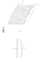
- flat panel display devices having a curved screen may be more suitable for users according to use purposes. Accordingly, as exemplarily shown in FIG. 1 , a method of manufacturing a curved display device by coupling a display panel 2 to a casing member 4 having a specific curvature has been introduced in the related art.
- the curved display device of the related art makes it difficult for a user to vary curvature of the display panel according to desired situations because of mass production of the casing member 4 having a fixed curvature.
- the present invention is directed to a curved display device and a method of controlling curvature thereof that substantially obviate one or more problems due to limitations and disadvantages of the related art.
- An object of the present invention is to provide a curved display device and a method of controlling curvature thereof, which enable variation in the curvature of a display panel.
- a curved display device includes a display panel, a bottom cover serving as a rear surface casing for the display panel, and at least one curvature control unit disposed on a rear surface of the bottom cover to control curvature of the bottom cover by applying tensile force to the rear surface of the bottom cover in a longitudinal direction of the bottom cover, wherein the bottom surface of the bottom cover is formed of a corrugated board including an intermediate layer provided with ridges, a first cover layer serving as a coating for an upper surface of the intermediate layer, and a second cover layer serving as a coating for a lower surface of the intermediate layer, and wherein the first cover layer has an opening configured to expose the intermediate layer to correspond to the curvature control unit.
- the curvature control unit may include a plurality of tightening members arranged along the opening perforated in a width direction of the bottom cover, a motor configured to generate power, and a transmission member configured to transmit power generated from the motor to the plurality of tightening members.
- Each tightening member may include a pair of support pieces spaced apart from each other with the opening interposed therebetween, the support pieces being fixed to the first cover layer, and a turnbuckle disposed between the pair of support pieces to vary a distance between the pair of support pieces, and the turnbuckle may include a main body, and a pair of screw rods screwed to both sides of the main body so as to be secured respectively to the pair of support pieces.
- the transmission member may include a timing belt, and each tightening member may further include a pulley secured to the main body of the turnbuckle to transmit power provided from the timing belt to the main body.
- the curvature control unit may further include a universal joint or coupling configured to connect a power shaft of the motor and a drive shaft of the timing belt to each other.
- the transmission member may include a wire
- the main body of the turnbuckle may take the form of a pinion gear
- the turnbuckle may further include a rack connected to the wire to rotate the main body.
- the transmission member may further include a plurality of idlers configured to guide the wire and maintain tensile force of the wire.
- the method includes controlling curvature of the bottom cover by applying tensile force in a longitudinal direction of the bottom cover using the curvature control unit.
- the curvature control unit may include a plurality of tightening members arranged along the opening perforated in a width direction of the bottom cover, a motor configured to generate power, and a transmission member configured to transmit power generated from the motor to the plurality of tightening members
- each tightening member may include a pair of support pieces spaced apart from each other with the opening interposed therebetween, the support pieces being fixed to the first cover layer, and a turnbuckle disposed between the pair of support pieces to vary a distance between the pair of support pieces
- the turnbuckle may include a main body, and a pair of screw rods screwed to both sides of the main body so as to be secured respectively to the pair of support pieces.
- the method may further include rotating the main body of the turnbuckle in a first direction using the motor and the transmission member to increase a distance between the pair of support pieces, and rotating the main body of the turnbuckle in a second direction opposite to the first direction using the motor and the transmission member to reduce a distance between the pair of support pieces.
- a curved display device basically includes a display panel that displays an image.
- the display panel may be a liquid crystal display panel or organic light emitting diode panel.
- a substrate of the display panel may be formed of a glass substrate or flexible material.
- FIG. 2 is a schematic plan view showing a rear surface of a curved display device according to an embodiment of the present invention.
- the curved display device exemplarily shown in FIG. 2 includes a bottom cover 10 that serves as a rear surface casing for a display panel (not shown), and at least one curvature control unit 8 disposed at a rear surface of the bottom cover 10.
- the curvature control unit 8 is configured to apply tensile force in a longitudinal direction of the bottom cover 10, thereby varying curvature of the bottom cover 10. Therefore, according to the present invention, a user may vary curvature of the display panel according to desired situations, and the display panel has a curved surface or flat surface according to curvature of the bottom cover 10.
- the bottom cover 10 is configured to receive the display panel.
- the curvature control unit 8 causes the bottom cover 10 to be deformed to a specific curvature, thereby varying curvature of the display panel.
- the bottom cover 10 is formed of a corrugated board such that a bottom surface configured to receive the display panel is easily bendable in a given direction (e.g., longitudinal direction).
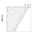
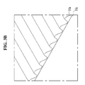
- FIGs. 3A to 3C are explanatory views of the corrugated board. More specifically, FIG. 3A is a lateral perspective view of a partial region of the corrugated board, FIG. 3B is a lateral perspective view of the corrugated board having no first cover layer, and FIG. 3C is a schematic sectional view of the corrugated board having no first cover layer.
- the corrugated board as exemplarily shown in FIG. 3A , includes an intermediate layer 10a provided with ridges, a first cover layer 10b that serves as a coating for an upper surface of the intermediate layer 10a, and a second cover layer 10c that serves as a coating for a lower surface of the intermediate layer 10a.
- the corrugated board may easily bend only in an arrangement direction of the plural ridges on the intermediate layer 10a.
- the corrugated board is more easily bendable when any one of the first and second cover layers 10b and 10c is removed.
- the corrugated board flexibly bends in an arrangement direction of the plural ridges when the first cover layer 10b is removed.
- FIG. 4 is a lateral perspective view showing a partial region of the bottom cover 10 according to the present invention.
- the bottom surface of the bottom surface 10 according to the present invention is formed of the corrugated board, and the ridges of the intermediate layer 10a are arranged in a longitudinal direction of the bottom cover 10.
- the bottom cover 10 has an opening 20 configured to expose the intermediate layer 10a.
- the opening 20 is acquired by patterning a portion of the first cover layer 10b constituting the rear side of the bottom cover 10.
- the opening 20 extends in a width direction of the bottom cover 10 to correspond to the curvature control unit 8.
- the bottom cover 10 flexibly bends upon receiving tensile force in a longitudinal direction thereof, but does not bend upon receiving tensile force in a width direction thereof.
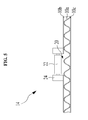
- FIG. 5 is a sectional view schematically showing the curvature control unit 8 shown in FIG. 2
- FIG. 6 is a view showing a configuration of a turnbuckle 22 shown in FIG. 5
- FIG. 7 is an explanatory view of a driving method of the curvature control unit 8.
- the curvature control unit 8 includes a plurality of tightening members 14 arranged along the opening 20 in a width direction of the bottom cover 10, a motor 12 that generates power, and a transmission member 16 configured to transmit power generated from the motor 12 to the plurality of tightening members 14.
- the tightening member 14 includes a pair of support pieces 24 spaced apart from each other with the opening 20 of the bottom cover 10 interposed therebetween, the support pieces 24 being fixed to the first cover layer 10b, and a turnbuckle 22 disposed between the pair of support pieces 24 to vary a distance between the pair of support pieces 24.
- the turnbuckle 22 includes a rotatable main body 22a, and a pair of screw rods 22b screwed to both sides of the main body 22a so as to be secured respectively to the pair of support pieces 24.
- each screw rod 22b is secured by being fastened with a bearing (30, see FIG. 8 ) of the support piece 24.
- the turnbuckle 22 may include the screw rod 22b only at one side of the rotatable main body 22a. In this case, one side of the main body 22a is pivotally rotatably connected to a first support piece, and the other end of the main body 22a is connected to a second support piece via the screw rod 22b.
- the turnbuckle 22 will be described as including the pair of screw rods 22b.
- the pair of screw rods 22b includes a first screw rod rotatably fastened to one side of the main body 22a, and a second screw rod rotatably fastened to the other side of the main body 22b.
- Each of the first and second screw rods is secured to either support piece 24.
- the first and second screw rods are moved in opposite directions away from the main body 22a when the main body 22a is rotated in a first direction. Then, the first and second screw rods approach each other toward the center of the main body 22a when the main body 22a is rotated in a second direction opposite to the first direction.
- the transmission member 16 configured to transmit power generated from the motor 12 to the plurality of tightening members 14 will be described in detail.
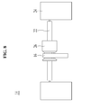
- FIG. 8 is a perspective view of the tightening member 14 according to a first embodiment of the present invention
- FIG. 9 is a view showing a configuration of the tightening member 14 connected to a timing belt 16.
- a pulley 26 and a timing belt 16 are provided to simultaneously drive a plurality of turnbuckles 22 using fewer motors 12.
- the transmission member 16 includes the timing belt 16 that transmits power generated from the motor 12 to the turnbuckles 22.
- the timing belt 16 is connected to a power shaft of the motor 12 and connects the plurality of turnbuckles 22 to one another.
- the tightening member 14 includes the pulley 26 to rotate the main body 22a of the turnbuckle 22 using power applied from the timing belt 16.
- the pulley 26 is secured to the main body 22a of the turnbuckle 22 and rotates the main body 22a of the turnbuckle 22 when the timing belt 16 is moved.
- the pulley 26 may be integrated with the main body 22a of the turnbuckle 22.
- a universal joint 18 is further provided to connect the power shaft of the motor 12 and the drive shaft of the timing belt 16 to each other.
- the universal joint 18 may be replaced by a coupling.
- FIG. 10 is a schematic plan view showing a rear surface of a curved display device according to a second embodiment of the present invention.
- FIG. 11 is an enlarged perspective view of a tightening member 34 shown in FIG. 10 .
- FIG. 12 is a schematic plan view showing a rear surface of a curved display device according to another embodiment of the present invention.
- the curved display device includes a wire 36 and a plurality of idlers 38 to simultaneously drive a plurality of turnbuckles 40 using fewer motors 32, differently from that of the first embodiment.
- each of the plurality of tightening members 34 includes a pair of support pieces 42 and the turnbuckle 40 to vary a distance between the support pieces 34.
- the motor 32 is connected to the wire 36 and drives the plurality of tightening members 34.
- One motor 32 may be provided as exemplarily shown in FIG. 12 .
- the wire 36 is connected to a power shaft of the motor 32 and connects the turnbuckles 40 of the plurality of tightening members 34 to one another.
- the wire 36 is connected to a rack 44 and rotates a main body of the turnbuckle 40 in the form of a pinion gear.
- Each of the plurality of tightening members 34 includes the pair of support pieces 42 spaced apart from each other with an opening of the bottom cover 10 interposed therebetween, the support pieces 42 being fixed to the first cover layer 10b, and the turnbuckle 40 disposed between the pair of support pieces 42 to vary a distance between the pair of support pieces 42.
- the turnbuckle 40 takes the form of a pinion gear tooth-engaged with the rack 44.
- the plurality of idlers 38 serves not only to guide the wire 36, but also to maintain tensile force of the wire 36.
- the above-described second embodiment proposes a driving method as follows.
- the motor 32 is driven to pull the wire 36, and in turn the rack 44 connected to the wire 36 rotates the main body of the turnbuckle 40 in the form of a pinion gear. Thereby, a distance between the pair of neighboring support pieces 42 varies, causing variation in the curvature of the bottom cover 10.
- the present invention proposes a bottom cover formed of a corrugated board, and a curvature control unit provided at a rear surface of the bottom cover to apply tensile force to the surface of the bottom cover. Accordingly, the present invention may vary curvature of the bottom cover to provide a display panel with a curved surface or flat surface in response to user need.
Landscapes
- Engineering & Computer Science (AREA)
- Physics & Mathematics (AREA)
- Theoretical Computer Science (AREA)
- General Physics & Mathematics (AREA)
- Computer Hardware Design (AREA)
- General Engineering & Computer Science (AREA)
- Nonlinear Science (AREA)
- Crystallography & Structural Chemistry (AREA)
- Chemical & Material Sciences (AREA)
- Optics & Photonics (AREA)
- Human Computer Interaction (AREA)
- Mathematical Physics (AREA)
- Devices For Indicating Variable Information By Combining Individual Elements (AREA)
- Electroluminescent Light Sources (AREA)
Abstract
Description
- This application claims the benefit of Korean Patent Application No.
10-2013-0091136, filed on, July 31, 2013 - The present invention relates to a curved display device and a method of controlling curvature thereof.
- Development of display technologies causes much use of flat panel display devices. Such flat panel display devices include Liquid Crystal Display (LCD) devices and Organic Light Emitting Diode (OLED) display devices, for example. Most of such flat panel display devices are used in TVs, laptop computers, MP3 players, cellular phones, and the like.
- Typically, flat panel display devices include a planar screen. By the way, flat panel display devices having a curved screen may be more suitable for users according to use purposes. Accordingly, as exemplarily shown in
FIG. 1 , a method of manufacturing a curved display device by coupling adisplay panel 2 to acasing member 4 having a specific curvature has been introduced in the related art. - The curved display device of the related art, however, makes it difficult for a user to vary curvature of the display panel according to desired situations because of mass production of the
casing member 4 having a fixed curvature. - Accordingly, the present invention is directed to a curved display device and a method of controlling curvature thereof that substantially obviate one or more problems due to limitations and disadvantages of the related art.
- An object of the present invention is to provide a curved display device and a method of controlling curvature thereof, which enable variation in the curvature of a display panel.
- Additional advantages, objects, and features of the invention will be set forth in part in the description which follows and in part will become apparent to those having ordinary skill in the art upon examination of the following or may be learned from practice of the invention. The objectives and other advantages of the invention may be realized and attained by the structure particularly pointed out in the written description and claims hereof as well as the appended drawings.
- To achieve these objects and other advantages and in accordance with the purpose of the disclosure, as embodied and broadly described herein, a curved display device includes a display panel, a bottom cover serving as a rear surface casing for the display panel, and at least one curvature control unit disposed on a rear surface of the bottom cover to control curvature of the bottom cover by applying tensile force to the rear surface of the bottom cover in a longitudinal direction of the bottom cover, wherein the bottom surface of the bottom cover is formed of a corrugated board including an intermediate layer provided with ridges, a first cover layer serving as a coating for an upper surface of the intermediate layer, and a second cover layer serving as a coating for a lower surface of the intermediate layer, and wherein the first cover layer has an opening configured to expose the intermediate layer to correspond to the curvature control unit.
- The curvature control unit may include a plurality of tightening members arranged along the opening perforated in a width direction of the bottom cover, a motor configured to generate power, and a transmission member configured to transmit power generated from the motor to the plurality of tightening members.
- Each tightening member may include a pair of support pieces spaced apart from each other with the opening interposed therebetween, the support pieces being fixed to the first cover layer, and a turnbuckle disposed between the pair of support pieces to vary a distance between the pair of support pieces, and the turnbuckle may include a main body, and a pair of screw rods screwed to both sides of the main body so as to be secured respectively to the pair of support pieces.
- The transmission member may include a timing belt, and each tightening member may further include a pulley secured to the main body of the turnbuckle to transmit power provided from the timing belt to the main body.
- The curvature control unit may further include a universal joint or coupling configured to connect a power shaft of the motor and a drive shaft of the timing belt to each other.
- The transmission member may include a wire, and the main body of the turnbuckle may take the form of a pinion gear, and the turnbuckle may further include a rack connected to the wire to rotate the main body.
- The transmission member may further include a plurality of idlers configured to guide the wire and maintain tensile force of the wire.
- In accordance with another aspect of the invention, in a method of controlling curvature of a curved display device, the curved display device including a display panel, a bottom cover serving as a rear surface casing for the display panel, a bottom surface of the bottom cover being formed of a corrugated board including an intermediate layer provided with ridges, a first cover layer serving as a coating for an upper surface of the intermediate layer, and a second cover layer serving as a coating for a lower surface of the intermediate layer, and at least one curvature control unit disposed on the first cover layer that is a rear surface of the bottom cover, the first cover layer having an opening configured to expose the intermediate layer to correspond to the curvature control unit, the method includes controlling curvature of the bottom cover by applying tensile force in a longitudinal direction of the bottom cover using the curvature control unit.
- The curvature control unit may include a plurality of tightening members arranged along the opening perforated in a width direction of the bottom cover, a motor configured to generate power, and a transmission member configured to transmit power generated from the motor to the plurality of tightening members, each tightening member may include a pair of support pieces spaced apart from each other with the opening interposed therebetween, the support pieces being fixed to the first cover layer, and a turnbuckle disposed between the pair of support pieces to vary a distance between the pair of support pieces, and the turnbuckle may include a main body, and a pair of screw rods screwed to both sides of the main body so as to be secured respectively to the pair of support pieces.
- The method may further include rotating the main body of the turnbuckle in a first direction using the motor and the transmission member to increase a distance between the pair of support pieces, and rotating the main body of the turnbuckle in a second direction opposite to the first direction using the motor and the transmission member to reduce a distance between the pair of support pieces.
- It is to be understood that both the foregoing general description and the following detailed description of the present invention are exemplary and explanatory and are intended to provide further explanation of the invention as claimed.
- The accompanying drawings, which are included to provide a further understanding of the disclosure and are incorporated in and constitute a part of this application, illustrate embodiment(s) of the invention and together with the description serve to explain the principle of the invention. In the drawings:
-
FIG. 1 is an explanatory view of a curved display device of the related art; -
FIG. 2 is a schematic plan view showing a rear surface of a curved display device according to an embodiment of the present invention; -
FIGs. 3A to 3C are explanatory views of a corrugated board; -
FIG. 4 is a lateral perspective view showing a partial region of abottom cover 10 according to the present invention; -
FIG. 5 is a sectional view schematically showing a curvature control unit 8 shown inFIG. 2 ; -
FIG. 6 is a view showing a configuration of aturnbuckle 22 shown inFIG. 5 ; -
FIG. 7 is an explanatory view of a driving method of the curvature control unit 8; -
FIG. 8 is a perspective view of a tighteningmember 14 according to a first embodiment of the present invention; -
FIG. 9 is a view showing a configuration of the tighteningmember 14 connected to atiming belt 16; -
FIG. 10 is a schematic plan view showing a rear surface of a curved display device according to a second embodiment of the present invention; -
FIG. 11 is an enlarged perspective view of a tighteningmember 34 shown inFIG. 10 ; and -
FIG. 12 is a schematic plan view showing a rear surface of a curved display device according to another embodiment of the present invention. - Hereinafter, a curved display device and a method of controlling curvature thereof according to an embodiment of the present invention will be described in detail with reference to the accompanying drawings.
- For reference, a curved display device according to the present invention basically includes a display panel that displays an image. The display panel may be a liquid crystal display panel or organic light emitting diode panel. A substrate of the display panel may be formed of a glass substrate or flexible material.
-
FIG. 2 is a schematic plan view showing a rear surface of a curved display device according to an embodiment of the present invention. - The curved display device exemplarily shown in
FIG. 2 includes abottom cover 10 that serves as a rear surface casing for a display panel (not shown), and at least one curvature control unit 8 disposed at a rear surface of thebottom cover 10. - The curvature control unit 8 is configured to apply tensile force in a longitudinal direction of the
bottom cover 10, thereby varying curvature of thebottom cover 10. Therefore, according to the present invention, a user may vary curvature of the display panel according to desired situations, and the display panel has a curved surface or flat surface according to curvature of thebottom cover 10. - The
bottom cover 10 is configured to receive the display panel. The curvature control unit 8 causes thebottom cover 10 to be deformed to a specific curvature, thereby varying curvature of the display panel. To this end, thebottom cover 10 is formed of a corrugated board such that a bottom surface configured to receive the display panel is easily bendable in a given direction (e.g., longitudinal direction). -
FIGs. 3A to 3C are explanatory views of the corrugated board. More specifically,FIG. 3A is a lateral perspective view of a partial region of the corrugated board,FIG. 3B is a lateral perspective view of the corrugated board having no first cover layer, andFIG. 3C is a schematic sectional view of the corrugated board having no first cover layer. - For reference, the corrugated board, as exemplarily shown in
FIG. 3A , includes anintermediate layer 10a provided with ridges, afirst cover layer 10b that serves as a coating for an upper surface of theintermediate layer 10a, and asecond cover layer 10c that serves as a coating for a lower surface of theintermediate layer 10a. - With the above-described configuration, the corrugated board may easily bend only in an arrangement direction of the plural ridges on the
intermediate layer 10a. In particular, the corrugated board is more easily bendable when any one of the first andsecond cover layers FIGs. 3B and3C , the corrugated board flexibly bends in an arrangement direction of the plural ridges when thefirst cover layer 10b is removed. -
FIG. 4 is a lateral perspective view showing a partial region of thebottom cover 10 according to the present invention. - Referring to
FIG. 4 , the bottom surface of thebottom surface 10 according to the present invention is formed of the corrugated board, and the ridges of theintermediate layer 10a are arranged in a longitudinal direction of thebottom cover 10. - The
bottom cover 10 has anopening 20 configured to expose theintermediate layer 10a. Theopening 20 is acquired by patterning a portion of thefirst cover layer 10b constituting the rear side of thebottom cover 10. Theopening 20 extends in a width direction of thebottom cover 10 to correspond to the curvature control unit 8. - Accordingly, the
bottom cover 10 flexibly bends upon receiving tensile force in a longitudinal direction thereof, but does not bend upon receiving tensile force in a width direction thereof. -
FIG. 5 is a sectional view schematically showing the curvature control unit 8 shown inFIG. 2 , andFIG. 6 is a view showing a configuration of a turnbuckle 22 shown inFIG. 5 .FIG. 7 is an explanatory view of a driving method of the curvature control unit 8. - Referring to
FIGs. 2 and5 , the curvature control unit 8 includes a plurality of tighteningmembers 14 arranged along theopening 20 in a width direction of thebottom cover 10, amotor 12 that generates power, and atransmission member 16 configured to transmit power generated from themotor 12 to the plurality of tighteningmembers 14. - The tightening
member 14 includes a pair ofsupport pieces 24 spaced apart from each other with theopening 20 of thebottom cover 10 interposed therebetween, thesupport pieces 24 being fixed to thefirst cover layer 10b, and a turnbuckle 22 disposed between the pair ofsupport pieces 24 to vary a distance between the pair ofsupport pieces 24. - The
turnbuckle 22, as exemplarily shown inFIG. 6 , includes a rotatablemain body 22a, and a pair ofscrew rods 22b screwed to both sides of themain body 22a so as to be secured respectively to the pair ofsupport pieces 24. Here, eachscrew rod 22b is secured by being fastened with a bearing (30, seeFIG. 8 ) of thesupport piece 24. Alternatively, differently from illustration ofFIG. 6 , theturnbuckle 22 may include thescrew rod 22b only at one side of the rotatablemain body 22a. In this case, one side of themain body 22a is pivotally rotatably connected to a first support piece, and the other end of themain body 22a is connected to a second support piece via thescrew rod 22b. Hereinafter, theturnbuckle 22 will be described as including the pair ofscrew rods 22b. - More specifically, the pair of
screw rods 22b includes a first screw rod rotatably fastened to one side of themain body 22a, and a second screw rod rotatably fastened to the other side of themain body 22b. Each of the first and second screw rods is secured to eithersupport piece 24. - In operation of the above-described
turnbuckle 22, the first and second screw rods are moved in opposite directions away from themain body 22a when themain body 22a is rotated in a first direction. Then, the first and second screw rods approach each other toward the center of themain body 22a when themain body 22a is rotated in a second direction opposite to the first direction. - According to the present invention, as exemplarily shown in
FIG. 7 , it is possible to increase a distance between the pair ofsupport pieces 24 by rotating themain body 22a of the turnbuckle 22 in the first direction using themotor 12 and thetransmission member 16. This causes thebottom cover 10, to which the pair ofsupport pieces 24 is fixed, to bend by a specific curvature. Also, according to the present invention, it is possible to reduce a distance between the pair ofsupport pieces 24 by rotating themain body 22a of the turnbuckle 22 in the second direction using themotor 12 and thetransmission member 16. This causes gradual reduction in the curvature of thebottom cover 10 to which the pair ofsupport pieces 24 is fixed. - Hereinafter, the
transmission member 16 configured to transmit power generated from themotor 12 to the plurality of tighteningmembers 14 will be described in detail. -
FIG. 8 is a perspective view of the tighteningmember 14 according to a first embodiment of the present invention, andFIG. 9 is a view showing a configuration of the tighteningmember 14 connected to atiming belt 16. - Referring to
FIGs. 8 and9 , in the first embodiment, apulley 26 and atiming belt 16 are provided to simultaneously drive a plurality ofturnbuckles 22 usingfewer motors 12. - More specifically, the
transmission member 16 includes thetiming belt 16 that transmits power generated from themotor 12 to the turnbuckles 22. Thetiming belt 16 is connected to a power shaft of themotor 12 and connects the plurality ofturnbuckles 22 to one another. - Meanwhile, the tightening
member 14 includes thepulley 26 to rotate themain body 22a of the turnbuckle 22 using power applied from thetiming belt 16. Thepulley 26 is secured to themain body 22a of theturnbuckle 22 and rotates themain body 22a of the turnbuckle 22 when thetiming belt 16 is moved. Thepulley 26 may be integrated with themain body 22a of theturnbuckle 22. - When the
bottom cover 10 bends via driving of theturnbuckle 22, the power shaft of themotor 12 may be spaced apart from a drive shaft of thetiming belt 16. Accordingly, in the first embodiment, as exemplarily shown inFIG. 2 , auniversal joint 18 is further provided to connect the power shaft of themotor 12 and the drive shaft of thetiming belt 16 to each other. The universal joint 18 may be replaced by a coupling. -
FIG. 10 is a schematic plan view showing a rear surface of a curved display device according to a second embodiment of the present invention.FIG. 11 is an enlarged perspective view of a tighteningmember 34 shown inFIG. 10 .FIG. 12 is a schematic plan view showing a rear surface of a curved display device according to another embodiment of the present invention. - The curved display device according to the second embodiment includes a
wire 36 and a plurality ofidlers 38 to simultaneously drive a plurality ofturnbuckles 40 usingfewer motors 32, differently from that of the first embodiment. - More specifically, in the second embodiment, as exemplarily shown in
FIGs. 10 and11 , at least onemotor 32, thewire 36 configured to transmit power generated from themotor 32 to a plurality of tighteningmembers 34, and the plurality ofidlers 38 are provided, and each of the plurality of tighteningmembers 34 includes a pair ofsupport pieces 42 and the turnbuckle 40 to vary a distance between thesupport pieces 34. - The
motor 32 is connected to thewire 36 and drives the plurality of tighteningmembers 34. Onemotor 32 may be provided as exemplarily shown inFIG. 12 . - The
wire 36 is connected to a power shaft of themotor 32 and connects theturnbuckles 40 of the plurality of tighteningmembers 34 to one another. Thewire 36 is connected to arack 44 and rotates a main body of the turnbuckle 40 in the form of a pinion gear. - Each of the plurality of tightening
members 34 includes the pair ofsupport pieces 42 spaced apart from each other with an opening of thebottom cover 10 interposed therebetween, thesupport pieces 42 being fixed to thefirst cover layer 10b, and the turnbuckle 40 disposed between the pair ofsupport pieces 42 to vary a distance between the pair ofsupport pieces 42. Here, theturnbuckle 40 takes the form of a pinion gear tooth-engaged with therack 44. - The plurality of
idlers 38 serves not only to guide thewire 36, but also to maintain tensile force of thewire 36. - The above-described second embodiment proposes a driving method as follows.
- The
motor 32 is driven to pull thewire 36, and in turn therack 44 connected to thewire 36 rotates the main body of the turnbuckle 40 in the form of a pinion gear. Thereby, a distance between the pair of neighboringsupport pieces 42 varies, causing variation in the curvature of thebottom cover 10. - As is apparent from the above description, the present invention proposes a bottom cover formed of a corrugated board, and a curvature control unit provided at a rear surface of the bottom cover to apply tensile force to the surface of the bottom cover. Accordingly, the present invention may vary curvature of the bottom cover to provide a display panel with a curved surface or flat surface in response to user need.
- It will be apparent that, although the preferred embodiments have been shown and described above, the invention is not limited to the above-described specific embodiments, and various modifications and variations can be made by those skilled in the art without departing from the gist of the appended claims. Thus, it is intended that the modifications and variations should not be understood independently of the technical sprit or prospect of the invention.
Claims (10)
- A curved display device comprising:a display panel;a bottom cover serving as a rear surface casing for the display panel; andat least one curvature control unit disposed on a rear surface of the bottom cover to control curvature of the bottom cover by applying tensile force to the rear surface of the bottom cover in a longitudinal direction of the bottom cover,wherein the bottom surface of the bottom cover is formed of a corrugated board including an intermediate layer provided with ridges, a first cover layer serving as a coating for an upper surface of the intermediate layer, and a second cover layer serving as a coating for a lower surface of the intermediate layer, andwherein the first cover layer has an opening configured to expose the intermediate layer to correspond to the curvature control unit.
- The device according to claim 1, wherein the curvature control unit includes:a plurality of tightening members arranged along the opening perforated in a width direction of the bottom cover;a motor configured to generate power; anda transmission member configured to transmit power generated from the motor to the plurality of tightening members.
- The device according to claim 2, wherein each tightening member includes:a pair of support pieces spaced apart from each other with the opening interposed therebetween, the support pieces being fixed to the first cover layer; anda turnbuckle disposed between the pair of support pieces to vary a distance between the pair of support pieces, andwherein the turnbuckle includes a main body, and a pair of screw rods screwed to both sides of the main body so as to be secured respectively to the pair of support pieces.
- The device according to claim 3, wherein the transmission member includes a timing belt, and
wherein each tightening member further includes a pulley secured to the main body of the turnbuckle to transmit power provided from the timing belt to the main body. - The device according to claim 4, wherein the curvature control unit further includes a universal joint or coupling configured to connect a power shaft of the motor and a drive shaft of the timing belt to each other.
- The device according to claim 3, wherein the transmission member includes a wire, and
wherein the main body of the turnbuckle takes the form of a pinion gear, and the turnbuckle further includes a rack connected to the wire to rotate the main body. - The device according to claim 6, wherein the transmission member further includes a plurality of idlers configured to guide the wire and maintain tensile force of the wire.
- A method of controlling curvature of a curved display device, the curved display device comprising a display panel, a bottom cover serving as a rear surface casing for the display panel, a bottom surface of the bottom cover being formed of a corrugated board including an intermediate layer provided with ridges, a first cover layer serving as a coating for an upper surface of the intermediate layer, and a second cover layer serving as a coating for a lower surface of the intermediate layer, and at least one curvature control unit disposed on the first cover layer that is a rear surface of the bottom cover, the first cover layer having an opening configured to expose the intermediate layer to correspond to the curvature control unit,
wherein the method comprises controlling curvature of the bottom cover by applying tensile force in a longitudinal direction of the bottom cover using the curvature control unit. - The method according to claim 8, wherein the curvature control unit includes:a plurality of tightening members arranged along the opening perforated in a width direction of the bottom cover;a motor configured to generate power; anda transmission member configured to transmit power generated from the motor to the plurality of tightening members,wherein each tightening member includes:a pair of support pieces spaced apart from each other with the opening interposed therebetween, the support pieces being fixed to the first cover layer; anda turnbuckle disposed between the pair of support pieces to vary a distance between the pair of support pieces, andwherein the turnbuckle includes a main body, and a pair of screw rods screwed to both sides of the main body so as to be secured respectively to the pair of support pieces.
- The method according to claim 9, further comprising:rotating the main body of the turnbuckle in a first direction using the motor and the transmission member to increase a distance between the pair of support pieces; androtating the main body of the turnbuckle in a second direction opposite to the first direction using the motor and the transmission member to reduce a distance between the pair of support pieces.
Applications Claiming Priority (1)
| Application Number | Priority Date | Filing Date | Title |
|---|---|---|---|
| KR1020130091136A KR102081112B1 (en) | 2013-07-31 | 2013-07-31 | Curved display device and method of controlling curvature thereof |
Publications (2)
| Publication Number | Publication Date |
|---|---|
| EP2833234A1 true EP2833234A1 (en) | 2015-02-04 |
| EP2833234B1 EP2833234B1 (en) | 2015-09-16 |
Family
ID=49876353
Family Applications (1)
| Application Number | Title | Priority Date | Filing Date |
|---|---|---|---|
| EP13196027.0A Not-in-force EP2833234B1 (en) | 2013-07-31 | 2013-12-06 | Curved display device and method of controlling curvature thereof |
Country Status (6)
| Country | Link |
|---|---|
| US (1) | US9058758B2 (en) |
| EP (1) | EP2833234B1 (en) |
| JP (1) | JP5857027B2 (en) |
| KR (1) | KR102081112B1 (en) |
| CN (1) | CN104347005B (en) |
| TW (1) | TWI510730B (en) |
Families Citing this family (79)
| Publication number | Priority date | Publication date | Assignee | Title |
|---|---|---|---|---|
| US9286812B2 (en) * | 2011-06-07 | 2016-03-15 | Microsoft Technology Licensing, Llc | Flexible display extendable assembly |
| USD778249S1 (en) * | 2013-04-08 | 2017-02-07 | Lg Electronics Inc. | Television receiver |
| USD778248S1 (en) * | 2013-04-08 | 2017-02-07 | Lg Electronics Inc. | Television receiver |
| KR102023015B1 (en) * | 2013-06-04 | 2019-09-19 | 엘지전자 주식회사 | Wall mounting type flexible display |
| KR20150012982A (en) * | 2013-07-25 | 2015-02-04 | 삼성전자주식회사 | Display apparatus and control method for the same |
| KR102265333B1 (en) * | 2013-11-28 | 2021-06-16 | 삼성전자주식회사 | Display apparatus and control method for the same |
| WO2015102472A1 (en) * | 2014-01-06 | 2015-07-09 | Samsung Electronics Co., Ltd. | Display apparatus |
| EP2940552B1 (en) * | 2014-04-29 | 2020-04-22 | LG Display Co., Ltd. | Adjustable display device |
| KR101565088B1 (en) * | 2014-04-30 | 2015-11-02 | 삼성전자주식회사 | Display panel, display panel design method and recording medium thereof |
| CN104006358A (en) * | 2014-06-17 | 2014-08-27 | 深圳市华星光电技术有限公司 | Curvature-adjustable backboard and application thereof |
| KR20160000298A (en) * | 2014-06-24 | 2016-01-04 | 삼성전자주식회사 | Display apparatus |
| KR102293491B1 (en) * | 2014-07-23 | 2021-08-27 | 삼성디스플레이 주식회사 | Display apparatus |
| KR20160016334A (en) * | 2014-08-05 | 2016-02-15 | 삼성전자주식회사 | Display apparatus |
| KR20160016333A (en) * | 2014-08-05 | 2016-02-15 | 삼성전자주식회사 | Display apparatus |
| USD743705S1 (en) * | 2014-08-07 | 2015-11-24 | II Ronald L. Cisler | Curved panoramic picture frame |
| CN104217650B (en) * | 2014-09-18 | 2019-09-27 | 青岛海信电器股份有限公司 | TV set with adjustable rear shell and curvature |
| USD768629S1 (en) * | 2014-10-07 | 2016-10-11 | Samsung Electronics Co., Ltd. | Monitor |
| KR20160050689A (en) * | 2014-10-30 | 2016-05-11 | 삼성전자주식회사 | Display apparatus and Method for controlling the display apparatus |
| CN104318869B (en) * | 2014-10-31 | 2017-01-18 | 京东方科技集团股份有限公司 | Flexible display device |
| KR102308645B1 (en) | 2014-12-29 | 2021-10-05 | 삼성전자주식회사 | User termincal device and methods for controlling the user termincal device thereof |
| WO2016108439A1 (en) | 2014-12-29 | 2016-07-07 | Samsung Electronics Co., Ltd. | Foldable device and method of controlling the same |
| US20160191837A1 (en) * | 2014-12-29 | 2016-06-30 | Samsung Electronics Co., Ltd. | Display apparatus and display method |
| KR20160096739A (en) * | 2015-02-05 | 2016-08-17 | 삼성디스플레이 주식회사 | Display device |
| USD776666S1 (en) * | 2015-02-05 | 2017-01-17 | Neonode Inc. | Curved light guide frame |
| CN104751744B (en) * | 2015-03-02 | 2017-07-21 | 联想(北京)有限公司 | A kind of method of adjustment and electronic equipment |
| KR102354505B1 (en) * | 2015-03-03 | 2022-01-21 | 삼성디스플레이 주식회사 | Wearable display device |
| US9756744B2 (en) * | 2015-03-12 | 2017-09-05 | International Business Machines Corporation | Controlling rigidity of flexible displays |
| CN104683719B (en) | 2015-03-18 | 2017-10-31 | 合肥鑫晟光电科技有限公司 | Curved-surface display device and curved-surface display method |
| KR20160116803A (en) * | 2015-03-31 | 2016-10-10 | 삼성전자주식회사 | Manufacturing Method of chassis and Display Apparatus having the same |
| US9857832B2 (en) | 2015-06-23 | 2018-01-02 | Samsung Electronics Co., Ltd. | Foldable electronic apparatus having display panel with variable curvature |
| USD783611S1 (en) * | 2015-07-01 | 2017-04-11 | Lg Electronics Inc. | Monitor |
| USD783612S1 (en) * | 2015-07-01 | 2017-04-11 | Lg Electronics Inc. | Monitor |
| KR20170005535A (en) * | 2015-07-06 | 2017-01-16 | 삼성전자주식회사 | Curved display apparatus |
| CN106708171B (en) * | 2015-07-21 | 2020-03-24 | 联想(北京)有限公司 | Connecting device and electronic equipment |
| JP6467599B2 (en) * | 2015-08-31 | 2019-02-13 | 株式会社Nsc | Display device |
| US10485100B2 (en) | 2015-09-30 | 2019-11-19 | Semiconductor Energy Laboratory Co., Ltd. | Circuit board and display system |
| CN105206181B (en) * | 2015-10-09 | 2018-02-16 | 武汉华星光电技术有限公司 | The long-range adjustable curved-surface display device of curvature |
| US10374857B2 (en) * | 2015-10-30 | 2019-08-06 | Telefonaktiebolaget L M Ericsson (Publ) | Transmitting and receiving reference signals |
| KR101760262B1 (en) | 2015-11-04 | 2017-07-21 | 삼성전자주식회사 | Display apparatus and control method for the same |
| CN105390069B (en) * | 2015-12-09 | 2018-06-22 | 深圳市华星光电技术有限公司 | Curved-surface display device |
| USD825490S1 (en) * | 2015-12-16 | 2018-08-14 | Shenzhen Royole Technologies Co., Ltd. | Switch |
| KR102483559B1 (en) * | 2015-12-28 | 2023-01-02 | 엘지디스플레이 주식회사 | Display device |
| KR102429119B1 (en) * | 2015-12-30 | 2022-08-05 | 엘지디스플레이 주식회사 | Display device |
| CN105578091B (en) * | 2016-01-06 | 2018-11-30 | 深圳创维-Rgb电子有限公司 | It is a kind of can right and wrong conversion flexible screen and television set |
| CN105681707B (en) * | 2016-01-06 | 2018-05-18 | 深圳创维-Rgb电子有限公司 | A kind of flexible display screen and its television set |
| KR20170087998A (en) | 2016-01-21 | 2017-08-01 | 삼성디스플레이 주식회사 | Display device and controlling method for curvature of the same |
| KR102504727B1 (en) * | 2016-04-18 | 2023-02-28 | 엘지전자 주식회사 | Display apparatus |
| USD816671S1 (en) * | 2016-08-30 | 2018-05-01 | Samsung Electronics Co., Ltd. | Monitor for computer |
| USD817956S1 (en) * | 2016-08-31 | 2018-05-15 | Samsung Electronics Co., Ltd. | Monitor for computer |
| USD816672S1 (en) * | 2016-08-31 | 2018-05-01 | Samsung Electronics Co., Ltd. | Monitor for computer |
| USD818468S1 (en) * | 2016-08-31 | 2018-05-22 | Samsung Electronics Co., Ltd. | Monitor for computer |
| USD817328S1 (en) * | 2016-08-31 | 2018-05-08 | Samsung Electronics Co., Ltd. | Monitor for computer |
| USD827643S1 (en) | 2016-08-31 | 2018-09-04 | Samsung Electronics Co., Ltd. | Monitor for computer |
| USD817957S1 (en) * | 2016-08-31 | 2018-05-15 | Samsung Electronics Co., Ltd. | Monitor for computer |
| KR102614599B1 (en) * | 2016-11-07 | 2023-12-18 | 삼성디스플레이 주식회사 | Rollable display apparatus |
| KR102565140B1 (en) * | 2016-11-28 | 2023-08-08 | 엘지디스플레이 주식회사 | Plastic substrate and Display device including the same |
| CN106952580B (en) * | 2017-02-17 | 2019-04-26 | 上海摩软通讯技术有限公司 | A kind of method of adjustment and device of the display area of the flexible display screen of terminal |
| US10712892B2 (en) * | 2017-04-26 | 2020-07-14 | Sensel, Inc. | Pre-loading a resistive touch sensor device via lamination of differently curved surfaces |
| KR102391216B1 (en) * | 2017-10-30 | 2022-04-27 | 엘지디스플레이 주식회사 | Display device |
| CN108302290B (en) * | 2018-01-12 | 2019-07-26 | 惠州市华星光电技术有限公司 | Variable curve supporting structure |
| KR102482409B1 (en) * | 2018-08-21 | 2022-12-28 | 삼성디스플레이 주식회사 | Display device |
| KR102593717B1 (en) * | 2018-08-31 | 2023-10-24 | 엘지디스플레이 주식회사 | Display device |
| US10720123B2 (en) | 2018-10-05 | 2020-07-21 | International Business Machines Corporation | Self-adjusting curved display screen |
| KR102612785B1 (en) * | 2018-12-20 | 2023-12-13 | 엘지전자 주식회사 | Display device |
| WO2021132777A1 (en) * | 2019-12-27 | 2021-07-01 | 엘지전자 주식회사 | Display device |
| US20230040067A1 (en) * | 2020-01-06 | 2023-02-09 | Lg Electronics Inc. | Display device |
| WO2021201309A1 (en) * | 2020-03-30 | 2021-10-07 | 엘지전자 주식회사 | Electronic device comprising flexible display |
| US12085995B2 (en) * | 2020-09-26 | 2024-09-10 | Intel Corporation | Dynamic curvature devices and peripherals |
| KR20220148997A (en) | 2021-04-29 | 2022-11-08 | 삼성디스플레이 주식회사 | Display device |
| KR20230018178A (en) | 2021-07-29 | 2023-02-07 | 엘지전자 주식회사 | Display device |
| US11538378B1 (en) * | 2021-08-17 | 2022-12-27 | International Business Machines Corporation | Digital content adjustment in a flexible display device |
| TWI801996B (en) * | 2021-09-08 | 2023-05-11 | 友達光電股份有限公司 | Mechanical design to switch curvature and display device |
| KR20230098969A (en) * | 2021-12-27 | 2023-07-04 | 엘지디스플레이 주식회사 | Display device |
| KR102782021B1 (en) * | 2022-01-13 | 2025-03-13 | 엘지전자 주식회사 | Display device |
| KR102831516B1 (en) * | 2022-01-13 | 2025-07-08 | 엘지전자 주식회사 | Display device and method thereof |
| USD1065343S1 (en) * | 2022-07-01 | 2025-03-04 | Tovis Co., Ltd. | Gaming monitor |
| KR20240102590A (en) * | 2022-12-26 | 2024-07-03 | 엘지디스플레이 주식회사 | Display device |
| USD1073673S1 (en) * | 2023-07-18 | 2025-05-06 | Lg Electronics Inc. | Monitor |
| KR20250102762A (en) * | 2023-12-28 | 2025-07-07 | 엘지디스플레이 주식회사 | Flexible display device |
Citations (6)
| Publication number | Priority date | Publication date | Assignee | Title |
|---|---|---|---|---|
| JP2008276035A (en) * | 2007-05-02 | 2008-11-13 | Seiko Epson Corp | Electronic equipment, display device and protective cover |
| US20100188422A1 (en) * | 2007-10-18 | 2010-07-29 | Fujitsu Limited | Display device and display system |
| JP2011027921A (en) * | 2009-07-23 | 2011-02-10 | Videocon Global Ltd | Movable focus type concave surface television |
| US20130114193A1 (en) * | 2011-11-08 | 2013-05-09 | Samsung Electronics Co., Ltd. | Flexible display apparatus |
| EP2610667A1 (en) * | 2011-12-30 | 2013-07-03 | Samsung Electronics Co., Ltd | Display device |
| EP2667247A1 (en) * | 2012-05-25 | 2013-11-27 | Samsung Electronics Co., Ltd | Liquid crystal display apparatus |
Family Cites Families (15)
| Publication number | Priority date | Publication date | Assignee | Title |
|---|---|---|---|---|
| JP3885246B2 (en) * | 1996-01-12 | 2007-02-21 | 松下電器産業株式会社 | Plasma display panel |
| JPH10268790A (en) | 1997-03-24 | 1998-10-09 | Seiko Epson Corp | LIQUID CRYSTAL DISPLAY PANEL HOLDER, LIQUID CRYSTAL DISPLAY USING THE SAME, ELECTRONIC APPARATUS USING THE LIQUID CRYSTAL DISPLAY DEVICE, CURABLE LIQUID CRYSTAL DISPLAY PANEL MANUFACTURING JIG AND METHOD FOR MANUFACTURING CURVED LIQUID CRYSTAL DISPLAY PANEL USING THE SAME |
| JP3980405B2 (en) | 2002-05-17 | 2007-09-26 | 株式会社東芝 | Image display device |
| JP2004061775A (en) * | 2002-07-26 | 2004-02-26 | Alps Electric Co Ltd | Active matrix type display device |
| JP4885430B2 (en) | 2004-05-21 | 2012-02-29 | 株式会社Nsc | Display device |
| JP2006023676A (en) | 2004-07-09 | 2006-01-26 | Pioneer Electronic Corp | Display-adjusting device and display device |
| JP2008197446A (en) | 2007-02-14 | 2008-08-28 | Toshiba Transport Eng Inc | Display device |
| JP5125640B2 (en) | 2008-03-14 | 2013-01-23 | 富士通株式会社 | Display device |
| JP2010078761A (en) * | 2008-09-25 | 2010-04-08 | Seiko Epson Corp | Display device and electronic equipment |
| CN101726905B (en) * | 2008-10-29 | 2013-09-18 | 上海天马微电子有限公司 | Method for manufacturing flat panel display device |
| KR101036618B1 (en) | 2009-02-16 | 2011-05-24 | 한국과학기술원 | Haptic feedback providing device of flexible display and its providing method |
| CN101915999A (en) | 2010-07-12 | 2010-12-15 | 深圳市华星光电技术有限公司 | Non-planar display module and back frame support structure thereof |
| US8787016B2 (en) | 2011-07-06 | 2014-07-22 | Apple Inc. | Flexible display devices |
| KR101401196B1 (en) * | 2011-12-19 | 2014-05-29 | 엘지전자 주식회사 | Display apparatus |
| JP5842602B2 (en) | 2011-12-26 | 2016-01-13 | 株式会社Joled | Curved display |
-
2013
- 2013-07-31 KR KR1020130091136A patent/KR102081112B1/en not_active Expired - Fee Related
- 2013-12-06 EP EP13196027.0A patent/EP2833234B1/en not_active Not-in-force
- 2013-12-16 US US14/107,181 patent/US9058758B2/en not_active Expired - Fee Related
- 2013-12-18 TW TW102147040A patent/TWI510730B/en not_active IP Right Cessation
- 2013-12-19 JP JP2013262519A patent/JP5857027B2/en not_active Expired - Fee Related
- 2013-12-19 CN CN201310703719.7A patent/CN104347005B/en not_active Expired - Fee Related
Patent Citations (6)
| Publication number | Priority date | Publication date | Assignee | Title |
|---|---|---|---|---|
| JP2008276035A (en) * | 2007-05-02 | 2008-11-13 | Seiko Epson Corp | Electronic equipment, display device and protective cover |
| US20100188422A1 (en) * | 2007-10-18 | 2010-07-29 | Fujitsu Limited | Display device and display system |
| JP2011027921A (en) * | 2009-07-23 | 2011-02-10 | Videocon Global Ltd | Movable focus type concave surface television |
| US20130114193A1 (en) * | 2011-11-08 | 2013-05-09 | Samsung Electronics Co., Ltd. | Flexible display apparatus |
| EP2610667A1 (en) * | 2011-12-30 | 2013-07-03 | Samsung Electronics Co., Ltd | Display device |
| EP2667247A1 (en) * | 2012-05-25 | 2013-11-27 | Samsung Electronics Co., Ltd | Liquid crystal display apparatus |
Also Published As
| Publication number | Publication date |
|---|---|
| TWI510730B (en) | 2015-12-01 |
| KR102081112B1 (en) | 2020-02-25 |
| EP2833234B1 (en) | 2015-09-16 |
| CN104347005B (en) | 2017-01-04 |
| CN104347005A (en) | 2015-02-11 |
| JP5857027B2 (en) | 2016-02-10 |
| US20150035812A1 (en) | 2015-02-05 |
| TW201504553A (en) | 2015-02-01 |
| US9058758B2 (en) | 2015-06-16 |
| JP2015031948A (en) | 2015-02-16 |
| KR20150015276A (en) | 2015-02-10 |
Similar Documents
| Publication | Publication Date | Title |
|---|---|---|
| US9058758B2 (en) | Curved display device and method of controlling curvature thereof | |
| KR102688120B1 (en) | Electronic device including flexible display | |
| US10701824B2 (en) | Bending module and folding display device | |
| CN104900153B (en) | foldable display device | |
| US9541952B2 (en) | Display apparatus | |
| CN104485055B (en) | Auxiliary spreading device for flexible screen | |
| WO2020006683A1 (en) | Support mechanism of flexible display screen and flexible display device | |
| CN105609001A (en) | Flexible display | |
| US20200221585A1 (en) | Slidable display device | |
| US20180341293A1 (en) | Display device | |
| KR20160083608A (en) | Foldable display apparatus | |
| KR20200049967A (en) | Display device | |
| CN110006739A (en) | Test equipment for flexible apparatus | |
| KR20170057500A (en) | Foldable display apparatus | |
| CN111383528A (en) | Display device | |
| KR102891636B1 (en) | Display device | |
| US9917266B2 (en) | Bendable device with a window top layer and a body having extendable bending region | |
| KR102751011B1 (en) | Display device | |
| KR102396761B1 (en) | display apparatus | |
| KR102415925B1 (en) | Display device | |
| KR102302702B1 (en) | Bendable display | |
| KR20200015876A (en) | Display device | |
| CN108327231B (en) | Bending device | |
| US12498078B2 (en) | Display device | |
| US10222831B2 (en) | Display apparatus |
Legal Events
| Date | Code | Title | Description |
|---|---|---|---|
| 17P | Request for examination filed |
Effective date: 20131206 |
|
| AK | Designated contracting states |
Kind code of ref document: A1 Designated state(s): AL AT BE BG CH CY CZ DE DK EE ES FI FR GB GR HR HU IE IS IT LI LT LU LV MC MK MT NL NO PL PT RO RS SE SI SK SM TR |
|
| AX | Request for extension of the european patent |
Extension state: BA ME |
|
| PUAI | Public reference made under article 153(3) epc to a published international application that has entered the european phase |
Free format text: ORIGINAL CODE: 0009012 |
|
| GRAP | Despatch of communication of intention to grant a patent |
Free format text: ORIGINAL CODE: EPIDOSNIGR1 |
|
| INTG | Intention to grant announced |
Effective date: 20150402 |
|
| GRAS | Grant fee paid |
Free format text: ORIGINAL CODE: EPIDOSNIGR3 |
|
| GRAA | (expected) grant |
Free format text: ORIGINAL CODE: 0009210 |
|
| AK | Designated contracting states |
Kind code of ref document: B1 Designated state(s): AL AT BE BG CH CY CZ DE DK EE ES FI FR GB GR HR HU IE IS IT LI LT LU LV MC MK MT NL NO PL PT RO RS SE SI SK SM TR |
|
| REG | Reference to a national code |
Ref country code: GB Ref legal event code: FG4D |
|
| REG | Reference to a national code |
Ref country code: CH Ref legal event code: EP |
|
| REG | Reference to a national code |
Ref country code: IE Ref legal event code: FG4D |
|
| REG | Reference to a national code |
Ref country code: AT Ref legal event code: REF Ref document number: 750271 Country of ref document: AT Kind code of ref document: T Effective date: 20151015 |
|
| REG | Reference to a national code |
Ref country code: DE Ref legal event code: R096 Ref document number: 602013003101 Country of ref document: DE |
|
| REG | Reference to a national code |
Ref country code: FR Ref legal event code: PLFP Year of fee payment: 3 |
|
| PG25 | Lapsed in a contracting state [announced via postgrant information from national office to epo] |
Ref country code: GR Free format text: LAPSE BECAUSE OF FAILURE TO SUBMIT A TRANSLATION OF THE DESCRIPTION OR TO PAY THE FEE WITHIN THE PRESCRIBED TIME-LIMIT Effective date: 20151217 Ref country code: LV Free format text: LAPSE BECAUSE OF FAILURE TO SUBMIT A TRANSLATION OF THE DESCRIPTION OR TO PAY THE FEE WITHIN THE PRESCRIBED TIME-LIMIT Effective date: 20150916 Ref country code: NO Free format text: LAPSE BECAUSE OF FAILURE TO SUBMIT A TRANSLATION OF THE DESCRIPTION OR TO PAY THE FEE WITHIN THE PRESCRIBED TIME-LIMIT Effective date: 20151216 Ref country code: FI Free format text: LAPSE BECAUSE OF FAILURE TO SUBMIT A TRANSLATION OF THE DESCRIPTION OR TO PAY THE FEE WITHIN THE PRESCRIBED TIME-LIMIT Effective date: 20150916 Ref country code: LT Free format text: LAPSE BECAUSE OF FAILURE TO SUBMIT A TRANSLATION OF THE DESCRIPTION OR TO PAY THE FEE WITHIN THE PRESCRIBED TIME-LIMIT Effective date: 20150916 |
|
| REG | Reference to a national code |
Ref country code: LT Ref legal event code: MG4D Ref country code: NL Ref legal event code: FP |
|
| REG | Reference to a national code |
Ref country code: AT Ref legal event code: MK05 Ref document number: 750271 Country of ref document: AT Kind code of ref document: T Effective date: 20150916 |
|
| PG25 | Lapsed in a contracting state [announced via postgrant information from national office to epo] |
Ref country code: RS Free format text: LAPSE BECAUSE OF FAILURE TO SUBMIT A TRANSLATION OF THE DESCRIPTION OR TO PAY THE FEE WITHIN THE PRESCRIBED TIME-LIMIT Effective date: 20150916 Ref country code: HR Free format text: LAPSE BECAUSE OF FAILURE TO SUBMIT A TRANSLATION OF THE DESCRIPTION OR TO PAY THE FEE WITHIN THE PRESCRIBED TIME-LIMIT Effective date: 20150916 Ref country code: SE Free format text: LAPSE BECAUSE OF FAILURE TO SUBMIT A TRANSLATION OF THE DESCRIPTION OR TO PAY THE FEE WITHIN THE PRESCRIBED TIME-LIMIT Effective date: 20150916 |
|
| PG25 | Lapsed in a contracting state [announced via postgrant information from national office to epo] |
Ref country code: SK Free format text: LAPSE BECAUSE OF FAILURE TO SUBMIT A TRANSLATION OF THE DESCRIPTION OR TO PAY THE FEE WITHIN THE PRESCRIBED TIME-LIMIT Effective date: 20150916 Ref country code: ES Free format text: LAPSE BECAUSE OF FAILURE TO SUBMIT A TRANSLATION OF THE DESCRIPTION OR TO PAY THE FEE WITHIN THE PRESCRIBED TIME-LIMIT Effective date: 20150916 Ref country code: IT Free format text: LAPSE BECAUSE OF FAILURE TO SUBMIT A TRANSLATION OF THE DESCRIPTION OR TO PAY THE FEE WITHIN THE PRESCRIBED TIME-LIMIT Effective date: 20150916 Ref country code: EE Free format text: LAPSE BECAUSE OF FAILURE TO SUBMIT A TRANSLATION OF THE DESCRIPTION OR TO PAY THE FEE WITHIN THE PRESCRIBED TIME-LIMIT Effective date: 20150916 Ref country code: CZ Free format text: LAPSE BECAUSE OF FAILURE TO SUBMIT A TRANSLATION OF THE DESCRIPTION OR TO PAY THE FEE WITHIN THE PRESCRIBED TIME-LIMIT Effective date: 20150916 Ref country code: IS Free format text: LAPSE BECAUSE OF FAILURE TO SUBMIT A TRANSLATION OF THE DESCRIPTION OR TO PAY THE FEE WITHIN THE PRESCRIBED TIME-LIMIT Effective date: 20160116 |
|
| PG25 | Lapsed in a contracting state [announced via postgrant information from national office to epo] |
Ref country code: RO Free format text: LAPSE BECAUSE OF FAILURE TO SUBMIT A TRANSLATION OF THE DESCRIPTION OR TO PAY THE FEE WITHIN THE PRESCRIBED TIME-LIMIT Effective date: 20150916 Ref country code: PT Free format text: LAPSE BECAUSE OF FAILURE TO SUBMIT A TRANSLATION OF THE DESCRIPTION OR TO PAY THE FEE WITHIN THE PRESCRIBED TIME-LIMIT Effective date: 20160118 Ref country code: PL Free format text: LAPSE BECAUSE OF FAILURE TO SUBMIT A TRANSLATION OF THE DESCRIPTION OR TO PAY THE FEE WITHIN THE PRESCRIBED TIME-LIMIT Effective date: 20150916 Ref country code: BE Free format text: LAPSE BECAUSE OF NON-PAYMENT OF DUE FEES Effective date: 20151231 Ref country code: AT Free format text: LAPSE BECAUSE OF FAILURE TO SUBMIT A TRANSLATION OF THE DESCRIPTION OR TO PAY THE FEE WITHIN THE PRESCRIBED TIME-LIMIT Effective date: 20150916 |
|
| REG | Reference to a national code |
Ref country code: DE Ref legal event code: R097 Ref document number: 602013003101 Country of ref document: DE |
|
| PLBE | No opposition filed within time limit |
Free format text: ORIGINAL CODE: 0009261 |
|
| STAA | Information on the status of an ep patent application or granted ep patent |
Free format text: STATUS: NO OPPOSITION FILED WITHIN TIME LIMIT |
|
| PG25 | Lapsed in a contracting state [announced via postgrant information from national office to epo] |
Ref country code: LU Free format text: LAPSE BECAUSE OF FAILURE TO SUBMIT A TRANSLATION OF THE DESCRIPTION OR TO PAY THE FEE WITHIN THE PRESCRIBED TIME-LIMIT Effective date: 20151206 Ref country code: MC Free format text: LAPSE BECAUSE OF FAILURE TO SUBMIT A TRANSLATION OF THE DESCRIPTION OR TO PAY THE FEE WITHIN THE PRESCRIBED TIME-LIMIT Effective date: 20150916 |
|
| 26N | No opposition filed |
Effective date: 20160617 |
|
| PG25 | Lapsed in a contracting state [announced via postgrant information from national office to epo] |
Ref country code: DK Free format text: LAPSE BECAUSE OF FAILURE TO SUBMIT A TRANSLATION OF THE DESCRIPTION OR TO PAY THE FEE WITHIN THE PRESCRIBED TIME-LIMIT Effective date: 20150916 |
|
| REG | Reference to a national code |
Ref country code: IE Ref legal event code: MM4A |
|
| PG25 | Lapsed in a contracting state [announced via postgrant information from national office to epo] |
Ref country code: IE Free format text: LAPSE BECAUSE OF NON-PAYMENT OF DUE FEES Effective date: 20151206 |
|
| PG25 | Lapsed in a contracting state [announced via postgrant information from national office to epo] |
Ref country code: SI Free format text: LAPSE BECAUSE OF FAILURE TO SUBMIT A TRANSLATION OF THE DESCRIPTION OR TO PAY THE FEE WITHIN THE PRESCRIBED TIME-LIMIT Effective date: 20150916 |
|
| REG | Reference to a national code |
Ref country code: FR Ref legal event code: PLFP Year of fee payment: 4 |
|
| PG25 | Lapsed in a contracting state [announced via postgrant information from national office to epo] |
Ref country code: BE Free format text: LAPSE BECAUSE OF FAILURE TO SUBMIT A TRANSLATION OF THE DESCRIPTION OR TO PAY THE FEE WITHIN THE PRESCRIBED TIME-LIMIT Effective date: 20150916 |
|
| PG25 | Lapsed in a contracting state [announced via postgrant information from national office to epo] |
Ref country code: BG Free format text: LAPSE BECAUSE OF FAILURE TO SUBMIT A TRANSLATION OF THE DESCRIPTION OR TO PAY THE FEE WITHIN THE PRESCRIBED TIME-LIMIT Effective date: 20150916 |
|
| PG25 | Lapsed in a contracting state [announced via postgrant information from national office to epo] |
Ref country code: HU Free format text: LAPSE BECAUSE OF FAILURE TO SUBMIT A TRANSLATION OF THE DESCRIPTION OR TO PAY THE FEE WITHIN THE PRESCRIBED TIME-LIMIT; INVALID AB INITIO Effective date: 20131206 Ref country code: CY Free format text: LAPSE BECAUSE OF FAILURE TO SUBMIT A TRANSLATION OF THE DESCRIPTION OR TO PAY THE FEE WITHIN THE PRESCRIBED TIME-LIMIT Effective date: 20150916 |
|
| REG | Reference to a national code |
Ref country code: CH Ref legal event code: PL |
|
| PG25 | Lapsed in a contracting state [announced via postgrant information from national office to epo] |
Ref country code: MT Free format text: LAPSE BECAUSE OF FAILURE TO SUBMIT A TRANSLATION OF THE DESCRIPTION OR TO PAY THE FEE WITHIN THE PRESCRIBED TIME-LIMIT Effective date: 20150916 |
|
| REG | Reference to a national code |
Ref country code: FR Ref legal event code: PLFP Year of fee payment: 5 |
|
| PG25 | Lapsed in a contracting state [announced via postgrant information from national office to epo] |
Ref country code: CH Free format text: LAPSE BECAUSE OF NON-PAYMENT OF DUE FEES Effective date: 20161231 Ref country code: LI Free format text: LAPSE BECAUSE OF NON-PAYMENT OF DUE FEES Effective date: 20161231 |
|
| PG25 | Lapsed in a contracting state [announced via postgrant information from national office to epo] |
Ref country code: SM Free format text: LAPSE BECAUSE OF FAILURE TO SUBMIT A TRANSLATION OF THE DESCRIPTION OR TO PAY THE FEE WITHIN THE PRESCRIBED TIME-LIMIT Effective date: 20150916 |
|
| PG25 | Lapsed in a contracting state [announced via postgrant information from national office to epo] |
Ref country code: MK Free format text: LAPSE BECAUSE OF FAILURE TO SUBMIT A TRANSLATION OF THE DESCRIPTION OR TO PAY THE FEE WITHIN THE PRESCRIBED TIME-LIMIT Effective date: 20150916 |
|
| REG | Reference to a national code |
Ref country code: FR Ref legal event code: PLFP Year of fee payment: 6 |
|
| PG25 | Lapsed in a contracting state [announced via postgrant information from national office to epo] |
Ref country code: AL Free format text: LAPSE BECAUSE OF FAILURE TO SUBMIT A TRANSLATION OF THE DESCRIPTION OR TO PAY THE FEE WITHIN THE PRESCRIBED TIME-LIMIT Effective date: 20150916 Ref country code: TR Free format text: LAPSE BECAUSE OF FAILURE TO SUBMIT A TRANSLATION OF THE DESCRIPTION OR TO PAY THE FEE WITHIN THE PRESCRIBED TIME-LIMIT Effective date: 20150916 |
|
| PGFP | Annual fee paid to national office [announced via postgrant information from national office to epo] |
Ref country code: NL Payment date: 20191022 Year of fee payment: 7 Ref country code: DE Payment date: 20191021 Year of fee payment: 7 |
|
| PGFP | Annual fee paid to national office [announced via postgrant information from national office to epo] |
Ref country code: FR Payment date: 20191023 Year of fee payment: 7 |
|
| PGFP | Annual fee paid to national office [announced via postgrant information from national office to epo] |
Ref country code: GB Payment date: 20191023 Year of fee payment: 7 |
|
| REG | Reference to a national code |
Ref country code: DE Ref legal event code: R119 Ref document number: 602013003101 Country of ref document: DE |
|
| REG | Reference to a national code |
Ref country code: NL Ref legal event code: MM Effective date: 20210101 |
|
| GBPC | Gb: european patent ceased through non-payment of renewal fee |
Effective date: 20201206 |
|
| PG25 | Lapsed in a contracting state [announced via postgrant information from national office to epo] |
Ref country code: NL Free format text: LAPSE BECAUSE OF NON-PAYMENT OF DUE FEES Effective date: 20210101 |
|
| PG25 | Lapsed in a contracting state [announced via postgrant information from national office to epo] |
Ref country code: FR Free format text: LAPSE BECAUSE OF NON-PAYMENT OF DUE FEES Effective date: 20201231 |
|
| PG25 | Lapsed in a contracting state [announced via postgrant information from national office to epo] |
Ref country code: GB Free format text: LAPSE BECAUSE OF NON-PAYMENT OF DUE FEES Effective date: 20201206 Ref country code: DE Free format text: LAPSE BECAUSE OF NON-PAYMENT OF DUE FEES Effective date: 20210701 |