EP2833233A1 - Intelligent terminal with wireless communication device capable of being replaced by user - Google Patents
Intelligent terminal with wireless communication device capable of being replaced by user Download PDFInfo
- Publication number
- EP2833233A1 EP2833233A1 EP12730141.4A EP12730141A EP2833233A1 EP 2833233 A1 EP2833233 A1 EP 2833233A1 EP 12730141 A EP12730141 A EP 12730141A EP 2833233 A1 EP2833233 A1 EP 2833233A1
- Authority
- EP
- European Patent Office
- Prior art keywords
- wireless communication
- communication device
- intelligent terminal
- user
- replacement
- Prior art date
- Legal status (The legal status is an assumption and is not a legal conclusion. Google has not performed a legal analysis and makes no representation as to the accuracy of the status listed.)
- Granted
Links
Images

Classifications
-
- H—ELECTRICITY
- H04—ELECTRIC COMMUNICATION TECHNIQUE
- H04B—TRANSMISSION
- H04B1/00—Details of transmission systems, not covered by a single one of groups H04B3/00 - H04B13/00; Details of transmission systems not characterised by the medium used for transmission
- H04B1/38—Transceivers, i.e. devices in which transmitter and receiver form a structural unit and in which at least one part is used for functions of transmitting and receiving
- H04B1/3816—Mechanical arrangements for accommodating identification devices, e.g. cards or chips; with connectors for programming identification devices
-
- G—PHYSICS
- G06—COMPUTING OR CALCULATING; COUNTING
- G06F—ELECTRIC DIGITAL DATA PROCESSING
- G06F1/00—Details not covered by groups G06F3/00 - G06F13/00 and G06F21/00
- G06F1/16—Constructional details or arrangements
- G06F1/1613—Constructional details or arrangements for portable computers
- G06F1/1633—Constructional details or arrangements of portable computers not specific to the type of enclosures covered by groups G06F1/1615 - G06F1/1626
- G06F1/1656—Details related to functional adaptations of the enclosure, e.g. to provide protection against EMI, shock, water, or to host detachable peripherals like a mouse or removable expansions units like PCMCIA cards, or to provide access to internal components for maintenance or to removable storage supports like CDs or DVDs, or to mechanically mount accessories
-
- G—PHYSICS
- G06—COMPUTING OR CALCULATING; COUNTING
- G06F—ELECTRIC DIGITAL DATA PROCESSING
- G06F1/00—Details not covered by groups G06F3/00 - G06F13/00 and G06F21/00
- G06F1/16—Constructional details or arrangements
- G06F1/1613—Constructional details or arrangements for portable computers
- G06F1/1633—Constructional details or arrangements of portable computers not specific to the type of enclosures covered by groups G06F1/1615 - G06F1/1626
- G06F1/1684—Constructional details or arrangements related to integrated I/O peripherals not covered by groups G06F1/1635 - G06F1/1675
- G06F1/1698—Constructional details or arrangements related to integrated I/O peripherals not covered by groups G06F1/1635 - G06F1/1675 the I/O peripheral being a sending/receiving arrangement to establish a cordless communication link, e.g. radio or infrared link, integrated cellular phone
-
- H—ELECTRICITY
- H04—ELECTRIC COMMUNICATION TECHNIQUE
- H04B—TRANSMISSION
- H04B1/00—Details of transmission systems, not covered by a single one of groups H04B3/00 - H04B13/00; Details of transmission systems not characterised by the medium used for transmission
- H04B1/38—Transceivers, i.e. devices in which transmitter and receiver form a structural unit and in which at least one part is used for functions of transmitting and receiving
- H04B1/3827—Portable transceivers
- H04B1/3888—Arrangements for carrying or protecting transceivers
Definitions
- the present invention relates to the technical field of intelligent terminals such as tablet computers, notebook computers and intelligent television (TV) sets, and more particularly, to an intelligent terminal that allows for replacement with a 3G or LTE wireless communication device when no free WiFi network resource is available.
- intelligent terminals such as tablet computers, notebook computers and intelligent television (TV) sets
- TV television
- the tablet computers are all made to be relatively thin, and for reasons of the cost, the thickness and the structure, it is usually difficult to dispose modules within the computer body that support wireless network accessing functions other than the WiFi (wireless fidelity) network accessing function.
- WiFi wireless fidelity
- the tablet computer when a user moves from an environment having WiFi network resources into an environment without WiFi network resources or from an environment having a 4G network into an environment having no 4G network, the tablet computer will become unable to access the Internet through wireless communication. This greatly degrades utility of the tablet computer.
- an ultra-thin wireless communication device which, as an optional accessory of a tablet computer, can be installed into the ultrathin body of the tablet computer so that the tablet computer can also support the other wireless network accessing functions beside the WiFi function.
- the present invention provides an intelligent terminal that allows for replacement of a wireless communication device by a user so as to improve the availability and the reliability of the product in use.
- An intelligent terminal that allows for replacement of a wireless communication device by a user, comprising an intelligent terminal body and a wireless communication device, a SIM card being installed in the wireless communication device, wherein: a slot for accommodating the wireless communication device to be inserted is disposed at a side of the intelligent terminal body, the wireless communication device is detachably inserted in the slot and connected to the intelligent terminal body via an interface, and the outer surface of the wireless communication device matches with the outer surface of the intelligent terminal body.
- the edge at the opening side of the slot partially extends inwards to the bottom surface of the intelligent terminal body to form a first notch for attaching and detaching the SIM card therethrough.
- the wireless communication device comprises a holder for fixing the SIM card, the holder is formed as a bridge-type fixing holder, and the wireless communication device provides a second notch in the sidewall of the front end thereof so that the SIM card can be plugged into and detached from a side of the wireless communication device when the wireless communication device is connected to the intelligent terminal body.
- the length of the first notch matches with the length of the SIM card, and the width of the first notch matches with the length of the holder.
- the wireless communication device comprises a metallic top cover, a plastic mid-frame, a metallic bottom cover and a interior printed circuit board (PCB), and the top cover serves as a shielding cover to cover regions of the PCB other than the SIM card and the holder thereof, and is connected to a ground of the PCB via a grounding shrapnel or a conductive foam.
- PCB printed circuit board
- the top cover and the bottom cover are both made of a stainless steel coils having a thickness of 0.1 mm ⁇ 0.4 mm and are formed through impact briquetting.
- an antenna connected with the PCB is disposed on the outer wall of the front end of the mid-frame.
- the intelligent terminal further comprises a back shell fitted over the bottom of the intelligent terminal with the periphery of the back shell covering the outer surface of the wireless communication device.
- the wireless communication device has a 3G chip or an LTE chip built therein, and an interface where the wireless communication device connects to the intelligent terminal body is an Mini PCI E interface.
- the intelligent terminal is a tablet computer.
- the intelligent terminal that allows for replacement of a wireless communication device by a user adopts a wireless communication device whose outer surface matches with an outer surface of an body of the intelligent terminal
- the wireless network accessing function of the ultrathin intelligent terminal e.g., a tablet computer
- this intelligent terminal can prevent the wireless network accessing device from being subjected to external impact and the consequent damage on the interface, so the availability and the reliability of the product in use are greatly improved.
- the detachable wireless communication device also makes it convenient for the user to choose different kinds of wireless network accessing devices freely.
- the intelligent terminal of the present invention refers to an ultra-thin intelligent terminal that supports a WiFi network accessing function free of charge such as a tablet computer, an intelligent TV set or the like.
- Fig. 1 is a schematic back view of the intelligent terminal of the present invention with a back shell thereof being removed.
- the intelligent terminal comprises an intelligent terminal body 100 and a wireless communication device 200.
- a SIM card 300 is disposed in the wireless communication device 200.
- a slot 110 is disposed in a side surface of the intelligent terminal body 100 to accommodate the wireless communication device 200 to be inserted therein.
- the wireless communication device 200 is connected to the intelligent terminal body 100 via an interface.
- An outer surface of the wireless communication device 200 matches with an outer surface of the intelligent terminal body 100; for example, the outer surface of the wireless communication device 200 is flush with that of the intelligent terminal body 100, forms a portion of the side surface or even a portion of the bottom surface of the intelligent terminal body 100, or extends beyond the outer surface of the intelligent terminal body 100.
- the tablet computer of the user When the user changes from an environment having WiFi network resources to an environment without WiFi network resources or from an environment having a 4G network to an environment having no 4G network, the tablet computer of the user will still be able to wirelessly connect to the Internet through the wireless communication device 200,which greatly improves utility of the tablet computer.
- the intelligent terminal that allows for replacement of a wireless communication device by a user according to the present invention adopts a wireless communication device whose outer surface matches with an outer surface of an shell of the intelligent terminal, so the wireless network accessing function of the ultra-thin intelligent terminal (e.g., a tablet computer) is ensured even when no WiFi or 4G network resources are available.Meanwhile, comparing with the external wireless network accessing devices which has protruding part, this intelligent terminal can prevent the wireless network accessing device from being subjected to external impact and the consequent damage on the interface, so the availability and the reliability of the product in use are greatly improved. Moreover, the detachable wireless communication device also makes it convenient for the user to choose different kinds of wireless network accessing devices freely.
- FIG. 2 is a schematic exploded view of the intelligent terminal of the present invention.
- the intelligent terminal further comprises a back shell 400 fitted over the bottom of the intelligent terminal body 100 with the periphery of the back shell 400 covering the outer surface of the wireless communication device 200. With the protection from the back shell 400, it becomes further less likely for the wireless communication device 200 to be damaged due to external impacts, and this completely ensures the availability and the reliability of the product in use.
- the edge at the opening side of the slot 110 partially extends inwards to the bottom surface of the intelligent terminal body 100 to form a first notch 120 for attaching or detaching the SIM card 300 therethrough.
- the SIM card 300 inserted in the intelligent terminal will be partially exposed from the surface of the intelligent terminal body 100 so that the SIM card 300 can be attached and detached without removing the wireless communication device 200. This can prevent frequent plugging and removal of the wireless communication device 200 to prolong the service life of the product.
- the wireless communication device 200 comprises a holder 220 for fixing the SIM card 300, which is optionally a bridge-type fixing holder; and a second notch 202 is disposed in the sidewall of the front end of the wireless communication device 200 so that the SIM card 300 can be plugged into or removed from the side surface of the wireless communication device 200 when the wireless communication device 200 is connected to the intelligent terminal body 100.
- the length of the first notch 120 matches with the length of the SIM card, and the width of the first notch 120 matches with the length of the holder 220,which helps to make the volume of the wireless communication device 200 even smaller.
- Fig. 3 is a schematic enlarged front perspective view of the wireless communication device used in the intelligent terminal of the present invention.
- Fig. 4 is a schematic enlarged back perspective view of the wireless communication device used in the intelligent terminal of the present invention.
- the wireless communication device 200 comprises a metallic top cover 240, a plastic mid-frame 250, a metallic bottom cover 260, and a interior printed circuit board (PCB) 210.
- the top cover 240 serves as a shielding cover to cover regions of the PCB 210 other than the SIM card 300 and the holder 220 thereof, and is connected to a ground of the PCB 210 via a grounding shrapnel or a conductive foam (not shown).
- the inner wall of the top cover 240 is connected to the ground of the PCB 210 via the grounding shrapnel or the conductive foam to improve the anti-static performance of the product.
- the grounding shrapnel or the conductive foam may be disposed at a corner of the PCB 210 to avoid occupation of the space on the PCB 210,which allows the wireless communication device to be made even smaller.
- the top cover 240 and the bottom cover 260 are both made of a stainless steel sheets or coiled material having a thickness of 0.1 mm ⁇ 0.4 mm and preferably 0.2 mm through impact briquetting.
- the metallic top cover 240 can serve as a shielding cover of the chip; and moreover, a plastic material can only be formed to have a wall-thickness of at least 0.8 mm, but a metal material can be formed to have a wall-thickness of 0.1 mm ⁇ 0.4 mm.
- the overall thickness of the product can be reduced by 1.2 mm.
- an antenna 270 connected with the PCB 210 is disposed on an outer wall of a front end of the mid-frame 250.
- the antenna 270 is disposed outwards to better receive the network signals; and by means of the plastic mid-frame 250, the antenna 270 can also be fully isolated from the metallic top cover 240 so as to minimize the influence of the stainless steel shell on the performances of the antenna 270.
- the antenna 270 includes not limited to a LDS (Laser Direct Structure) antenna formed on the outer wall of the front end of the mid-frame 250 through laser engraving and chemical plating, but also an FPC (Flexible Printed Circuit Board) antenna, and so on.
- LDS antenna is an antenna which is a three-dimensional (3D) perspective circuit having the electronical function,and is formed on the surface of the shell of the plastic formed by injection moduling by the methods of metallization ,such as laser engraving and chemical plating.
- the wireless communication device 200 may have a 3G chip or an LTE chip (not shown) built therein.
- the interface where the wireless communication device 200 connects to the intelligent terminal body may be formed solely as an Mini PCI E interface so that different kinds of wireless communication devices are connected with the intelligent terminal all through a sole kind of interface 230,which makes it convenient for the user to choose different kinds of wireless network accessing devices freely.
- the wireless communication device 200 provides a protruding portion that protrudes from the bottom surface of the wireless communication device 200 so that the ultra-thin wireless communication device 200 can be removed from the slot of the intelligent terminal body. Meanwhile, through disposition of the protruding portion 225, more space will be available for design of the LDS antenna so that a better signal transmission effect can be obtained for wireless network accessing.
Landscapes
- Engineering & Computer Science (AREA)
- Computer Hardware Design (AREA)
- General Engineering & Computer Science (AREA)
- Theoretical Computer Science (AREA)
- Human Computer Interaction (AREA)
- Physics & Mathematics (AREA)
- General Physics & Mathematics (AREA)
- Computer Networks & Wireless Communication (AREA)
- Signal Processing (AREA)
- Telephone Set Structure (AREA)
Abstract
Description
- The present invention relates to the technical field of intelligent terminals such as tablet computers, notebook computers and intelligent television (TV) sets, and more particularly, to an intelligent terminal that allows for replacement with a 3G or LTE wireless communication device when no free WiFi network resource is available.
- Nowadays, with widespread use and rapid development of tablet computers, more and more consumers prefer to use tablet computers rather than mobile phones to access the Internet because the tablet computers have larger screens than the mobile phones.
- However, the tablet computers are all made to be relatively thin, and for reasons of the cost, the thickness and the structure, it is usually difficult to dispose modules within the computer body that support wireless network accessing functions other than the WiFi (wireless fidelity) network accessing function.
- Therefore, when a user moves from an environment having WiFi network resources into an environment without WiFi network resources or from an environment having a 4G network into an environment having no 4G network, the tablet computer will become unable to access the Internet through wireless communication. This greatly degrades utility of the tablet computer.
- Accordingly, there is an urgent need for an ultra-thin wireless communication device which, as an optional accessory of a tablet computer, can be installed into the ultrathin body of the tablet computer so that the tablet computer can also support the other wireless network accessing functions beside the WiFi function.
- To solve the aforesaid technical problem, the present invention provides an intelligent terminal that allows for replacement of a wireless communication device by a user so as to improve the availability and the reliability of the product in use.
- The technical solution of the present invention is as follows.
- An intelligent terminal that allows for replacement of a wireless communication device by a user, comprising an intelligent terminal body and a wireless communication device, a SIM card being installed in the wireless communication device, wherein: a slot for accommodating the wireless communication device to be inserted is disposed at a side of the intelligent terminal body, the wireless communication device is detachably inserted in the slot and connected to the intelligent terminal body via an interface, and the outer surface of the wireless communication device matches with the outer surface of the intelligent terminal body.
- Preferably, the edge at the opening side of the slot partially extends inwards to the bottom surface of the intelligent terminal body to form a first notch for attaching and detaching the SIM card therethrough.
- Preferably, the wireless communication device comprises a holder for fixing the SIM card, the holder is formed as a bridge-type fixing holder, and the wireless communication device provides a second notch in the sidewall of the front end thereof so that the SIM card can be plugged into and detached from a side of the wireless communication device when the wireless communication device is connected to the intelligent terminal body.
- Preferably, the length of the first notch matches with the length of the SIM card, and the width of the first notch matches with the length of the holder.
- Preferably, the wireless communication device comprises a metallic top cover, a plastic mid-frame, a metallic bottom cover and a interior printed circuit board (PCB), and the top cover serves as a shielding cover to cover regions of the PCB other than the SIM card and the holder thereof, and is connected to a ground of the PCB via a grounding shrapnel or a conductive foam.
- Preferably, the top cover and the bottom cover are both made of a stainless steel coils having a thickness of 0.1 mm∼0.4 mm and are formed through impact briquetting.
- Preferably, an antenna connected with the PCB is disposed on the outer wall of the front end of the mid-frame.
- Preferably, the intelligent terminal further comprises a back shell fitted over the bottom of the intelligent terminal with the periphery of the back shell covering the outer surface of the wireless communication device.
- Preferably, the wireless communication device has a 3G chip or an LTE chip built therein, and an interface where the wireless communication device connects to the intelligent terminal body is an Mini PCI E interface.
- Preferably, the intelligent terminal is a tablet computer.
- Because the intelligent terminal that allows for replacement of a wireless communication device by a user adopts a wireless communication device whose outer surface matches with an outer surface of an body of the intelligent terminal, the wireless network accessing function of the ultrathin intelligent terminal (e.g., a tablet computer) is ensured even when no WiFi or 4G network resources are available, and this minimizes the consumer's cost. Meanwhile, comparing with the external wireless network accessing devices which has protruding part, this intelligent terminal can prevent the wireless network accessing device from being subjected to external impact and the consequent damage on the interface, so the availability and the reliability of the product in use are greatly improved. Moreover, the detachable wireless communication device also makes it convenient for the user to choose different kinds of wireless network accessing devices freely.
-
-
Fig. 1 is a schematic back view of an intelligent terminal of the present invention when a back shell thereof is removed. -
Fig. 2 is a schematic exploded view of the intelligent terminal of the present invention. -
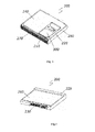
Fig. 3 is a schematic enlarged front perspective view of a wireless communication device used in the intelligent terminal of the present invention. -
Fig. 4 is a schematic enlarged back perspective view of the wireless communication device used in the intelligent terminal of the present invention. - Hereinbelow, particular implementations and embodiments of the present invention will be detailed with reference to the attached drawings. However, these embodiments described herein are only intended to explain the present invention but not to limit the present invention.
- The intelligent terminal of the present invention refers to an ultra-thin intelligent terminal that supports a WiFi network accessing function free of charge such as a tablet computer, an intelligent TV set or the like.
Fig. 1 is a schematic back view of the intelligent terminal of the present invention with a back shell thereof being removed. Specifically, the intelligent terminal comprises anintelligent terminal body 100 and awireless communication device 200. ASIM card 300 is disposed in thewireless communication device 200. Aslot 110 is disposed in a side surface of theintelligent terminal body 100 to accommodate thewireless communication device 200 to be inserted therein. Thewireless communication device 200 is connected to theintelligent terminal body 100 via an interface. An outer surface of thewireless communication device 200 matches with an outer surface of theintelligent terminal body 100; for example, the outer surface of thewireless communication device 200 is flush with that of theintelligent terminal body 100, forms a portion of the side surface or even a portion of the bottom surface of theintelligent terminal body 100, or extends beyond the outer surface of theintelligent terminal body 100. - When the user changes from an environment having WiFi network resources to an environment without WiFi network resources or from an environment having a 4G network to an environment having no 4G network, the tablet computer of the user will still be able to wirelessly connect to the Internet through the
wireless communication device 200,which greatly improves utility of the tablet computer. - As compared to the tablet computers in the prior art, the intelligent terminal that allows for replacement of a wireless communication device by a user according to the present invention adopts a wireless communication device whose outer surface matches with an outer surface of an shell of the intelligent terminal, so the wireless network accessing function of the ultra-thin intelligent terminal (e.g., a tablet computer) is ensured even when no WiFi or 4G network resources are available.Meanwhile, comparing with the external wireless network accessing devices which has protruding part, this intelligent terminal can prevent the wireless network accessing device from being subjected to external impact and the consequent damage on the interface, so the availability and the reliability of the product in use are greatly improved. Moreover, the detachable wireless communication device also makes it convenient for the user to choose different kinds of wireless network accessing devices freely.
- A preferred embodiment of the intelligent terminal of the present invention will be described with reference to
Fig. 2. FIG. 2 is a schematic exploded view of the intelligent terminal of the present invention. The intelligent terminal further comprises aback shell 400 fitted over the bottom of theintelligent terminal body 100 with the periphery of theback shell 400 covering the outer surface of thewireless communication device 200. With the protection from theback shell 400, it becomes further less likely for thewireless communication device 200 to be damaged due to external impacts, and this completely ensures the availability and the reliability of the product in use. - Further, the edge at the opening side of the
slot 110 partially extends inwards to the bottom surface of theintelligent terminal body 100 to form afirst notch 120 for attaching or detaching theSIM card 300 therethrough. Thus, theSIM card 300 inserted in the intelligent terminal will be partially exposed from the surface of theintelligent terminal body 100 so that theSIM card 300 can be attached and detached without removing thewireless communication device 200. This can prevent frequent plugging and removal of thewireless communication device 200 to prolong the service life of the product. - Preferably, the
wireless communication device 200 comprises aholder 220 for fixing theSIM card 300, which is optionally a bridge-type fixing holder; and asecond notch 202 is disposed in the sidewall of the front end of thewireless communication device 200 so that theSIM card 300 can be plugged into or removed from the side surface of thewireless communication device 200 when thewireless communication device 200 is connected to theintelligent terminal body 100. - Specifically, the length of the
first notch 120 matches with the length of the SIM card, and the width of thefirst notch 120 matches with the length of theholder 220,which helps to make the volume of thewireless communication device 200 even smaller. -
Fig. 3 is a schematic enlarged front perspective view of the wireless communication device used in the intelligent terminal of the present invention, and -
Fig. 4 is a schematic enlarged back perspective view of the wireless communication device used in the intelligent terminal of the present invention. As shown inFig. 3 and Fig. 4 , in order to make thewireless communication device 200 thinner to satisfy the design requirements of the ultra-thinintelligent terminal body 100, thewireless communication device 200 comprises ametallic top cover 240, aplastic mid-frame 250, ametallic bottom cover 260, and a interior printed circuit board (PCB) 210.Thetop cover 240 serves as a shielding cover to cover regions of thePCB 210 other than theSIM card 300 and theholder 220 thereof, and is connected to a ground of the PCB 210 via a grounding shrapnel or a conductive foam (not shown). - Specifically, the inner wall of the
top cover 240 is connected to the ground of the PCB 210 via the grounding shrapnel or the conductive foam to improve the anti-static performance of the product. The grounding shrapnel or the conductive foam may be disposed at a corner of the PCB 210 to avoid occupation of the space on the PCB 210,which allows the wireless communication device to be made even smaller. - Preferably, the
top cover 240 and thebottom cover 260 are both made of a stainless steel sheets or coiled material having a thickness of 0.1 mm∼0.4 mm and preferably 0.2 mm through impact briquetting. The reason why themetallic top cover 240 and themetallic bottom cover 260 are used as portions of thewireless communication device 200 lies in that, themetallic top cover 240 can serve as a shielding cover of the chip; and moreover, a plastic material can only be formed to have a wall-thickness of at least 0.8 mm, but a metal material can be formed to have a wall-thickness of 0.1 mm∼0.4 mm. Taking a thickness of 0.2 mm of themetallic top cover 240 and themetallic bottom cover 260 as an example, the overall thickness of the product can be reduced by 1.2 mm. - As shown in
Fig. 3 , anantenna 270 connected with the PCB 210 is disposed on an outer wall of a front end of themid-frame 250. Theantenna 270 is disposed outwards to better receive the network signals; and by means of theplastic mid-frame 250, theantenna 270 can also be fully isolated from themetallic top cover 240 so as to minimize the influence of the stainless steel shell on the performances of theantenna 270. - Preferably, the
antenna 270 includes not limited to a LDS (Laser Direct Structure) antenna formed on the outer wall of the front end of the mid-frame 250 through laser engraving and chemical plating, but also an FPC (Flexible Printed Circuit Board) antenna, and so on. The so-called LDS antenna is an antenna which is a three-dimensional (3D) perspective circuit having the electronical function,and is formed on the surface of the shell of the plastic formed by injection moduling by the methods of metallization ,such as laser engraving and chemical plating. - As shown in
Fig. 4 , thewireless communication device 200 may have a 3G chip or an LTE chip (not shown) built therein. The interface where thewireless communication device 200 connects to the intelligent terminal body may be formed solely as an Mini PCI E interface so that different kinds of wireless communication devices are connected with the intelligent terminal all through a sole kind ofinterface 230,which makes it convenient for the user to choose different kinds of wireless network accessing devices freely. - Preferably, at the bottom of the front end thereof, the
wireless communication device 200 provides a protruding portion that protrudes from the bottom surface of thewireless communication device 200 so that the ultra-thinwireless communication device 200 can be removed from the slot of the intelligent terminal body. Meanwhile, through disposition of the protrudingportion 225, more space will be available for design of the LDS antenna so that a better signal transmission effect can be obtained for wireless network accessing. - It shall be appreciated that, what described above are only preferred embodiments of the present invention but are not intended to limit the scope of the present invention. Accordingly, additions, deletions, substitutions, alterations or modifications may be made by those of ordinary skill in the art within the spirits and principles of the present invention, and all these additions, deletions, substitutions, alterations or modifications shall also fall within the scope of the present invention.
Claims (16)
- An intelligent terminal that allows for replacement of a wireless communication device by a user, comprising an intelligent terminal body and a wireless communication device, a SIM card being installed in the wireless communication device, wherein:a slot for accommodating the wireless communication device to be inserted is disposed at a side of the intelligent terminal body;the wireless communication device is detachably inserted in the slot and connected to the intelligent terminal body via an interface;the outer surface of the wireless communication device matches with the outer surface of the intelligent terminal body;the edge at the opening side of the slot partially extends inwards to the bottom surface of the intelligent terminal body to form a first notch for attaching and detaching the SIM card therethrough;the wireless communication device comprises a holder for fixing the SIM card, and the holder is formed as a bridge-type fixing holder;the wireless communication device provides a second notch in the sidewall of the front end thereof so that the SIM card can be plugged into and detached from the side of the wireless communication device when the wireless communication device is connected to the intelligent terminal body; andthe length of the first notch matches with the length of the SIM card, and the width of the first notch matches with the length of the holder.
- The intelligent terminal that allows for replacement of a wireless communication device by a user of Claim 1, wherein the wireless communication device comprises a metallic top cover, a plastic mid-frame, a metallic bottom cover and a interior printed circuit board (PCB), and the top cover serves as a shielding cover to cover regions of the PCB other than the SIM card and the holder thereof, and is connected to a ground of the PCB via a grounding shrapnel or a conductive foam.
- The intelligent terminal that allows for replacement of a wireless communication device by a user of Claim 2, wherein the top cover and the bottom cover are both made of a stainless steel coils having a thickness of 0.1 mm∼0.4 mm and are formed through impact briquetting.
- The intelligent terminal that allows for replacement of a wireless communication device by a user of Claim 2, wherein an antenna connected to the PCB is disposed on the outer wall of the front end of the mid-frame.
- The intelligent terminal that allows for replacement of a wireless communication device by a user of Claim 1, further comprising a back shell fitted over the bottom of the intelligent terminal with the periphery of the back shell covering the outer surface of the wireless communication device.
- The intelligent terminal that allows for replacement of a wireless communication device by a user of Claim 1, wherein the wireless communication device has a 3G chip or an LTE chip built therein, and an interface where the wireless communication device connects to the intelligent terminal body is an Mini PCI E interface.
- The intelligent terminal that allows for replacement of a wireless communication device by a user of Claim 1, wherein the intelligent terminal is a tablet computer.
- An intelligent terminal that allows for replacement of a wireless communication device by a user, comprising an intelligent terminal body and a wireless communication device, a SIM card being installed in the wireless communication device, wherein:a slot for accommodating the wireless communication device to be inserted is disposed at a side of the intelligent terminal body;the wireless communication device is detachably inserted in the slot and connected to the intelligent terminal body via an interface; andthe outer surface of the wireless communication device matches with the outer surface of the intelligent terminal body.
- The intelligent terminal that allows for replacement of a wireless communication device by a user of Claim 8, wherein the edge at the opening side of the slot partially extends inwards to the bottom surface of the intelligent terminal body to form a first notch for attaching and detaching the SIM card therethrough.
- The intelligent terminal that allows for replacement of a wireless communication device by a user of Claim 9, wherein the wireless communication device comprises a holder for fixing the SIM card, and the holder is formed as a bridge-type fixing holder; and the wireless communication device provides a second notch in the sidewall of the front end thereof so that the SIM card can be plugged into and detached from a side of the wireless communication device when the wireless communication device is connected to the intelligent terminal body.
- The intelligent terminal that allows for replacement of a wireless communication device by a user of Claim 8, wherein the wireless communication device comprises a metallic top cover, a plastic mid-frame, a metallic bottom cover and a PCB disposed therein, and the top cover serves as a shielding cover to cover regions of the PCB other than the SIM card and the holder thereof, and is connected to a ground of the PCB via a grounding shrapnel or a conductive foam.
- The intelligent terminal that allows for replacement of a wireless communication device by a user of Claim 11, wherein the top cover and the bottom cover are both made of a stainless steel coils having a thickness of 0.1 mm∼0.4 mm and are formed through impact briquetting.
- The intelligent terminal that allows for replacement of a wireless communication device by a user of Claim 11, wherein an antenna connected with the PCB is disposed on the outer wall of the front end of the mid-frame.
- The intelligent terminal that allows for replacement of a wireless communication device by a user of Claim 8, further comprising a back shell fitted over the bottom of the intelligent terminal with the periphery of the back shell covering the outer surface of the wireless communication device.
- The intelligent terminal that allows for replacement of a wireless communication device by a user of Claim 8, wherein the wireless communication device has a 3G chip or an LTE chip built therein, and an interface where the wireless communication device connects to the intelligent terminal body is an Mini PCI E interface.
- The intelligent terminal that allows for replacement of a wireless communication device by a user of Claim 8, wherein the intelligent terminal is a tablet computer.
Applications Claiming Priority (2)
| Application Number | Priority Date | Filing Date | Title |
|---|---|---|---|
| CN201210095230.1A CN102622056B (en) | 2012-03-31 | 2012-03-31 | The intelligent terminal of the replaceable radio communication device of a kind of user |
| PCT/CN2012/075674 WO2013143213A1 (en) | 2012-03-31 | 2012-05-17 | Intelligent terminal with wireless communication device capable of being replaced by user |
Publications (3)
| Publication Number | Publication Date |
|---|---|
| EP2833233A1 true EP2833233A1 (en) | 2015-02-04 |
| EP2833233A4 EP2833233A4 (en) | 2015-11-25 |
| EP2833233B1 EP2833233B1 (en) | 2018-12-12 |
Family
ID=46562014
Family Applications (1)
| Application Number | Title | Priority Date | Filing Date |
|---|---|---|---|
| EP12730141.4A Active EP2833233B1 (en) | 2012-03-31 | 2012-05-17 | Intelligent terminal with wireless communication device capable of being replaced by user |
Country Status (5)
| Country | Link |
|---|---|
| US (1) | US9014756B2 (en) |
| EP (1) | EP2833233B1 (en) |
| CN (1) | CN102622056B (en) |
| ES (1) | ES2712629T3 (en) |
| WO (1) | WO2013143213A1 (en) |
Families Citing this family (16)
| Publication number | Priority date | Publication date | Assignee | Title |
|---|---|---|---|---|
| KR102013326B1 (en) * | 2012-08-29 | 2019-08-23 | 삼성전자주식회사 | A protection cover for slot and window of portable terminal |
| CN104049674B (en) * | 2013-03-11 | 2018-03-27 | 联想(北京)有限公司 | Electronic equipment and adapter |
| KR101334083B1 (en) * | 2013-09-06 | 2013-12-03 | 김한수 | Tablet computer |
| KR102347670B1 (en) * | 2014-08-25 | 2022-01-06 | 삼성전자주식회사 | Electronic decvice caes and electronic decvice having the same |
| CN104184857A (en) * | 2014-09-09 | 2014-12-03 | 王家城 | Intelligent separated SIM card clamping base device and communication method |
| KR102231232B1 (en) * | 2015-02-27 | 2021-03-23 | 삼성전자주식회사 | Antenna and electronic device having it |
| CN106375495B (en) * | 2015-07-24 | 2021-03-23 | 富士康(昆山)电脑接插件有限公司 | Electronic device |
| US9666841B1 (en) * | 2015-12-21 | 2017-05-30 | Ventus Networks Llc | Router having removable cellular communication module |
| CN105811074A (en) * | 2016-01-27 | 2016-07-27 | 宇龙计算机通信科技(深圳)有限公司 | Antenna system and mobile terminal |
| CN109525269B (en) * | 2018-09-06 | 2021-01-29 | 汉纳森(厦门)数据股份有限公司 | SIM card mounting structure and cloud bus data processing equipment |
| CN110286266A (en) * | 2019-07-16 | 2019-09-27 | 灏翰创科有限公司 | Smart integrated electricity meter and solar panel system adopting the intelligent integrated electricity meter |
| US12568327B2 (en) * | 2020-12-18 | 2026-03-03 | Skullcandy, Inc. | Portable electronic accessory systems and related devices |
| TWI754517B (en) * | 2021-01-07 | 2022-02-01 | 和碩聯合科技股份有限公司 | Electronic connector assembly and electronic connector thereof |
| CN114793123A (en) * | 2022-05-14 | 2022-07-26 | 郑州铁路职业技术学院 | An intelligent terminal with a user-replaceable wireless communication device |
| TWD230638S (en) * | 2023-05-25 | 2024-04-01 | 仁寶電腦工業股份有限公司 臺北市內湖區瑞光路581號及581之1號 (中華民國) | Notebook computer |
| TWI904561B (en) * | 2024-01-29 | 2025-11-11 | 啟碁科技股份有限公司 | Electronic device |
Family Cites Families (37)
| Publication number | Priority date | Publication date | Assignee | Title |
|---|---|---|---|---|
| US5061845A (en) * | 1990-04-30 | 1991-10-29 | Texas Instruments Incorporated | Memory card |
| FR2747847B1 (en) * | 1996-04-18 | 1998-07-03 | Itt Composants Instr | ELECTRONIC CONNECTION BOX, TO A PERSONAL COMPUTER, EQUIPPED WITH A CONNECTOR FOR A CHIP CARD |
| ES2263579T3 (en) * | 2000-07-18 | 2006-12-16 | Option | TELECOMMUNICATIONS CARD WITH INTEGRATED ANTENNA. |
| US6561851B2 (en) * | 2001-04-27 | 2003-05-13 | Sierra Wireless Inc. | Module interface for PC card |
| TW531077U (en) * | 2001-05-11 | 2003-05-01 | Quanta Comp Inc | Customer ID card connector with a card ejecting device |
| CN2566323Y (en) * | 2002-04-08 | 2003-08-13 | 华展科技股份有限公司 | wireless tablet |
| TW537466U (en) * | 2002-08-01 | 2003-06-11 | Handlink Technologies Inc | Portable network transmission device |
| EP1418527A1 (en) * | 2002-11-08 | 2004-05-12 | Motorola, Inc. | Multiple SIM card holding apparatus |
| KR100764120B1 (en) * | 2003-02-25 | 2007-10-09 | 다이니폰 인사츠 가부시키가이샤 | Sim reader/writer |
| US7445476B2 (en) * | 2004-09-02 | 2008-11-04 | Kyocera Corporation | Card for information equipment, and terminal for information equipment |
| US20060121941A1 (en) * | 2004-12-03 | 2006-06-08 | Shiflett Jamie C | SIM card retaining device |
| CN2834107Y (en) * | 2005-09-29 | 2006-11-01 | 刘召忠 | Mobile card shell structure |
| US7382625B2 (en) * | 2006-01-23 | 2008-06-03 | Sony Ericsson Mobile Communications Ab | Combination antenna and SIM card support structure |
| CN200997089Y (en) * | 2006-03-07 | 2007-12-26 | 联想(北京)有限公司 | Notebook computer of integrated cell phone |
| CN2891602Y (en) * | 2006-05-11 | 2007-04-18 | 杭州华为三康技术有限公司 | Fixing device and mini-type flash memory card fixing device |
| JP2008017440A (en) * | 2006-06-05 | 2008-01-24 | Matsushita Electric Ind Co Ltd | Modem card, modem card utilization system and terminal |
| US7941184B2 (en) * | 2006-11-10 | 2011-05-10 | Dell Products L.P. | Methods and systems for managing and/or tracking use of subscriber identity module components |
| CN101232545A (en) * | 2007-01-23 | 2008-07-30 | 台达电子工业股份有限公司 | Wireless communication device and communication assembly thereof |
| US20080182622A1 (en) * | 2007-01-25 | 2008-07-31 | Sierra Wireless, Inc. | Method and Apparatus for Implementing a SIM Card Onboard a PC Card |
| US7354285B1 (en) * | 2007-02-26 | 2008-04-08 | Inventec Corporation | Card insertion structure of electronic device |
| WO2008127706A1 (en) * | 2007-04-13 | 2008-10-23 | Interdigital Technology Corporation | Method and apparatus for integrating a soft mobile voip client in a cellular pc card |
| CN201115086Y (en) * | 2007-07-23 | 2008-09-10 | 中兴通讯股份有限公司 | A casing coupling mechanism and a wireless network card casing using the mechanism |
| CN101354600B (en) * | 2007-07-26 | 2012-01-04 | 大众电脑股份有限公司 | Notebook computer and electronic device module that can be combined with the notebook computer |
| CN201387608Y (en) * | 2009-03-30 | 2010-01-20 | 晶通信息(上海)有限公司 | Universal serial bus integrated module |
| CN201435476Y (en) * | 2009-05-13 | 2010-03-31 | 上海徕木电子股份有限公司 | Bridge-type SIM card holder |
| DE102009023640B4 (en) * | 2009-05-29 | 2011-06-16 | Bury Sp.Z.O.O | Handsfree in a vehicle |
| CN101909108B (en) * | 2009-06-04 | 2013-06-05 | 纬创资通股份有限公司 | Mobile communication device and combination of portable electronic device and mobile communication device |
| CN102111464A (en) * | 2009-12-28 | 2011-06-29 | 鸿富锦精密工业(深圳)有限公司 | Card assembly and electronic equipment with same |
| US8564965B2 (en) * | 2010-04-19 | 2013-10-22 | Apple Inc. | Compact ejectable component assemblies in electronic devices |
| CN201757873U (en) * | 2010-08-05 | 2011-03-09 | 华为终端有限公司 | Pcmcia device |
| US8649783B2 (en) * | 2010-09-22 | 2014-02-11 | Nuance Communications, Inc. | No-cost mobile device messaging, such as for provisioning an application on a mobile device |
| US8699216B2 (en) * | 2010-10-22 | 2014-04-15 | Xplore Technologies Corp. | Computer with door-mounted electronics |
| TWI435645B (en) * | 2011-01-31 | 2014-04-21 | D Link Corp | A set of routers that can be used with a mobile terminal device |
| JP2012160908A (en) * | 2011-01-31 | 2012-08-23 | Toshiba Corp | Receiver and transmitter |
| KR101798391B1 (en) * | 2011-05-19 | 2017-12-13 | 삼성전자 주식회사 | Apparatus and system for calibration of portable terminal |
| US8880040B2 (en) * | 2011-05-23 | 2014-11-04 | Microsoft Corporation | Mobile network operator identification |
| CN202583948U (en) * | 2012-03-31 | 2012-12-05 | 惠州Tcl移动通信有限公司 | Intelligent terminal with replaceable wireless communication device |
-
2012
- 2012-03-31 CN CN201210095230.1A patent/CN102622056B/en not_active Expired - Fee Related
- 2012-05-17 ES ES12730141T patent/ES2712629T3/en active Active
- 2012-05-17 US US13/521,338 patent/US9014756B2/en active Active
- 2012-05-17 EP EP12730141.4A patent/EP2833233B1/en active Active
- 2012-05-17 WO PCT/CN2012/075674 patent/WO2013143213A1/en not_active Ceased
Also Published As
| Publication number | Publication date |
|---|---|
| CN102622056B (en) | 2016-05-11 |
| US9014756B2 (en) | 2015-04-21 |
| ES2712629T3 (en) | 2019-05-14 |
| EP2833233B1 (en) | 2018-12-12 |
| CN102622056A (en) | 2012-08-01 |
| US20140038533A1 (en) | 2014-02-06 |
| WO2013143213A1 (en) | 2013-10-03 |
| EP2833233A4 (en) | 2015-11-25 |
Similar Documents
| Publication | Publication Date | Title |
|---|---|---|
| US9014756B2 (en) | Intelligent terminal that allows for replacement of a wireless communication device by a user | |
| CN206294254U (en) | Housing unit, dual camera module and mobile terminal | |
| US9647321B2 (en) | Antenna for portable device | |
| KR102086717B1 (en) | Cover including glass and electronic device using the same | |
| US8217853B2 (en) | Electrical connector assembly with antenna function | |
| US9318830B2 (en) | SIM card socket and terminal device including the same | |
| US9160826B2 (en) | Docking station for portable communication device | |
| US20140247547A1 (en) | Portable terminal having a wireless charging module | |
| EP2698868B1 (en) | Internal antenna of mobile terminal | |
| CN108470977A (en) | Antenna assembly, antenna device and electronic equipment | |
| US20140176387A1 (en) | Reducing rf energy leakage between battery and pcb | |
| CN107293847A (en) | Center, antenna module and electronic equipment | |
| US7889506B2 (en) | Function expansion datacard | |
| CN107394354A (en) | Backplanes, Front Cases, and Electronics | |
| EP2493013A2 (en) | Mobile broadband device | |
| CN103633436B (en) | A kind of antenna installation and there is the electronics of this antenna installation | |
| CN202583948U (en) | Intelligent terminal with replaceable wireless communication device | |
| CN108039582A (en) | Middle frame components, antenna components and electronic equipment | |
| EP2466987A1 (en) | Mobile communication terminal and mobile communication terminal housing set with an antenna | |
| CN204597099U (en) | A deck and electronic equipment | |
| US8289704B2 (en) | Electronic apparatus | |
| US20130017861A1 (en) | Antenna device for a portable terminal | |
| CN201118873Y (en) | Mobile communication terminal with Bluetooth antenna | |
| JP3128219U (en) | External multimedia wireless card | |
| CN219591676U (en) | Electronic equipment assembly and protective housing thereof |
Legal Events
| Date | Code | Title | Description |
|---|---|---|---|
| PUAI | Public reference made under article 153(3) epc to a published international application that has entered the european phase |
Free format text: ORIGINAL CODE: 0009012 |
|
| 17P | Request for examination filed |
Effective date: 20121011 |
|
| AK | Designated contracting states |
Kind code of ref document: A1 Designated state(s): AL AT BE BG CH CY CZ DE DK EE ES FI FR GB GR HR HU IE IS IT LI LT LU LV MC MK MT NL NO PL PT RO RS SE SI SK SM TR |
|
| AX | Request for extension of the european patent |
Extension state: BA ME |
|
| DAX | Request for extension of the european patent (deleted) | ||
| RA4 | Supplementary search report drawn up and despatched (corrected) |
Effective date: 20151026 |
|
| RIC1 | Information provided on ipc code assigned before grant |
Ipc: G06F 1/16 20060101AFI20151019BHEP Ipc: H04B 1/3816 20150101ALI20151019BHEP |
|
| STAA | Information on the status of an ep patent application or granted ep patent |
Free format text: STATUS: EXAMINATION IS IN PROGRESS |
|
| 17Q | First examination report despatched |
Effective date: 20180629 |
|
| GRAP | Despatch of communication of intention to grant a patent |
Free format text: ORIGINAL CODE: EPIDOSNIGR1 |
|
| STAA | Information on the status of an ep patent application or granted ep patent |
Free format text: STATUS: GRANT OF PATENT IS INTENDED |
|
| RIC1 | Information provided on ipc code assigned before grant |
Ipc: G06F 1/16 20060101AFI20180723BHEP Ipc: H04B 1/3888 20150101ALI20180723BHEP Ipc: H04B 1/3816 20150101ALI20180723BHEP |
|
| INTG | Intention to grant announced |
Effective date: 20180821 |
|
| GRAS | Grant fee paid |
Free format text: ORIGINAL CODE: EPIDOSNIGR3 |
|
| GRAA | (expected) grant |
Free format text: ORIGINAL CODE: 0009210 |
|
| STAA | Information on the status of an ep patent application or granted ep patent |
Free format text: STATUS: THE PATENT HAS BEEN GRANTED |
|
| AK | Designated contracting states |
Kind code of ref document: B1 Designated state(s): AL AT BE BG CH CY CZ DE DK EE ES FI FR GB GR HR HU IE IS IT LI LT LU LV MC MK MT NL NO PL PT RO RS SE SI SK SM TR |
|
| REG | Reference to a national code |
Ref country code: GB Ref legal event code: FG4D |
|
| REG | Reference to a national code |
Ref country code: CH Ref legal event code: EP |
|
| REG | Reference to a national code |
Ref country code: AT Ref legal event code: REF Ref document number: 1076842 Country of ref document: AT Kind code of ref document: T Effective date: 20181215 |
|
| REG | Reference to a national code |
Ref country code: DE Ref legal event code: R096 Ref document number: 602012054620 Country of ref document: DE |
|
| REG | Reference to a national code |
Ref country code: IE Ref legal event code: FG4D |
|
| REG | Reference to a national code |
Ref country code: NL Ref legal event code: MP Effective date: 20181212 |
|
| REG | Reference to a national code |
Ref country code: LT Ref legal event code: MG4D |
|
| PG25 | Lapsed in a contracting state [announced via postgrant information from national office to epo] |
Ref country code: LT Free format text: LAPSE BECAUSE OF FAILURE TO SUBMIT A TRANSLATION OF THE DESCRIPTION OR TO PAY THE FEE WITHIN THE PRESCRIBED TIME-LIMIT Effective date: 20181212 Ref country code: NO Free format text: LAPSE BECAUSE OF FAILURE TO SUBMIT A TRANSLATION OF THE DESCRIPTION OR TO PAY THE FEE WITHIN THE PRESCRIBED TIME-LIMIT Effective date: 20190312 Ref country code: BG Free format text: LAPSE BECAUSE OF FAILURE TO SUBMIT A TRANSLATION OF THE DESCRIPTION OR TO PAY THE FEE WITHIN THE PRESCRIBED TIME-LIMIT Effective date: 20190312 Ref country code: HR Free format text: LAPSE BECAUSE OF FAILURE TO SUBMIT A TRANSLATION OF THE DESCRIPTION OR TO PAY THE FEE WITHIN THE PRESCRIBED TIME-LIMIT Effective date: 20181212 Ref country code: FI Free format text: LAPSE BECAUSE OF FAILURE TO SUBMIT A TRANSLATION OF THE DESCRIPTION OR TO PAY THE FEE WITHIN THE PRESCRIBED TIME-LIMIT Effective date: 20181212 Ref country code: LV Free format text: LAPSE BECAUSE OF FAILURE TO SUBMIT A TRANSLATION OF THE DESCRIPTION OR TO PAY THE FEE WITHIN THE PRESCRIBED TIME-LIMIT Effective date: 20181212 |
|
| REG | Reference to a national code |
Ref country code: ES Ref legal event code: FG2A Ref document number: 2712629 Country of ref document: ES Kind code of ref document: T3 Effective date: 20190514 |
|
| REG | Reference to a national code |
Ref country code: AT Ref legal event code: MK05 Ref document number: 1076842 Country of ref document: AT Kind code of ref document: T Effective date: 20181212 |
|
| PG25 | Lapsed in a contracting state [announced via postgrant information from national office to epo] |
Ref country code: RS Free format text: LAPSE BECAUSE OF FAILURE TO SUBMIT A TRANSLATION OF THE DESCRIPTION OR TO PAY THE FEE WITHIN THE PRESCRIBED TIME-LIMIT Effective date: 20181212 Ref country code: SE Free format text: LAPSE BECAUSE OF FAILURE TO SUBMIT A TRANSLATION OF THE DESCRIPTION OR TO PAY THE FEE WITHIN THE PRESCRIBED TIME-LIMIT Effective date: 20181212 Ref country code: AL Free format text: LAPSE BECAUSE OF FAILURE TO SUBMIT A TRANSLATION OF THE DESCRIPTION OR TO PAY THE FEE WITHIN THE PRESCRIBED TIME-LIMIT Effective date: 20181212 Ref country code: GR Free format text: LAPSE BECAUSE OF FAILURE TO SUBMIT A TRANSLATION OF THE DESCRIPTION OR TO PAY THE FEE WITHIN THE PRESCRIBED TIME-LIMIT Effective date: 20190313 |
|
| PG25 | Lapsed in a contracting state [announced via postgrant information from national office to epo] |
Ref country code: NL Free format text: LAPSE BECAUSE OF FAILURE TO SUBMIT A TRANSLATION OF THE DESCRIPTION OR TO PAY THE FEE WITHIN THE PRESCRIBED TIME-LIMIT Effective date: 20181212 |
|
| PG25 | Lapsed in a contracting state [announced via postgrant information from national office to epo] |
Ref country code: PL Free format text: LAPSE BECAUSE OF FAILURE TO SUBMIT A TRANSLATION OF THE DESCRIPTION OR TO PAY THE FEE WITHIN THE PRESCRIBED TIME-LIMIT Effective date: 20181212 Ref country code: PT Free format text: LAPSE BECAUSE OF FAILURE TO SUBMIT A TRANSLATION OF THE DESCRIPTION OR TO PAY THE FEE WITHIN THE PRESCRIBED TIME-LIMIT Effective date: 20190412 Ref country code: CZ Free format text: LAPSE BECAUSE OF FAILURE TO SUBMIT A TRANSLATION OF THE DESCRIPTION OR TO PAY THE FEE WITHIN THE PRESCRIBED TIME-LIMIT Effective date: 20181212 |
|
| PG25 | Lapsed in a contracting state [announced via postgrant information from national office to epo] |
Ref country code: RO Free format text: LAPSE BECAUSE OF FAILURE TO SUBMIT A TRANSLATION OF THE DESCRIPTION OR TO PAY THE FEE WITHIN THE PRESCRIBED TIME-LIMIT Effective date: 20181212 Ref country code: IS Free format text: LAPSE BECAUSE OF FAILURE TO SUBMIT A TRANSLATION OF THE DESCRIPTION OR TO PAY THE FEE WITHIN THE PRESCRIBED TIME-LIMIT Effective date: 20190412 Ref country code: SM Free format text: LAPSE BECAUSE OF FAILURE TO SUBMIT A TRANSLATION OF THE DESCRIPTION OR TO PAY THE FEE WITHIN THE PRESCRIBED TIME-LIMIT Effective date: 20181212 Ref country code: EE Free format text: LAPSE BECAUSE OF FAILURE TO SUBMIT A TRANSLATION OF THE DESCRIPTION OR TO PAY THE FEE WITHIN THE PRESCRIBED TIME-LIMIT Effective date: 20181212 Ref country code: SK Free format text: LAPSE BECAUSE OF FAILURE TO SUBMIT A TRANSLATION OF THE DESCRIPTION OR TO PAY THE FEE WITHIN THE PRESCRIBED TIME-LIMIT Effective date: 20181212 |
|
| REG | Reference to a national code |
Ref country code: DE Ref legal event code: R097 Ref document number: 602012054620 Country of ref document: DE |
|
| PLBE | No opposition filed within time limit |
Free format text: ORIGINAL CODE: 0009261 |
|
| STAA | Information on the status of an ep patent application or granted ep patent |
Free format text: STATUS: NO OPPOSITION FILED WITHIN TIME LIMIT |
|
| PG25 | Lapsed in a contracting state [announced via postgrant information from national office to epo] |
Ref country code: DK Free format text: LAPSE BECAUSE OF FAILURE TO SUBMIT A TRANSLATION OF THE DESCRIPTION OR TO PAY THE FEE WITHIN THE PRESCRIBED TIME-LIMIT Effective date: 20181212 Ref country code: AT Free format text: LAPSE BECAUSE OF FAILURE TO SUBMIT A TRANSLATION OF THE DESCRIPTION OR TO PAY THE FEE WITHIN THE PRESCRIBED TIME-LIMIT Effective date: 20181212 Ref country code: SI Free format text: LAPSE BECAUSE OF FAILURE TO SUBMIT A TRANSLATION OF THE DESCRIPTION OR TO PAY THE FEE WITHIN THE PRESCRIBED TIME-LIMIT Effective date: 20181212 |
|
| 26N | No opposition filed |
Effective date: 20190913 |
|
| REG | Reference to a national code |
Ref country code: CH Ref legal event code: PL |
|
| PG25 | Lapsed in a contracting state [announced via postgrant information from national office to epo] |
Ref country code: MC Free format text: LAPSE BECAUSE OF FAILURE TO SUBMIT A TRANSLATION OF THE DESCRIPTION OR TO PAY THE FEE WITHIN THE PRESCRIBED TIME-LIMIT Effective date: 20181212 Ref country code: LI Free format text: LAPSE BECAUSE OF NON-PAYMENT OF DUE FEES Effective date: 20190531 Ref country code: CH Free format text: LAPSE BECAUSE OF NON-PAYMENT OF DUE FEES Effective date: 20190531 |
|
| REG | Reference to a national code |
Ref country code: BE Ref legal event code: MM Effective date: 20190531 |
|
| PG25 | Lapsed in a contracting state [announced via postgrant information from national office to epo] |
Ref country code: LU Free format text: LAPSE BECAUSE OF NON-PAYMENT OF DUE FEES Effective date: 20190517 |
|
| PG25 | Lapsed in a contracting state [announced via postgrant information from national office to epo] |
Ref country code: TR Free format text: LAPSE BECAUSE OF FAILURE TO SUBMIT A TRANSLATION OF THE DESCRIPTION OR TO PAY THE FEE WITHIN THE PRESCRIBED TIME-LIMIT Effective date: 20181212 |
|
| PG25 | Lapsed in a contracting state [announced via postgrant information from national office to epo] |
Ref country code: IE Free format text: LAPSE BECAUSE OF NON-PAYMENT OF DUE FEES Effective date: 20190517 |
|
| PG25 | Lapsed in a contracting state [announced via postgrant information from national office to epo] |
Ref country code: BE Free format text: LAPSE BECAUSE OF NON-PAYMENT OF DUE FEES Effective date: 20190531 |
|
| PG25 | Lapsed in a contracting state [announced via postgrant information from national office to epo] |
Ref country code: CY Free format text: LAPSE BECAUSE OF FAILURE TO SUBMIT A TRANSLATION OF THE DESCRIPTION OR TO PAY THE FEE WITHIN THE PRESCRIBED TIME-LIMIT Effective date: 20181212 |
|
| PG25 | Lapsed in a contracting state [announced via postgrant information from national office to epo] |
Ref country code: HU Free format text: LAPSE BECAUSE OF FAILURE TO SUBMIT A TRANSLATION OF THE DESCRIPTION OR TO PAY THE FEE WITHIN THE PRESCRIBED TIME-LIMIT; INVALID AB INITIO Effective date: 20120517 Ref country code: MT Free format text: LAPSE BECAUSE OF FAILURE TO SUBMIT A TRANSLATION OF THE DESCRIPTION OR TO PAY THE FEE WITHIN THE PRESCRIBED TIME-LIMIT Effective date: 20181212 |
|
| PG25 | Lapsed in a contracting state [announced via postgrant information from national office to epo] |
Ref country code: MK Free format text: LAPSE BECAUSE OF FAILURE TO SUBMIT A TRANSLATION OF THE DESCRIPTION OR TO PAY THE FEE WITHIN THE PRESCRIBED TIME-LIMIT Effective date: 20181212 |
|
| P01 | Opt-out of the competence of the unified patent court (upc) registered |
Effective date: 20230530 |
|
| PGFP | Annual fee paid to national office [announced via postgrant information from national office to epo] |
Ref country code: DE Payment date: 20250521 Year of fee payment: 14 |
|
| PGFP | Annual fee paid to national office [announced via postgrant information from national office to epo] |
Ref country code: ES Payment date: 20250627 Year of fee payment: 14 |
|
| PGFP | Annual fee paid to national office [announced via postgrant information from national office to epo] |
Ref country code: IT Payment date: 20250527 Year of fee payment: 14 |
|
| PGFP | Annual fee paid to national office [announced via postgrant information from national office to epo] |
Ref country code: FR Payment date: 20250528 Year of fee payment: 14 |
|
| PGFP | Annual fee paid to national office [announced via postgrant information from national office to epo] |
Ref country code: GB Payment date: 20260306 Year of fee payment: 15 |