EP2833221B1 - Silicon overcoil balance spring - Google Patents
Silicon overcoil balance spring Download PDFInfo
- Publication number
- EP2833221B1 EP2833221B1 EP14178831.5A EP14178831A EP2833221B1 EP 2833221 B1 EP2833221 B1 EP 2833221B1 EP 14178831 A EP14178831 A EP 14178831A EP 2833221 B1 EP2833221 B1 EP 2833221B1
- Authority
- EP
- European Patent Office
- Prior art keywords
- balance spring
- main body
- body portion
- overcoil
- outer portion
- Prior art date
- Legal status (The legal status is an assumption and is not a legal conclusion. Google has not performed a legal analysis and makes no representation as to the accuracy of the status listed.)
- Active
Links
Images



Classifications
-
- G—PHYSICS
- G04—HOROLOGY
- G04B—MECHANICALLY-DRIVEN CLOCKS OR WATCHES; MECHANICAL PARTS OF CLOCKS OR WATCHES IN GENERAL; TIME PIECES USING THE POSITION OF THE SUN, MOON OR STARS
- G04B17/00—Mechanisms for stabilising frequency
- G04B17/04—Oscillators acting by spring tension
- G04B17/06—Oscillators with hairsprings, e.g. balance
- G04B17/066—Manufacture of the spiral spring
-
- G—PHYSICS
- G04—HOROLOGY
- G04B—MECHANICALLY-DRIVEN CLOCKS OR WATCHES; MECHANICAL PARTS OF CLOCKS OR WATCHES IN GENERAL; TIME PIECES USING THE POSITION OF THE SUN, MOON OR STARS
- G04B17/00—Mechanisms for stabilising frequency
- G04B17/32—Component parts or constructional details, e.g. collet, stud, virole or piton
-
- G—PHYSICS
- G04—HOROLOGY
- G04B—MECHANICALLY-DRIVEN CLOCKS OR WATCHES; MECHANICAL PARTS OF CLOCKS OR WATCHES IN GENERAL; TIME PIECES USING THE POSITION OF THE SUN, MOON OR STARS
- G04B17/00—Mechanisms for stabilising frequency
- G04B17/32—Component parts or constructional details, e.g. collet, stud, virole or piton
- G04B17/325—Component parts or constructional details, e.g. collet, stud, virole or piton for fastening the hairspring in a fixed position, e.g. using a block
-
- G—PHYSICS
- G04—HOROLOGY
- G04D—APPARATUS OR TOOLS SPECIALLY DESIGNED FOR MAKING OR MAINTAINING CLOCKS OR WATCHES
- G04D3/00—Watchmakers' or watch-repairers' machines or tools for working materials
- G04D3/0002—Watchmakers' or watch-repairers' machines or tools for working materials for mechanical working other than with a lathe
- G04D3/0035—Watchmakers' or watch-repairers' machines or tools for working materials for mechanical working other than with a lathe for components of the regulating mechanism
- G04D3/0041—Watchmakers' or watch-repairers' machines or tools for working materials for mechanical working other than with a lathe for components of the regulating mechanism for coil-springs
-
- Y—GENERAL TAGGING OF NEW TECHNOLOGICAL DEVELOPMENTS; GENERAL TAGGING OF CROSS-SECTIONAL TECHNOLOGIES SPANNING OVER SEVERAL SECTIONS OF THE IPC; TECHNICAL SUBJECTS COVERED BY FORMER USPC CROSS-REFERENCE ART COLLECTIONS [XRACs] AND DIGESTS
- Y10—TECHNICAL SUBJECTS COVERED BY FORMER USPC
- Y10T—TECHNICAL SUBJECTS COVERED BY FORMER US CLASSIFICATION
- Y10T29/00—Metal working
- Y10T29/49—Method of mechanical manufacture
- Y10T29/49579—Watch or clock making
Definitions
- the present invention relates to a silicon based overcoil balance spring.
- the present invention relates a silicon overcoil spring and the method of manufacturing the same.
- the regulating assembly of a timepiece typically includes a balance wheel which is an inertia flywheel, and a balance spring which is a resonator. These two components determine the working quality and accuracy of a timepiece.
- the resonant frequency of the balance spring and the balance wheel system control the working and regulation of the timepiece movement.
- silicon is a non-magnetic material, which provides advantages in timepiece manufacturing.
- the first example (i) is directed to modifying the initial plane balance springs so that it becomes a balance spring occupying a plurality of planes.
- Breguet has manufactured a Breguet overcoil balance spring with silicon based material, whereby the balance spring is formed from two or more pieces as an assembled overcoil spring.
- the second example (ii) consists of two balance springs which are manufactured as a matched pair. They are arranged so that they oscillate against one another such that the centres of gravity of the two springs move outwards and inwards on opposing symmetrical paths as they oscillate, with a view having the cumulative centre of gravity of the two springs remain towards the centre of the arbor. As there are two balance springs in this oscillating system, this however results in more energy consumption.
- CH703272 A2 discloses a spiral spring made of silicon or silicon dioxide in which an elevation device is placed between an outer coil of the spiral spring and a terminal curve to form a Breguet hair spring.
- the present invention seeks to provide a balance spring which overcomes or minimizes at least some of the deficiencies as exhibited by those of the prior art.
- the present invention provides a method of producing unitary formed silicon balance spring having an overcoil portion for regulation of a mechanical timepiece, said method including the steps of:
- step (ii) may be effected incrementally in the direction towards over said main body portion and towards the plane of the main body portion. Between or during incremental steps of step (ii), the step (iii) may be effected.
- an oxidation step of at least the outer portion is effected prior to effecting step (ii), so as to remove or minimize stress concentration defects.
- the oxidation step includes exposure to a hydrogen fluoride solution.
- the method may include the step of twisting the outer portion through at least one 180° turn, wherein said at least one 180° turn is about the longitudinal axis of said outer portion, and where the outer portion is twisted in a region adjacent the outer turn of said main body portion.
- the stress relaxation process is performed at a temperature of greater than 500°C, more preferably at a temperature of greater than 700°C, and more preferably at a temperature of greater than 1100°C.
- the stress relaxation process is performed for at least 10 hours, more preferably for at least 20 hours, and more preferably for at least 30 hours.
- the balance spring is formed by way of a micro-fabrication technique, more preferably by way of a deep reactive ion etching (DRIE) technique.
- DRIE deep reactive ion etching
- the present invention provides a silicon based balance spring comprising:
- the balance spring is formed by way of a micro-fabrication technique, and more preferably by way of a deep reactive ion etching (DRIE) technique.
- DRIE deep reactive ion etching
- the present invention provides a planar silicon balance spring having a main body and an integrally formed overcoil portion so as to improve concentricity and isochronicity of such a spring when utilized in a timepiece.
- the balance spring includes an overcoil portion which achieves said improvement in concentricity and isochronicity which is integrally formed with the main body of the balance spring and extends from the periphery of the main body of the balance spring in an out of plane overcoil arrangement, and manufacturing process for the formation thereof.
- the present invention provides a method of manufacturing an overcoil balance spring, whereby the balance spring is formed from a silicon based material, which provides a unitary formed silicon overcoil balance spring, without the necessity of any connection unit, as required by the previously mentioned silicon overcoil balance spring made by Breguet, US,7950,847 .
- a balance spring is provided and unitary formed from a silicon based material, whereby the balance spring includes a main body portion and overcoil portion.
- the balance spring is initially formed and provided with all portions in a co-planar form, and is formed by micro-manufacturing techniques, including Photo Lithography and Deep reactive-ion etching (DRIE), whereby the main body portion, collet portion and overcoil portion are co-planar.
- micro-manufacturing techniques including Photo Lithography and Deep reactive-ion etching (DRIE), whereby the main body portion, collet portion and overcoil portion are co-planar.
- the overcoil portion is provided out of the plane and in accordance with overcoil portions of balance springs as utilized for increasing balance spring concentricity, whilst not comprising the mechanical integrity of the balance spring and without the necessity for a separate overcoil portion to be adjoined to the main body portion.
- the shape and configuration of portions of the balance spring may be modified by utilising thermal techniques, without compromising the requisite mechanical properties of the balance spring as required during use in a time piece.
- a method for producing a unitary formed silicon balance spring having an overcoil portion and a spring resulting therefrom whereby a balance spring is initially formed having a main body portion for providing restoration torque for regulation of a mechanical timepiece, and an outer portion for formation of an overcoil portion wherein the outer portion extends radially outward from an outermost turn of the main body portion.
- the main body portion and the outer portion are integrally formed from a silicon based material and are formed in a co-planar configuration.
- the outer portion is moved in a direction relative to said main body portion and out of the plane of said main body portion, and in a direction towards over said main body portion and towards the plane of the main body portion.
- a stress relaxation process is provided to the balance spring so as to relieve internal stresses induced within the balance spring, and upon movement of said outer portion into the plane of said main body portion, the outer portion is located in an overcoil configuration relative to said main body portion.
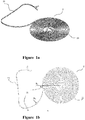
- a balance spring (2) having a main body portion (23) and an outer portion (22) prior to formation of an overcoil portion by a twisting movement is shown, and which has a "C" shape twisting region (21), whereby balance spring (2) is provided in an initial planar configuration and the outer portion (23) and main body portion (23) are integrally formed from a single material and are co-planar.
- the radius of the twisting region R 1 is slightly less than that of the second most outer coil R 2 . This design helps the twisting region (21) of final overcoil balance spring to follow the spiral of Archimedes, as seen from the top view.
- the shape of the original balance spring (2) as depicted transforms to an overcoil balance spring after the outer portion (22) being moved towards the plane of the body of the spring as depicted in Figure 4a and Figure 4b , whereby the outer portion (22) has formed an the overcoil portion by being been twisted 180° with respect to the adjacent the outermost turn of the main body of the spring.
- balance springs in accordance with the present invention are discussed below in relation to other embodiments.
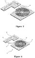
- FIG. 5 to 9 there is depicted the manner in which the balance spring of Figs 1a - 4b may be manipulated in accordance with the present invention, so as to provide a unitary formed overcoil balance spring.
- the balance spring (2) To achieve the movement and twisting process of the balance spring (2), it is necessary to utilize holders (61, 62) to grip the main body portion (23) and the outer portion (22). In the present embodiment, the outer portion (22) of the balance spring (2) needs to be flipped 180°, and this process requires high positioning accuracy.
- the first holder (61) is for holding all the centre coils of the main body portion (23) of the balance spring (2) except for the outer portion (22) including the outer portion as a "C" shape twisting region (21), and the second holder (62) is for holding the outer portion (22) of the balance spring (2).
- both of holders (61, 62) are formed from silicon by DRIE, and are oxidized by thermal oxidation.
- the first holder (61) for holding the centre coils of the main body portion (23) of the balance spring (2) is made with a series of trenches that are almost identical to the coils of the main body portion (23) of the balance spring (2).
- the trench is provided with a width that is slightly larger than the line width of the balance spring coil. This assists the balance spring centre coils of the main body portion (23) to maintain their original shape when torque is applied on the twisting region (21).
- the second holder (62) for holding the outer portion (22) is also provided with a trench sized so as to accommodate the coil outer portion.
- the same treatment as the first holder (61) applies on the second holder (62).
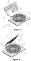
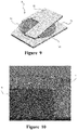
- FIGs 6 , 7 , 8 and 9 progressively depict the movement process of formation of the overcall portion. After the balance spring is moved into the overcoil shape as shown in Figure 9 , it is transferred into the annealing furnace together with the holders.
- the temperature should be lower than the oxidation temperature of silicon to avoid adhesion of the balance spring to the holders, and a temperature of 800°C is applicable for this application.
- the original balance spring (2) is provided as an overcoil balance spring.
- the annealing process may be provided in incremental steps with movement of the outer portion of the balance spring being in several steps.
- the balance spring outer portion (22) is twisted for 60°, as shown in Figure 7 , and then is annealed utilizing annealing conditions discussed below.
- the balance spring (2) changes into a twisted formation, as shown in Figure 2 .
- a second twisting for another 60° is then applied on the twisted balance spring (2), as shown in Figure 7 , and is annealed subsequently.
- This annealing process results in a further twisted balance spring (2), as shown in Figure 2 ,
- the final twisting for the rest 60° is performed on the twisted balance spring (2) after the previous two annealing processes, as shown in Figure 8 .
- the balance spring (2) and the holders (61, 62) are transferred into the furnace for the finale annealing. After removing the holders (61, 62), the silicon balance spring (2) transforms into overcoil balance spring permanently.
- Silicon is a brittle material at room temperature, however at temperatures between 520°C to 600°C the transition from brittle to ductile behaviour is obeyed. At temperatures higher than 700°C, it has been found that a requisite amount of plastic deformation is possible.
- a silicon balance spring is prepared prior to the oxidation process of the DRIE (deep reactive ion etching) etched silicon balance spring (2), the outer portion of the balance spring is twisted to another plane, and fixed by using a quartz fixture.
- DRIE deep reactive ion etching
- the oxidation temperature is preferably about 1100°C, and the temperature is kept fixed for approximately 30 hours. After the oxidation process it has been demonstrated that the shape of the outer portion of the balance spring is altered to the pre-set shape by the quartz fixture.
- the balance spring was immersed in a Hydrogen Fluoride (HF) solution.
- HF Hydrogen Fluoride
- the crystal structure changes during the oxidation process, which results in the permanent shape change.
- the outer portion of the balance spring to be twisted is to be regarded as a straight beam, with beam width of t and h , and beam length l .
- the twisting angle ⁇ is a function of the shear modulus , the polar moment inertia I p applied torque on the beam M t , and the beam length l .
- ⁇ / G ⁇ I p M t ⁇ l
- the maximum stress inside the balance spring coil is about 1.3GPa.
- the fracture stress for thin silicon rods in room temperature is about 3GPa.
- silicon torsional scanning mirror made by IBM ( IBM J.RES. DEVELOP. VOL.24, NO.5 SEPTEMBER 1980, Pages 631-637 ) also proves that thin silicon rods can afford large fracture stress, as were made and tested by researchers, and found that this value is so the balance spring is strong enough to afford a twist of 180°.
- an oxidation treatment is utilized prior to effecting movement/twisting of the outer portion of the balance spring.
- oxygen atoms penetrate the previously formed oxide layer to react with the silicon atoms so as to form silicon oxide.
- the penetration occurs more easily due to the relatively larger surface area, and thus results in thicker oxide layer, which makes the interface of silicon and silicon oxide to be smooth.
- (11) is the silicon core
- (12) is the oxide layer
- the sidewall roughness has been greatly reduced, and the corner of the cross section has been rounded.
- the oxidation process performed before the large angle twisting can remove the defects resulted from the DRIE process, as well as the sharp corners of the cross section, which makes the balance spring more durable due to reduction in stress concentrations.
- Figures 11a - 11d show a further embodiment of a balance spring (111) having a main body portion (112) and an outer portion (113).
- This embodiment is similar to that of Figures 1a - 4b above, however with an opposite twisting direction of the outer portion 113.
- the outer portion (113) is twisted away from the plane of the main body portion (112) and out of the paper.
- the "S" shape 180° twisting region the outer portion (113) is twisted towards and into the paper.
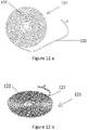
- FIGs 12a - 12d there is shown another embodiment of a balance spring (121) having a main body (122) and an outer portion (123).
- the original balance spring (121) is shown before twisting is shown in Figure 12a , which has a twisting region and one bending region. After the twisting and raising the outer portion (123) away from and then towards the plane of the paper, the outer portion (123) is bent over the main body portion (122) to form the shape of overcoil balance spring.
- balance springs whereby the arrangement of the outer portion with respect to the main body portion may vary, as well as the mode of movement of the outer portion away from and over the main body portion of the balance spring, so as to form an overcoil portion and thus an overcoil balance spring, in addition to the exemplary embodiments sa depicted and described, without departing from the scope of the invention.
- the present invention provides a balance spring having the following advantages:
Landscapes
- Physics & Mathematics (AREA)
- General Physics & Mathematics (AREA)
- Engineering & Computer Science (AREA)
- Manufacturing & Machinery (AREA)
- Springs (AREA)
Description
- The present invention relates to a silicon based overcoil balance spring. In particular, the present invention relates a silicon overcoil spring and the method of manufacturing the same.
- The regulating assembly of a timepiece typically includes a balance wheel which is an inertia flywheel, and a balance spring which is a resonator. These two components determine the working quality and accuracy of a timepiece. The resonant frequency of the balance spring and the balance wheel system control the working and regulation of the timepiece movement.
- The use of silicon as a material for fabrication of a balance spring is known in the art of watch springs. The ultrahigh fabrication precision of such fabrication processes, owing to the progress developed by the IC industry, offers high precision of a balance spring's dimensions. Further, silicon is a non-magnetic material, which provides advantages in timepiece manufacturing.
- It is known that the coils of a plane balance spring deform eccentrically when the balance spring is in operation, which causes the centre of gravity of the balance spring to not correspond to the centre of the rotation of the balance wheel and the balance spring. This alters the setting of the balance wheel and the balance spring, and causes anisochronous motion.
- Although the centre of gravity of the balance spring could be returned arbitrarily to the centre by being shifted, this does not address this disadvantage. As during the working of a balance spring the centre of the gravity would move, this would therefore no longer coincide with the initial centre of gravity.
- Different solutions have been proposed in the prior art to reduce the above disadvantage and to so as to make the deformations of the balance spring coils less non-concentric.
- Examples of such prior art include:
- (i) the Breguet overcoil balance spring with a so-called Philips curve in which an outer curve is lifted into a second plane above the balance spring, and
- (ii) the Straumann double balance springs in which two balance springs manufactured as a matched pair are arranged so that they oscillate against one another, with a view to cancelling or reducing such effects.
- The first example (i) is directed to modifying the initial plane balance springs so that it becomes a balance spring occupying a plurality of planes. Breguet has manufactured a Breguet overcoil balance spring with silicon based material, whereby the balance spring is formed from two or more pieces as an assembled overcoil spring.
- The second example (ii) consists of two balance springs which are manufactured as a matched pair. They are arranged so that they oscillate against one another such that the centres of gravity of the two springs move outwards and inwards on opposing symmetrical paths as they oscillate, with a view having the cumulative centre of gravity of the two springs remain towards the centre of the arbor. As there are two balance springs in this oscillating system, this however results in more energy consumption.
-
CH703272 A2 - The present invention seeks to provide a balance spring which overcomes or minimizes at least some of the deficiencies as exhibited by those of the prior art.
- In a first aspect, the present invention provides a method of producing unitary formed silicon balance spring having an overcoil portion for regulation of a mechanical timepiece, said method including the steps of:
- (i) providing a silicon balance spring having a main body portion, and an outer portion for formation as an overcoil portion, wherein the outer portion extends radially outward from an outermost turn of the main body portion, and wherein said main body portion and said outer portion are integrally formed from a silicon based material and are formed in a co-planar configuration;
- (ii) moving said outer portion in a direction relative to and out of the plane of said main body portion, and in a direction towards over said main body portion and towards the plane of the main body portion; and
- (iii) providing a stress relaxation process to the balance spring so as to relieve internal stresses induced within the balance spring from step (ii);
- The movement of said step (ii) may be effected incrementally in the direction towards over said main body portion and towards the plane of the main body portion. Between or during incremental steps of step (ii), the step (iii) may be effected.
- Preferably an oxidation step of at least the outer portion is effected prior to effecting step (ii), so as to remove or minimize stress concentration defects. Preferably, the oxidation step includes exposure to a hydrogen fluoride solution.
- The method may include the step of twisting the outer portion through at least one 180° turn, wherein said at least one 180° turn is about the longitudinal axis of said outer portion, and where the outer portion is twisted in a region adjacent the outer turn of said main body portion.
- Preferably the stress relaxation process is performed at a temperature of greater than 500°C, more preferably at a temperature of greater than 700°C, and more preferably at a temperature of greater than 1100°C.
- Preferably the stress relaxation process is performed for at least 10 hours, more preferably for at least 20 hours, and more preferably for at least 30 hours. Preferably the balance spring is formed by way of a micro-fabrication technique, more preferably by way of a deep reactive ion etching (DRIE) technique.
- In a second aspect, the present invention provides a silicon based balance spring comprising:
- a main body portion of a having a spring arrangement for providing restoration torque for regulation of a mechanical timepiece, and
- an overcoil portion wherein the overcoil portion extending in direction relative to and out of the plane of said main body portion, and in a direction towards over said main body portion and towards the plane of the main body portion;
- wherein said main body portion and said overcoil portion are unitary formed in accordance with any of the appended claims 1 to 10.
- Preferably the balance spring is formed by way of a micro-fabrication technique, and more preferably by way of a deep reactive ion etching (DRIE) technique.
- Preferred embodiments of the present invention will be explained in further detail below by way of examples and with reference to the accompanying drawings, in which:
-
Figure 1a and Figure 1b depict a perspective and a top view of an embodiment of a balance spring in accordance with the present invention prior to formation of an overcoil arrangement; -
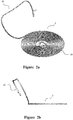
Figure 2a and Figure 2b depict a perspective view and a side view of the embodiment of a balance spring ofFigure 1a and Figure 1b with an overcoil arrangement partly configured; -
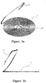
Figure 3a and Figure 3b depict a perspective and a side view of the embodiment of a balance spring ofFigure 2a and Figure 2b with the overcoil arrangement further partly configured; -
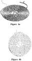
Figure 4a and Figure 4b depict a perspective and a top view of the embodiment of the balance spring ofFigure 1a to Figure 3b with the overcoil arrangement fully configured; -
Figure 5, Figure 6 ,Figure 7, Figure 8 andFigure 9 depict formation of the balance spring ofFigures 1a to 4b ; -
Figure 10 depicts an SEM representation of a cross sectional view of a coil turn of a balance spring in accordance with the present invention; -
Figure 11a depicts a top view of a further embodiment of a balance spring in accordance with the present invention prior to formation of an overcoil arrangement; -
Figure 11b depict a perspective view of the embodiment of a balance spring ofFigure 11a with an overcoil arrangement partly configured; -
Figure 11c and Figure 11d depict a top view and an end view of the embodiment of the balance spring ofFigure 11a to Figure 11b with the overcoil arrangement fully configured; -
Figure 12a depicts a top view of another embodiment of a balance spring in accordance with the present invention prior to formation of an overcoil arrangement; -
Figure 12b depict a perspective view of the embodiment of a balance spring ofFigure 12a with an overcoil arrangement partly configured; and -
Figure 12c and Figure 12d depict a top view and an end view of the embodiment of the balance spring ofFigure 12a to Figure 12b with the overcoil arrangement fully configured. - The present invention provides a planar silicon balance spring having a main body and an integrally formed overcoil portion so as to improve concentricity and isochronicity of such a spring when utilized in a timepiece.
- The balance spring includes an overcoil portion which achieves said improvement in concentricity and isochronicity which is integrally formed with the main body of the balance spring and extends from the periphery of the main body of the balance spring in an out of plane overcoil arrangement, and manufacturing process for the formation thereof.
- The present invention provides a method of manufacturing an overcoil balance spring, whereby the balance spring is formed from a silicon based material, which provides a unitary formed silicon overcoil balance spring, without the necessity of any connection unit, as required by the previously mentioned silicon overcoil balance spring made by
Breguet, US,7950,847 . - In accordance with the present invention, a balance spring is provided and unitary formed from a silicon based material, whereby the balance spring includes a main body portion and overcoil portion.
- The balance spring is initially formed and provided with all portions in a co-planar form, and is formed by micro-manufacturing techniques, including Photo Lithography and Deep reactive-ion etching (DRIE), whereby the main body portion, collet portion and overcoil portion are co-planar.
- Utilising techniques and processes in accordance with the present invention as described below and as described in reference to the accompanying drawings, the overcoil portion is provided out of the plane and in accordance with overcoil portions of balance springs as utilized for increasing balance spring concentricity, whilst not comprising the mechanical integrity of the balance spring and without the necessity for a separate overcoil portion to be adjoined to the main body portion.
- In accordance with the present invention, the shape and configuration of portions of the balance spring may be modified by utilising thermal techniques, without compromising the requisite mechanical properties of the balance spring as required during use in a time piece.
- In the present invention, there is provided a method for producing a unitary formed silicon balance spring having an overcoil portion and a spring resulting therefrom, whereby a balance spring is initially formed having a main body portion for providing restoration torque for regulation of a mechanical timepiece, and an outer portion for formation of an overcoil portion wherein the outer portion extends radially outward from an outermost turn of the main body portion. The main body portion and the outer portion are integrally formed from a silicon based material and are formed in a co-planar configuration.
- The outer portion is moved in a direction relative to said main body portion and out of the plane of said main body portion, and in a direction towards over said main body portion and towards the plane of the main body portion.
- A stress relaxation process is provided to the balance spring so as to relieve internal stresses induced within the balance spring, and upon movement of said outer portion into the plane of said main body portion, the outer portion is located in an overcoil configuration relative to said main body portion.
- Embodiments and examples of the present invention are described as follows.
- Referring to the embodiment as depicted in
Figure 1a - Figure 4b , as shown inFigure 1a and Figure 1b a balance spring (2) having a main body portion (23) and an outer portion (22) prior to formation of an overcoil portion by a twisting movement is shown, and which has a "C" shape twisting region (21), whereby balance spring (2) is provided in an initial planar configuration and the outer portion (23) and main body portion (23) are integrally formed from a single material and are co-planar. The radius of the twisting region R1 is slightly less than that of the second most outer coil R2. This design helps the twisting region (21) of final overcoil balance spring to follow the spiral of Archimedes, as seen from the top view. - As shown in
Figure 2a, Figure 2b ,Figure 3a, Figure 3b ,Figure 4a and Figure 4b there is shown the shape change of the balance spring (2) to form an overcoil portion, whereby the shape change which is effected to form the overcoil portion by moving said outer portion (22) in a direction relative to and out of the plane of said main body portion (23), and in a direction towards over the main body portion (23) and towards the plane of the main body portion (23), causing twisting the outer portion (22) away from the plane of said main body portion (23) step by step. - The shape of the original balance spring (2) as depicted transforms to an overcoil balance spring after the outer portion (22) being moved towards the plane of the body of the spring as depicted in
Figure 4a and Figure 4b , whereby the outer portion (22) has formed an the overcoil portion by being been twisted 180° with respect to the adjacent the outermost turn of the main body of the spring. - Other geometries of balance springs in accordance with the present invention are discussed below in relation to other embodiments.
- Referring to
Figures 5 to 9 , there is depicted the manner in which the balance spring ofFigs 1a - 4b may be manipulated in accordance with the present invention, so as to provide a unitary formed overcoil balance spring. - To achieve the movement and twisting process of the balance spring (2), it is necessary to utilize holders (61, 62) to grip the main body portion (23) and the outer portion (22). In the present embodiment, the outer portion (22) of the balance spring (2) needs to be flipped 180°, and this process requires high positioning accuracy.
- For this embodiment design, there are provided two holders needed for maintaining the positional accuracy, as shown in
Figures 5 to 9 . The first holder (61) is for holding all the centre coils of the main body portion (23) of the balance spring (2) except for the outer portion (22) including the outer portion as a "C" shape twisting region (21), and the second holder (62) is for holding the outer portion (22) of the balance spring (2). - In the present embodiment, both of holders (61, 62) are formed from silicon by DRIE, and are oxidized by thermal oxidation. The first holder (61) for holding the centre coils of the main body portion (23) of the balance spring (2) is made with a series of trenches that are almost identical to the coils of the main body portion (23) of the balance spring (2). The trench is provided with a width that is slightly larger than the line width of the balance spring coil. This assists the balance spring centre coils of the main body portion (23) to maintain their original shape when torque is applied on the twisting region (21).
- The second holder (62) for holding the outer portion (22) is also provided with a trench sized so as to accommodate the coil outer portion. The same treatment as the first holder (61) applies on the second holder (62).
- During the movement process, all the turns except for the twisting region (21) need to be fixed by holders. The centre coils of the main body portion (23) and the outer portion (22) of the balance spring (2) are fitted into the first holder (61), and the second holder (62) respectively, as shown in
Figure 6 , then the balance spring is moved as described in accordance with the present invention. -
Figures 6 ,7 ,8 and9 progressively depict the movement process of formation of the overcall portion. After the balance spring is moved into the overcoil shape as shown inFigure 9 , it is transferred into the annealing furnace together with the holders. - To achieve an overcoil balance spring with low internal stress, high temperature and long duration annealing is preferred. If the samples are put in a furnace without N2 or Ar protection, the temperature should be lower than the oxidation temperature of silicon to avoid adhesion of the balance spring to the holders, and a temperature of 800°C is applicable for this application. After cooling, the original balance spring (2) is provided as an overcoil balance spring.
- For different balance spring dimensions and sizes, there may be some cases when the twisting region (21) of the balance spring (2) cannot afford a large twisting angle. In such cases, the annealing process may be provided in incremental steps with movement of the outer portion of the balance spring being in several steps.
- After locating the balance spring (2) into the two holders (61, 62), as shown in
Figure 6 , the balance spring outer portion (22) is twisted for 60°, as shown inFigure 7 , and then is annealed utilizing annealing conditions discussed below. - After the first annealing, the balance spring (2) changes into a twisted formation, as shown in
Figure 2 . A second twisting for another 60° is then applied on the twisted balance spring (2), as shown inFigure 7 , and is annealed subsequently. - This annealing process results in a further twisted balance spring (2), as shown in
Figure 2 , The final twisting for the rest 60° is performed on the twisted balance spring (2) after the previous two annealing processes, as shown inFigure 8 . - Then the balance spring (2) and the holders (61, 62) are transferred into the furnace for the finale annealing. After removing the holders (61, 62), the silicon balance spring (2) transforms into overcoil balance spring permanently.
- Silicon is a brittle material at room temperature, however at temperatures between 520°C to 600°C the transition from brittle to ductile behaviour is obeyed. At temperatures higher than 700°C, it has been found that a requisite amount of plastic deformation is possible.
- Whilst the present embodiment describes incremental movement of the outer portion over the main body portion, this may be continuous movement in other embodiments, which may include incremental or continuous heat treatment.
- In accordance with the present invention and in reference to the above embodiments and equally as applicable to other or alternate embodiments such as those as described with reference to
Figures 11a - 12d below, a silicon balance spring is prepared prior to the oxidation process of the DRIE (deep reactive ion etching) etched silicon balance spring (2), the outer portion of the balance spring is twisted to another plane, and fixed by using a quartz fixture. - The oxidation temperature is preferably about 1100°C, and the temperature is kept fixed for approximately 30 hours. After the oxidation process it has been demonstrated that the shape of the outer portion of the balance spring is altered to the pre-set shape by the quartz fixture.
- In order to confirm that the shape change is not due to the oxide layer, the balance spring was immersed in a Hydrogen Fluoride (HF) solution. When the oxide layer was removed from the balance spring surface, the shape of the balance spring remained the same as when oxidized.
- Accordingly, it may be demonstrated that the crystal structure changes during the oxidation process, which results in the permanent shape change.
- In reference to stresses induced during the movement and twisting of the outer portion of the balance spring, the following calculations are demonstrative of the mechanics and stresses.
- To simplify the calculation on twisting angle and shear stress, the outer portion of the balance spring to be twisted is to be regarded as a straight beam, with beam width of t and h, and beam length l.
- The twisting angle Φ is a function of the shear modulus , the polar moment inertia Ip applied torque on the beam Mt , and the beam length l. We have :

- The max shear stress in the beam during the twisting is τ = 3Mt /h · t
2 . - The relationship between Φ and τ can then be found, τ = 3Φ·G·Ip / l·h·t
2 . - For a beam with rectangular cross section, the polar moment inertia is Ip = K · h · t 3, where K is a constant related to the ratio of h/t.
- We have τ = 3K·Φ·G·t / l , take the example of h = 2.5t = 100µm, l = 5mm, G = 69GPa, we have K = 0.249.
- Thus, for the given parameter of the beam, the max stress is τ = 400Φ (MPa).
- For a twisting angle of 180°, the maximum stress inside the balance spring coil is about 1.3GPa. According to Pearson at al. (
Volume 5, Issue 4, April 1957, Pages 181-191), the fracture stress for thin silicon rods in room temperature is about 3GPa. - Further, the silicon torsional scanning mirror made by IBM (IBM J.RES. DEVELOP. VOL.24, NO.5 SEPTEMBER 1980, Pages 631-637) also proves that thin silicon rods can afford large fracture stress, as were made and tested by researchers, and found that this value is so the balance spring is strong enough to afford a twist of 180°.
- Preferably, prior to effecting movement/twisting of the outer portion of the balance spring, an oxidation treatment is utilized.
- During the oxidation, oxygen atoms penetrate the previously formed oxide layer to react with the silicon atoms so as to form silicon oxide. At sharp corners of the balance spring, the penetration occurs more easily due to the relatively larger surface area, and thus results in thicker oxide layer, which makes the interface of silicon and silicon oxide to be smooth.
- When dipped into HF solution, the initial sharp corners of the silicon balance spring are removed with the oxide layer, as can be seen in the SEM image of the cross section of the oxidized silicon balance spring in
Figure 10 . - As can be seen where (11) is the silicon core, (12) is the oxide layer, the sidewall roughness has been greatly reduced, and the corner of the cross section has been rounded.
- The oxidation process performed before the large angle twisting can remove the defects resulted from the DRIE process, as well as the sharp corners of the cross section, which makes the balance spring more durable due to reduction in stress concentrations.
- Referring to
Figures 11a - 11d there is shown and described a further embodiment of the present invention, and with reference toFigures 12a - 12d there is shown and described another embodiment of the present invention. -
Figures 11a - 11d show a further embodiment of a balance spring (111) having a main body portion (112) and an outer portion (113). This embodiment is similar to that ofFigures 1a - 4b above, however with an opposite twisting direction of theouter portion 113. As for the embodiment ofFigures 1a - 4b with the "C" shape 180° twisting region, the outer portion (113) is twisted away from the plane of the main body portion (112) and out of the paper. However, by contrast, for the present embodiment, the "S" shape 180° twisting region, the outer portion (113) is twisted towards and into the paper. - As shown in
Figures 12a - 12d , there is shown another embodiment of a balance spring (121) having a main body (122) and an outer portion (123). The original balance spring (121) is shown before twisting is shown inFigure 12a , which has a twisting region and one bending region. After the twisting and raising the outer portion (123) away from and then towards the plane of the paper, the outer portion (123) is bent over the main body portion (122) to form the shape of overcoil balance spring. - As will be appreciated by those skilled in the art, there exist other and alternate embodiments of balance springs, whereby the arrangement of the outer portion with respect to the main body portion may vary, as well as the mode of movement of the outer portion away from and over the main body portion of the balance spring, so as to form an overcoil portion and thus an overcoil balance spring, in addition to the exemplary embodiments sa depicted and described, without departing from the scope of the invention. The present invention provides a balance spring having the following advantages:
- (i) precision manufacturing;
- (ii) mass concentricity compensation
- (iii) unitary construct and no additional portions required to be affixed to the spring
- (iv) possible for constant cross-section area due to absence of joining members, thus:
- a. constant second moment of area thus more uniform stiffness,
- b. constant cross sectional area thus ease of thermal compensation oxide by layer utilization.
Claims (13)
- A method of producing a unitary formed silicon balance spring (2) having an overcoil portion for regulation of a mechanical timepiece, said method including the steps of:(i) providing a silicon balance spring having a main body portion (23), and an outer portion (22) for formation as an overcoil portion, wherein the outer portion extends radially outward from an outermost turn of the main body portion, and wherein said main body portion and said outer portion are integrally formed from a silicon based material and are formed in a co-planar configuration;(ii) moving said outer portion (22) in a direction relative to and out of the plane of said main body portion (23), and in a direction towards over said main body portion and towards the plane of the main body portion; and(iii) providing a stress relaxation process to the balance spring so as to relieve internal stresses induced within the balance spring from step (ii);wherein upon movement of said outer portion (22) into the plane of said main body portion (23), the outer portion is located in an overcoil configuration relative to said main body portion.
- A method according to claim 1, wherein the movement of said step (ii) is effected incrementally in the direction towards over said main body portion (23) and towards the plane of the main body portion.
- A method according to claim 2, wherein between or during incremental steps of step (ii), the step (iii) is effected.
- A method according to any one of the preceding claims, wherein an oxidation step of at least the outer portion is effected prior to effecting step (ii), so as to remove or minimize stress concentration defects.
- A method according to claim 4, wherein said oxidation step includes exposure to a hydrogen fluoride solution.
- A method according to any one of the preceding claims, further including the step of twisting the outer portion (22) through at least one 180° turn, wherein said at least one 180° turn is about the longitudinal axis of said outer portion, and where the outer portion is twisted in a region adjacent the outer turn of said main body portion (23).
- A method according to any one of the preceding claims, wherein said stress relaxation process is performed at a temperature of greater than 500°C, more preferably at a temperature of greater than 700°C, and more preferably at a temperature of greater than 1100°C.
- A method according to any one of the preceding claims, wherein said stress relaxation process is performed for at least 10 hours, more preferably for at least 20 hours, and more preferably for at least 30 hours.
- A method according to any one of the preceding claims, wherein said balance spring (2) is formed by way of a micro-fabrication technique.
- A method according to any one of the preceding claims, wherein said balance spring (2) is formed by way of a deep reactive ion etching (DRIE) technique.
- A silicon based balance spring (2) comprising:a main body portion (23) of a having a spring arrangement for providing restoration torque for regulation of a mechanical timepiece, andan overcoil portion (22) wherein said main body portion and said overcoil portion are unitary formed in accordance with any of claims 1 to 10.
- A silicon based balance spring (2) according to claim 11, wherein said balance spring is formed by way of a micro-fabrication technique.
- A silicon based balance spring according to claim 11 or claim 12 wherein said balance spring is formed by way of a deep reactive ion etching (DRIE) technique.
Applications Claiming Priority (1)
| Application Number | Priority Date | Filing Date | Title |
|---|---|---|---|
| HK13108857.0A HK1193537A2 (en) | 2013-07-29 | 2013-07-29 | Silicon overcoil balance spring |
Publications (3)
| Publication Number | Publication Date |
|---|---|
| EP2833221A2 EP2833221A2 (en) | 2015-02-04 |
| EP2833221A3 EP2833221A3 (en) | 2015-09-02 |
| EP2833221B1 true EP2833221B1 (en) | 2017-05-24 |
Family
ID=51539448
Family Applications (1)
| Application Number | Title | Priority Date | Filing Date |
|---|---|---|---|
| EP14178831.5A Active EP2833221B1 (en) | 2013-07-29 | 2014-07-28 | Silicon overcoil balance spring |
Country Status (4)
| Country | Link |
|---|---|
| US (1) | US9411312B2 (en) |
| EP (1) | EP2833221B1 (en) |
| CN (1) | CN104345628B (en) |
| HK (1) | HK1193537A2 (en) |
Families Citing this family (3)
| Publication number | Priority date | Publication date | Assignee | Title |
|---|---|---|---|---|
| HK1209578A2 (en) | 2015-02-17 | 2016-04-01 | Master Dynamic Limited | Silicon hairspring |
| EP3309625B1 (en) * | 2016-10-13 | 2020-07-29 | Nivarox-FAR S.A. | Hairspring intended for being attached by a spring washer |
| EP3680731B1 (en) * | 2019-01-08 | 2022-06-08 | Patek Philippe SA Genève | Method for manufacturing clock components made of fragile material |
Family Cites Families (11)
| Publication number | Priority date | Publication date | Assignee | Title |
|---|---|---|---|---|
| US570394A (en) * | 1896-10-27 | Hair-spring for watches | ||
| US469914A (en) * | 1892-03-01 | Watch balance-spring | ||
| US3958410A (en) * | 1975-06-02 | 1976-05-25 | Timex Corporation | Termination device from hairspring-hub to drive coil on two conductor hairspring |
| EP1445670A1 (en) * | 2003-02-06 | 2004-08-11 | ETA SA Manufacture Horlogère Suisse | Balance-spring resonator spiral and its method of fabrication |
| ATE466315T1 (en) * | 2004-07-02 | 2010-05-15 | Nivarox Sa | CIRCULAR SPRING WITH MODIFIED OUTER CURVE |
| EP1791039A1 (en) * | 2005-11-25 | 2007-05-30 | The Swatch Group Research and Development Ltd. | Hairspring made from athermic glass for a timepiece movement and its method of manufacture |
| EP2105807B1 (en) * | 2008-03-28 | 2015-12-02 | Montres Breguet SA | Monobloc elevated curve spiral and method for manufacturing same |
| EP2184653A1 (en) * | 2008-11-06 | 2010-05-12 | Montres Breguet S.A. | Spiral with terminal curve elevation in micro-machinable material |
| EP2233989A1 (en) * | 2009-03-24 | 2010-09-29 | Manufacture et fabrique de montres et chronomètres Ulysse Nardin Le Locle SA | Hairspring and its index-assembly |
| CH703272B1 (en) | 2010-06-10 | 2015-02-13 | Montres Breguet Sa | Breguet terminal curve to locally thickened. |
| CH703337B1 (en) | 2010-06-21 | 2015-06-15 | Montres Breguet Sa | A method of manufacturing a spring assembly of timepiece micro-machinable material. |
-
2013
- 2013-07-29 HK HK13108857.0A patent/HK1193537A2/en not_active IP Right Cessation
-
2014
- 2014-07-28 EP EP14178831.5A patent/EP2833221B1/en active Active
- 2014-07-28 US US14/444,918 patent/US9411312B2/en active Active
- 2014-07-29 CN CN201410366303.5A patent/CN104345628B/en active Active
Also Published As
| Publication number | Publication date |
|---|---|
| US9411312B2 (en) | 2016-08-09 |
| EP2833221A2 (en) | 2015-02-04 |
| US20150029828A1 (en) | 2015-01-29 |
| HK1193537A2 (en) | 2014-09-19 |
| EP2833221A3 (en) | 2015-09-02 |
| CN104345628B (en) | 2017-10-27 |
| HK1205285A1 (en) | 2015-12-11 |
| CN104345628A (en) | 2015-02-11 |
| HK1205286A1 (en) | 2015-12-11 |
Similar Documents
| Publication | Publication Date | Title |
|---|---|---|
| EP3056948B1 (en) | Silicon hairspring | |
| CN100360828C (en) | Clock balance spring and manufacturing method thereof | |
| EP3422116B1 (en) | Timepiece hairspring | |
| JP5474432B2 (en) | Hairspring for ten wheel / hairspring vibrator | |
| US9104178B2 (en) | Method for making a spring for a timepiece | |
| JP4805560B2 (en) | Spring balance resonator adjusted for temperature change | |
| CN101361027B (en) | Spiral hairspring for watch mechanism movement made of heat-insulating glass and manufacturing method thereof | |
| US9411312B2 (en) | Silicon overcoil balance spring | |
| EP2264553B1 (en) | Thermocompensated spring and manufacturing method thereof | |
| CN106597828B (en) | Hairspring made of heavily doped silicon for a timepiece | |
| US20170285573A1 (en) | Crystalline Compounds for Use in Mechanical Watches and Methods of Manufacture Thereof | |
| US20190271946A1 (en) | Process for producing a thermo-compensated oscillator | |
| US20230126149A1 (en) | Method for manufacturing a silicon-based timepiece component | |
| CN112049843B (en) | Method for producing a connecting element and connecting element | |
| HK1205285B (en) | Silicon overcoil balance spring | |
| CN108196438A (en) | The axis of going barrel, clockwork spring and going barrel, watch and clock movement, watch and table including the axis and clockwork spring | |
| HK1205286B (en) | Silicon overcoil balance spring | |
| EP3422115B1 (en) | Timepiece spiral spring | |
| JP3222608U (en) | Angle return spring for heat-compensated vibrator | |
| TWI910910B (en) | Method for manufacturing horological balance springs | |
| JP6754866B2 (en) | Main spring | |
| JP2020106526A (en) | Strengthened timepiece component | |
| JP2013152447A (en) | Manufacturing method of torsion bar, vibration element, optical scanner, and image forming apparatus and image projection device using the same |
Legal Events
| Date | Code | Title | Description |
|---|---|---|---|
| 17P | Request for examination filed |
Effective date: 20140728 |
|
| AK | Designated contracting states |
Kind code of ref document: A2 Designated state(s): AL AT BE BG CH CY CZ DE DK EE ES FI FR GB GR HR HU IE IS IT LI LT LU LV MC MK MT NL NO PL PT RO RS SE SI SK SM TR |
|
| AX | Request for extension of the european patent |
Extension state: BA ME |
|
| PUAI | Public reference made under article 153(3) epc to a published international application that has entered the european phase |
Free format text: ORIGINAL CODE: 0009012 |
|
| PUAL | Search report despatched |
Free format text: ORIGINAL CODE: 0009013 |
|
| AK | Designated contracting states |
Kind code of ref document: A3 Designated state(s): AL AT BE BG CH CY CZ DE DK EE ES FI FR GB GR HR HU IE IS IT LI LT LU LV MC MK MT NL NO PL PT RO RS SE SI SK SM TR |
|
| AX | Request for extension of the european patent |
Extension state: BA ME |
|
| RIC1 | Information provided on ipc code assigned before grant |
Ipc: G04D 3/00 20060101ALI20150727BHEP Ipc: G04B 17/06 20060101AFI20150727BHEP |
|
| REG | Reference to a national code |
Ref country code: HK Ref legal event code: DE Ref document number: 1205285 Country of ref document: HK |
|
| R17P | Request for examination filed (corrected) |
Effective date: 20160302 |
|
| RBV | Designated contracting states (corrected) |
Designated state(s): AL AT BE BG CH CY CZ DE DK EE ES FI FR GB GR HR HU IE IS IT LI LT LU LV MC MK MT NL NO PL PT RO RS SE SI SK SM TR |
|
| 17Q | First examination report despatched |
Effective date: 20160425 |
|
| GRAP | Despatch of communication of intention to grant a patent |
Free format text: ORIGINAL CODE: EPIDOSNIGR1 |
|
| INTG | Intention to grant announced |
Effective date: 20161223 |
|
| GRAS | Grant fee paid |
Free format text: ORIGINAL CODE: EPIDOSNIGR3 |
|
| GRAA | (expected) grant |
Free format text: ORIGINAL CODE: 0009210 |
|
| AK | Designated contracting states |
Kind code of ref document: B1 Designated state(s): AL AT BE BG CH CY CZ DE DK EE ES FI FR GB GR HR HU IE IS IT LI LT LU LV MC MK MT NL NO PL PT RO RS SE SI SK SM TR |
|
| REG | Reference to a national code |
Ref country code: GB Ref legal event code: FG4D |
|
| REG | Reference to a national code |
Ref country code: CH Ref legal event code: EP |
|
| REG | Reference to a national code |
Ref country code: IE Ref legal event code: FG4D |
|
| REG | Reference to a national code |
Ref country code: AT Ref legal event code: REF Ref document number: 896311 Country of ref document: AT Kind code of ref document: T Effective date: 20170615 |
|
| REG | Reference to a national code |
Ref country code: DE Ref legal event code: R096 Ref document number: 602014010067 Country of ref document: DE |
|
| REG | Reference to a national code |
Ref country code: FR Ref legal event code: PLFP Year of fee payment: 4 |
|
| REG | Reference to a national code |
Ref country code: CH Ref legal event code: NV Representative=s name: FIAMMENGHI-FIAMMENGHI, CH |
|
| REG | Reference to a national code |
Ref country code: NL Ref legal event code: MP Effective date: 20170524 |
|
| REG | Reference to a national code |
Ref country code: LT Ref legal event code: MG4D |
|
| REG | Reference to a national code |
Ref country code: AT Ref legal event code: MK05 Ref document number: 896311 Country of ref document: AT Kind code of ref document: T Effective date: 20170524 |
|
| PG25 | Lapsed in a contracting state [announced via postgrant information from national office to epo] |
Ref country code: AT Free format text: LAPSE BECAUSE OF FAILURE TO SUBMIT A TRANSLATION OF THE DESCRIPTION OR TO PAY THE FEE WITHIN THE PRESCRIBED TIME-LIMIT Effective date: 20170524 Ref country code: NO Free format text: LAPSE BECAUSE OF FAILURE TO SUBMIT A TRANSLATION OF THE DESCRIPTION OR TO PAY THE FEE WITHIN THE PRESCRIBED TIME-LIMIT Effective date: 20170824 Ref country code: HR Free format text: LAPSE BECAUSE OF FAILURE TO SUBMIT A TRANSLATION OF THE DESCRIPTION OR TO PAY THE FEE WITHIN THE PRESCRIBED TIME-LIMIT Effective date: 20170524 Ref country code: LT Free format text: LAPSE BECAUSE OF FAILURE TO SUBMIT A TRANSLATION OF THE DESCRIPTION OR TO PAY THE FEE WITHIN THE PRESCRIBED TIME-LIMIT Effective date: 20170524 Ref country code: FI Free format text: LAPSE BECAUSE OF FAILURE TO SUBMIT A TRANSLATION OF THE DESCRIPTION OR TO PAY THE FEE WITHIN THE PRESCRIBED TIME-LIMIT Effective date: 20170524 Ref country code: ES Free format text: LAPSE BECAUSE OF FAILURE TO SUBMIT A TRANSLATION OF THE DESCRIPTION OR TO PAY THE FEE WITHIN THE PRESCRIBED TIME-LIMIT Effective date: 20170524 Ref country code: GR Free format text: LAPSE BECAUSE OF FAILURE TO SUBMIT A TRANSLATION OF THE DESCRIPTION OR TO PAY THE FEE WITHIN THE PRESCRIBED TIME-LIMIT Effective date: 20170825 |
|
| PG25 | Lapsed in a contracting state [announced via postgrant information from national office to epo] |
Ref country code: BG Free format text: LAPSE BECAUSE OF FAILURE TO SUBMIT A TRANSLATION OF THE DESCRIPTION OR TO PAY THE FEE WITHIN THE PRESCRIBED TIME-LIMIT Effective date: 20170824 Ref country code: SE Free format text: LAPSE BECAUSE OF FAILURE TO SUBMIT A TRANSLATION OF THE DESCRIPTION OR TO PAY THE FEE WITHIN THE PRESCRIBED TIME-LIMIT Effective date: 20170524 Ref country code: IS Free format text: LAPSE BECAUSE OF FAILURE TO SUBMIT A TRANSLATION OF THE DESCRIPTION OR TO PAY THE FEE WITHIN THE PRESCRIBED TIME-LIMIT Effective date: 20170924 Ref country code: NL Free format text: LAPSE BECAUSE OF FAILURE TO SUBMIT A TRANSLATION OF THE DESCRIPTION OR TO PAY THE FEE WITHIN THE PRESCRIBED TIME-LIMIT Effective date: 20170524 Ref country code: RS Free format text: LAPSE BECAUSE OF FAILURE TO SUBMIT A TRANSLATION OF THE DESCRIPTION OR TO PAY THE FEE WITHIN THE PRESCRIBED TIME-LIMIT Effective date: 20170524 Ref country code: LV Free format text: LAPSE BECAUSE OF FAILURE TO SUBMIT A TRANSLATION OF THE DESCRIPTION OR TO PAY THE FEE WITHIN THE PRESCRIBED TIME-LIMIT Effective date: 20170524 |
|
| PG25 | Lapsed in a contracting state [announced via postgrant information from national office to epo] |
Ref country code: CZ Free format text: LAPSE BECAUSE OF FAILURE TO SUBMIT A TRANSLATION OF THE DESCRIPTION OR TO PAY THE FEE WITHIN THE PRESCRIBED TIME-LIMIT Effective date: 20170524 Ref country code: EE Free format text: LAPSE BECAUSE OF FAILURE TO SUBMIT A TRANSLATION OF THE DESCRIPTION OR TO PAY THE FEE WITHIN THE PRESCRIBED TIME-LIMIT Effective date: 20170524 Ref country code: DK Free format text: LAPSE BECAUSE OF FAILURE TO SUBMIT A TRANSLATION OF THE DESCRIPTION OR TO PAY THE FEE WITHIN THE PRESCRIBED TIME-LIMIT Effective date: 20170524 Ref country code: SK Free format text: LAPSE BECAUSE OF FAILURE TO SUBMIT A TRANSLATION OF THE DESCRIPTION OR TO PAY THE FEE WITHIN THE PRESCRIBED TIME-LIMIT Effective date: 20170524 Ref country code: RO Free format text: LAPSE BECAUSE OF FAILURE TO SUBMIT A TRANSLATION OF THE DESCRIPTION OR TO PAY THE FEE WITHIN THE PRESCRIBED TIME-LIMIT Effective date: 20170524 |
|
| REG | Reference to a national code |
Ref country code: DE Ref legal event code: R097 Ref document number: 602014010067 Country of ref document: DE |
|
| PG25 | Lapsed in a contracting state [announced via postgrant information from national office to epo] |
Ref country code: PL Free format text: LAPSE BECAUSE OF FAILURE TO SUBMIT A TRANSLATION OF THE DESCRIPTION OR TO PAY THE FEE WITHIN THE PRESCRIBED TIME-LIMIT Effective date: 20170524 Ref country code: SM Free format text: LAPSE BECAUSE OF FAILURE TO SUBMIT A TRANSLATION OF THE DESCRIPTION OR TO PAY THE FEE WITHIN THE PRESCRIBED TIME-LIMIT Effective date: 20170524 Ref country code: IT Free format text: LAPSE BECAUSE OF FAILURE TO SUBMIT A TRANSLATION OF THE DESCRIPTION OR TO PAY THE FEE WITHIN THE PRESCRIBED TIME-LIMIT Effective date: 20170524 |
|
| PLBE | No opposition filed within time limit |
Free format text: ORIGINAL CODE: 0009261 |
|
| STAA | Information on the status of an ep patent application or granted ep patent |
Free format text: STATUS: NO OPPOSITION FILED WITHIN TIME LIMIT |
|
| REG | Reference to a national code |
Ref country code: IE Ref legal event code: MM4A |
|
| PG25 | Lapsed in a contracting state [announced via postgrant information from national office to epo] |
Ref country code: IE Free format text: LAPSE BECAUSE OF NON-PAYMENT OF DUE FEES Effective date: 20170728 |
|
| 26N | No opposition filed |
Effective date: 20180227 |
|
| REG | Reference to a national code |
Ref country code: HK Ref legal event code: GR Ref document number: 1205285 Country of ref document: HK |
|
| PG25 | Lapsed in a contracting state [announced via postgrant information from national office to epo] |
Ref country code: SI Free format text: LAPSE BECAUSE OF FAILURE TO SUBMIT A TRANSLATION OF THE DESCRIPTION OR TO PAY THE FEE WITHIN THE PRESCRIBED TIME-LIMIT Effective date: 20170524 |
|
| REG | Reference to a national code |
Ref country code: BE Ref legal event code: MM Effective date: 20170731 |
|
| PG25 | Lapsed in a contracting state [announced via postgrant information from national office to epo] |
Ref country code: LU Free format text: LAPSE BECAUSE OF NON-PAYMENT OF DUE FEES Effective date: 20170728 |
|
| REG | Reference to a national code |
Ref country code: FR Ref legal event code: PLFP Year of fee payment: 5 |
|
| PG25 | Lapsed in a contracting state [announced via postgrant information from national office to epo] |
Ref country code: BE Free format text: LAPSE BECAUSE OF NON-PAYMENT OF DUE FEES Effective date: 20170731 |
|
| PG25 | Lapsed in a contracting state [announced via postgrant information from national office to epo] |
Ref country code: MT Free format text: LAPSE BECAUSE OF NON-PAYMENT OF DUE FEES Effective date: 20170728 |
|
| PG25 | Lapsed in a contracting state [announced via postgrant information from national office to epo] |
Ref country code: HU Free format text: LAPSE BECAUSE OF FAILURE TO SUBMIT A TRANSLATION OF THE DESCRIPTION OR TO PAY THE FEE WITHIN THE PRESCRIBED TIME-LIMIT; INVALID AB INITIO Effective date: 20140728 Ref country code: MC Free format text: LAPSE BECAUSE OF FAILURE TO SUBMIT A TRANSLATION OF THE DESCRIPTION OR TO PAY THE FEE WITHIN THE PRESCRIBED TIME-LIMIT Effective date: 20170524 |
|
| PG25 | Lapsed in a contracting state [announced via postgrant information from national office to epo] |
Ref country code: CY Free format text: LAPSE BECAUSE OF FAILURE TO SUBMIT A TRANSLATION OF THE DESCRIPTION OR TO PAY THE FEE WITHIN THE PRESCRIBED TIME-LIMIT Effective date: 20170524 |
|
| PG25 | Lapsed in a contracting state [announced via postgrant information from national office to epo] |
Ref country code: MK Free format text: LAPSE BECAUSE OF FAILURE TO SUBMIT A TRANSLATION OF THE DESCRIPTION OR TO PAY THE FEE WITHIN THE PRESCRIBED TIME-LIMIT Effective date: 20170524 |
|
| PG25 | Lapsed in a contracting state [announced via postgrant information from national office to epo] |
Ref country code: TR Free format text: LAPSE BECAUSE OF FAILURE TO SUBMIT A TRANSLATION OF THE DESCRIPTION OR TO PAY THE FEE WITHIN THE PRESCRIBED TIME-LIMIT Effective date: 20170524 |
|
| PG25 | Lapsed in a contracting state [announced via postgrant information from national office to epo] |
Ref country code: PT Free format text: LAPSE BECAUSE OF FAILURE TO SUBMIT A TRANSLATION OF THE DESCRIPTION OR TO PAY THE FEE WITHIN THE PRESCRIBED TIME-LIMIT Effective date: 20170524 |
|
| PG25 | Lapsed in a contracting state [announced via postgrant information from national office to epo] |
Ref country code: AL Free format text: LAPSE BECAUSE OF FAILURE TO SUBMIT A TRANSLATION OF THE DESCRIPTION OR TO PAY THE FEE WITHIN THE PRESCRIBED TIME-LIMIT Effective date: 20170524 |
|
| REG | Reference to a national code |
Ref country code: DE Ref legal event code: R082 Ref document number: 602014010067 Country of ref document: DE Representative=s name: KILBURN & STRODE LLP, NL |
|
| P01 | Opt-out of the competence of the unified patent court (upc) registered |
Effective date: 20230529 |
|
| PGFP | Annual fee paid to national office [announced via postgrant information from national office to epo] |
Ref country code: GB Payment date: 20250619 Year of fee payment: 12 |
|
| PGFP | Annual fee paid to national office [announced via postgrant information from national office to epo] |
Ref country code: FR Payment date: 20250620 Year of fee payment: 12 |
|
| PGFP | Annual fee paid to national office [announced via postgrant information from national office to epo] |
Ref country code: DE Payment date: 20250620 Year of fee payment: 12 |
|
| PGFP | Annual fee paid to national office [announced via postgrant information from national office to epo] |
Ref country code: CH Payment date: 20250801 Year of fee payment: 12 |