EP2833189B1 - Fixture for endoscopic inspection - Google Patents
Fixture for endoscopic inspection Download PDFInfo
- Publication number
- EP2833189B1 EP2833189B1 EP14178326.6A EP14178326A EP2833189B1 EP 2833189 B1 EP2833189 B1 EP 2833189B1 EP 14178326 A EP14178326 A EP 14178326A EP 2833189 B1 EP2833189 B1 EP 2833189B1
- Authority
- EP
- European Patent Office
- Prior art keywords
- fixture
- access port
- endoscopic inspection
- engine
- endoscope
- Prior art date
- Legal status (The legal status is an assumption and is not a legal conclusion. Google has not performed a legal analysis and makes no representation as to the accuracy of the status listed.)
- Active
Links
Images


Classifications
-
- G—PHYSICS
- G01—MEASURING; TESTING
- G01M—TESTING STATIC OR DYNAMIC BALANCE OF MACHINES OR STRUCTURES; TESTING OF STRUCTURES OR APPARATUS, NOT OTHERWISE PROVIDED FOR
- G01M15/00—Testing of engines
- G01M15/02—Details or accessories of testing apparatus
-
- F—MECHANICAL ENGINEERING; LIGHTING; HEATING; WEAPONS; BLASTING
- F01—MACHINES OR ENGINES IN GENERAL; ENGINE PLANTS IN GENERAL; STEAM ENGINES
- F01D—NON-POSITIVE DISPLACEMENT MACHINES OR ENGINES, e.g. STEAM TURBINES
- F01D17/00—Regulating or controlling by varying flow
- F01D17/02—Arrangement of sensing elements
-
- F—MECHANICAL ENGINEERING; LIGHTING; HEATING; WEAPONS; BLASTING
- F01—MACHINES OR ENGINES IN GENERAL; ENGINE PLANTS IN GENERAL; STEAM ENGINES
- F01D—NON-POSITIVE DISPLACEMENT MACHINES OR ENGINES, e.g. STEAM TURBINES
- F01D21/00—Shutting-down of machines or engines, e.g. in emergency; Regulating, controlling, or safety means not otherwise provided for
- F01D21/003—Arrangements for testing or measuring
-
- F—MECHANICAL ENGINEERING; LIGHTING; HEATING; WEAPONS; BLASTING
- F01—MACHINES OR ENGINES IN GENERAL; ENGINE PLANTS IN GENERAL; STEAM ENGINES
- F01D—NON-POSITIVE DISPLACEMENT MACHINES OR ENGINES, e.g. STEAM TURBINES
- F01D25/00—Component parts, details, or accessories, not provided for in, or of interest apart from, other groups
- F01D25/28—Supporting or mounting arrangements, e.g. for turbine casing
- F01D25/285—Temporary support structures, e.g. for testing, assembling, installing, repairing; Assembly methods using such structures
-
- G—PHYSICS
- G01—MEASURING; TESTING
- G01N—INVESTIGATING OR ANALYSING MATERIALS BY DETERMINING THEIR CHEMICAL OR PHYSICAL PROPERTIES
- G01N21/00—Investigating or analysing materials by the use of optical means, i.e. using sub-millimetre waves, infrared, visible or ultraviolet light
- G01N21/84—Systems specially adapted for particular applications
- G01N21/88—Investigating the presence of flaws or contamination
- G01N21/95—Investigating the presence of flaws or contamination characterised by the material or shape of the object to be examined
- G01N21/954—Inspecting the inner surface of hollow bodies, e.g. bores
-
- G—PHYSICS
- G02—OPTICS
- G02B—OPTICAL ELEMENTS, SYSTEMS OR APPARATUS
- G02B23/00—Telescopes, e.g. binoculars; Periscopes; Instruments for viewing the inside of hollow bodies; Viewfinders; Optical aiming or sighting devices
- G02B23/24—Instruments or systems for viewing the inside of hollow bodies, e.g. fibrescopes
- G02B23/2476—Non-optical details, e.g. housings, mountings, supports
- G02B23/2484—Arrangements in relation to a camera or imaging device
Definitions
- the present invention relates to a fixture for endoscopic inspection which regulates an insertion direction of an endoscope and particularly relates to a fixture for endoscopic inspection installed in an inspection of a blade of an engine and the like.
- an endoscope device in which an insertion portion is inserted into the jet engine and a defect inspection of a blade is made by using a picked up inspection image of the blade is widely used.
- Such a prior-art endoscope device technology is disclosed in Japanese Patent Application Laid-Open Publication No. 2007-163723 , for example.
- a technology of a fixture detachably installed in the vicinity of an access port provided in a jet engine when an insertion portion of an endoscope device is inserted into the jet engine is disclosed.
- This fixture is installed by bringing two pressing plates into contact with a wall surface of the jet engine and is fixed to the access port when the insertion portion of the endoscope device is inserted therein.
- an external access port provided as an exterior cover of the jet engine on a skin side and a hole axis of an internal access port provided on an outer shroud side of a jet engine body are not coaxial, and even if a prior-art fixture is installed on the access port on the skin side, the endoscope inserted into this fixture cannot pass through the internal access port on the outer shroud side, and there is a problem that the blade in the jet engine cannot be observed.
- an insertion direction of the endoscope is regulated by matching an axial direction connecting the external access port on the skin side to the internal access port on the outer shroud side with an access direction of the endoscope can be provided in the fixture, but it is extremely difficult to install the fixture so that the insertion direction of the endoscope having an angle is matched with the access direction on the jet engine side.
- the insertion direction of the endoscope regulated by the fixture is not matched with the access direction to the jet engine, and even if the fixture is installed at the external access port on the skin side, such a problem is caused that the endoscope cannot pass through the internal access port on the outer shroud side.
- the present invention has an object to provide a fixture for endoscopic inspection which can reliably regulate the insertion direction of the endoscope so that the insertion direction matches the access direction to the jet engine.
- the fixture for endoscopic inspection which can reliably regulate the insertion direction of the endoscope so that the insertion direction matches the access direction to the jet engine can be provided.
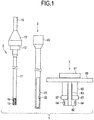
- Fig. 1 is a side view illustrating an entire configuration of an endoscope system
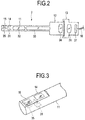
- Fig. 2 is a diagram schematically illustrating configurations of a bore scope and an image pickup device
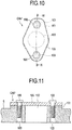
- Fig. 3 is a perspective view illustrating a configuration of a tip end portion of an insertion portion of the bore scope
- Fig. 4 is a sectional view illustrating a configuration of an endoscope guide device
- Fig. 5 is a side view illustrating a configuration of a fixture for endoscopic inspection
- Fig. 6 is a sectional view illustrating the configuration of the fixture for endoscopic inspection
- Fig. 7 is a plan view illustrating the configuration of the fixture for endoscopic inspection
- Fig. 8 is a bottom view illustrating the configuration of the fixture for endoscopic inspection
- Fig. 1 is a side view illustrating an entire configuration of an endoscope system
- Fig. 2 is a diagram schematically illustrating configurations of a bore scope and an image pickup device
- Fig. 3 is a perspective view illustrating
- FIG. 9 is a perspective view illustrating a state of an inspection of a jet engine
- Fig. 10 is a plan view illustrating a configuration of an external access port
- Fig. 11 is a sectional view illustrating the configuration of the external access port
- Fig. 12 is a sectional view illustrating a state in which the fixture for endoscopic inspection is inserted into the external access port
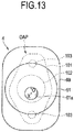
- Fig. 13 is a plan view illustrating the state in which the fixture for endoscopic inspection is inserted into the external access port
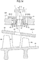
- Fig. 14 is a sectional view illustrating the state in which the fixture for endoscopic inspection is fixed to the external access port
- Fig. 15 is a sectional view illustrating a state in which the bore scope is inserted into the fixture for endoscopic inspection through the endoscope guide device
- Fig. 16 is a sectional view illustrating the state in which the fixture for endoscopic inspection is inserted into an external access port of a first variation of the aspect
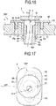
- Fig. 17 is a plan view illustrating the state in which the fixture for endoscopic inspection is inserted into an external access port of the embodiment of the invention.
- An endoscope system 1 mainly includes, as illustrated in Fig. 1 , a bore scope 2 as an endoscope, an endoscope guide device 3 to be inserted into a compressor portion of a jet engine and the like as an object for an inspection which will be described later, and a fixture 4 for endoscopic inspection into which the endoscope guide device 3 is inserted.
- the bore scope 2 here, is a side-view type endoscope, and has a cylindrical insertion portion 11 in which an observation window 14 and an illumination window 15 are provided on a side part of a distal end portion and an eyepiece portion 12 disposed at a proximal end portion of the insertion portion 11.
- a detachable image pickup apparatus 13 is mounted to the eyepiece portion 12 of the bore scope 2.
- observing means and illuminating means are arranged inside the bore scope 2. More specifically, as illustrated in Figs. 2 and 3 , in the insertion portion 11 of the bore scope 2, a mirror 31, an objective optical system 32, a relay optical system 33, and an LED 35 as the illuminating means, here, are arranged as an observation optical system. Note that, in the observation window 14 and the illumination window 15, transparent members such as glass are provided.
- the mirror 31 is arranged in the distal end portion of the insertion portion 11.
- the mirror 31 is an optical member which leads light entering the insertion portion 11 from a side surface of the bore scope 2 in a direction of the eyepiece portion 12.
- the objective optical system 32 is arranged on a distal end side of the bore scope 2 in the insertion portion 11 and is an optical member for forming a real image of an object.
- the LED 35 is an illumination light source emitting an illumination light toward the object and is connected to a wiring cable, not shown, disposed in the insertion portion 11, and a driving power is supplied by the wiring cable.
- the power for driving the LED 35 may be configured to be supplied from an outside, or a battery for supplying power may be configured to be provided in the bore scope 2.
- the illuminating means is not limited to the LED 35, and the illumination light from an external light source may be configured to be transmitted by a light guide bundle.
- an eyepiece optical system 34 for visualizing an image transmitted by the relay optical system 33 is provided in the eyepiece portion 12 of the bore scope 2.
- an image pickup optical system 36 and a solid image pickup device 37 are arranged in the image pickup apparatus 13 as a camera mounted on the eyepiece portion 12.
- the image pickup optical system 36 forms an image of an object visualized by the eyepiece portion 12 of the bore scope 2.
- the solid image pickup device 37 picks up an image of the object formed by the image pickup optical system 36.
- An image pickup signal which is a video signal photo-electrically converted in the solid image pickup device 37 is outputted to a personal computer (PC), not shown, via a signal cable 16.
- PC personal computer
- the image pickup signal from the solid image pickup device 37 may be configured to be outputted to a video processor or the like via the signal cable 16.
- the endoscope guide device 3 mainly includes an insertion portion guide tube 21 and a grasping portion 23 connected to a proximal end of the insertion portion guide tube 21 as illustrated in Fig. 4 .
- the insertion portion guide tube 21 is a rigid tube made of metal or the like with a distal end side closed into which the insertion portion 11 of the bore scope 2 can be removably inserted.
- the grasping portion 23 has an outer diameter larger than the insertion portion guide tube 21 so as to be grasped easily by a user.
- the insertion portion guide tube 21 has two observation opening portions 22 faced with each other as long holes along a longitudinal direction on a side peripheral portion from the distal end side to the middle (only one of them is shown in Fig. 4 ). These two observation opening portions 22 are window portions for enabling observation of an object by the bore scope 2 in a state in which the insertion portion 11 of the bore scope 2 is inserted into the insertion portion guide tube 21.
- the bore scope 2 becomes capable of observing an object by the bore scope 2 without a view field interfered by the insertion portion guide tube 21 with the observation window 14 and the illumination window 15 exposed from the observation opening portion 22.
- the fixture 4 for endoscopic inspection illustrated Figs. 5 to 8 (hereinafter referred to simply as a fixture for endoscopic inspection) includes a first columnar portion 61, a plurality of or three, here, arm portions 63 (only one of them is shown in Fig. 5 ), a second columnar portion 62, and a fixed cylinder portion 65.
- the three arm portions 63 are extended at substantially equal intervals around a periphery from the first columnar portion 62. Extended end portions of these three arm portions 63 are fixed to an outer peripheral portion of the second columnar portion.
- the fixed cylinder portion 65 is disposed between the first columnar portion 61 and the second columnar portion 62 and disposed capable of advance/retreat so as to be fitted in inner sides of the three arm portions 63.
- the second columnar portion 62 is connected by the three arm portions 63 extended from the first columnar portion 61, and the fixed cylinder portion 65 is disposed in the insides of these three arm portions 63.
- a first insertion hole 61a which is an insertion direction regulating portion formed having a hole axis X with a predetermined angle ⁇ formed with respect to a center axis O (see Figs. 6 and 7 ) is formed. That is, in the first insertion hole 61a, the hole axis X with the predetermined angle ⁇ is set to the center axis O in a longitudinal direction of the fixture 4 for endoscopic inspection.
- the second columnar portion 62 In the second columnar portion 62, three, here, projecting portions 64 (only two of them are shown in Fig. 5 ) projecting to an outer diameter direction are formed at substantially equal intervals on the outer peripheral portion. In the second columnar portion 62, too, a second insertion hole 62a which is an insertion direction regulating portion formed having the hole axis X with the predetermined angle ⁇ with respect to a center axis O (see Figs. 6 and 8 ) is formed.
- the hole axis X with the predetermined angle ⁇ is set to the center axis O in a longitudinal direction of the fixture 4 for endoscopic inspection, and the second insertion hole 62a also has the hole axis X coaxial with the first insertion hole 61a.
- the fixed cylinder portion 65 has three notch portions 66 formed from one of end portions which becomes the second columnar portion 62 side at positions along the arm portions 63 to the middle portion, respectively. Moreover, the fixed cylinder portion 65 has a diameter expanded portion 67 projecting to the outer diameter direction on the outer peripheral portion of the end portion on the second columnar portion 62 side.
- a taper 68 (see Fig. 6 ) is formed so as to expand in the one end portion direction on the second columnar portion 62 side.
- an outward flange 69 is provided on an end portion on a side of the first columnar portion 61.
- hole portions 69a into which the three arm portions 63 are inserted and an engagement recess portion 69b (see Figs. 6 and 8 ) as an installation direction regulating portion is formed on a surface on the second columnar portion 62 side.
- the engagement recess portion 69b has a shape similar to a projecting shape of an external access port OAP provided on a skin S of a jet engine E, not shown, here, which will be described later. Note that a configuration of the external access port OAP will be described later.
- the fixture 4 for endoscopic inspection is mounted on the jet engine E which is an object for an inspection (hereinafter referred to simply as an engine) as illustrated in Fig. 9 , and the endoscope guide device 3 is inserted into the fixture 4 for endoscopic inspection.
- the insertion portion 11 of the bore scope 2 is inserted, and an endoscopic inspection of a plurality of blades (hereinafter referred to as a rotor blade RB or a stator vane SV in some cases) inside the engine E which is an inspection target is conducted.
- a rotor blade RB or a stator vane SV in some cases a plurality of blades (hereinafter referred to as a rotor blade RB or a stator vane SV in some cases) inside the engine E which is an inspection target is conducted.
- the engine E has, as illustrated in Fig. 9 , an intake portion E1, a compressor portion E2, a combustion portion, and an exhaust portion (neither is not shown in detail) from the intake side toward the exhaust side.
- the compressor portion E2 is covered by a cylindrical skin S which becomes an exterior cover.
- the compressor portion E2 is an axial-flow type compressor and has a plurality of stages, in which a low-to-medium pressure compressor portion LMP and a high-pressure compressor portion HP are arranged in order from the intake side toward the exhaust side therein.
- a plurality of or six, here, external access ports OAP as access ports for endoscope on which the fixtures 4 for endoscopic inspection are installed, respectively, are provided.
- the insertion portion guide tubes 21 of the endoscope guide devices 3 are inserted.
- the bore scope 2 is inserted into the compressor portion E2 through the insertion portion guide tube 21.
- the endoscope system 1 inspects the plurality of rotor blades RB or stator vanes SV (neither is not shown, see Fig. 12 and the like) in the compressor portion E2 of the engine E by the endoscope guide device 3 and the bore scope 2 inserted into the fixture 4 for endoscopic inspection.
- the endoscopic inspection is conducted by connecting a turning tool T to the engine E.
- the turning tool T is a device for rotating a rotating shaft AR, includes a motor and a gearbox, and can rotate the rotating shaft AR through a shaft (not shown).
- a convex portion 101 projected and formed from the surface is provided as illustrated in Figs. 10 and 11 .
- an access hole portion 102 as a hole portion is drilled.
- two screw holes 103 for bolt tightening are formed.
- a lid body 105 covering the access hole portion 102 is mounted on the external access port OAP.
- the lid body 105 is fastened by screwing bolts 106 into the two screw holes.
- the lid body 105 of the external access port OAP on the skin S is removed.
- the fixture 4 for endoscopic inspection is inserted into the access hole portion 102 of the external access port OAP on the skin S from the second columnar portion 62 side.
- the fixed cylinder portion 65 is inserted into the access hole portion 102 to a position where the outward flange 69 is brought into contact with the convex portion 101 of the external access port OAP.
- a direction around the center axis O is adjusted to a correct position so that a shape of the engagement recess portion 69b formed on the outward flange 69 matches a shape of the convex portion 101 of the external access port OAP, and the engagement recess portion 69b and the convex portion 101 are engaged with each other.
- the first columnar portion 61 is pulled so that the second columnar portion 62 slides and enters into the fixed cylinder portion 65, and as illustrated in Fig. 14 , a diameter of one of end portions of the fixed cylinder portion 65 on the second columnar portion 62 side is expanded.
- the fixture 4 for endoscopic inspection if the first columnar portion 61 is pulled, the second columnar portion 62 slides with the three arm portions 63 and enters into the fixed cylinder portion 65.
- the second columnar portion 62 smoothly enters into the fixed cylinder portion 65 by the taper 68 of the fixed cylinder portion 65, and each of the three projecting portions 64 is brought into contact with an inner peripheral surface of the fixed cylinder portion 65. Then, in the fixed cylinder portion 65, three end piece portions divided by the three notch portions 66 are diameter-expanded in the outer diameter direction by contact of each of the projecting portions 64 with the inner peripheral surface.
- the fixture 4 for endoscopic inspection sandwiches an outer surface and an inner surface around the access hole portion 102 of the external access port OAP provided on the skin S by the outward flange 69 and the three diameter expanded portions 67 of the fixed cylinder portion 65.
- the second columnar portion 62 slides with the three arm portions 63 and enters into the fixed cylinder portion 65, and the three end piece portions divided by the three notch portions 66 are diameter-expanded in the outer diameter direction.
- the outward flange 69 of the fixed cylinder portion 65 is abutted on the outer surface of the convex portion 101 around the access hole portion 102 of the external access port OAP, the diameter expanded portion 67 formed on the diameter-expanded three end piece portions of the fixed cylinder portion 65 is caught by the inner surface around the access hole portion 102 of the external access port OAP, and the fixture 4 for endoscopic inspection is fixed to the external access port OAP so that the thickness direction of the skin S is sandwiched by the outward flange 69 and the three diameter expanded portions 67. As a result, the fixture 4 for endoscopic inspection is firmly fixed to the external access port OAP.
- the fixture 4 for endoscopic inspection is positioned in a state in which the insertion direction into the access hole portion 102 of the external access port OAP is regulated. Then, the fixture 4 for endoscopic inspection is fixed to the external access port OAP since the first columnar portion 61 is pulled toward a hand side.
- the first insertion hole 61a and the second insertion hole 62a formed in the first columnar portion 61 and the second columnar portion 62 of the fixture 4 for endoscopic inspection are regulated so that an extension of the common hole axis X passes in the vicinity of the opening center of the hole portion of an internal access port IAP as an access port for an endoscope formed on an exterior shroud OS of the low-to-medium pressure compressor portion LMP or the high-pressure compressor portion HP of the engine E.
- the insertion portion guide tube 21 of the endoscope guide device 3 is inserted, and the insertion portion 11 of the bore scope 2 is inserted into the insertion portion guide tube 21.
- an endoscopic inspection of the stator vane SV or the rotor blade RB in the low-to-medium pressure compressor portion LMP or the high-pressure compressor portion HP is conducted.
- the engagement recess portion 69b of the outward flange 69 is engaged with the convex portion 101 of the external access port OAP, whereby the installation direction of the fixture 4 for endoscopic inspection is uniquely determined, and an access direction of inserting the insertion portion guide tube 21 and the bore scope 2 of the endoscope guide device 3 into the low-to-medium pressure compressor portion LMP or the high-pressure compressor portion HP of the engine E is regulated by the first insertion hole 61a and the second insertion hole 62a.
- the insertion portion guide tube 21 of the endoscope guide device 3 can be smoothly inserted without being brought into contact with the internal access port IAP of the exterior shroud OS, contact or being caught.
- the endoscope guide device 3 in the endoscope system 1, even if the hole axes of the external access port OAP provided on the skin S side of the engine E and the internal access port IAP provided on the exterior shroud OS side are not coaxial but have a predetermined angle, by inserting the endoscope guide device 3 in the access direction connecting the external access port OAP and the internal access port IAP, the access direction of the bore scope 2 can be easily positioned by the fixture 4 for endoscopic inspection.
- the insertion direction of the bore scope 2 can be reliably regulated through the endoscope guide device 3 so that the insertion direction matches the access direction into the engine E.
- a shape of the convex portion 101 of the external access port OAP of the engine E might be different depending on a model of the engine E or a spot of each of the external access ports OAP in the same engine E.
- the shape of the engagement recess portion 69b formed on the outward flange 69 of the fixture 4 for endoscopic inspection is set individually so as to match the respective shapes exclusively.
- the access direction of the bore scope 2 into the engine E might be different also depending on the model of the engine E or a combination spot of each of the external access ports OAP and each of the internal access ports IAP in the same engine E.
- an inclination angle (the above described predetermined angle ⁇ ) of the first insertion hole 61a and the second insertion hole 62a as the insertion direction regulating portion formed on the fixture 4 for endoscopic inspection is set as appropriate in accordance with the model of the engine E or the combination spot of each of the external access ports OAP and each of the internal access ports IAP.
- the inclination angle of the first insertion hole 61a and the second insertion hole 62a as the insertion direction regulating portion formed on the fixture 4 for endoscopic inspection is set as appropriate in accordance with the access direction connecting the external access port OAP and the internal access port IAP.
- the configuration in which the bore scope 2 is inserted into the first insertion hole 61a and the second insertion hole 62a of the fixture 4 for endoscopic inspection through the endoscope guide device 3 is exemplified in the above, but this is not limiting, and the bore scope 2 may be inserted directly into the first insertion hole 61a and the second insertion hole 62a of the fixture 4 for endoscopic inspection.
- the fixture 4 for endoscopic inspection and the insertion portion guide tube 21 may be integrated.
- fixture 4 for endoscopic inspection may be as follows in relation with the configuration of the installation direction regulating portion for uniquely positioning the installation direction into the external access port OAP.
- the engagement recess portion 69b is not formed on the outward flange 69, and two projecting portions 71 as installation direction regulating portions engageably inserted into the two screw holes 103 for bolt tightening of the external access port OAP provided on the skin S are provided on the outward flange 69.
- These two projecting portions 71 are extended in a direction of the second columnar portion 62 from a rear surface side faced with the surface of the convex portion 101 of the outward flange 69.
- the fixture 4 for endoscopic inspection configured as above, when the fixed cylinder portion 65 is inserted into the access hole portion 102 of the external access port OAP, by engageably inserting the two projecting portions 71 in the screw holes 103, respectively, the direction around the center axis O is adjusted to a correct position.
- the outward flange 69 is inserted into the access hole portion 102 to a position in contact with the convex portion 101 of the external access port OAP.
- the first columnar portion 61 is pulled so that the second columnar portion 62 slides and enters into the fixed cylinder portion 65 and fixed to the external access port OAP as described above.
- the configuration of the fixture 4 for endoscopic inspection of this modification is based on the configuration in which the two screw holes 103 for bolt tightening of the external access port OAP are not provided point symmetric to the center axis of the access hole portion 102 (common to the center axis O of the fixture 4 for endoscopic inspection to be installed).
- a correct position where the fixed cylinder portion 65 is inserted into the access hole portion 102 of the external access port OAP may be regulated by providing a mark 72 as an index portion which becomes an installation direction regulating portion on a surface of the first columnar portion 61 and by matching this mark 72 with a flow direction of air (indicated by an arrow) flowing from an intake side toward an exhaust side of the engine E.
- the direction around the center axis O can be adjusted to a correct position by matching the mark 72 to the flow direction of the air of the engine E.
Description
- The present invention relates to a fixture for endoscopic inspection which regulates an insertion direction of an endoscope and particularly relates to a fixture for endoscopic inspection installed in an inspection of a blade of an engine and the like.
- Recently, in inspecting a blade of a jet engine and the like, an endoscope device in which an insertion portion is inserted into the jet engine and a defect inspection of a blade is made by using a picked up inspection image of the blade is widely used.
- Such a prior-art endoscope device technology is disclosed in Japanese Patent Application Laid-Open Publication No.
2007-163723 2007-163723 - In the jet engine, an external access port provided as an exterior cover of the jet engine on a skin side and a hole axis of an internal access port provided on an outer shroud side of a jet engine body are not coaxial, and even if a prior-art fixture is installed on the access port on the skin side, the endoscope inserted into this fixture cannot pass through the internal access port on the outer shroud side, and there is a problem that the blade in the jet engine cannot be observed.
- Thus, a configuration in which an insertion direction of the endoscope is regulated by matching an axial direction connecting the external access port on the skin side to the internal access port on the outer shroud side with an access direction of the endoscope can be provided in the fixture, but it is extremely difficult to install the fixture so that the insertion direction of the endoscope having an angle is matched with the access direction on the jet engine side.
- Therefore, depending on an installation position of the fixture, the insertion direction of the endoscope regulated by the fixture is not matched with the access direction to the jet engine, and even if the fixture is installed at the external access port on the skin side, such a problem is caused that the endoscope cannot pass through the internal access port on the outer shroud side.
- From document
US 4 298 312 A , a method is known for inserting a radiation passing cable having a probe end into a jet engine, wherein the probe end is inserted through the housing of the engine and between stator vanes of the jet engine. - Thus, the present invention has an object to provide a fixture for endoscopic inspection which can reliably regulate the insertion direction of the endoscope so that the insertion direction matches the access direction to the jet engine.
- This object is solved by the device according to
claim 1. - According to the present invention, the fixture for endoscopic inspection which can reliably regulate the insertion direction of the endoscope so that the insertion direction matches the access direction to the jet engine can be provided.
- The above and other objects, features and advantages of the invention will become more clearly understood from the following description referring to the accompanying drawings.
-
-
Fig. 1 is a side view illustrating a configuration of an endoscope system; -
Fig. 2 is a diagram schematically illustrating configurations of a bore scope and an image pickup device; -
Fig. 3 is a perspective view illustrating a configuration of a tip end portion of an insertion portion of the bore scope; -
Fig. 4 is a sectional view illustrating a configuration of an endoscope guide device; -
Fig. 5 is a side view illustrating a configuration of a fixture for endoscopic inspection; -
Fig. 6 is a sectional view illustrating the configuration of the fixture for endoscopic inspection; -
Fig. 7 is a plan view illustrating the configuration of the fixture for endoscopic inspection; -
Fig. 8 is a bottom view illustrating the configuration of the fixture for endoscopic inspection; -
Fig. 9 is a perspective view illustrating a state of an inspection of a jet engine; -
Fig. 10 is a plan view illustrating a configuration of an external access port -
Fig. 11 is a sectional view illustrating the configuration of the external access port; -
Fig. 12 is a sectional view illustrating a state in which the fixture for endoscopic inspection is inserted into the external access port; -
Fig. 13 is a plan view illustrating the state in which the fixture for endoscopic inspection is inserted into the external access port; -
Fig. 14 is a sectional view illustrating the state in which the fixture for endoscopic inspection is fixed to the external access port; -
Fig. 15 is a sectional view illustrating a state in which the bore scope is inserted into the fixture for endoscopic inspection through the endoscope guide device; -
Fig. 16 is a sectional view illustrating the state in which the fixture for endoscopic inspection is inserted into an external access port; and -
Fig. 17 is a plan view illustrating the state in which the fixture for endoscopic inspection is inserted into an external access port of a aspect of the present invention. - Embodiments of the present invention will be described below by referring to the attached drawings.
- Note that, in the following explanation, the figures are schematic and a relationship between a thickness and a width of each portion, a ratio of thickness of the respective portions and the like are different from real ones, and even among the figures, those with different relationships of dimensions or different ratios might be included.
- First, an endoscope system of will be described below on the basis of the drawings.
-
Fig. 1 is a side view illustrating an entire configuration of an endoscope system,Fig. 2 is a diagram schematically illustrating configurations of a bore scope and an image pickup device,Fig. 3 is a perspective view illustrating a configuration of a tip end portion of an insertion portion of the bore scope,Fig. 4 is a sectional view illustrating a configuration of an endoscope guide device,Fig. 5 is a side view illustrating a configuration of a fixture for endoscopic inspection,Fig. 6 is a sectional view illustrating the configuration of the fixture for endoscopic inspection,Fig. 7 is a plan view illustrating the configuration of the fixture for endoscopic inspection,Fig. 8 is a bottom view illustrating the configuration of the fixture for endoscopic inspection,Fig. 9 is a perspective view illustrating a state of an inspection of a jet engine,Fig. 10 is a plan view illustrating a configuration of an external access port,Fig. 11 is a sectional view illustrating the configuration of the external access port,Fig. 12 is a sectional view illustrating a state in which the fixture for endoscopic inspection is inserted into the external access port,Fig. 13 is a plan view illustrating the state in which the fixture for endoscopic inspection is inserted into the external access port,Fig. 14 is a sectional view illustrating the state in which the fixture for endoscopic inspection is fixed to the external access port,Fig. 15 is a sectional view illustrating a state in which the bore scope is inserted into the fixture for endoscopic inspection through the endoscope guide device,Fig. 16 is a sectional view illustrating the state in which the fixture for endoscopic inspection is inserted into an external access port of a first variation of the aspect, andFig. 17 is a plan view illustrating the state in which the fixture for endoscopic inspection is inserted into an external access port of the embodiment of the invention. - An
endoscope system 1 mainly includes, as illustrated inFig. 1 , abore scope 2 as an endoscope, anendoscope guide device 3 to be inserted into a compressor portion of a jet engine and the like as an object for an inspection which will be described later, and afixture 4 for endoscopic inspection into which theendoscope guide device 3 is inserted. - The
bore scope 2, here, is a side-view type endoscope, and has acylindrical insertion portion 11 in which anobservation window 14 and anillumination window 15 are provided on a side part of a distal end portion and aneyepiece portion 12 disposed at a proximal end portion of theinsertion portion 11. Note that, here, a detachableimage pickup apparatus 13 is mounted to theeyepiece portion 12 of thebore scope 2. - Inside the
bore scope 2, observing means and illuminating means are arranged. More specifically, as illustrated inFigs. 2 and 3 , in theinsertion portion 11 of thebore scope 2, amirror 31, an objectiveoptical system 32, a relayoptical system 33, and anLED 35 as the illuminating means, here, are arranged as an observation optical system. Note that, in theobservation window 14 and theillumination window 15, transparent members such as glass are provided. - The
mirror 31 is arranged in the distal end portion of theinsertion portion 11. Themirror 31 is an optical member which leads light entering theinsertion portion 11 from a side surface of thebore scope 2 in a direction of theeyepiece portion 12. The objectiveoptical system 32 is arranged on a distal end side of thebore scope 2 in theinsertion portion 11 and is an optical member for forming a real image of an object. - The
LED 35 is an illumination light source emitting an illumination light toward the object and is connected to a wiring cable, not shown, disposed in theinsertion portion 11, and a driving power is supplied by the wiring cable. - Note that the power for driving the
LED 35 may be configured to be supplied from an outside, or a battery for supplying power may be configured to be provided in thebore scope 2. Moreover, the illuminating means is not limited to theLED 35, and the illumination light from an external light source may be configured to be transmitted by a light guide bundle. - In the
eyepiece portion 12 of thebore scope 2, an eyepieceoptical system 34 for visualizing an image transmitted by the relayoptical system 33 is provided. In theimage pickup apparatus 13 as a camera mounted on theeyepiece portion 12, an image pickupoptical system 36 and a solidimage pickup device 37 are arranged. - The image pickup
optical system 36 forms an image of an object visualized by theeyepiece portion 12 of thebore scope 2. The solidimage pickup device 37 picks up an image of the object formed by the image pickupoptical system 36. - An image pickup signal which is a video signal photo-electrically converted in the solid
image pickup device 37 is outputted to a personal computer (PC), not shown, via asignal cable 16. Note that the image pickup signal from the solidimage pickup device 37 may be configured to be outputted to a video processor or the like via thesignal cable 16. - Since the components of the
bore scope 2 and theimage pickup apparatus 13 described above are known, detailed explanation of the other components will be omitted. - Subsequently, the
endoscope guide device 3 will be described below. - The
endoscope guide device 3 mainly includes an insertionportion guide tube 21 and agrasping portion 23 connected to a proximal end of the insertionportion guide tube 21 as illustrated inFig. 4 . - The insertion
portion guide tube 21 is a rigid tube made of metal or the like with a distal end side closed into which theinsertion portion 11 of thebore scope 2 can be removably inserted. Note that thegrasping portion 23 has an outer diameter larger than the insertionportion guide tube 21 so as to be grasped easily by a user. - The insertion
portion guide tube 21 has twoobservation opening portions 22 faced with each other as long holes along a longitudinal direction on a side peripheral portion from the distal end side to the middle (only one of them is shown inFig. 4 ). These twoobservation opening portions 22 are window portions for enabling observation of an object by thebore scope 2 in a state in which theinsertion portion 11 of thebore scope 2 is inserted into the insertionportion guide tube 21. - That is, the
bore scope 2 becomes capable of observing an object by thebore scope 2 without a view field interfered by the insertionportion guide tube 21 with theobservation window 14 and theillumination window 15 exposed from theobservation opening portion 22. - Subsequently, the
fixture 4 for endoscopic inspection will be described below. - The
fixture 4 for endoscopic inspection illustratedFigs. 5 to 8 (hereinafter referred to simply as a fixture for endoscopic inspection) includes a firstcolumnar portion 61, a plurality of or three, here, arm portions 63 (only one of them is shown inFig. 5 ), a secondcolumnar portion 62, and a fixedcylinder portion 65. - Note that the three
arm portions 63 are extended at substantially equal intervals around a periphery from the firstcolumnar portion 62. Extended end portions of these threearm portions 63 are fixed to an outer peripheral portion of the second columnar portion. - The fixed
cylinder portion 65 is disposed between the firstcolumnar portion 61 and the secondcolumnar portion 62 and disposed capable of advance/retreat so as to be fitted in inner sides of the threearm portions 63. - That is, in the
fixture 4 for endoscopic inspection, the secondcolumnar portion 62 is connected by the threearm portions 63 extended from the firstcolumnar portion 61, and the fixedcylinder portion 65 is disposed in the insides of these threearm portions 63. - In the first
columnar portion 61, afirst insertion hole 61a which is an insertion direction regulating portion formed having a hole axis X with a predetermined angle θ formed with respect to a center axis O (seeFigs. 6 and7 ) is formed. That is, in thefirst insertion hole 61a, the hole axis X with the predetermined angle θ is set to the center axis O in a longitudinal direction of thefixture 4 for endoscopic inspection. - In the second
columnar portion 62, three, here, projecting portions 64 (only two of them are shown inFig. 5 ) projecting to an outer diameter direction are formed at substantially equal intervals on the outer peripheral portion. In the secondcolumnar portion 62, too, asecond insertion hole 62a which is an insertion direction regulating portion formed having the hole axis X with the predetermined angle θ with respect to a center axis O (seeFigs. 6 and8 ) is formed. That is, in thesecond insertion hole 62a, too, the hole axis X with the predetermined angle θ is set to the center axis O in a longitudinal direction of thefixture 4 for endoscopic inspection, and thesecond insertion hole 62a also has the hole axis X coaxial with thefirst insertion hole 61a. - The fixed
cylinder portion 65 has threenotch portions 66 formed from one of end portions which becomes the secondcolumnar portion 62 side at positions along thearm portions 63 to the middle portion, respectively. Moreover, the fixedcylinder portion 65 has a diameter expandedportion 67 projecting to the outer diameter direction on the outer peripheral portion of the end portion on the secondcolumnar portion 62 side. - Then, in the fixed
cylinder portion 65, on an inner surface side of the diameter expandedportion 67, a taper 68 (seeFig. 6 ) is formed so as to expand in the one end portion direction on the secondcolumnar portion 62 side. - In the fixed
cylinder portion 65, anoutward flange 69 is provided on an end portion on a side of the firstcolumnar portion 61. In theoutward flange 69,hole portions 69a into which the threearm portions 63 are inserted and anengagement recess portion 69b (seeFigs. 6 and8 ) as an installation direction regulating portion is formed on a surface on the secondcolumnar portion 62 side. - The
engagement recess portion 69b has a shape similar to a projecting shape of an external access port OAP provided on a skin S of a jet engine E, not shown, here, which will be described later. Note that a configuration of the external access port OAP will be described later. - In the
endoscope system 1 configured as above, thefixture 4 for endoscopic inspection is mounted on the jet engine E which is an object for an inspection (hereinafter referred to simply as an engine) as illustrated inFig. 9 , and theendoscope guide device 3 is inserted into thefixture 4 for endoscopic inspection. - Then, into the insertion
portion guide tube 21, theinsertion portion 11 of thebore scope 2 is inserted, and an endoscopic inspection of a plurality of blades (hereinafter referred to as a rotor blade RB or a stator vane SV in some cases) inside the engine E which is an inspection target is conducted. - Here, the engine E will be described in brief.
- The engine E has, as illustrated in
Fig. 9 , an intake portion E1, a compressor portion E2, a combustion portion, and an exhaust portion (neither is not shown in detail) from the intake side toward the exhaust side. - The compressor portion E2 is covered by a cylindrical skin S which becomes an exterior cover. The compressor portion E2 is an axial-flow type compressor and has a plurality of stages, in which a low-to-medium pressure compressor portion LMP and a high-pressure compressor portion HP are arranged in order from the intake side toward the exhaust side therein.
- In the skin S, a plurality of or six, here, external access ports OAP as access ports for endoscope on which the
fixtures 4 for endoscopic inspection are installed, respectively, are provided. Into thefixtures 4 for endoscopic inspection installed on these external access ports OAP, respectively, the insertionportion guide tubes 21 of theendoscope guide devices 3 are inserted. Then, thebore scope 2 is inserted into the compressor portion E2 through the insertionportion guide tube 21. - As described above, the
endoscope system 1 inspects the plurality of rotor blades RB or stator vanes SV (neither is not shown, seeFig. 12 and the like) in the compressor portion E2 of the engine E by theendoscope guide device 3 and thebore scope 2 inserted into thefixture 4 for endoscopic inspection. - The endoscopic inspection is conducted by connecting a turning tool T to the engine E. The turning tool T is a device for rotating a rotating shaft AR, includes a motor and a gearbox, and can rotate the rotating shaft AR through a shaft (not shown).
- Then, in the endoscopic inspection, while the plurality of rotor blades which will be described later are rotated around the rotating shaft AR by using the turning tool T, the plurality of rotor blades provided on the rotating shaft AR are photographed by the
bore scope 2 inserted into the compressor portion E2 and the endoscopic inspection is conducted. - On the external access port OAP provided on the skin S, a
convex portion 101 projected and formed from the surface is provided as illustrated inFigs. 10 and 11 . At a center of theconvex portion 101, anaccess hole portion 102 as a hole portion is drilled. Moreover, on both sides of theaccess hole portion 102, twoscrew holes 103 for bolt tightening are formed. - On the external access port OAP, a
lid body 105 covering theaccess hole portion 102 is mounted when an endoscopic inspection is not conducted. Thelid body 105 is fastened by screwingbolts 106 into the two screw holes. - Here, an operation of fixing the
fixture 4 for endoscopic inspection which regulates an insertion direction of theendoscope guide device 3 to the compressor portion E2 of the engine E by installing thefixture 4 for endoscopic inspection on the external access port OAP on the skin S in an endoscopic inspection conducted by theendoscope system 1 will be described. - First, the
lid body 105 of the external access port OAP on the skin S is removed. Then, thefixture 4 for endoscopic inspection is inserted into theaccess hole portion 102 of the external access port OAP on the skin S from the secondcolumnar portion 62 side. - At this time, in the
fixture 4 for endoscopic inspection, as illustrated inFig. 12 , the fixedcylinder portion 65 is inserted into theaccess hole portion 102 to a position where theoutward flange 69 is brought into contact with theconvex portion 101 of the external access port OAP. - Note that, in the
fixture 4 for endoscopic inspection, as illustrated inFig. 13 , a direction around the center axis O is adjusted to a correct position so that a shape of theengagement recess portion 69b formed on theoutward flange 69 matches a shape of theconvex portion 101 of the external access port OAP, and theengagement recess portion 69b and theconvex portion 101 are engaged with each other. - From this state, in the
fixture 4 for endoscopic inspection, the firstcolumnar portion 61 is pulled so that the secondcolumnar portion 62 slides and enters into the fixedcylinder portion 65, and as illustrated inFig. 14 , a diameter of one of end portions of the fixedcylinder portion 65 on the secondcolumnar portion 62 side is expanded. - More specifically, in the
fixture 4 for endoscopic inspection, if the firstcolumnar portion 61 is pulled, the secondcolumnar portion 62 slides with the threearm portions 63 and enters into the fixedcylinder portion 65. - At this time, the second
columnar portion 62 smoothly enters into the fixedcylinder portion 65 by thetaper 68 of the fixedcylinder portion 65, and each of the three projectingportions 64 is brought into contact with an inner peripheral surface of the fixedcylinder portion 65. Then, in the fixedcylinder portion 65, three end piece portions divided by the threenotch portions 66 are diameter-expanded in the outer diameter direction by contact of each of the projectingportions 64 with the inner peripheral surface. - As a result, the
fixture 4 for endoscopic inspection sandwiches an outer surface and an inner surface around theaccess hole portion 102 of the external access port OAP provided on the skin S by theoutward flange 69 and the three diameter expandedportions 67 of the fixedcylinder portion 65. - That is, when the first
columnar portion 61 is pulled, the secondcolumnar portion 62 slides with the threearm portions 63 and enters into the fixedcylinder portion 65, and the three end piece portions divided by the threenotch portions 66 are diameter-expanded in the outer diameter direction. - Then, the
outward flange 69 of the fixedcylinder portion 65 is abutted on the outer surface of theconvex portion 101 around theaccess hole portion 102 of the external access port OAP, the diameter expandedportion 67 formed on the diameter-expanded three end piece portions of the fixedcylinder portion 65 is caught by the inner surface around theaccess hole portion 102 of the external access port OAP, and thefixture 4 for endoscopic inspection is fixed to the external access port OAP so that the thickness direction of the skin S is sandwiched by theoutward flange 69 and the three diameter expandedportions 67. As a result, thefixture 4 for endoscopic inspection is firmly fixed to the external access port OAP. - As described above, since the
engagement recess portion 69b formed on theoutward flange 69 is engaged with theconvex portion 101 of the external access port OAP, thefixture 4 for endoscopic inspection is positioned in a state in which the insertion direction into theaccess hole portion 102 of the external access port OAP is regulated. Then, thefixture 4 for endoscopic inspection is fixed to the external access port OAP since the firstcolumnar portion 61 is pulled toward a hand side. - In this state, the
first insertion hole 61a and thesecond insertion hole 62a formed in the firstcolumnar portion 61 and the secondcolumnar portion 62 of thefixture 4 for endoscopic inspection are regulated so that an extension of the common hole axis X passes in the vicinity of the opening center of the hole portion of an internal access port IAP as an access port for an endoscope formed on an exterior shroud OS of the low-to-medium pressure compressor portion LMP or the high-pressure compressor portion HP of the engine E. - Then, into the
first insertion hole 61a and thesecond insertion hole 62a of thefixture 4 for endoscopic inspection, as illustrated inFig. 15 , the insertionportion guide tube 21 of theendoscope guide device 3 is inserted, and theinsertion portion 11 of thebore scope 2 is inserted into the insertionportion guide tube 21. As described above, an endoscopic inspection of the stator vane SV or the rotor blade RB in the low-to-medium pressure compressor portion LMP or the high-pressure compressor portion HP is conducted. - As described above, in the
endoscope system 1 when thefixture 4 for endoscopic inspection is fixed to the external access port OAP, theengagement recess portion 69b of theoutward flange 69 is engaged with theconvex portion 101 of the external access port OAP, whereby the installation direction of thefixture 4 for endoscopic inspection is uniquely determined, and an access direction of inserting the insertionportion guide tube 21 and thebore scope 2 of theendoscope guide device 3 into the low-to-medium pressure compressor portion LMP or the high-pressure compressor portion HP of the engine E is regulated by thefirst insertion hole 61a and thesecond insertion hole 62a. - That is, by being inserted into the
first insertion hole 61a and thesecond insertion hole 62a of thefixture 4 for endoscopic inspection, the insertionportion guide tube 21 of theendoscope guide device 3 can be smoothly inserted without being brought into contact with the internal access port IAP of the exterior shroud OS, contact or being caught. - Therefore, in the
endoscope system 1, even if the hole axes of the external access port OAP provided on the skin S side of the engine E and the internal access port IAP provided on the exterior shroud OS side are not coaxial but have a predetermined angle, by inserting theendoscope guide device 3 in the access direction connecting the external access port OAP and the internal access port IAP, the access direction of thebore scope 2 can be easily positioned by thefixture 4 for endoscopic inspection. - As a result, in the
fixture 4 for endoscopic inspection, the insertion direction of thebore scope 2 can be reliably regulated through theendoscope guide device 3 so that the insertion direction matches the access direction into the engine E. - Note that a shape of the
convex portion 101 of the external access port OAP of the engine E might be different depending on a model of the engine E or a spot of each of the external access ports OAP in the same engine E. - Thus, the shape of the
engagement recess portion 69b formed on theoutward flange 69 of thefixture 4 for endoscopic inspection is set individually so as to match the respective shapes exclusively. - Moreover, the access direction of the
bore scope 2 into the engine E might be different also depending on the model of the engine E or a combination spot of each of the external access ports OAP and each of the internal access ports IAP in the same engine E. - Thus, an inclination angle (the above described predetermined angle θ) of the
first insertion hole 61a and thesecond insertion hole 62a as the insertion direction regulating portion formed on thefixture 4 for endoscopic inspection is set as appropriate in accordance with the model of the engine E or the combination spot of each of the external access ports OAP and each of the internal access ports IAP. - That is, the inclination angle of the
first insertion hole 61a and thesecond insertion hole 62a as the insertion direction regulating portion formed on thefixture 4 for endoscopic inspection is set as appropriate in accordance with the access direction connecting the external access port OAP and the internal access port IAP. - Moreover, the configuration in which the
bore scope 2 is inserted into thefirst insertion hole 61a and thesecond insertion hole 62a of thefixture 4 for endoscopic inspection through theendoscope guide device 3 is exemplified in the above, but this is not limiting, and thebore scope 2 may be inserted directly into thefirst insertion hole 61a and thesecond insertion hole 62a of thefixture 4 for endoscopic inspection. Moreover, thefixture 4 for endoscopic inspection and the insertionportion guide tube 21 may be integrated. - Note that the
fixture 4 for endoscopic inspection may be as follows in relation with the configuration of the installation direction regulating portion for uniquely positioning the installation direction into the external access port OAP. - As illustrated in
Fig. 16 , in thefixture 4 for endoscopic inspection of this modification, theengagement recess portion 69b is not formed on theoutward flange 69, and two projectingportions 71 as installation direction regulating portions engageably inserted into the twoscrew holes 103 for bolt tightening of the external access port OAP provided on the skin S are provided on theoutward flange 69. These two projectingportions 71 are extended in a direction of the secondcolumnar portion 62 from a rear surface side faced with the surface of theconvex portion 101 of theoutward flange 69. - In the
fixture 4 for endoscopic inspection configured as above, when the fixedcylinder portion 65 is inserted into theaccess hole portion 102 of the external access port OAP, by engageably inserting the two projectingportions 71 in the screw holes 103, respectively, the direction around the center axis O is adjusted to a correct position. - Then, in the
fixture 4 for endoscopic inspection, theoutward flange 69 is inserted into theaccess hole portion 102 to a position in contact with theconvex portion 101 of the external access port OAP. - After that, in the
fixture 4 for endoscopic inspection, the firstcolumnar portion 61 is pulled so that the secondcolumnar portion 62 slides and enters into the fixedcylinder portion 65 and fixed to the external access port OAP as described above. - With such configuration, too, in this modification, when the
fixture 4 for endoscopic inspection is fixed to the external access port OAP, each of the two projectingportions 71 is engageably inserted into thescrew hole 103, whereby the installation direction of thefixture 4 for endoscopic inspection is uniquely determined. As a result, the access direction of inserting the insertionportion guide tube 21 and thebore scope 2 of theendoscope guide device 3 into the low-to-medium pressure compressor portion LMP or the high-pressure compressor portion HP of the engine E is regulated by thefirst insertion hole 61a and thesecond insertion hole 62a of thefixture 4 for endoscopic inspection. - Note that the configuration of the
fixture 4 for endoscopic inspection of this modification is based on the configuration in which the twoscrew holes 103 for bolt tightening of the external access port OAP are not provided point symmetric to the center axis of the access hole portion 102 (common to the center axis O of thefixture 4 for endoscopic inspection to be installed). - As illustrated in
Fig. 17 , in thefixture 4 for endoscopic inspection, a correct position where the fixedcylinder portion 65 is inserted into theaccess hole portion 102 of the external access port OAP may be regulated by providing amark 72 as an index portion which becomes an installation direction regulating portion on a surface of the firstcolumnar portion 61 and by matching thismark 72 with a flow direction of air (indicated by an arrow) flowing from an intake side toward an exhaust side of the engine E. - That is, in the
fixture 4 for endoscopic inspection, when the fixedcylinder portion 65 is inserted into theaccess hole portion 102 of the external access port OAP, the direction around the center axis O can be adjusted to a correct position by matching themark 72 to the flow direction of the air of the engine E.
Claims (1)
- A fixture (4) for endoscopic inspection configured to be fixed to an access port for an endoscope (2) of an engine (E) which has a flow direction of air, comprising:a first columnar portion (61) having a first insertion direction regulating portion (61a) and a second columnar portion (62) having a second insertion direction regulation portion (62a), said first and second insertion direction regulation portions (61a, 62a) being adapted to regulate an access direction of an insertion portion (11) of an endoscope (2) connecting an external access port (OAP) disposed on an exterior cover (S) of the engine (E) to an internal access port (IAP) disposed on an exterior shroud (OS) of the engine (E); andan installation direction regulating portion (69b, 71, 72), being adapted to uniquely regulate an installation direction of the fixture (4) so that the insertion direction regulating portion matches the access direction at a time of attachment to the external access port,said first and second columnar portions (61, 62) defining a center axis (O),each of the first and second insertion direction regulating portions (61a, 62a) having a hole axis (X) with a predetermined inclination angle (θ) with respect to the center axis (O) in a longitudinal direction of the first and second columnar portions (61, 62),wherein the installation direction regulating portion (69b, 71, 72) is an index (72) on a surface of the first columnar portion (61); andby matching the index with the flow direction of air of the engine, the installation direction is uniquely regulated so that the installation direction matches the access direction.
Applications Claiming Priority (1)
| Application Number | Priority Date | Filing Date | Title |
|---|---|---|---|
| JP2013160750A JP6218484B2 (en) | 2013-08-01 | 2013-08-01 | Endoscopy fixture |
Publications (2)
| Publication Number | Publication Date |
|---|---|
| EP2833189A1 EP2833189A1 (en) | 2015-02-04 |
| EP2833189B1 true EP2833189B1 (en) | 2019-09-04 |
Family
ID=51212776
Family Applications (1)
| Application Number | Title | Priority Date | Filing Date |
|---|---|---|---|
| EP14178326.6A Active EP2833189B1 (en) | 2013-08-01 | 2014-07-24 | Fixture for endoscopic inspection |
Country Status (3)
| Country | Link |
|---|---|
| US (1) | US9766159B2 (en) |
| EP (1) | EP2833189B1 (en) |
| JP (1) | JP6218484B2 (en) |
Families Citing this family (11)
| Publication number | Priority date | Publication date | Assignee | Title |
|---|---|---|---|---|
| JP6599722B2 (en) * | 2015-10-15 | 2019-10-30 | オリンパス株式会社 | Inspection device |
| US10197473B2 (en) * | 2015-12-09 | 2019-02-05 | General Electric Company | System and method for performing a visual inspection of a gas turbine engine |
| GB2553144B (en) | 2016-08-26 | 2019-10-30 | Rolls Royce Plc | Apparatus for insertion into a cavity of an object |
| DE102017218426B3 (en) | 2017-10-16 | 2019-01-17 | Lufthansa Technik Ag | Apparatus and method for borescope inspection of jet engines |
| JP2021126131A (en) * | 2018-03-19 | 2021-09-02 | オリンパス株式会社 | Endoscope system and guide member |
| FR3087535B1 (en) * | 2018-10-18 | 2020-11-13 | Safran Aircraft Engines | TOOLS AND METHOD FOR ENDOSCOPIC INSPECTION OF A MANIFOLD CASING OF AN AIRCRAFT TURBOMACHINE |
| DE102019213914A1 (en) * | 2019-09-12 | 2021-03-18 | Carl Zeiss Smt Gmbh | Device for cleaning a surface inside an optical system |
| US11513034B2 (en) | 2020-02-14 | 2022-11-29 | Raytheon Technologies Corporation | Probe adapter for a blade outer air seal and method for using same |
| CN113050185A (en) * | 2021-03-17 | 2021-06-29 | 中国航发动力股份有限公司 | Portable high-color-temperature turbine blade inner cavity inspection device and using method |
| CN113503211B (en) * | 2021-05-28 | 2023-09-22 | 华能苏州热电有限责任公司 | Tool capable of preventing lens from being clamped in-situ Kong Kui inspection of gas turbine |
| CN113504248B (en) * | 2021-06-18 | 2023-12-19 | 国营四达机械制造公司 | Auxiliary tool for hole detection of high-pressure compressor blade of aero-engine and checking method |
Family Cites Families (10)
| Publication number | Priority date | Publication date | Assignee | Title |
|---|---|---|---|---|
| US4298312A (en) | 1979-07-24 | 1981-11-03 | Purex Corporation | Damaged vane locating method and apparatus |
| US4711524A (en) | 1985-09-06 | 1987-12-08 | The United States Of America As Represented By The Secretary Of The Navy | Combustor fiberscope |
| JP2929473B2 (en) * | 1989-09-18 | 1999-08-03 | オリンパス光学工業株式会社 | Industrial endoscope device |
| JPH0534602A (en) * | 1991-07-29 | 1993-02-12 | Olympus Optical Co Ltd | Endoscope device |
| JPH05297286A (en) * | 1992-04-17 | 1993-11-12 | Olympus Optical Co Ltd | Endoscope device for industrial use |
| IL130799A (en) | 1999-07-05 | 2003-10-31 | Israel Aircraft Ind Ltd | Adapter for use in exhaust gas temperature measurement of a jet engine |
| US7458768B2 (en) * | 2005-06-28 | 2008-12-02 | United Technologies Corporation | Borescope inspection port device for gas turbine engine and gas turbine engine using same |
| JP4869699B2 (en) | 2005-12-13 | 2012-02-08 | オリンパス株式会社 | Endoscope device |
| US8197187B2 (en) * | 2008-12-29 | 2012-06-12 | Caterpillar Inc. | Inspection hole plug with a ball swivel |
| GB2496903B (en) * | 2011-11-28 | 2015-04-15 | Rolls Royce Plc | An apparatus and a method of inspecting a turbomachine |
-
2013
- 2013-08-01 JP JP2013160750A patent/JP6218484B2/en active Active
-
2014
- 2014-07-21 US US14/336,824 patent/US9766159B2/en active Active
- 2014-07-24 EP EP14178326.6A patent/EP2833189B1/en active Active
Non-Patent Citations (1)
| Title |
|---|
| None * |
Also Published As
| Publication number | Publication date |
|---|---|
| JP6218484B2 (en) | 2017-10-25 |
| US9766159B2 (en) | 2017-09-19 |
| US20150036130A1 (en) | 2015-02-05 |
| EP2833189A1 (en) | 2015-02-04 |
| JP2015031802A (en) | 2015-02-16 |
Similar Documents
| Publication | Publication Date | Title |
|---|---|---|
| EP2833189B1 (en) | Fixture for endoscopic inspection | |
| EP2818908B1 (en) | Endoscope system | |
| EP2833187B1 (en) | Blade inspection system | |
| JP7189947B2 (en) | Apparatus for jet engine borescope inspection and method for inspecting jet engine turbine blades | |
| US8400501B2 (en) | Inspection arrangement | |
| EP2833190B1 (en) | Blade inspection apparatus | |
| US10281712B2 (en) | Single-axis inspection scope with bendable knuckle and method for internal inspection of power generation machinery | |
| US10274718B2 (en) | Single-axis inspection scope with anti-rotation extension and method for internal inspection of power generation machinery | |
| US20150036150A1 (en) | Blade inspection apparatus and blade inspection method | |
| JPS62182706A (en) | Deflectable slender tubular inspector | |
| JPH1199126A (en) | Electronic endoscope | |
| EP3399160A1 (en) | Method of inspecting a gas turbine engine | |
| US20160278623A1 (en) | Heat resistant sheath for endoscope and endoscope system provided with heat resistant sheath for endoscope | |
| US9823460B2 (en) | Blade inspection apparatus and blade inspection method | |
| GB2036363A (en) | Inspecting Stator Vanes | |
| JPH05297284A (en) | Endoscope for industrial use | |
| JP4978375B2 (en) | Visualization device in exhaust pipe | |
| JP2709159B2 (en) | Endoscope device | |
| CN113504248B (en) | Auxiliary tool for hole detection of high-pressure compressor blade of aero-engine and checking method | |
| JP2836751B2 (en) | Endoscope tip attachment attachment device | |
| CN215867340U (en) | Endoscope in infrared spectroscopy industry | |
| JP2017026508A (en) | Inspection imaging instrument and inspection imaging method | |
| JPH04267213A (en) | Endoscope device | |
| JPH03158818A (en) | Industrial endoscope device | |
| JP2000121960A (en) | Portable endoscope |
Legal Events
| Date | Code | Title | Description |
|---|---|---|---|
| 17P | Request for examination filed |
Effective date: 20140724 |
|
| AK | Designated contracting states |
Kind code of ref document: A1 Designated state(s): AL AT BE BG CH CY CZ DE DK EE ES FI FR GB GR HR HU IE IS IT LI LT LU LV MC MK MT NL NO PL PT RO RS SE SI SK SM TR |
|
| AX | Request for extension of the european patent |
Extension state: BA ME |
|
| PUAI | Public reference made under article 153(3) epc to a published international application that has entered the european phase |
Free format text: ORIGINAL CODE: 0009012 |
|
| R17P | Request for examination filed (corrected) |
Effective date: 20150728 |
|
| RBV | Designated contracting states (corrected) |
Designated state(s): AL AT BE BG CH CY CZ DE DK EE ES FI FR GB GR HR HU IE IS IT LI LT LU LV MC MK MT NL NO PL PT RO RS SE SI SK SM TR |
|
| RAP1 | Party data changed (applicant data changed or rights of an application transferred) |
Owner name: OLYMPUS CORPORATION |
|
| RAP1 | Party data changed (applicant data changed or rights of an application transferred) |
Owner name: OLYMPUS CORPORATION |
|
| RIN1 | Information on inventor provided before grant (corrected) |
Inventor name: HORI, FUMIO Inventor name: KONOMURA, YUTAKA Inventor name: KOBAYASHI, EIICHI |
|
| STAA | Information on the status of an ep patent application or granted ep patent |
Free format text: STATUS: EXAMINATION IS IN PROGRESS |
|
| 17Q | First examination report despatched |
Effective date: 20170522 |
|
| RIC1 | Information provided on ipc code assigned before grant |
Ipc: G01N 21/954 20060101ALI20190124BHEP Ipc: G02B 23/24 20060101AFI20190124BHEP Ipc: F01D 17/02 20060101ALI20190124BHEP Ipc: G01M 15/02 20060101ALI20190124BHEP Ipc: F01D 21/00 20060101ALI20190124BHEP Ipc: F01D 25/28 20060101ALI20190124BHEP |
|
| GRAP | Despatch of communication of intention to grant a patent |
Free format text: ORIGINAL CODE: EPIDOSNIGR1 |
|
| STAA | Information on the status of an ep patent application or granted ep patent |
Free format text: STATUS: GRANT OF PATENT IS INTENDED |
|
| INTG | Intention to grant announced |
Effective date: 20190402 |
|
| GRAS | Grant fee paid |
Free format text: ORIGINAL CODE: EPIDOSNIGR3 |
|
| GRAA | (expected) grant |
Free format text: ORIGINAL CODE: 0009210 |
|
| STAA | Information on the status of an ep patent application or granted ep patent |
Free format text: STATUS: THE PATENT HAS BEEN GRANTED |
|
| AK | Designated contracting states |
Kind code of ref document: B1 Designated state(s): AL AT BE BG CH CY CZ DE DK EE ES FI FR GB GR HR HU IE IS IT LI LT LU LV MC MK MT NL NO PL PT RO RS SE SI SK SM TR |
|
| REG | Reference to a national code |
Ref country code: GB Ref legal event code: FG4D |
|
| REG | Reference to a national code |
Ref country code: CH Ref legal event code: EP |
|
| REG | Reference to a national code |
Ref country code: AT Ref legal event code: REF Ref document number: 1176172 Country of ref document: AT Kind code of ref document: T Effective date: 20190915 |
|
| REG | Reference to a national code |
Ref country code: DE Ref legal event code: R096 Ref document number: 602014052864 Country of ref document: DE Ref country code: IE Ref legal event code: FG4D |
|
| REG | Reference to a national code |
Ref country code: NL Ref legal event code: MP Effective date: 20190904 |
|
| REG | Reference to a national code |
Ref country code: LT Ref legal event code: MG4D |
|
| PG25 | Lapsed in a contracting state [announced via postgrant information from national office to epo] |
Ref country code: FI Free format text: LAPSE BECAUSE OF FAILURE TO SUBMIT A TRANSLATION OF THE DESCRIPTION OR TO PAY THE FEE WITHIN THE PRESCRIBED TIME-LIMIT Effective date: 20190904 Ref country code: LT Free format text: LAPSE BECAUSE OF FAILURE TO SUBMIT A TRANSLATION OF THE DESCRIPTION OR TO PAY THE FEE WITHIN THE PRESCRIBED TIME-LIMIT Effective date: 20190904 Ref country code: HR Free format text: LAPSE BECAUSE OF FAILURE TO SUBMIT A TRANSLATION OF THE DESCRIPTION OR TO PAY THE FEE WITHIN THE PRESCRIBED TIME-LIMIT Effective date: 20190904 Ref country code: BG Free format text: LAPSE BECAUSE OF FAILURE TO SUBMIT A TRANSLATION OF THE DESCRIPTION OR TO PAY THE FEE WITHIN THE PRESCRIBED TIME-LIMIT Effective date: 20191204 Ref country code: SE Free format text: LAPSE BECAUSE OF FAILURE TO SUBMIT A TRANSLATION OF THE DESCRIPTION OR TO PAY THE FEE WITHIN THE PRESCRIBED TIME-LIMIT Effective date: 20190904 Ref country code: NO Free format text: LAPSE BECAUSE OF FAILURE TO SUBMIT A TRANSLATION OF THE DESCRIPTION OR TO PAY THE FEE WITHIN THE PRESCRIBED TIME-LIMIT Effective date: 20191204 |
|
| PG25 | Lapsed in a contracting state [announced via postgrant information from national office to epo] |
Ref country code: ES Free format text: LAPSE BECAUSE OF FAILURE TO SUBMIT A TRANSLATION OF THE DESCRIPTION OR TO PAY THE FEE WITHIN THE PRESCRIBED TIME-LIMIT Effective date: 20190904 Ref country code: GR Free format text: LAPSE BECAUSE OF FAILURE TO SUBMIT A TRANSLATION OF THE DESCRIPTION OR TO PAY THE FEE WITHIN THE PRESCRIBED TIME-LIMIT Effective date: 20191205 Ref country code: LV Free format text: LAPSE BECAUSE OF FAILURE TO SUBMIT A TRANSLATION OF THE DESCRIPTION OR TO PAY THE FEE WITHIN THE PRESCRIBED TIME-LIMIT Effective date: 20190904 Ref country code: RS Free format text: LAPSE BECAUSE OF FAILURE TO SUBMIT A TRANSLATION OF THE DESCRIPTION OR TO PAY THE FEE WITHIN THE PRESCRIBED TIME-LIMIT Effective date: 20190904 Ref country code: AL Free format text: LAPSE BECAUSE OF FAILURE TO SUBMIT A TRANSLATION OF THE DESCRIPTION OR TO PAY THE FEE WITHIN THE PRESCRIBED TIME-LIMIT Effective date: 20190904 |
|
| REG | Reference to a national code |
Ref country code: AT Ref legal event code: MK05 Ref document number: 1176172 Country of ref document: AT Kind code of ref document: T Effective date: 20190904 |
|
| PG25 | Lapsed in a contracting state [announced via postgrant information from national office to epo] |
Ref country code: IT Free format text: LAPSE BECAUSE OF FAILURE TO SUBMIT A TRANSLATION OF THE DESCRIPTION OR TO PAY THE FEE WITHIN THE PRESCRIBED TIME-LIMIT Effective date: 20190904 Ref country code: AT Free format text: LAPSE BECAUSE OF FAILURE TO SUBMIT A TRANSLATION OF THE DESCRIPTION OR TO PAY THE FEE WITHIN THE PRESCRIBED TIME-LIMIT Effective date: 20190904 Ref country code: NL Free format text: LAPSE BECAUSE OF FAILURE TO SUBMIT A TRANSLATION OF THE DESCRIPTION OR TO PAY THE FEE WITHIN THE PRESCRIBED TIME-LIMIT Effective date: 20190904 Ref country code: EE Free format text: LAPSE BECAUSE OF FAILURE TO SUBMIT A TRANSLATION OF THE DESCRIPTION OR TO PAY THE FEE WITHIN THE PRESCRIBED TIME-LIMIT Effective date: 20190904 Ref country code: RO Free format text: LAPSE BECAUSE OF FAILURE TO SUBMIT A TRANSLATION OF THE DESCRIPTION OR TO PAY THE FEE WITHIN THE PRESCRIBED TIME-LIMIT Effective date: 20190904 Ref country code: PT Free format text: LAPSE BECAUSE OF FAILURE TO SUBMIT A TRANSLATION OF THE DESCRIPTION OR TO PAY THE FEE WITHIN THE PRESCRIBED TIME-LIMIT Effective date: 20200106 Ref country code: PL Free format text: LAPSE BECAUSE OF FAILURE TO SUBMIT A TRANSLATION OF THE DESCRIPTION OR TO PAY THE FEE WITHIN THE PRESCRIBED TIME-LIMIT Effective date: 20190904 |
|
| PG25 | Lapsed in a contracting state [announced via postgrant information from national office to epo] |
Ref country code: SK Free format text: LAPSE BECAUSE OF FAILURE TO SUBMIT A TRANSLATION OF THE DESCRIPTION OR TO PAY THE FEE WITHIN THE PRESCRIBED TIME-LIMIT Effective date: 20190904 Ref country code: SM Free format text: LAPSE BECAUSE OF FAILURE TO SUBMIT A TRANSLATION OF THE DESCRIPTION OR TO PAY THE FEE WITHIN THE PRESCRIBED TIME-LIMIT Effective date: 20190904 Ref country code: IS Free format text: LAPSE BECAUSE OF FAILURE TO SUBMIT A TRANSLATION OF THE DESCRIPTION OR TO PAY THE FEE WITHIN THE PRESCRIBED TIME-LIMIT Effective date: 20200224 Ref country code: CZ Free format text: LAPSE BECAUSE OF FAILURE TO SUBMIT A TRANSLATION OF THE DESCRIPTION OR TO PAY THE FEE WITHIN THE PRESCRIBED TIME-LIMIT Effective date: 20190904 |
|
| REG | Reference to a national code |
Ref country code: DE Ref legal event code: R097 Ref document number: 602014052864 Country of ref document: DE |
|
| PLBE | No opposition filed within time limit |
Free format text: ORIGINAL CODE: 0009261 |
|
| STAA | Information on the status of an ep patent application or granted ep patent |
Free format text: STATUS: NO OPPOSITION FILED WITHIN TIME LIMIT |
|
| PG2D | Information on lapse in contracting state deleted |
Ref country code: IS |
|
| PG25 | Lapsed in a contracting state [announced via postgrant information from national office to epo] |
Ref country code: DK Free format text: LAPSE BECAUSE OF FAILURE TO SUBMIT A TRANSLATION OF THE DESCRIPTION OR TO PAY THE FEE WITHIN THE PRESCRIBED TIME-LIMIT Effective date: 20190904 Ref country code: IS Free format text: LAPSE BECAUSE OF FAILURE TO SUBMIT A TRANSLATION OF THE DESCRIPTION OR TO PAY THE FEE WITHIN THE PRESCRIBED TIME-LIMIT Effective date: 20200105 |
|
| 26N | No opposition filed |
Effective date: 20200605 |
|
| PG25 | Lapsed in a contracting state [announced via postgrant information from national office to epo] |
Ref country code: SI Free format text: LAPSE BECAUSE OF FAILURE TO SUBMIT A TRANSLATION OF THE DESCRIPTION OR TO PAY THE FEE WITHIN THE PRESCRIBED TIME-LIMIT Effective date: 20190904 |
|
| REG | Reference to a national code |
Ref country code: DE Ref legal event code: R119 Ref document number: 602014052864 Country of ref document: DE |
|
| REG | Reference to a national code |
Ref country code: GB Ref legal event code: 732E Free format text: REGISTERED BETWEEN 20210114 AND 20210120 |
|
| PG25 | Lapsed in a contracting state [announced via postgrant information from national office to epo] |
Ref country code: MC Free format text: LAPSE BECAUSE OF FAILURE TO SUBMIT A TRANSLATION OF THE DESCRIPTION OR TO PAY THE FEE WITHIN THE PRESCRIBED TIME-LIMIT Effective date: 20190904 |
|
| REG | Reference to a national code |
Ref country code: CH Ref legal event code: PL |
|
| REG | Reference to a national code |
Ref country code: BE Ref legal event code: MM Effective date: 20200731 |
|
| PG25 | Lapsed in a contracting state [announced via postgrant information from national office to epo] |
Ref country code: LU Free format text: LAPSE BECAUSE OF NON-PAYMENT OF DUE FEES Effective date: 20200724 Ref country code: FR Free format text: LAPSE BECAUSE OF NON-PAYMENT OF DUE FEES Effective date: 20200731 Ref country code: CH Free format text: LAPSE BECAUSE OF NON-PAYMENT OF DUE FEES Effective date: 20200731 Ref country code: LI Free format text: LAPSE BECAUSE OF NON-PAYMENT OF DUE FEES Effective date: 20200731 |
|
| PG25 | Lapsed in a contracting state [announced via postgrant information from national office to epo] |
Ref country code: BE Free format text: LAPSE BECAUSE OF NON-PAYMENT OF DUE FEES Effective date: 20200731 Ref country code: DE Free format text: LAPSE BECAUSE OF NON-PAYMENT OF DUE FEES Effective date: 20210202 |
|
| PG25 | Lapsed in a contracting state [announced via postgrant information from national office to epo] |
Ref country code: IE Free format text: LAPSE BECAUSE OF NON-PAYMENT OF DUE FEES Effective date: 20200724 |
|
| PG25 | Lapsed in a contracting state [announced via postgrant information from national office to epo] |
Ref country code: TR Free format text: LAPSE BECAUSE OF FAILURE TO SUBMIT A TRANSLATION OF THE DESCRIPTION OR TO PAY THE FEE WITHIN THE PRESCRIBED TIME-LIMIT Effective date: 20190904 Ref country code: MT Free format text: LAPSE BECAUSE OF FAILURE TO SUBMIT A TRANSLATION OF THE DESCRIPTION OR TO PAY THE FEE WITHIN THE PRESCRIBED TIME-LIMIT Effective date: 20190904 Ref country code: CY Free format text: LAPSE BECAUSE OF FAILURE TO SUBMIT A TRANSLATION OF THE DESCRIPTION OR TO PAY THE FEE WITHIN THE PRESCRIBED TIME-LIMIT Effective date: 20190904 |
|
| PG25 | Lapsed in a contracting state [announced via postgrant information from national office to epo] |
Ref country code: MK Free format text: LAPSE BECAUSE OF FAILURE TO SUBMIT A TRANSLATION OF THE DESCRIPTION OR TO PAY THE FEE WITHIN THE PRESCRIBED TIME-LIMIT Effective date: 20190904 |
|
| P01 | Opt-out of the competence of the unified patent court (upc) registered |
Effective date: 20230528 |
|
| PGFP | Annual fee paid to national office [announced via postgrant information from national office to epo] |
Ref country code: GB Payment date: 20230725 Year of fee payment: 10 |