EP2833084A1 - Refrigeration apparatus and method - Google Patents
Refrigeration apparatus and method Download PDFInfo
- Publication number
- EP2833084A1 EP2833084A1 EP13179085.9A EP13179085A EP2833084A1 EP 2833084 A1 EP2833084 A1 EP 2833084A1 EP 13179085 A EP13179085 A EP 13179085A EP 2833084 A1 EP2833084 A1 EP 2833084A1
- Authority
- EP
- European Patent Office
- Prior art keywords
- absorber
- inert
- refrigerant
- evaporator
- generator
- Prior art date
- Legal status (The legal status is an assumption and is not a legal conclusion. Google has not performed a legal analysis and makes no representation as to the accuracy of the status listed.)
- Granted
Links
Images


Classifications
-
- H—ELECTRICITY
- H05—ELECTRIC TECHNIQUES NOT OTHERWISE PROVIDED FOR
- H05K—PRINTED CIRCUITS; CASINGS OR CONSTRUCTIONAL DETAILS OF ELECTRIC APPARATUS; MANUFACTURE OF ASSEMBLAGES OF ELECTRICAL COMPONENTS
- H05K7/00—Constructional details common to different types of electric apparatus
- H05K7/20—Modifications to facilitate cooling, ventilating, or heating
- H05K7/2029—Modifications to facilitate cooling, ventilating, or heating using a liquid coolant with phase change in electronic enclosures
- H05K7/20363—Refrigerating circuit comprising a sorber
-
- C—CHEMISTRY; METALLURGY
- C09—DYES; PAINTS; POLISHES; NATURAL RESINS; ADHESIVES; COMPOSITIONS NOT OTHERWISE PROVIDED FOR; APPLICATIONS OF MATERIALS NOT OTHERWISE PROVIDED FOR
- C09K—MATERIALS FOR MISCELLANEOUS APPLICATIONS, NOT PROVIDED FOR ELSEWHERE
- C09K5/00—Heat-transfer, heat-exchange or heat-storage materials, e.g. refrigerants; Materials for the production of heat or cold by chemical reactions other than by combustion
- C09K5/02—Materials undergoing a change of physical state when used
- C09K5/04—Materials undergoing a change of physical state when used the change of state being from liquid to vapour or vice versa
- C09K5/047—Materials undergoing a change of physical state when used the change of state being from liquid to vapour or vice versa for absorption-type refrigeration systems
-
- F—MECHANICAL ENGINEERING; LIGHTING; HEATING; WEAPONS; BLASTING
- F25—REFRIGERATION OR COOLING; COMBINED HEATING AND REFRIGERATION SYSTEMS; HEAT PUMP SYSTEMS; MANUFACTURE OR STORAGE OF ICE; LIQUEFACTION SOLIDIFICATION OF GASES
- F25B—REFRIGERATION MACHINES, PLANTS OR SYSTEMS; COMBINED HEATING AND REFRIGERATION SYSTEMS; HEAT PUMP SYSTEMS
- F25B15/00—Sorption machines, plants or systems, operating continuously, e.g. absorption type
- F25B15/10—Sorption machines, plants or systems, operating continuously, e.g. absorption type with inert gas
-
- F—MECHANICAL ENGINEERING; LIGHTING; HEATING; WEAPONS; BLASTING
- F25—REFRIGERATION OR COOLING; COMBINED HEATING AND REFRIGERATION SYSTEMS; HEAT PUMP SYSTEMS; MANUFACTURE OR STORAGE OF ICE; LIQUEFACTION SOLIDIFICATION OF GASES
- F25B—REFRIGERATION MACHINES, PLANTS OR SYSTEMS; COMBINED HEATING AND REFRIGERATION SYSTEMS; HEAT PUMP SYSTEMS
- F25B27/00—Machines, plants or systems, using particular sources of energy
- F25B27/02—Machines, plants or systems, using particular sources of energy using waste heat, e.g. from internal-combustion engines
-
- H—ELECTRICITY
- H05—ELECTRIC TECHNIQUES NOT OTHERWISE PROVIDED FOR
- H05K—PRINTED CIRCUITS; CASINGS OR CONSTRUCTIONAL DETAILS OF ELECTRIC APPARATUS; MANUFACTURE OF ASSEMBLAGES OF ELECTRICAL COMPONENTS
- H05K7/00—Constructional details common to different types of electric apparatus
- H05K7/20—Modifications to facilitate cooling, ventilating, or heating
- H05K7/2029—Modifications to facilitate cooling, ventilating, or heating using a liquid coolant with phase change in electronic enclosures
- H05K7/20309—Evaporators
-
- H—ELECTRICITY
- H05—ELECTRIC TECHNIQUES NOT OTHERWISE PROVIDED FOR
- H05K—PRINTED CIRCUITS; CASINGS OR CONSTRUCTIONAL DETAILS OF ELECTRIC APPARATUS; MANUFACTURE OF ASSEMBLAGES OF ELECTRICAL COMPONENTS
- H05K7/00—Constructional details common to different types of electric apparatus
- H05K7/20—Modifications to facilitate cooling, ventilating, or heating
- H05K7/2029—Modifications to facilitate cooling, ventilating, or heating using a liquid coolant with phase change in electronic enclosures
- H05K7/20318—Condensers
-
- F—MECHANICAL ENGINEERING; LIGHTING; HEATING; WEAPONS; BLASTING
- F25—REFRIGERATION OR COOLING; COMBINED HEATING AND REFRIGERATION SYSTEMS; HEAT PUMP SYSTEMS; MANUFACTURE OR STORAGE OF ICE; LIQUEFACTION SOLIDIFICATION OF GASES
- F25B—REFRIGERATION MACHINES, PLANTS OR SYSTEMS; COMBINED HEATING AND REFRIGERATION SYSTEMS; HEAT PUMP SYSTEMS
- F25B2315/00—Sorption refrigeration cycles or details thereof
-
- Y—GENERAL TAGGING OF NEW TECHNOLOGICAL DEVELOPMENTS; GENERAL TAGGING OF CROSS-SECTIONAL TECHNOLOGIES SPANNING OVER SEVERAL SECTIONS OF THE IPC; TECHNICAL SUBJECTS COVERED BY FORMER USPC CROSS-REFERENCE ART COLLECTIONS [XRACs] AND DIGESTS
- Y02—TECHNOLOGIES OR APPLICATIONS FOR MITIGATION OR ADAPTATION AGAINST CLIMATE CHANGE
- Y02A—TECHNOLOGIES FOR ADAPTATION TO CLIMATE CHANGE
- Y02A30/00—Adapting or protecting infrastructure or their operation
- Y02A30/27—Relating to heating, ventilation or air conditioning [HVAC] technologies
-
- Y—GENERAL TAGGING OF NEW TECHNOLOGICAL DEVELOPMENTS; GENERAL TAGGING OF CROSS-SECTIONAL TECHNOLOGIES SPANNING OVER SEVERAL SECTIONS OF THE IPC; TECHNICAL SUBJECTS COVERED BY FORMER USPC CROSS-REFERENCE ART COLLECTIONS [XRACs] AND DIGESTS
- Y02—TECHNOLOGIES OR APPLICATIONS FOR MITIGATION OR ADAPTATION AGAINST CLIMATE CHANGE
- Y02B—CLIMATE CHANGE MITIGATION TECHNOLOGIES RELATED TO BUILDINGS, e.g. HOUSING, HOUSE APPLIANCES OR RELATED END-USER APPLICATIONS
- Y02B30/00—Energy efficient heating, ventilation or air conditioning [HVAC]
- Y02B30/62—Absorption based systems
-
- Y—GENERAL TAGGING OF NEW TECHNOLOGICAL DEVELOPMENTS; GENERAL TAGGING OF CROSS-SECTIONAL TECHNOLOGIES SPANNING OVER SEVERAL SECTIONS OF THE IPC; TECHNICAL SUBJECTS COVERED BY FORMER USPC CROSS-REFERENCE ART COLLECTIONS [XRACs] AND DIGESTS
- Y02—TECHNOLOGIES OR APPLICATIONS FOR MITIGATION OR ADAPTATION AGAINST CLIMATE CHANGE
- Y02P—CLIMATE CHANGE MITIGATION TECHNOLOGIES IN THE PRODUCTION OR PROCESSING OF GOODS
- Y02P20/00—Technologies relating to chemical industry
- Y02P20/10—Process efficiency
Definitions
- This invention relates to a solution for cooling electric components of an electric apparatus.
- a drawback with such a prior art system is the need for an mechanical input to drive a compressor or pump.
- An object of the present invention is to solve the above mentioned drawback and to provide a novel apparatus which provides more efficient cooling of electric components and a method for selecting working fluids for a cooling system. This and other objects are achieved with the apparatus of independent claim 1 and the method of independent claim 12.
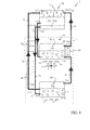
- Figures 1 to 7 illustrate a first embodiment of an apparatus
- Figure 8 illustrates the operation of an apparatus.
- the absorber fluid is designated by the letter A, the refrigerant by the letter R and the inert fluid (or pressure equalizing fluid) by the letter I.
- the liquid state is designated by the letter 1 and the gas state by the letter g (it is to be understood that "gas” is used to distinguish from liquid state and comprises vapor state, i.e. a liquid that has just undergone phase change).
- A-l designates liquid absorber and (R+I)-g a mixture of refrigerant and inert fluids in the gas state. Practically all the flows in the apparatus are mixtures of two fluids with low or high concentrations, but to simplify the description, only high concentration mixtures are explicitly mentioned as such.
- A-l is liquid absorbant which may have a low concentration of inert absorbed
- (A+I)-l is a liquid absorbant which may have a high concentration of inert absorbed.
- Figures 1 to 7 illustrate a first embodiment of an apparatus 1.
- Figure 1 is a front view of the apparatus,
- Figure 2 illustrates details of the generator,
- Figure 5 details of the absorber- condenser and
- the apparatus 1 comprises a tight enclosure 2 enclosing electric devices, such as an electrical cabinet or a component space.
- Tight refers in this context to an enclosure 2 which restricts air from flowing between the inside and outside of the enclosure, though in practical implementations some leakage may occur.
- the electric components within this hermetic enclosure 2 are cooled as explained below. It should, however, be observed that a tight enclosure is not necessary in all embodiments.
- One alternative instead of having a tight enclosure is, for instance, to have two separate airflows that do not mix together. The first air flow may pass heat towards the evaporator, for instance, while the other separate airflow passes heat away from the condenser-absorber, for instance.
- a cooling element referred to as a generator 3 is arranged with a lower part within the enclosure 2 and with an upper part outside of the enclosure.
- the generator 3 includes a plurality of tubes 4 which are divided by longitudinal internal walls into a plurality of channels.
- One alternative is to manufacture the tubes of the generator of multiport extruded tubes (MPE tubes). Such tubes may be manufactured by extruding aluminum, for instance.
- the generator 3, which is illustrated in more detail in Figure 2 is at its lower end provided with a baseplate 5.
- a baseplate 5 may be manufactured of aluminum, for instance.
- Electric components 6 which during use produce large amounts of heat are attached to the baseplate 5 and thermally connected to the baseplate 5 for conducting heat from the electric components 6 via the baseplate 5 to fluid in the tubes 4.
- the electric components 6 may be high power electronic components of a motor drive used for supplying an electric motor with electricity, for instance.
- the baseplate 5 is provided with parallel grooves into which the tubes 4 partly penetrate. Some of the longitudinal channels of the MPE tubes are therefore embedded into the baseplate 5.
- the tubes 4 are connected to a first manifold 7.
- This manifold may be implemented as a tube providing a fluid path between each of the channels in the tubes 4.
- a reservoir 8 is provided as a second tube, which is in fluid communication with the manifold 7 and located lower than the manifold 7.
- vapour generator gas is generated inside the section of the tubes 4 that penetrate into the baseplate 5 due to the heat dissipated by the electric components 6, such as power modules.
- the internal longitudinal channels of the tubes 4 are capillary sized channels.
- capillary sized refers to channels that have a size small enough for bubbles to grow uniquely in a longitudinal direction (in other words in the longitudinal direction of the channel as opposed to the radial direction) and thereby create a so called bubble lift effect by pushing the liquid upwards.
- the diameter of a channel or tube which is considered capillary depends on the fluid or refrigerant that is used (boiling) inside.
- D (sigma/(g*(rhol-rhov))) ⁇ 0.5, wherein sigma is the surface tension, g the acceleration of gravity, rhov the gas density and rhol the liquid density.
- sigma is the surface tension
- g acceleration of gravity
- rhov gas density
- rhol liquid density
- the internal diameter of such capillary channels is around 1.5 mm. Therefore bubbles will grow along the channels direction towards the lowest pressure point only and therefore push liquid up to the top of the tubes 4 into the manifold 7.
- a separator reservoir the manifold 7 and the reservoir 8 have one or more fluid connections and therefore act as a vapour-liquid separator and reservoir due to gravity and the mutual location of the manifold and reservoir.
- the apparatus 1 of Figure 1 also includes an evaporator 10, which is illustrated in more detail in Figures 3 and 4 .
- the evaporator 10 is composed of an air heat exchanger with tubes 11 attached to a bottom manifold 12 (implemented as a tube) and a top manifold 13 (implemented as a tube).
- the tubes 11 are MPE tubes with longitudinal intermediate walls that divide the tubes into a plurality of channels. Air fins 16 are brazed between the parallel tubes 11.
- An inert gas I-g is injected into a liquid refrigerant R-l with a diffuser tube inserted into the bottom manifold 12, for instance.
- the evaporated mixture of refrigerant and inert is collected into the top manifold 13.
- the evaporator 10 can be made of MPE tubes, but this is not necessary.
- the evaporator 10 provides cooling to secondary electric components 14 arranged inside the tight enclosure 2. These secondary electric components 14 are thermally connected to the evaporator 10.
- the thermal connection is obtained by an air stream 15 passing via the electric components 14 to the fins 16 of the evaporator 10, such that the fins 16 conduct heat from the air stream 15 to fluid in the tubes 11.
- a fan 17 generating the air stream 15 may be utilized.
- the electric components 14 may be capacitors and PCBs (Printed Circuit Board) which during use typically generate a relatively low amount of heat, but which require an efficient cooling in order to avoid problems due to a temperature raise.
- the power of the second components 14 may be 5 to 10 times lower than the power of the electric components 6 components.
- the apparatus 1 of Figure 1 comprises an absorber-condenser 20, shown in more detail in Figure 5 .
- the absorber-condenser 20 is installed outside of the tight enclosure 2.
- the illustrated absorber-condenser 20 is composed of an air heat exchanger with tubes 21 attached to a bottom manifold 22, which may be implemented as a tube, and a top manifold 23, which also may be implemented as a tube.
- fins 24 are arranged between the tubes 21 by brazing, for instance.
- a second fan (not illustrated) may be arranged outside of the enclosure 2 to generate an airflow passing between the tubes 21 of the absorber-condenser 20.
- the absorber-condenser 20 may be manufactured of aluminum, for instance, by a plate and bar heat exchanger technology, for instance.
- the absorber-condenser 20 preferably respects the following constraints:
- the flow length of the channels provided by the tubes 21, and therefore the height of the absorber-condenser should be high enough to allow complete absorption of the inert gas I-g into the absorber in a liquid state A-l and of the refrigerant received in a gas state R-g in to a liquid state R-l.
- This height can be determined with classical heat and mass transfer correlations.
- the cold weak absorber in a liquid state A-l coming from the solution heat exchanger 30 is allowed to shower evenly the refrigerant+inert gas mixture (R+l)-g entering the top manifold 23. Therefore the top manifold 23 may be designed for this purpose, with a porous plate inserted in the middle for example.
- the different fluids have a contact area as large as possible. Therefore the diameter of the fluid channels provided by the tubes 21 is large enough to avoid the formation of gas slugs and liquid plugs (typically a few times the capillary dimension) because these would keep the gas and liquid spatially separated and hinder the absorption process.
- the liquid pure refrigerant R-l and the liquid strong solution of absorbant+inert (A+I)-l are harvested in the bottom manifold 22.
- these two fluids are immiscible and of different densities, they will separate naturally by gravity (illustrated in Figure 8 ).
- the size and design of the bottom manifold 22 allows this natural separation to occur.
- a commercial liquid-liquid separator (not illustrated in the Figures) may be installed below the bottom manifold 22.
- the apparatus of Figure 1 also comprises a solution heat exchanger 30 that can be a standard commercial tube-in-tube heat exchanger as shown in more details in Figures 6 and 7 , and where the liquid strong absorber line 31 (containing the mixture of absorber and inert in a liquid state (A+I)-l) pre-cools the liquid weak absorber line 32 (containing the absorber in a liquid state A-l).
- the solution heat exchanger 30 representation is simplified and shown as two tubes 31 and 32 running side by side. Although this configuration would allow heat exchange, the tube-in-tube commercial solution is much more efficient because it has a larger heat transfer area.
- the apparatus of Figure 1 also includes a gas heat exchanger 40 that can be a standard commercial tube-in-tube heat exchanger, similar as the solution heat exchanger 30 illustrated in Figures 6 and 7 .
- a line 41 with inert in gas state I-g extends from the top manifold 7 of the generator 3 to the bottom manifold 12 of the evaporator 10 through the gas heat exchanger 40.
- a line 32 with the liquid weak absorber A-l extends from the liquid reservoir 8 of the generator 3 to the top manifold 23 of the absorber-condenser 20 through the solution heat exchanger 30.
- a line 31 with a liquid strong absorber (A+I)-l extends from the bottom manifold of the absorber-condenser 22 to the bottom manifold 9 of the generator 3 through the solution heat exchanger 30.
- the line 43 with the liquid refrigerant R-l extends from the bottom manifold 22 of the absorber-condenser 20 to the bottom manifold 12 of the evaporator 10 and optionally through the gas heat exchanger 40.
- Line 43 should exit from the manifold 22 of the absorber-condenser 20 above the level of liquid strong solution of absorbant+inert (A+I)-l exiting via line 31(as shown in Figure 8 ). In this way adequate separation is obtained due to gravity.
- a line 42 with a gas refrigerant+inert mixture in a gas state (R+I)-g extends from the top manifold 13 of the evaporator 10 to the top manifold 23 of the absorber-condenser 23 through the gas heat exchanger 40.
- the tubes 4 which may be MPE tubes of aluminum, for instance, extend out of the enclosure to a higher altitude than the top of the absorber-condense 20. This ensures efficient circulation within the apparatus.
- Figure 8 illustrates the operation of the apparatus.
- the apparatus illustrated in Figures 1 to 7 may operate as explained in the following.
- the absorber A and inert I should have a large boiling temperature difference to allow a good separation of the absorber A and inert I fluid in the generator.
- the saturation temperature of the refrigerant R at the system pressure must be greater than the saturation temperature of the inert I at the system pressure.
- the inert I should be strongly absorbed by the absorber A at the system pressure and at the saturation temperature of the refrigerant R.
- the refrigerant R should be nearly immiscible with the absorber A and inert I fluid mixture.
- the three fluids may not chemically react with each other or with other materials present in the apparatus, which may be manufactured of aluminum, for instance.
- the absorber A fluid should have a high saturation temperature at the system pressure.
- the refrigerant R and inert I mixture should be able to form an azeotrope in the evaporator temperature so that there is no temperature glide during the evaporation, which would improve the coefficient of performance.
- the apparatus illustrated in Figure 8 has six heat exchangers circulating three fluids, as explained above.
- the terms “weak” and “strong” are used to refer to the amount of inert gas in the mixture.
- a pre-heated strong liquid solution of inert and absorber (A+I)-l enters the generator 3 from the solution heat exchanger 30 via line 31.
- This liquid solution is vaporized by the heat load Qg from the electric components 6 and produces a strong gas mixture of inert I-g and absorber and a weak liquid solution of inert and absorber A-l.
- the upper end of the generator 3, which may be provided with tubes 4 (having capillary dimensions) partly extending out of the enclosure 2 (as illustrated in Figure 1 ) works as a bubble pump starting from the generator tank (bottom manifold 9 of the generator 3).
- the bubble pump 4 sends the absorber in a liquid state A-l to the solution heat exchanger 30 via line 32, due to the growth of spatially confined bubbles created in the bubble pump due to the capillary size of the pipes 4 and the heat load Qb.
- the solution heat exchanger 30 pre-cools the weak liquid solution of the absorber A-l sent by the bubble pump with the strong liquid solution of inert and absorber (A+I)-l coming out of the absorber-condenser 20 via line 31.
- This pre-cooling increases the capacity of the absorber liquid A-l to absorb more inert I-g in the absorber-condenser 20 and therefore improves the effectiveness of the cycle.
- the weak solution A-l can be further pre-cooled with the outside air before it enters the absorber-condenser 20.
- the inert gas line 41 passes the strong gas mixture of the inert gas I-g to the gas heat exchanger 40 from the generator 3.
- the gas heat exchanger 40 precools the inert gas I-g (which at this point ideally consists to 100% of inert gas, but in praxis may contain some absorber gas) with the strong inert and refrigerant gas mixture (R+I)-g coming out from the evaporator 10. Due to this pre-cooling refrigeration may occur in the evaporator.
- the absorber-condenser 20 which is located outside of the enclosure 2, has a double function: firstly it receives the pre-heated strong inert and refrigerant gas mixture (R+I)-g coming out from the gas heat exchanger 40 via line 42 and showers it with the pre-cooled weak absorber liquid A-l coming out from the solution heat exchanger 30 in order to absorb the inert gas I-g into the absorber A-l, thus forming a strong liquid solution of inert (A+I)-l at the exit of the absorber-condenser 20 (line 31). Secondly it condenses the refrigerant into liquid R-l above atmospheric air temperature, which is possible since the partial pressure of the refrigerant without the inert is high.
- the evaporator 10 receives liquid refrigerant R-l from the absorber-condenser 20 via line 43.
- the liquid refrigerant may optionally (not illustrated in the drawings) be precooled in a gas heat exchanger. Additionally, the evaporator 10 receives via line 41 pre-cooled strong gas mixture of inert I-g from the generator 3 via the gas heat exchanger 40.
- the inert in the gas state I-g reduces a partial pressure of the liquid refrigerant R-l and therefore also the temperature required for evaporating the liquid refrigerant R-l.
- condensation temperature will be significantly higher than the cooling air temperature (at least 10 K higher).
- a certain concentration of refrigerant mixed with inert gas exists so that this mixture will evaporate at a significantly lower temperature than that of the enclosure to be cooled (at least 10 K lower). This concentration should be ideally around 50% to minimize flow rates. However it can vary from 10% to 90% typically.
- the difference between the condensation and the evaporation temperature is called the temperature lift and indicates how much below ambient you can hope to refrigerate the enclosure containing the electronic equipment.
- DMEU Dimethylol-ethylene-urea
- DMAC Dimethylacetamide
- DMEDEG Dimethylether diethylene glycol
- DMETEG DiMethyl Ether Tetra Ethylene Glycol
- DMETrEG Dimethylether Triethylene Glycol
Landscapes
- Engineering & Computer Science (AREA)
- Thermal Sciences (AREA)
- Physics & Mathematics (AREA)
- Microelectronics & Electronic Packaging (AREA)
- Chemical & Material Sciences (AREA)
- General Engineering & Computer Science (AREA)
- Mechanical Engineering (AREA)
- Combustion & Propulsion (AREA)
- Chemical Kinetics & Catalysis (AREA)
- Materials Engineering (AREA)
- Organic Chemistry (AREA)
- Cooling Or The Like Of Electrical Apparatus (AREA)
- Sorption Type Refrigeration Machines (AREA)
Abstract
Description
- This invention relates to a solution for cooling electric components of an electric apparatus.
- Conventional refrigeration systems are dual pressure cycles where the saturation temperature difference between a condenser and an evaporator is produced by a system pressure difference. This requires a mechanical input to drive the compressor or pump for generating the change in pressure.
- A drawback with such a prior art system is the need for an mechanical input to drive a compressor or pump.
- Previously there also exists solutions utilizing a generator, an evaporator and an absorber-condenser manufactured of steel and circulating three different working fluids without the need for an mechanical input, compressor or pump. A problem with this known solution is low efficiency and high manufacturing costs.
- An object of the present invention is to solve the above mentioned drawback and to provide a novel apparatus which provides more efficient cooling of electric components and a method for selecting working fluids for a cooling system. This and other objects are achieved with the apparatus of
independent claim 1 and the method ofindependent claim 12. - In the following the present invention will be described in closer detail by way of example and with reference to the attached drawings, in which
-
Figures 1 to 7 illustrate a first embodiment of an apparatus, and -
Figure 8 illustrates the operation of an apparatus. - In the following the absorber fluid is designated by the letter A, the refrigerant by the letter R and the inert fluid (or pressure equalizing fluid) by the letter I. The liquid state is designated by the
letter 1 and the gas state by the letter g (it is to be understood that "gas" is used to distinguish from liquid state and comprises vapor state, i.e. a liquid that has just undergone phase change). Thus, for example A-l designates liquid absorber and (R+I)-g a mixture of refrigerant and inert fluids in the gas state. Practically all the flows in the apparatus are mixtures of two fluids with low or high concentrations, but to simplify the description, only high concentration mixtures are explicitly mentioned as such. Thus it is to be understood that A-l is liquid absorbant which may have a low concentration of inert absorbed, while (A+I)-l is a liquid absorbant which may have a high concentration of inert absorbed. -
Figures 1 to 7 illustrate a first embodiment of anapparatus 1.Figure 1 is a front view of the apparatus,Figure 2 illustrates details of the generator,Figures 3 and 4 details of the evaporator,Figure 5 details of the absorber- condenser andFigures 6 and 7 of the solution heat exchanger. - The
apparatus 1 comprises atight enclosure 2 enclosing electric devices, such as an electrical cabinet or a component space. Tight refers in this context to anenclosure 2 which restricts air from flowing between the inside and outside of the enclosure, though in practical implementations some leakage may occur. The electric components within thishermetic enclosure 2 are cooled as explained below. It should, however, be observed that a tight enclosure is not necessary in all embodiments. One alternative instead of having a tight enclosure is, for instance, to have two separate airflows that do not mix together. The first air flow may pass heat towards the evaporator, for instance, while the other separate airflow passes heat away from the condenser-absorber, for instance. - A cooling element referred to as a
generator 3 is arranged with a lower part within theenclosure 2 and with an upper part outside of the enclosure. Thegenerator 3 includes a plurality oftubes 4 which are divided by longitudinal internal walls into a plurality of channels. One alternative is to manufacture the tubes of the generator of multiport extruded tubes (MPE tubes). Such tubes may be manufactured by extruding aluminum, for instance. - The
generator 3, which is illustrated in more detail inFigure 2 , is at its lower end provided with abaseplate 5. Such abaseplate 5 may be manufactured of aluminum, for instance.Electric components 6 which during use produce large amounts of heat are attached to thebaseplate 5 and thermally connected to thebaseplate 5 for conducting heat from theelectric components 6 via thebaseplate 5 to fluid in thetubes 4. Theelectric components 6 may be high power electronic components of a motor drive used for supplying an electric motor with electricity, for instance. - The
baseplate 5 is provided with parallel grooves into which thetubes 4 partly penetrate. Some of the longitudinal channels of the MPE tubes are therefore embedded into thebaseplate 5. - At the upper end of the
generator 3, thetubes 4 are connected to afirst manifold 7. This manifold may be implemented as a tube providing a fluid path between each of the channels in thetubes 4. Areservoir 8 is provided as a second tube, which is in fluid communication with themanifold 7 and located lower than themanifold 7. Thereby liquid and gas exiting the channels of thetubes 4 at the upper ends of the tubes are separated by gravity. The liquid flows downwards by gravity and accumulates into thereservoir 8 while the gas remains inmanifold 7. - From
Figures 1 and2 one can observe that thetubes 4 are curved. The reason for this curvature is to ensure that the liquid will accumulate into theliquid reservoir 8 by gravity. Therefore thisgenerator 3 manufactured of curved multiport extruded tubes inFigures 1 and2 fulfills three different functions: - - A vapour generator: gas is generated inside the section of the
tubes 4 that penetrate into thebaseplate 5 due to the heat dissipated by theelectric components 6, such as power modules. - - A bubble pump: The internal longitudinal channels of the
tubes 4 are capillary sized channels. In this context "capillary sized" refers to channels that have a size small enough for bubbles to grow uniquely in a longitudinal direction (in other words in the longitudinal direction of the channel as opposed to the radial direction) and thereby create a so called bubble lift effect by pushing the liquid upwards. The diameter of a channel or tube which is considered capillary depends on the fluid or refrigerant that is used (boiling) inside. The following formula, for instance, can be used to evaluate a suitable diameter: D = (sigma/(g*(rhol-rhov)))^0.5, wherein sigma is the surface tension, g the acceleration of gravity, rhov the gas density and rhol the liquid density. Typically the internal diameter of such capillary channels is around 1.5 mm. Therefore bubbles will grow along the channels direction towards the lowest pressure point only and therefore push liquid up to the top of thetubes 4 into themanifold 7. - - A separator reservoir: the
manifold 7 and thereservoir 8 have one or more fluid connections and therefore act as a vapour-liquid separator and reservoir due to gravity and the mutual location of the manifold and reservoir. - The
apparatus 1 ofFigure 1 also includes anevaporator 10, which is illustrated in more detail inFigures 3 and 4 . Theevaporator 10 is composed of an air heat exchanger withtubes 11 attached to a bottom manifold 12 (implemented as a tube) and a top manifold 13 (implemented as a tube). - In the illustrated example the
tubes 11 are MPE tubes with longitudinal intermediate walls that divide the tubes into a plurality of channels.Air fins 16 are brazed between theparallel tubes 11. - An inert gas I-g is injected into a liquid refrigerant R-l with a diffuser tube inserted into the
bottom manifold 12, for instance. The evaporated mixture of refrigerant and inert is collected into thetop manifold 13. Theevaporator 10 can be made of MPE tubes, but this is not necessary. - The
evaporator 10 provides cooling to secondaryelectric components 14 arranged inside thetight enclosure 2. These secondaryelectric components 14 are thermally connected to theevaporator 10. One alternative is that the thermal connection is obtained by an air stream 15 passing via theelectric components 14 to thefins 16 of theevaporator 10, such that thefins 16 conduct heat from the air stream 15 to fluid in thetubes 11. In order to provide an efficient air circulation within theenclosure 2, afan 17 generating the air stream 15 may be utilized. Theelectric components 14 may be capacitors and PCBs (Printed Circuit Board) which during use typically generate a relatively low amount of heat, but which require an efficient cooling in order to avoid problems due to a temperature raise. Typically the power of thesecond components 14 may be 5 to 10 times lower than the power of theelectric components 6 components. - The
apparatus 1 ofFigure 1 comprises an absorber-condenser 20, shown in more detail inFigure 5 . The absorber-condenser 20 is installed outside of thetight enclosure 2. The illustrated absorber-condenser 20 is composed of an air heat exchanger withtubes 21 attached to abottom manifold 22, which may be implemented as a tube, and atop manifold 23, which also may be implemented as a tube. In order to enhance transfer of heat between the absorber-condenser 20 and the surrounding air,fins 24 are arranged between thetubes 21 by brazing, for instance. Additionally, a second fan (not illustrated) may be arranged outside of theenclosure 2 to generate an airflow passing between thetubes 21 of the absorber-condenser 20. - The absorber-
condenser 20 may be manufactured of aluminum, for instance, by a plate and bar heat exchanger technology, for instance. The absorber-condenser 20 preferably respects the following constraints: - a) the flow length of the channels provided by the
tubes 21, and therefore the height of the absorber-condenser, should be high enough to allow complete absorption of the inert gas I-g into the absorber in a liquid state A-l and of the refrigerant received in a gas state R-g in to a liquid state R-l. This height can be determined with classical heat and mass transfer correlations. - b) the cold weak absorber in a liquid state A-l coming from the
solution heat exchanger 30 is allowed to shower evenly the refrigerant+inert gas mixture (R+l)-g entering thetop manifold 23. Therefore thetop manifold 23 may be designed for this purpose, with a porous plate inserted in the middle for example. - c) during the absorption and condensation processes, which take place together, the different fluids have a contact area as large as possible. Therefore the diameter of the fluid channels provided by the
tubes 21 is large enough to avoid the formation of gas slugs and liquid plugs (typically a few times the capillary dimension) because these would keep the gas and liquid spatially separated and hinder the absorption process. - d) the liquid pure refrigerant R-l and the liquid strong solution of absorbant+inert (A+I)-l are harvested in the
bottom manifold 22. As these two fluids are immiscible and of different densities, they will separate naturally by gravity (illustrated inFigure 8 ). The size and design of thebottom manifold 22 allows this natural separation to occur. Alternatively a commercial liquid-liquid separator (not illustrated in the Figures) may be installed below thebottom manifold 22. - The apparatus of
Figure 1 also comprises asolution heat exchanger 30 that can be a standard commercial tube-in-tube heat exchanger as shown in more details inFigures 6 and 7 , and where the liquid strong absorber line 31 (containing the mixture of absorber and inert in a liquid state (A+I)-l) pre-cools the liquid weak absorber line 32 (containing the absorber in a liquid state A-l). It should be observed that inFigure 1 thesolution heat exchanger 30 representation is simplified and shown as twotubes - The apparatus of
Figure 1 also includes agas heat exchanger 40 that can be a standard commercial tube-in-tube heat exchanger, similar as thesolution heat exchanger 30 illustrated inFigures 6 and 7 . - It should be observed that in
Figure 1 heat transfer occurs only between theline 41 with inert in the gas state I-g and theline 42 with a mixture of refrigerant and inert (R+I)-g, both in a gas state. However, as an alternative it is possible to haveline 42 with a mixture of refrigerant and inert (R+I)-g to pre-cool bothline 41 with inert in gas state I-g andline 43 with the refrigerant in a liquid state R-l before they enter theevaporator 10. This can be achieved by installing two tube-in-tube heat exchangers 40 in series, for instance. - A
line 41 with inert in gas state I-g extends from thetop manifold 7 of thegenerator 3 to thebottom manifold 12 of theevaporator 10 through thegas heat exchanger 40. Aline 32 with the liquid weak absorber A-l extends from theliquid reservoir 8 of thegenerator 3 to thetop manifold 23 of the absorber-condenser 20 through thesolution heat exchanger 30. Aline 31 with a liquid strong absorber (A+I)-l extends from the bottom manifold of the absorber-condenser 22 to thebottom manifold 9 of thegenerator 3 through thesolution heat exchanger 30. - The
line 43 with the liquid refrigerant R-l extends from thebottom manifold 22 of the absorber-condenser 20 to thebottom manifold 12 of theevaporator 10 and optionally through thegas heat exchanger 40.Line 43 should exit from themanifold 22 of the absorber-condenser 20 above the level of liquid strong solution of absorbant+inert (A+I)-l exiting via line 31(as shown inFigure 8 ). In this way adequate separation is obtained due to gravity. - A
line 42 with a gas refrigerant+inert mixture in a gas state (R+I)-g extends from thetop manifold 13 of theevaporator 10 to thetop manifold 23 of the absorber-condenser 23 through thegas heat exchanger 40. - As most clearly illustrated in
Figure 1 , thetubes 4, which may be MPE tubes of aluminum, for instance, extend out of the enclosure to a higher altitude than the top of the absorber-condense 20. This ensures efficient circulation within the apparatus. -
Figure 8 illustrates the operation of the apparatus. The apparatus illustrated inFigures 1 to 7 may operate as explained in the following. - Three different fluids are circulated in the
apparatus 1, an absorber A, a refrigerant R and an inert I (which also is called a pressure equalizing gas). The absorber A and inert I should have a large boiling temperature difference to allow a good separation of the absorber A and inert I fluid in the generator. The saturation temperature of the refrigerant R at the system pressure must be greater than the saturation temperature of the inert I at the system pressure. The inert I should be strongly absorbed by the absorber A at the system pressure and at the saturation temperature of the refrigerant R. The refrigerant R should be nearly immiscible with the absorber A and inert I fluid mixture. The three fluids may not chemically react with each other or with other materials present in the apparatus, which may be manufactured of aluminum, for instance. The absorber A fluid should have a high saturation temperature at the system pressure. Ideally the refrigerant R and inert I mixture should be able to form an azeotrope in the evaporator temperature so that there is no temperature glide during the evaporation, which would improve the coefficient of performance. - The apparatus illustrated in
Figure 8 has six heat exchangers circulating three fluids, as explained above. The terms "weak" and "strong" are used to refer to the amount of inert gas in the mixture. - A pre-heated strong liquid solution of inert and absorber (A+I)-l enters the
generator 3 from thesolution heat exchanger 30 vialine 31. This liquid solution is vaporized by the heat load Qg from theelectric components 6 and produces a strong gas mixture of inert I-g and absorber and a weak liquid solution of inert and absorber A-l. - The upper end of the
generator 3, which may be provided with tubes 4 (having capillary dimensions) partly extending out of the enclosure 2 (as illustrated inFigure 1 ) works as a bubble pump starting from the generator tank (bottom manifold 9 of the generator 3). Thebubble pump 4 sends the absorber in a liquid state A-l to thesolution heat exchanger 30 vialine 32, due to the growth of spatially confined bubbles created in the bubble pump due to the capillary size of thepipes 4 and the heat load Qb. Thesolution heat exchanger 30 pre-cools the weak liquid solution of the absorber A-l sent by the bubble pump with the strong liquid solution of inert and absorber (A+I)-l coming out of the absorber-condenser 20 vialine 31. This pre-cooling increases the capacity of the absorber liquid A-l to absorb more inert I-g in the absorber-condenser 20 and therefore improves the effectiveness of the cycle. Optionally the weak solution A-l can be further pre-cooled with the outside air before it enters the absorber-condenser 20. - The
inert gas line 41 passes the strong gas mixture of the inert gas I-g to thegas heat exchanger 40 from thegenerator 3. Thegas heat exchanger 40 precools the inert gas I-g (which at this point ideally consists to 100% of inert gas, but in praxis may contain some absorber gas) with the strong inert and refrigerant gas mixture (R+I)-g coming out from theevaporator 10. Due to this pre-cooling refrigeration may occur in the evaporator. - The absorber-
condenser 20, which is located outside of theenclosure 2, has a double function: firstly it receives the pre-heated strong inert and refrigerant gas mixture (R+I)-g coming out from thegas heat exchanger 40 vialine 42 and showers it with the pre-cooled weak absorber liquid A-l coming out from thesolution heat exchanger 30 in order to absorb the inert gas I-g into the absorber A-l, thus forming a strong liquid solution of inert (A+I)-l at the exit of the absorber-condenser 20 (line 31). Secondly it condenses the refrigerant into liquid R-l above atmospheric air temperature, which is possible since the partial pressure of the refrigerant without the inert is high. Then the two non-miscible liquids R-l and (A+I)-l are separated at thebottom manifold 22 of the absorber-condenser 20 by gravity. Both the absorption and condensation are exothermic phenomena and reject a total heat load (Qc+Qa) into the surroundings outside of theenclosure 2. Qa is the absorption heat and Qc is the condensation heat. - The
evaporator 10 receives liquid refrigerant R-l from the absorber-condenser 20 vialine 43. The liquid refrigerant may optionally (not illustrated in the drawings) be precooled in a gas heat exchanger. Additionally, theevaporator 10 receives vialine 41 pre-cooled strong gas mixture of inert I-g from thegenerator 3 via thegas heat exchanger 40. The inert in the gas state I-g reduces a partial pressure of the liquid refrigerant R-l and therefore also the temperature required for evaporating the liquid refrigerant R-l. The relatively low heat load Qe from theelectric components 14 attached to theevaporator 10 or arranged inside the enclosure where they are thermally connected to the evaporator via air (and possibly afan 17 generating an airflow), is therefore sufficient in the presence of inert gas I-g to evaporate the liquid refrigerant R-l. Evaporation can therefore be achieved a relatively low temperature Te. This phenomena is endothermic and absorbs a heat load Qe from inside of thetight enclosure 2. - Attention should be paid to the selection of the fluids utilized in the apparatus. In order to be able to utilize heat exchangers manufactured of materials that efficiently conduct heat, suitable fluids needs to be selected. Preferably, it is possible to utilize aluminum in the heat exchangers, as aluminum has good heat conducting properties (as compared to steel for instance) and as heat exchangers of aluminum are relatively easy to manufacture by extrusion and/or a combination of extrusion and soldering, for instance. Furthermore they are compact and low cost.
- Generally speaking the process for selecting fluid combinations to be used in the previously described apparatus may be as follows:
- 1) Choose a refrigerant + inert combination and a working pressure so that:
- i) at 100% refrigerant the condensation temperature will be significantly higher than the cooling air temperature (at least 10 K higher).
- ii) a certain concentration of refrigerant mixed with inert gas exists so that this mixture will evaporate at a significantly lower temperature than that of the enclosure to be cooled (at least 10 K lower). This concentration should be ideally around 50% to minimize flow rates. However it can vary from 10% to 90% typically.
- iii) the difference between the condensation and the evaporation temperature is called the temperature lift and indicates how much below ambient you can hope to refrigerate the enclosure containing the electronic equipment.
- 2) Choose an absorber fluid so that at the working pressure determined by the refrigerant + inert combination and at the absorption temperature (that is equal to the condensation temperature since the two phenomena take place in the same heat exchanger), the concentration of inert gas in the absorber is as high as possible. This will ensure that the generator exit temperature is as low as possible (and therefore the semiconductor operating temperature is low) and that the concentration of absorber in the vaporized inert gas is as low as possible (which improves the coefficient of performance since this absorber gas does not play any refrigeration role in the evaporator).
- For the described apparatus utilizing aluminum in the heat exchangers excellent fluid combinations may be achieved with the following fluid combinations:
- - as the inert fluid R134a (1,1,1,2-Tetrafluoroethane) in combination with butane as the refrigerant fluid, or
- - as the inert fluid R32 (Difluoromethane) in combination with cyclopropane as the refrigerant fluid.
- With the above two alternatives, possible absorbers are:
- - alkyl acetamides, linear and cyclic, such as DMEU (Dimethylol-ethylene-urea) or DMAC (Dimethylacetamide)
- - carbonate esters, such as DMC (Dimethyl carbonate)
- - glycol ethers, such as DMEDEG (Dimethylether diethylene glycol), DMETEG (DiMethyl Ether Tetra Ethylene Glycol), DMETrEG (Dimethylether Triethylene Glycol).
- The use of the novel combination of inert, refrigerant and absorber as working fluids in the apparatus makes it possible to manufacture the components of the apparatus of a material which is very well suitable for use in a cooling device, in other words aluminum. This also simplifies the manufacturing of the apparatus.
- It is to be understood that the above description and the accompanying figures are only intended to illustrate the present invention. It will be obvious to a person skilled in the art that the invention can be varied and modified without departing from the scope of the invention.
Claims (12)
- An apparatus (1) comprising a generator (3), an evaporator (10) and an absorber-condenser (20) circulating an absorber, an inert and a refrigerant, characterized in that
the generator (3) is arranged to receive a heat load (Qg) from first electric components (6), the generator (3) comprising a fluid channel for receiving fluid including a mixture of the absorber and the inert, and to evaporate a part of the received fluid with the heat load (Qg) from the first electric components (6),
the evaporator (10) is arranged to receive a heat load (Qe) from second electric components (14), the evaporator (10) comprises a fluid channel including a mixture of the inert and the refrigerant for transferring heat (Qe) received from the second electric components (14) into the fluid in the fluid channel,
the absorber-condenser (20) is arranged to receive heated absorber from the generator (3) and heated inert and refrigerant from the evaporator (10), and to transfer heat (Qc+Qa) from the received fluids to surroundings, and
one or more of the generator (3), evaporator (10) and absorber-condenser (20) is entirely or partly manufactured of aluminum. - The apparatus according to claim 1, characterized in that the apparatus comprises a tight enclosure (2) enclosing the generator (3) and the evaporator (3), and the absorber-condenser (20) is arranged outside of the tight enclosure for transferring heat (Qc+Qa) to the outside of the tight enclosure.
- The apparatus according to claim 1 or 2, characterized in that the inert and refrigerant are selected such that R134a is used as the inert and butane as the refrigerant fluid, or R32 is used as the inert and cyclopropane is used as the refrigerant, and
the absorber is selected to include an alkyl acetamide, a carbonate ester or a glycol ester. - The apparatus according to one of claims 1 to 3, characterized in that the fluid channel of the evaporator (10) is arranged to receive the refrigerant in a liquid state (R-l) and the inert in a gas (I-g) state, whereby the inert in the gas state (I-g) reduces a partial pressure of the refrigerant in a liquid (R-l) state and the temperature required for evaporating the refrigerant in the liquid state, such that the refrigerant in the liquid state is evaporated.
- The apparatus according to one of claims 1 to 4, characterized in that an operating temperature of the second electric components (14) is lower than an operating temperature of the first electric components (6).
- The apparatus according to one of claims 1 to 5, characterized in that the first electric components (6) include high power electronic devices, and the second electric components (14) include passive electric components.
- The apparatus according to one of claims 1 to 6, characterized in that
the fluid channel of the generator (3) is arranged to heat the received fluids with heat (Qg) received from the first electric components (6), to provide the absorber-condenser (20) with the absorber in a liquid state (A-l), and to provide the fluid channel of the evaporator (10) with the vaporized inert in a gas state (I-g),
the fluid channel of the evaporator (10) is arranged to receive the vaporized inert in a gas state (I-g) from the generator (3) and to receive the refrigerant in a liquid state (R-l), to heat the received fluids with heat (Qe) from the second electric components (14) and to provide the absorber-condenser (20) with the vaporized inert and vaporized refrigerant as a gas mixture ((R+I)-g), and
the absorber-condenser (20) is arranged to receive the absorber in a liquid state (A-l) from the generator and the vaporized inert and vaporized refrigerant as a gas mixture ((R+I)-g) from the evaporator (10), to absorb the vaporized inert (I-g) by the absorber in a liquid state (A-l) in order to obtain a liquid of the miscible inert and absorber and to condense the refrigerant, which is sparingly miscible or not miscible with the absorber and inert, into a liquid state (R-l) while transferring heat (Qc+Qa) from the fluids to the surroundings, and to provide the generator (3) with the absorber and inert as a liquid mixture ((A+I)-l) and the evaporator (10) with the refrigerant in a liquid state (R-l). - The apparatus according to one of claims 1 to 7, characterized in that the generator (3) is provided with a bubble pump as tubes (4) which have capillary dimensions and partly extend out of a tight enclosure (2) enclosing the generator (3) and the evaporator (3), to a higher altitude than an upper part of the absorber-condenser (20) which is located outside of the tight enclosure (2), for providing the absorber-condenser (20) with the absorber in a liquid state (A-l).
- The apparatus according to claim 8, characterized in that the tubes are curved multiport extruded tubes that are divided by internal longitudinal walls into a plurality of channels, the channels of the multiport extruded tubes are provided with a manifold (7) in an upper end of the tubes (4), said manifold (7) being in a fluid connection with the evaporator (10) for providing the evaporator (10) with inert in a gas state (I-g), and with a reservoir (8) which is located lower than the manifold (7) for receiving and providing the absorber-condenser (20) with absorber in a liquid state (A-l).
- The apparatus according to one of claims 7 to 9, characterized in that the apparatus comprises a solution heat exchanger (30) for cooling the absorber provided in a liquid state (A-l) from the generator to the absorber-condenser (20) with the absorber and inert as a liquid mixture ((A+I)-l) provided by the absorber-condenser (20) to the generator (3).
- The apparatus according to one of claims 7 to 10, characterized in that the apparatus comprises a gas heat exchanger (40) for transferring heat between the inert provided in the gas state (I-g) from the generator (3) to the evaporator (10) and the vaporized inert and refrigerant in the gas mixture ((R+I)-g) provided by the evaporator (10) to the absorber-condenser (20).
- A method for selecting a combination of three different working fluids including an absorber, an inert and a refrigerant for a cooling system, characterized in that
the inert and refrigerant are selected such that R134a is used as the inert and butane as the refrigerant fluid, or R32 is used as the inert and cyclopropane is used as the refrigerant, and
the absorber is selected to include an alkyl acetamide, a carbonate ester or a glycol ester.
Priority Applications (3)
| Application Number | Priority Date | Filing Date | Title |
|---|---|---|---|
| EP13179085.9A EP2833084B1 (en) | 2013-08-02 | 2013-08-02 | Refrigeration apparatus and method |
| CN201410377056.9A CN104344596B (en) | 2013-08-02 | 2014-08-01 | Refrigeration apparatus and method |
| US14/450,917 US20150033772A1 (en) | 2013-08-02 | 2014-08-04 | Apparatus and method for cooling electric components |
Applications Claiming Priority (1)
| Application Number | Priority Date | Filing Date | Title |
|---|---|---|---|
| EP13179085.9A EP2833084B1 (en) | 2013-08-02 | 2013-08-02 | Refrigeration apparatus and method |
Publications (3)
| Publication Number | Publication Date |
|---|---|
| EP2833084A1 true EP2833084A1 (en) | 2015-02-04 |
| EP2833084A9 EP2833084A9 (en) | 2016-03-16 |
| EP2833084B1 EP2833084B1 (en) | 2016-10-12 |
Family
ID=48914135
Family Applications (1)
| Application Number | Title | Priority Date | Filing Date |
|---|---|---|---|
| EP13179085.9A Active EP2833084B1 (en) | 2013-08-02 | 2013-08-02 | Refrigeration apparatus and method |
Country Status (3)
| Country | Link |
|---|---|
| US (1) | US20150033772A1 (en) |
| EP (1) | EP2833084B1 (en) |
| CN (1) | CN104344596B (en) |
Cited By (2)
| Publication number | Priority date | Publication date | Assignee | Title |
|---|---|---|---|---|
| WO2017200551A1 (en) * | 2016-05-20 | 2017-11-23 | General Electric Company | Cooling system and methods of assembling the same |
| US10104814B2 (en) | 2014-11-03 | 2018-10-16 | General Electric Company | System and method for cooling electrical components of a power converter |
Families Citing this family (6)
| Publication number | Priority date | Publication date | Assignee | Title |
|---|---|---|---|---|
| EP2767783B1 (en) * | 2013-02-15 | 2016-07-27 | ABB Research Ltd. | A cooling apparatus |
| US9608686B1 (en) * | 2015-12-03 | 2017-03-28 | Honeywell Federal Manufacturing & Technologies, Llc | Case for cooling an electronic device via an endothermic reaction |
| WO2021194168A1 (en) * | 2020-03-23 | 2021-09-30 | 주식회사 케이엠더블유 | Heat dissipation device for electronic element |
| CN113365478A (en) * | 2021-06-22 | 2021-09-07 | 中国联合网络通信集团有限公司 | Cooling device and cluster router |
| CN115915705B (en) * | 2022-10-20 | 2025-12-12 | 华为数字能源技术有限公司 | A refrigeration system and electrical equipment |
| CN120529539A (en) * | 2024-02-21 | 2025-08-22 | 北京小米移动软件有限公司 | Temperature averaging plate, method for manufacturing temperature averaging plate, and electronic equipment |
Citations (4)
| Publication number | Priority date | Publication date | Assignee | Title |
|---|---|---|---|---|
| US3065609A (en) * | 1960-06-01 | 1962-11-27 | Sherer Gillett Company | Absorption refrigeration system |
| US3977853A (en) * | 1973-09-11 | 1976-08-31 | Sarlab Aktiengesellschaft | Refrigerator with an absorption refrigerating apparatus |
| US7394655B1 (en) * | 2005-03-07 | 2008-07-01 | O'keeffe William F | Absorptive cooling for electronic devices |
| US20090178436A1 (en) * | 2008-01-14 | 2009-07-16 | Freescale Semiconductor, Inc. | Microelectronic refrigeration system and method |
Family Cites Families (9)
| Publication number | Priority date | Publication date | Assignee | Title |
|---|---|---|---|---|
| GB282428A (en) * | 1926-12-16 | 1928-11-15 | Albert Einstein | Improvements relating to refrigerating apparatus |
| US2040894A (en) * | 1934-12-11 | 1936-05-19 | Glenn F Zellhoefer | Absorption refrigeration |
| US2384861A (en) * | 1943-04-02 | 1945-09-18 | Servel Inc | Refrigeration |
| US5367884B1 (en) * | 1991-03-12 | 1996-12-31 | Phillips Eng Co | Generator-absorber-heat exchange heat transfer apparatus and method and use thereof in a heat pump |
| CA2095494C (en) * | 1992-06-10 | 1998-08-11 | Ron C. Lee | Cooling method and apparatus |
| US20050005623A1 (en) * | 2002-11-12 | 2005-01-13 | Thermal Form & Function Llc | Pumped liquid cooling system using a phase change refrigerant |
| EP2031332B1 (en) * | 2007-08-27 | 2010-09-15 | ABB Research LTD | Heat exchanger for power-electronics components |
| US9994751B2 (en) * | 2008-04-30 | 2018-06-12 | Honeywell International Inc. | Absorption refrigeration cycles using a LGWP refrigerant |
| CN102239229A (en) * | 2008-11-07 | 2011-11-09 | 纳幕尔杜邦公司 | Absorption cycle utilizing ionic compounds and/or non-ionic absorbents as working fluids |
-
2013
- 2013-08-02 EP EP13179085.9A patent/EP2833084B1/en active Active
-
2014
- 2014-08-01 CN CN201410377056.9A patent/CN104344596B/en active Active
- 2014-08-04 US US14/450,917 patent/US20150033772A1/en not_active Abandoned
Patent Citations (4)
| Publication number | Priority date | Publication date | Assignee | Title |
|---|---|---|---|---|
| US3065609A (en) * | 1960-06-01 | 1962-11-27 | Sherer Gillett Company | Absorption refrigeration system |
| US3977853A (en) * | 1973-09-11 | 1976-08-31 | Sarlab Aktiengesellschaft | Refrigerator with an absorption refrigerating apparatus |
| US7394655B1 (en) * | 2005-03-07 | 2008-07-01 | O'keeffe William F | Absorptive cooling for electronic devices |
| US20090178436A1 (en) * | 2008-01-14 | 2009-07-16 | Freescale Semiconductor, Inc. | Microelectronic refrigeration system and method |
Non-Patent Citations (2)
| Title |
|---|
| "SELF-SUFFICIENT COOLING SYSTEM FOR ELECTRONIC COMPONENTS", IBM TECHNICAL DISCLOSURE BULLETIN,, vol. 30, no. 6, 1 November 1987 (1987-11-01), pages 389 - 390, XP001450208 * |
| ZOHAR A ET AL: "Performance of diffusion absorption refrigeration cycle with organic working fluids", INTERNATIONAL JOURNAL OF REFRIGERATION, ELSEVIER, PARIS, FR, vol. 32, no. 6, 1 September 2009 (2009-09-01), pages 1241 - 1246, XP026421668, ISSN: 0140-7007, [retrieved on 20090127] * |
Cited By (2)
| Publication number | Priority date | Publication date | Assignee | Title |
|---|---|---|---|---|
| US10104814B2 (en) | 2014-11-03 | 2018-10-16 | General Electric Company | System and method for cooling electrical components of a power converter |
| WO2017200551A1 (en) * | 2016-05-20 | 2017-11-23 | General Electric Company | Cooling system and methods of assembling the same |
Also Published As
| Publication number | Publication date |
|---|---|
| CN104344596A (en) | 2015-02-11 |
| CN104344596B (en) | 2017-04-12 |
| EP2833084B1 (en) | 2016-10-12 |
| EP2833084A9 (en) | 2016-03-16 |
| US20150033772A1 (en) | 2015-02-05 |
Similar Documents
| Publication | Publication Date | Title |
|---|---|---|
| EP2833084B1 (en) | Refrigeration apparatus and method | |
| US9763358B2 (en) | Apparatus with diffusion-absorption cycle | |
| US20070209782A1 (en) | System and method for cooling a server-based data center with sub-ambient cooling | |
| JP6554894B2 (en) | Electrical component cooling system | |
| US9958213B2 (en) | Heat exchanger | |
| EP2767783B1 (en) | A cooling apparatus | |
| US10436519B1 (en) | Cocurrent loop thermosyphon heat transfer system for sub-ambient evaporative cooling and cool storage | |
| CN102748970A (en) | Two-phase flow power heat pipe device | |
| JP2010010204A (en) | Ebullient cooling device | |
| US8978403B2 (en) | Cooling apparatus | |
| JP2015098980A (en) | Air conditioning equipment in information processing room | |
| JP2017112189A (en) | Thermosiphon cooling device | |
| CN107208980A (en) | Loop circuit heat pipe with satellite-type evaporator | |
| CN108375238B (en) | Absorption refrigerator | |
| JP6805473B2 (en) | Absorption chiller | |
| EP4196722B1 (en) | Cooling system with intermediate chamber | |
| CN119997461B (en) | Active/passive cooling system | |
| WO2004018950A1 (en) | Falling film vapor absorber, cooling system, and method | |
| JP2008232574A (en) | Absorption refrigerating machine |
Legal Events
| Date | Code | Title | Description |
|---|---|---|---|
| 17P | Request for examination filed |
Effective date: 20130802 |
|
| AK | Designated contracting states |
Kind code of ref document: A1 Designated state(s): AL AT BE BG CH CY CZ DE DK EE ES FI FR GB GR HR HU IE IS IT LI LT LU LV MC MK MT NL NO PL PT RO RS SE SI SK SM TR |
|
| AX | Request for extension of the european patent |
Extension state: BA ME |
|
| PUAI | Public reference made under article 153(3) epc to a published international application that has entered the european phase |
Free format text: ORIGINAL CODE: 0009012 |
|
| R17P | Request for examination filed (corrected) |
Effective date: 20150227 |
|
| RBV | Designated contracting states (corrected) |
Designated state(s): AL AT BE BG CH CY CZ DE DK EE ES FI FR GB GR HR HU IE IS IT LI LT LU LV MC MK MT NL NO PL PT RO RS SE SI SK SM TR |
|
| GRAP | Despatch of communication of intention to grant a patent |
Free format text: ORIGINAL CODE: EPIDOSNIGR1 |
|
| INTG | Intention to grant announced |
Effective date: 20160509 |
|
| GRAS | Grant fee paid |
Free format text: ORIGINAL CODE: EPIDOSNIGR3 |
|
| GRAA | (expected) grant |
Free format text: ORIGINAL CODE: 0009210 |
|
| AK | Designated contracting states |
Kind code of ref document: B1 Designated state(s): AL AT BE BG CH CY CZ DE DK EE ES FI FR GB GR HR HU IE IS IT LI LT LU LV MC MK MT NL NO PL PT RO RS SE SI SK SM TR |
|
| REG | Reference to a national code |
Ref country code: GB Ref legal event code: FG4D |
|
| REG | Reference to a national code |
Ref country code: CH Ref legal event code: EP |
|
| REG | Reference to a national code |
Ref country code: AT Ref legal event code: REF Ref document number: 836892 Country of ref document: AT Kind code of ref document: T Effective date: 20161015 |
|
| REG | Reference to a national code |
Ref country code: IE Ref legal event code: FG4D |
|
| REG | Reference to a national code |
Ref country code: DE Ref legal event code: R096 Ref document number: 602013012651 Country of ref document: DE |
|
| REG | Reference to a national code |
Ref country code: LT Ref legal event code: MG4D |
|
| REG | Reference to a national code |
Ref country code: NL Ref legal event code: MP Effective date: 20161012 |
|
| PG25 | Lapsed in a contracting state [announced via postgrant information from national office to epo] |
Ref country code: LV Free format text: LAPSE BECAUSE OF FAILURE TO SUBMIT A TRANSLATION OF THE DESCRIPTION OR TO PAY THE FEE WITHIN THE PRESCRIBED TIME-LIMIT Effective date: 20161012 |
|
| REG | Reference to a national code |
Ref country code: AT Ref legal event code: MK05 Ref document number: 836892 Country of ref document: AT Kind code of ref document: T Effective date: 20161012 |
|
| PG25 | Lapsed in a contracting state [announced via postgrant information from national office to epo] |
Ref country code: SE Free format text: LAPSE BECAUSE OF FAILURE TO SUBMIT A TRANSLATION OF THE DESCRIPTION OR TO PAY THE FEE WITHIN THE PRESCRIBED TIME-LIMIT Effective date: 20161012 Ref country code: NO Free format text: LAPSE BECAUSE OF FAILURE TO SUBMIT A TRANSLATION OF THE DESCRIPTION OR TO PAY THE FEE WITHIN THE PRESCRIBED TIME-LIMIT Effective date: 20170112 Ref country code: LT Free format text: LAPSE BECAUSE OF FAILURE TO SUBMIT A TRANSLATION OF THE DESCRIPTION OR TO PAY THE FEE WITHIN THE PRESCRIBED TIME-LIMIT Effective date: 20161012 Ref country code: GR Free format text: LAPSE BECAUSE OF FAILURE TO SUBMIT A TRANSLATION OF THE DESCRIPTION OR TO PAY THE FEE WITHIN THE PRESCRIBED TIME-LIMIT Effective date: 20170113 |
|
| PG25 | Lapsed in a contracting state [announced via postgrant information from national office to epo] |
Ref country code: PL Free format text: LAPSE BECAUSE OF FAILURE TO SUBMIT A TRANSLATION OF THE DESCRIPTION OR TO PAY THE FEE WITHIN THE PRESCRIBED TIME-LIMIT Effective date: 20161012 Ref country code: PT Free format text: LAPSE BECAUSE OF FAILURE TO SUBMIT A TRANSLATION OF THE DESCRIPTION OR TO PAY THE FEE WITHIN THE PRESCRIBED TIME-LIMIT Effective date: 20170213 Ref country code: HR Free format text: LAPSE BECAUSE OF FAILURE TO SUBMIT A TRANSLATION OF THE DESCRIPTION OR TO PAY THE FEE WITHIN THE PRESCRIBED TIME-LIMIT Effective date: 20161012 Ref country code: RS Free format text: LAPSE BECAUSE OF FAILURE TO SUBMIT A TRANSLATION OF THE DESCRIPTION OR TO PAY THE FEE WITHIN THE PRESCRIBED TIME-LIMIT Effective date: 20161012 Ref country code: AT Free format text: LAPSE BECAUSE OF FAILURE TO SUBMIT A TRANSLATION OF THE DESCRIPTION OR TO PAY THE FEE WITHIN THE PRESCRIBED TIME-LIMIT Effective date: 20161012 Ref country code: ES Free format text: LAPSE BECAUSE OF FAILURE TO SUBMIT A TRANSLATION OF THE DESCRIPTION OR TO PAY THE FEE WITHIN THE PRESCRIBED TIME-LIMIT Effective date: 20161012 Ref country code: BE Free format text: LAPSE BECAUSE OF FAILURE TO SUBMIT A TRANSLATION OF THE DESCRIPTION OR TO PAY THE FEE WITHIN THE PRESCRIBED TIME-LIMIT Effective date: 20161012 Ref country code: IS Free format text: LAPSE BECAUSE OF FAILURE TO SUBMIT A TRANSLATION OF THE DESCRIPTION OR TO PAY THE FEE WITHIN THE PRESCRIBED TIME-LIMIT Effective date: 20170212 Ref country code: NL Free format text: LAPSE BECAUSE OF FAILURE TO SUBMIT A TRANSLATION OF THE DESCRIPTION OR TO PAY THE FEE WITHIN THE PRESCRIBED TIME-LIMIT Effective date: 20161012 |
|
| REG | Reference to a national code |
Ref country code: DE Ref legal event code: R097 Ref document number: 602013012651 Country of ref document: DE |
|
| PG25 | Lapsed in a contracting state [announced via postgrant information from national office to epo] |
Ref country code: DK Free format text: LAPSE BECAUSE OF FAILURE TO SUBMIT A TRANSLATION OF THE DESCRIPTION OR TO PAY THE FEE WITHIN THE PRESCRIBED TIME-LIMIT Effective date: 20161012 Ref country code: SK Free format text: LAPSE BECAUSE OF FAILURE TO SUBMIT A TRANSLATION OF THE DESCRIPTION OR TO PAY THE FEE WITHIN THE PRESCRIBED TIME-LIMIT Effective date: 20161012 Ref country code: CZ Free format text: LAPSE BECAUSE OF FAILURE TO SUBMIT A TRANSLATION OF THE DESCRIPTION OR TO PAY THE FEE WITHIN THE PRESCRIBED TIME-LIMIT Effective date: 20161012 Ref country code: RO Free format text: LAPSE BECAUSE OF FAILURE TO SUBMIT A TRANSLATION OF THE DESCRIPTION OR TO PAY THE FEE WITHIN THE PRESCRIBED TIME-LIMIT Effective date: 20161012 Ref country code: EE Free format text: LAPSE BECAUSE OF FAILURE TO SUBMIT A TRANSLATION OF THE DESCRIPTION OR TO PAY THE FEE WITHIN THE PRESCRIBED TIME-LIMIT Effective date: 20161012 |
|
| PLBE | No opposition filed within time limit |
Free format text: ORIGINAL CODE: 0009261 |
|
| STAA | Information on the status of an ep patent application or granted ep patent |
Free format text: STATUS: NO OPPOSITION FILED WITHIN TIME LIMIT |
|
| REG | Reference to a national code |
Ref country code: FR Ref legal event code: PLFP Year of fee payment: 5 |
|
| PG25 | Lapsed in a contracting state [announced via postgrant information from national office to epo] |
Ref country code: SM Free format text: LAPSE BECAUSE OF FAILURE TO SUBMIT A TRANSLATION OF THE DESCRIPTION OR TO PAY THE FEE WITHIN THE PRESCRIBED TIME-LIMIT Effective date: 20161012 Ref country code: BG Free format text: LAPSE BECAUSE OF FAILURE TO SUBMIT A TRANSLATION OF THE DESCRIPTION OR TO PAY THE FEE WITHIN THE PRESCRIBED TIME-LIMIT Effective date: 20170112 |
|
| 26N | No opposition filed |
Effective date: 20170713 |
|
| PG25 | Lapsed in a contracting state [announced via postgrant information from national office to epo] |
Ref country code: SI Free format text: LAPSE BECAUSE OF FAILURE TO SUBMIT A TRANSLATION OF THE DESCRIPTION OR TO PAY THE FEE WITHIN THE PRESCRIBED TIME-LIMIT Effective date: 20161012 |
|
| REG | Reference to a national code |
Ref country code: CH Ref legal event code: PL |
|
| PG25 | Lapsed in a contracting state [announced via postgrant information from national office to epo] |
Ref country code: MC Free format text: LAPSE BECAUSE OF FAILURE TO SUBMIT A TRANSLATION OF THE DESCRIPTION OR TO PAY THE FEE WITHIN THE PRESCRIBED TIME-LIMIT Effective date: 20161012 |
|
| PG25 | Lapsed in a contracting state [announced via postgrant information from national office to epo] |
Ref country code: CH Free format text: LAPSE BECAUSE OF NON-PAYMENT OF DUE FEES Effective date: 20170831 Ref country code: LI Free format text: LAPSE BECAUSE OF NON-PAYMENT OF DUE FEES Effective date: 20170831 |
|
| REG | Reference to a national code |
Ref country code: IE Ref legal event code: MM4A |
|
| PG25 | Lapsed in a contracting state [announced via postgrant information from national office to epo] |
Ref country code: LU Free format text: LAPSE BECAUSE OF NON-PAYMENT OF DUE FEES Effective date: 20170802 |
|
| PG25 | Lapsed in a contracting state [announced via postgrant information from national office to epo] |
Ref country code: IE Free format text: LAPSE BECAUSE OF NON-PAYMENT OF DUE FEES Effective date: 20170802 |
|
| REG | Reference to a national code |
Ref country code: FR Ref legal event code: PLFP Year of fee payment: 6 |
|
| PG25 | Lapsed in a contracting state [announced via postgrant information from national office to epo] |
Ref country code: MT Free format text: LAPSE BECAUSE OF NON-PAYMENT OF DUE FEES Effective date: 20170802 |
|
| PG25 | Lapsed in a contracting state [announced via postgrant information from national office to epo] |
Ref country code: HU Free format text: LAPSE BECAUSE OF FAILURE TO SUBMIT A TRANSLATION OF THE DESCRIPTION OR TO PAY THE FEE WITHIN THE PRESCRIBED TIME-LIMIT; INVALID AB INITIO Effective date: 20130802 |
|
| PG25 | Lapsed in a contracting state [announced via postgrant information from national office to epo] |
Ref country code: CY Free format text: LAPSE BECAUSE OF FAILURE TO SUBMIT A TRANSLATION OF THE DESCRIPTION OR TO PAY THE FEE WITHIN THE PRESCRIBED TIME-LIMIT Effective date: 20161012 |
|
| REG | Reference to a national code |
Ref country code: DE Ref legal event code: R081 Ref document number: 602013012651 Country of ref document: DE Owner name: ABB SCHWEIZ AG, CH Free format text: FORMER OWNER: ABB RESEARCH LTD., ZUERICH, CH |
|
| PG25 | Lapsed in a contracting state [announced via postgrant information from national office to epo] |
Ref country code: MK Free format text: LAPSE BECAUSE OF FAILURE TO SUBMIT A TRANSLATION OF THE DESCRIPTION OR TO PAY THE FEE WITHIN THE PRESCRIBED TIME-LIMIT Effective date: 20161012 |
|
| REG | Reference to a national code |
Ref country code: GB Ref legal event code: 732E Free format text: REGISTERED BETWEEN 20200206 AND 20200212 |
|
| PG25 | Lapsed in a contracting state [announced via postgrant information from national office to epo] |
Ref country code: TR Free format text: LAPSE BECAUSE OF FAILURE TO SUBMIT A TRANSLATION OF THE DESCRIPTION OR TO PAY THE FEE WITHIN THE PRESCRIBED TIME-LIMIT Effective date: 20161012 |
|
| PG25 | Lapsed in a contracting state [announced via postgrant information from national office to epo] |
Ref country code: AL Free format text: LAPSE BECAUSE OF FAILURE TO SUBMIT A TRANSLATION OF THE DESCRIPTION OR TO PAY THE FEE WITHIN THE PRESCRIBED TIME-LIMIT Effective date: 20161012 |
|
| PGFP | Annual fee paid to national office [announced via postgrant information from national office to epo] |
Ref country code: FI Payment date: 20250822 Year of fee payment: 13 |
|
| PGFP | Annual fee paid to national office [announced via postgrant information from national office to epo] |
Ref country code: DE Payment date: 20250820 Year of fee payment: 13 |
|
| PGFP | Annual fee paid to national office [announced via postgrant information from national office to epo] |
Ref country code: IT Payment date: 20250825 Year of fee payment: 13 |
|
| PGFP | Annual fee paid to national office [announced via postgrant information from national office to epo] |
Ref country code: GB Payment date: 20250820 Year of fee payment: 13 |
|
| PGFP | Annual fee paid to national office [announced via postgrant information from national office to epo] |
Ref country code: FR Payment date: 20250829 Year of fee payment: 13 |